Software Defined Radio Forum SDRF-08-I-0014-V0.0.0
Software Defined Radio Forum Contribution
Committee: Technical Committee Title: Specification of the IQ Baseband Interface Source: Gerald Ulbricht Fraunhofer Institute for Integrated Circuits Am Wolfsmantel 33, 91058 Erlangen, Germany +49 9131 776 3150 [email protected] Gerd Kilian Fraunhofer Institute for Integrated Circuits Am Wolfsmantel 33, 91058 Erlangen, Germany +49 9131 776 6327 [email protected] Date: 26.01.2009 Distribution: Unrestricted Document Summary: This specification defines the IQ baseband interface between a baseband unit and a transceiver module of a communication device. The interface enables the bidirectional transmission of digital IQ baseband signals as well as the transmission of control and management information. The digital interface allows a transmission of IQ samples with rates between 1.2 and 72 MSamples per second. Thus, waveforms with a bandwidth of approx. 57 MHz can be transmitted. Moreover, the specification supports a division of the IQ samples into up to eight transmitters or receivers in the transceiver module, for example in multiple antenna systems. Notes of Importance: Impacts/Effects: Action Desired: Action Required for Closure: Desired Disposition Date:
1 Contents 3 2 Summary 4 3 Introduction 5 4 Objective 7 5 Reference documents 8 6 Basic Architecture 9 6.1 IQ Sample Word Lengths 12 6.2 Number of transmit/receive paths on a transceiver module 12 6.3 Transmission capacity 12 6.3.1 Data Payload 12 6.3.2 Control Payload 13 7 Transmission protocol 14 7.1 Survey 14 7.2 Physical Layer 14 7.2.1 Line rate over the interface 14 7.2.2 Coding of the serial data connection 14 7.2.3 Error detection and correction 15 7.3 Link Layer 15 7.3.1 Frame structure 15 7.3.2 Frame synchronization 16 7.3.3 Automatic line rate negotiation 20 7.3.4 Commanded change of the line rate 21 7.4 Application layer 23 7.4.1 Message Header 23 7.4.2 Control Payload 25 7.4.3 Data Payload 27 8 Synchronization 32 8.1 Time synchronization 32 8.1.1 Signal time synchronization of TX samples 32 8.1.2 Signal time synchronization of RX samples 33 8.1.3 Time synchronization of events 34 8.2 Frequency Synchronization 36 9 Bibliography 37 10 List of Figures 38 11 List of Tables 39 12 List of Abbreviations 40
This specification defines the IQ baseband interface between a baseband unit and a transceiver module of a communication device. The interface enables the bidirectional transmission of digital IQ baseband signals as well as the transmission of control and management information.
The digital interface allows a transmission of IQ samples with rates between 1.2 and 72 MSamples per second. The interface transmits the samples with four different, predefined sample rates between 9.6 and 72 MSamples per second. Thus, waveforms with a bandwidth of approx. 57 MHz can be transmitted.
Moreover, the specification supports a division of the IQ samples into up to eight transmitters or receivers in the transceiver module, for example in multiple antenna systems. Thus, the maximum sample rate per transmitter or receiver is reduced, and also the maximum bandwidth for the waveform is reduced in proportion to the number of addressed transmitters and receivers.
A survey of the transmission modes of the interface is given in Table 6-2 in chapter 6.3.1.
The time synchronization of transmitted IQ samples takes place in the baseband unit. The transceiver module adds a defined time delay to all samples transmitted via the IQ baseband interface. Timing synchronization of events (e.g. frequency hopping) is performed in reference to the transmitting time of an IQ samples at the antenna connector.
Title: Specification of the IQ Baseband Interface
Doc.-Nr.: SDRF-08-I-0014-V0.0.0
Ed./Rev.: 0.0
Date: 26.01.2009
3 Introduction
Conventional radios systems have mainly been developed for the use of one dedicated communication standard (waveform). The great number of communication standards – existing and in the planning stage – in the military sector and increasingly in the civil sector requires the use of several conventional radios if different waveforms shall be used.
In the future, Software Defined Radios (SDR) shall overcome this restriction. A significant part of the signal processing of the radio shall be done with programmable and reconfigurable hardware (e.g. FPGA, DSP). The level dynamics at the antenna connector of such devices are required to be of a very high standard; therefore the high-frequency range of these devices is often restricted in its frequency bandwidth. That is why a modular architecture with a frequency-independent, reconfigurable baseband unit (BBU) and one ore more frequency-specific transceiver modules are an appropriate choice (see Figure 3-1).
Figure 3-1: Modular SDR architecture
The interface defined in Figure 3-1 as IQ baseband interface serves for connecting various transceiver modules to one waveform application within the BBU. The transceiver module is connected to an antenna and there is the possibility to add an external power amplifier or an antenna matching device between transceiver module and antenna.
For mobile radio applications there are the initiatives CPRI and OBSAI, each of them have defined a standard for the interface between the digital baseband unit and the radio-frequency transceivers. Whereas CPRI has only defined the interface protocols for UMTS and WiMAX, the OBSAI standard has further reaching features (specification of various interfaces, electrical and mechanical specification of the interfaces, GSM and CDMA2000 as additional standards). These two standards served as base for the specification of the IQ baseband interface as described in this document. In order to allow a larger choice of transmittable waveforms and a simple and cost-effective implementation the
In the document at hand the interface between a digital baseband unit and a transceiver module is specified.
This specification contains the definition of the transmission protocol and details about timing and synchronization. The specification of the electrical, optical and mechanical parameters respectively of the interface (e.g. voltage level, wavelengths, connectors, mechanical dimensions) is done elsewhere. The contents of control, test and management data, which are sent over the interface along with the IQ data, is also be defined elsewhere.
For the definition of this specification mainly the following aspects have been taken into account:
− forward compatibility
− simple and cost-effective implementation of the interface (in the BBU as well as the transceiver module)
− high flexibility1
1 When the goal additional flexibility conflicts with the easy and cost-effective implementation, the feature of easy implementation is
[1] Open Base Station Architecture Initiative (OBSAI) – BTS System Reference Document, Version 2.0
[2] Open Base Station Architecture Initiative (OBSAI) – Reference Point 1 Specification, Version 2.0
[3] Open Base Station Architecture Initiative (OBSAI) – Reference Point 3 Specification, Version 4.0
[4] Common Public Radio Interface (CPRI); Interface Specification, Version 3.0 (2006-10-20)
Title: Specification of the IQ Baseband Interface
Doc.-Nr.: SDRF-08-I-0014-V0.0.0
Ed./Rev.: 0.0
Date: 26.01.2009
6 Basic Architecture
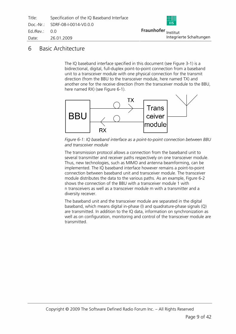
The IQ baseband interface specified in this document (see Figure 3-1) is a bidirectional, digital, full-duplex point-to-point connection from a baseband unit to a transceiver module with one physical connection for the transmit direction (from the BBU to the transceiver module, here named TX) and another one for the receive direction (from the transceiver module to the BBU, here named RX) (see Figure 6-1).
Figure 6-1: IQ baseband interface as a point-to-point connection between BBU and transceiver module
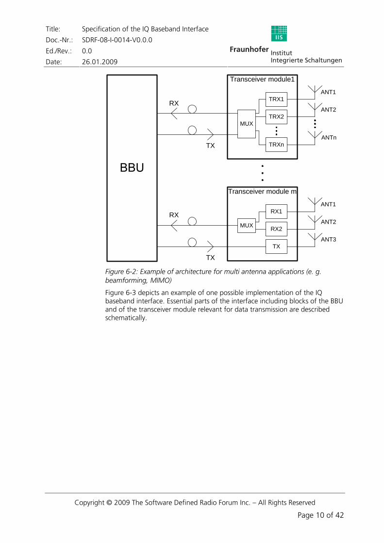
The transmission protocol allows a connection from the baseband unit to several transmitter and receiver paths respectively on one transceiver module. Thus, new technologies, such as MIMO and antenna beamforming, can be implemented. The IQ baseband interface however remains a point-to-point connection between baseband unit and transceiver module. The transceiver module distributes the data to the various paths. As an example, Figure 6-2 shows the connection of the BBU with a transceiver module 1 with n transceivers as well as a transceiver module m with a transmitter and a diversity receiver.
The baseband unit and the transceiver module are separated in the digital baseband, which means digital in-phase (I) and quadrature-phase signals (Q) are transmitted. In addition to the IQ data, information on synchronization as well as on configuration, monitoring and control of the transceiver module are transmitted.
Figure 6-3 depicts an example of one possible implementation of the IQ baseband interface. Essential parts of the interface including blocks of the BBU and of the transceiver module relevant for data transmission are described schematically.
Figure 6-2: Example of architecture for multi antenna applications (e. g. beamforming, MIMO)
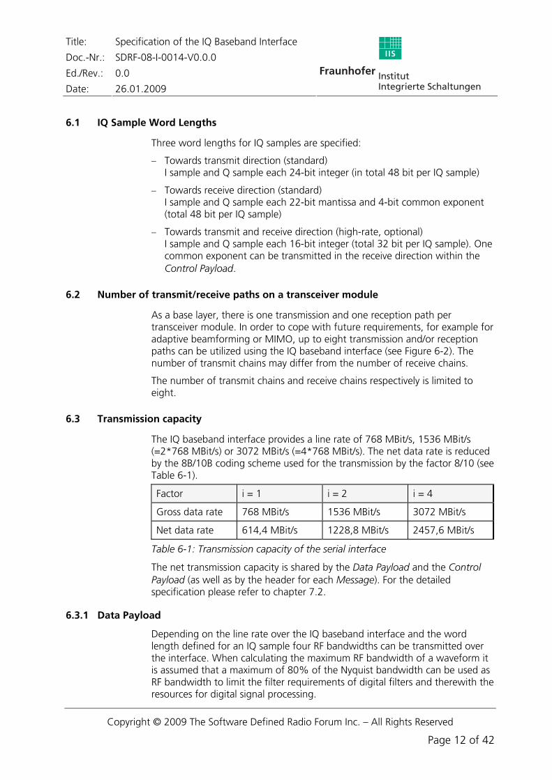
− Towards transmit direction (standard) I sample and Q sample each 24-bit integer (in total 48 bit per IQ sample)
− Towards receive direction (standard) I sample and Q sample each 22-bit mantissa and 4-bit common exponent (total 48 bit per IQ sample)
− Towards transmit and receive direction (high-rate, optional) I sample and Q sample each 16-bit integer (total 32 bit per IQ sample). One common exponent can be transmitted in the receive direction within the Control Payload.
6.2 Number of transmit/receive paths on a transceiver module
As a base layer, there is one transmission and one reception path per transceiver module. In order to cope with future requirements, for example for adaptive beamforming or MIMO, up to eight transmission and/or reception paths can be utilized using the IQ baseband interface (see Figure 6-2). The number of transmit chains may differ from the number of receive chains.
The number of transmit chains and receive chains respectively is limited to eight.
6.3 Transmission capacity
The IQ baseband interface provides a line rate of 768 MBit/s, 1536 MBit/s (=2*768 MBit/s) or 3072 MBit/s (=4*768 MBit/s). The net data rate is reduced by the 8B/10B coding scheme used for the transmission by the factor 8/10 (see Table 6-1).
Factor i = 1 i = 2 i = 4
Gross data rate 768 MBit/s 1536 MBit/s 3072 MBit/s
Net data rate 614,4 MBit/s 1228,8 MBit/s 2457,6 MBit/s
Table 6-1: Transmission capacity of the serial interface
The net transmission capacity is shared by the Data Payload and the Control Payload (as well as by the header for each Message). For the detailed specification please refer to chapter 7.2.
6.3.1 Data Payload
Depending on the line rate over the IQ baseband interface and the word length defined for an IQ sample four RF bandwidths can be transmitted over the interface. When calculating the maximum RF bandwidth of a waveform it is assumed that a maximum of 80% of the Nyquist bandwidth can be used as RF bandwidth to limit the filter requirements of digital filters and therewith the resources for digital signal processing.
Details about the formats of the IQ samples are described in chapter 7.4.3.
6.3.2 Control Payload
The transmission capacity available for the Control Payload is dependent on the line rate of the IQ baseband interface and the transmission capacity defined for the Data Payload.
In order to prevent processing of Control Payloads received including transmission errors, each Control Payload is protected by a cyclic redundancy check (CRC), resulting in a reduced net transmission capacity.
Mode A B C D
Line rate over the interface in MBit/s
768 1536 3072 3072
Gross Control Payload per Message (equals 1 2/3 μs)
26 Byte 58 Byte 26 Byte 26 Byte
Net Control Payload per Message (equals 1 2/3 μs)
24 Byte 56 Byte 24 Byte 24 Byte
Transmission capacity in MByte/s (net)
14,4 33,6 14,4 14,4
Transmission capacity in MBit/s (net)
115,2 268,8 115,2 115,2
Table 6-3: Transmission capacity of Control Payload
Details on the contents of the Control Payload are described in Chapter 7.4.2.
2 48 Bit are composed of 24-bit integer each for an I and a Q sample in TX direction and of 22-bit mantissa each for an I and a Q
sample and 4 Bit common mantissa in RX direction.
3 32 bit are composed of 16-Bit integer each for an I and a Q sample
4 When calculating the maximum bandwidth it is assumed that only 80% of the Nyquist frequency is used, thus limiting the requirements for the digital filters.
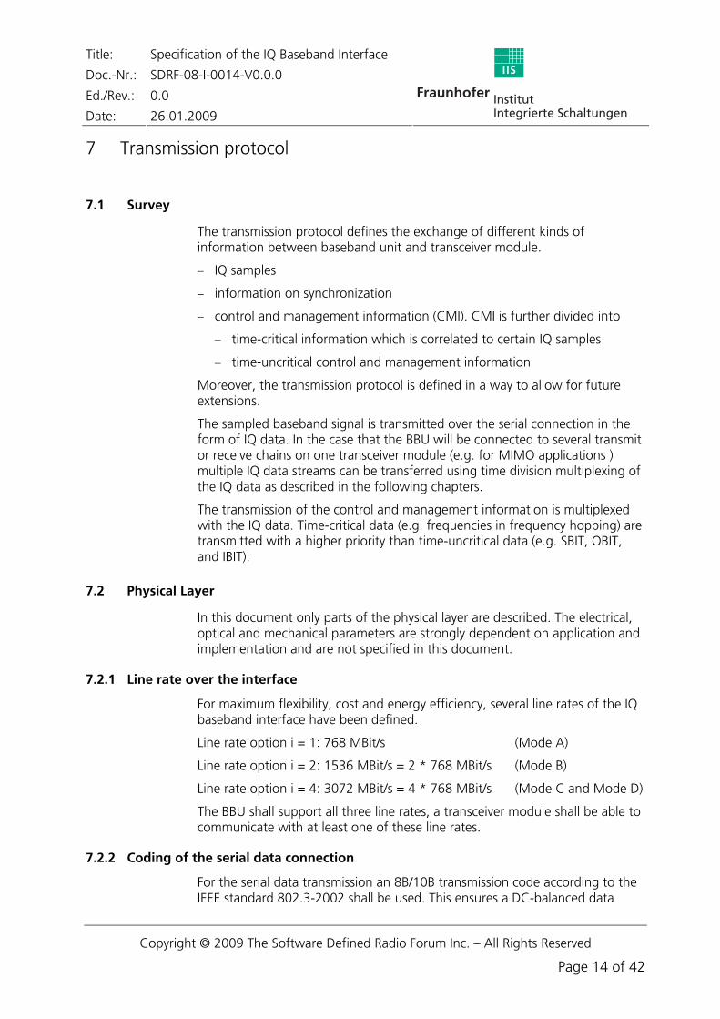
The transmission protocol defines the exchange of different kinds of information between baseband unit and transceiver module.
− IQ samples
− information on synchronization
− control and management information (CMI). CMI is further divided into
− time-critical information which is correlated to certain IQ samples
− time-uncritical control and management information
Moreover, the transmission protocol is defined in a way to allow for future extensions.
The sampled baseband signal is transmitted over the serial connection in the form of IQ data. In the case that the BBU will be connected to several transmit or receive chains on one transceiver module (e.g. for MIMO applications ) multiple IQ data streams can be transferred using time division multiplexing of the IQ data as described in the following chapters.
The transmission of the control and management information is multiplexed with the IQ data. Time-critical data (e.g. frequencies in frequency hopping) are transmitted with a higher priority than time-uncritical data (e.g. SBIT, OBIT, and IBIT).
7.2 Physical Layer
In this document only parts of the physical layer are described. The electrical, optical and mechanical parameters are strongly dependent on application and implementation and are not specified in this document.
7.2.1 Line rate over the interface
For maximum flexibility, cost and energy efficiency, several line rates of the IQ baseband interface have been defined.
Line rate option i = 1: 768 MBit/s (Mode A)
Line rate option i = 2: 1536 MBit/s = 2 * 768 MBit/s (Mode B)
Line rate option i = 4: 3072 MBit/s = 4 * 768 MBit/s (Mode C and Mode D)
The BBU shall support all three line rates, a transceiver module shall be able to communicate with at least one of these line rates.
7.2.2 Coding of the serial data connection
For the serial data transmission an 8B/10B transmission code according to the IEEE standard 802.3-2002 shall be used. This ensures a DC-balanced data
stream, thus allowing a bit recovery and a clock recovery in the receiver of the serial data stream.
Furthermore, the 8B/10B code, additional errors in the connections of the data stream can be detected, thus enabling a feed back on the quality of the connection.
Details about the 8B/10B coding scheme can be found in [5] und [6].
7.2.3 Error detection and correction
The serial data transmission does not provide a forward error correction (FEC) scheme. Control information is protected by an inherent cyclic redundancy check (CRC) in order to detect bit errors and thus protects the device from malfunction by erroneously recognized control information.
7.3 Link Layer
7.3.1 Frame structure
Figure 7-1: Data structure of a Message
The digital data stream over the serial interface is structured into so-called Messages. Figure 7-1 shows the data structure of a Message with 8B/10B coding and the insertion of the Sync Codes K28.7.
Each Message consists of a header, giving information on the content of the Message, and the payload, which is made up of a Control Payload and a Data
Payload. See chapter 7.4.1, 7.4.2 and 7.4.3 for further details on header and payload.
A Message, when being sent, is split into individual bytes. Each byte is encoded with the 8B/10B code before transmission. Bit number zero is sent first.
A Message has a fixed time length of 5/3 μs (≈ 1.67 μs). Thus it contains – depending on the option for the line rate (chapter 7.2.1) – a number of 128, 256 or 512 bytes. The structure of a Message for these serial line rates is shown in Table 7-1.
Field i = 1 i = 2 i = 4
Header 6 Byte 6 Byte 6 Byte
Control Payload 26 Byte 58 Byte 26 Byte
Data Payload 96 Byte 192 Byte 480 Byte
Total length 128 Byte 256 Byte 512 Byte
Table 7-1: Structure of a Message depending on the line rate via a serial interface
RX Messages, as shown in Figure 7-2, are transmitted with the time delay DTRM compared to the TX Messages. DTRM equals half a Message length.
Figure 7-2: Frame offset of TX/RX Messages
7.3.2 Frame synchronization
Before a transmission via the IQ baseband interface is possible, the transceiver module must be synchronized with the BBU and vice versa.
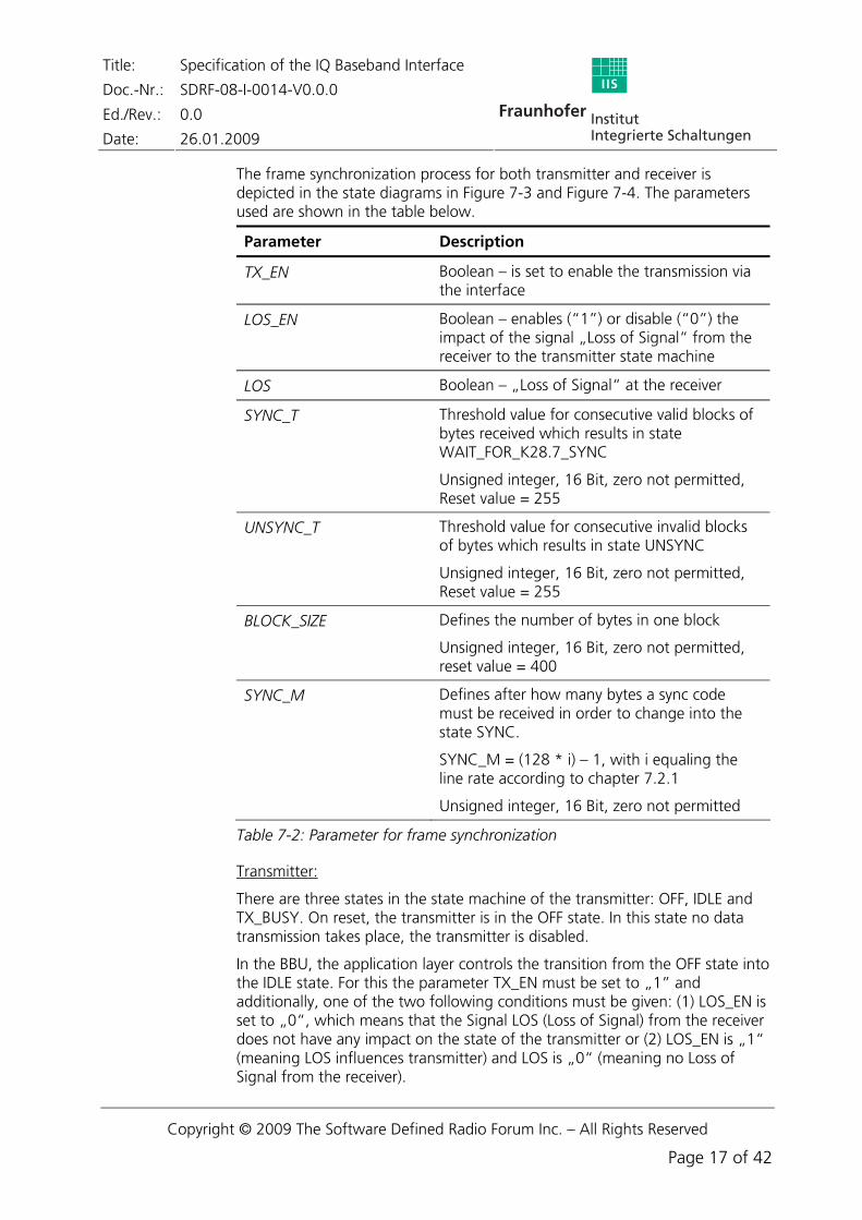
The frame synchronization process for both transmitter and receiver is depicted in the state diagrams in Figure 7-3 and Figure 7-4. The parameters used are shown in the table below.
Parameter Description
TX_EN Boolean – is set to enable the transmission via the interface
LOS_EN Boolean – enables (“1”) or disable (“0”) the impact of the signal „Loss of Signal“ from the receiver to the transmitter state machine
LOS Boolean – „Loss of Signal“ at the receiver
SYNC_T Threshold value for consecutive valid blocks of bytes received which results in state WAIT_FOR_K28.7_SYNC
Unsigned integer, 16 Bit, zero not permitted, Reset value = 255
UNSYNC_T Threshold value for consecutive invalid blocks of bytes which results in state UNSYNC
Unsigned integer, 16 Bit, zero not permitted, Reset value = 255
BLOCK_SIZE Defines the number of bytes in one block
Unsigned integer, 16 Bit, zero not permitted, reset value = 400
SYNC_M Defines after how many bytes a sync code must be received in order to change into the state SYNC.
SYNC_M = (128 * i) – 1, with i equaling the line rate according to chapter 7.2.1
Unsigned integer, 16 Bit, zero not permitted
Table 7-2: Parameter for frame synchronization
Transmitter:
There are three states in the state machine of the transmitter: OFF, IDLE and TX_BUSY. On reset, the transmitter is in the OFF state. In this state no data transmission takes place, the transmitter is disabled.
In the BBU, the application layer controls the transition from the OFF state into the IDLE state. For this the parameter TX_EN must be set to „1” and additionally, one of the two following conditions must be given: (1) LOS_EN is set to „0“, which means that the Signal LOS (Loss of Signal) from the receiver does not have any impact on the state of the transmitter or (2) LOS_EN is „1“ (meaning LOS influences transmitter) and LOS is „0“ (meaning no Loss of Signal from the receiver).
Title: Specification of the IQ Baseband Interface
Doc.-Nr.: SDRF-08-I-0014-V0.0.0
Ed./Rev.: 0.0
Date: 26.01.2009
In the transceiver module, the transition from the OFF state into the IDLE state is controlled by the receiver. The parameter TX_EN is set to „1“ if valid bytes are received from the BBU. These are usually K28.5 IDLES if the BBU and the transceiver module carry out frame synchronization, for example during the initialization after being switched on. If only synchronization of the transceiver module is required, the BBU however is still in TX_BUSY state, valid Messages will be received.
In the IDLE state, K28.5 IDLE bytes are transmitted continuously. This enables the receiver to synchronize the PLL of its reference clock to the bit clock of the interface as well as the interface with the individual samples (bytes).
The finite state machine changes from IDLE to TX_BUSY state if valid K28.5 IDLES are received. In the transceiver module, a transition into the TX_BUSY state is also possible if valid Messages are received (in case only the transceiver module has to resynchronize itself, the BBU, however, is in the TX_BUSY state).
In the TX_BUSY state valid Messages are sent over the interface. The transceiver module sends its Messages to the BBU, delayed by half a Message length.
The transmitter changes into the OFF state if (1) a HW reset is done, (2) if LOS is triggered in the receiver (in case LOS_EN=1) or (3) if the transmitter is disabled by the application layer (TX_EN=0).
OFF
IDLE
TX_ BUSY
HW reset
OFF state:Nothing is transmitted to the interface
IDLE state:K28.5 IDLE bytes are sent to the interface
TX_BUSY state:Formatted data is transmitted
(TX_EN=1 AND LOS_EN=1 AND LOS=0)
(TX_EN=1 AND LOS_EN=0)
Valid K28.5 IDLE bytes received valid
Messages received
(TX_EN=0 (TX_EN=1 AND LOS_EN=1 AND LOS=1) HW reset
(TX_EN=0 (TX_EN=1 AND LOS_EN=1 AND LOS=1) HW reset
The receiver state machine consists of four states: UNSYNC, WAIT_FOR K28.7_SYNC, WAIT_FOR_MESSAGE und SYNC.
Two criteria are applied to synchronize the receiver: (1) the byte error rate of the link is determined and (2) the reception of valid Message lengths is monitored.
After a reset, the receiver is in the UNSYNC state. In this state either no bytes or a great number of invalid bytes are received. The transition into the state WAIT_FOR_K28.7_SYNC takes place if SYNC_T valid, consecutive blocks of bytes were received. A block is received correctly if there was no error in the block during the 8B/10B decoding. The parameters SYNC_T and BLOCK_SIZE have to be defined beforehand.
As soon as a valid K28.7 Sync Code is received, the receiver changes into the state WAIT_FOR_MESSAGE. In this state, the receiver waits for the next K28.7 Sync Code and the number of bytes received is analyzed. If the next Sync Code is received after SYNC_M bytes, the receiver changes into the state SYNC and a regular data transmission begins, otherwise the receiver returns into the state WAIT_FOR_K28.7_SYNC. The value of the parameter SYNC_M depends on the line rate over the interface and can be calculated:
SYNC_M = (128 * i) – 1, with i equaling the line rate according to chapter 7.2.1.
After an HW reset or if UNSYNC_T consecutive invalid blocks are received, the receiver changes from any state directly into the state UNSYNC. A block is invalid if at least one of its bytes is defective during the 8B/10B decoding process.
The link layer only passes on Messages to the application layer in the SYNC state.
7.3.3 Automatic line rate negotiation
The transmission over the IQ baseband interface features different line rates (see chapter 7.2.1). The BBU shall be able to communicate with all of the data rates, a transceiver module shall communicate at least with one of them.
An automatic line rate negotiation is performed if the data rate was not defined beforehand (e.g. when the BBU knows the line rate on which the transceiver module can communicate).
In Table 7-3 the parameters are listed which are used for negotiating the line rate. MaxTxTime must have a sufficient length to enable a successful synchronization. MaxRxTime shall at least be three times MaxTxTime in order to check all three supported line rates of the BBU at each line rate of the transceiver module.
Parameter Description
Synchronization Boolean – indicates whether synchronization and thus line rate negotiation in the BBU is successfully done or not
RxSynchronization Boolean – indicates whether synchronization and thus line rate negotiation in the transceiver module is successfully done or not
TimeOutCounter Counter – in case it reaches a defined value (MaxSynchronizationTime), line rate negotiation is stopped
MaxTxTime Max. transmit time at a certain line rate
MaxRxTime Max. receive time at a certain line rate
MaxSynchronizationTime Time limit for line rate negotiation
Table 7-3: Parameter for line rate negotiation
Algorithm for the Baseband Unit:
1. Set Synchronization=FALSE and start time-out counter TimeOutCounter.
2. Select the lowest line rate that is supported by the BBU (i=1).
3. Attempt synchronization with the transceiver module by carrying out steps 3a-3c. Go to step 4 at the latest after MaxTxTime.
a) Send K28.5 IDLE bytes to the state machine for frame synchronization of the receiver in the transceiver module.
b) When the receiver state machine of the BBU enters the state WAIT_FOR_K28.7_SYNC due to reception of valid K28.5 IDLES from the transceiver module, start transmitting to the transceiver module in valid Message format.
c) When the BBU receiver state machine for frame synchronization of the BBU changes into the state SYNC, set Synchronization=TRUE (synchronization and line rate negotiation have been completed).
4. In case Synchronization=FALSE and TimeOutCounter is less than MaxSynchronizationTime, change to the next higher line rate that is supported or go the lowest line rate if the highest line rate had already been reached. Return to step 3.
5. End of algorithm.
Algorithm for the transceiver module:
1. Set RxSynchronization=FALSE and start a time-out counter TimeOutCounter
2. Choose the lowest line rate supported by the transceiver module
3. Attempt to synchronize with the BBU by carrying out step 3a-3c. Go to step 4 at the latest after MaxRxTime.
a) Start the receiver state machine for the frame synchronization (see chapter 7.3.2).
b) When the receiver state machine enters the state WAIT_FOR_K28.7_SYNC due to reception of valid K28.5 IDLES from the BBU, start transmission of K28.5 IDLE bytes back to the BBU.
c) When the receiver state machine enters the state SYNC, start transmission of valid Messages to the BBU and set RxSynchronization=TRUE.
4. In case RXSynchronization=FALSE and TimeOutCounter is less than MaxSynchronizationTime, change to the next higher line rate that is supported or go to the lowest line rate if the highest line rate supported by the transceiver had already been reached. Return to step 3.
5. End of algorithm.
7.3.4 Commanded change of the line rate
If the BBU wants to start a waveform which demands a higher line rate over the interface as currently set, a change of the line rate must be commanded to the transceiver module. As synchronization has already been established, data in Message format can be exchanged and the available line rates of the transceiver module can be queried.
If the transceiver module is able to communicate with the required higher data rate, the BBU commands via the Control Payload to set a new data rate.
In Table 7-4, parameters are listed which are used for changing the data rate. MaxTxTime must be defined having a sufficient length to enable a successful synchronization.
Synchronization Boolean – indicates whether synchronization and thus line rate negotiation in the BBU is successfully done or not
RxSynchronization Boolean – indicates whether synchronization and thus line rate negotiation in the transceiver module is successfully done or not
NewDataRate Boolean – signals whether the new line rate is set or not
MaxTxTime Time limit for line rate negotiation
Table 7-4: Parameter for commanded line rate negotiation
Algorithm for the base band unit:
1. Set Synchronization=FALSE.
2. Choose the required data rate and set NewDataRate=TRUE.
3. Attempt synchronization with the transceiver module by carrying out steps 3a-3c. Go to step 4 at the latest after MaxTxTime.
a) Send K28.5 IDLE bytes to the state machine for frame synchronization of the receiver in the transceiver module.
b) When the receiver state machine of the BBU enters the state WAIT_FOR_K28.7_SYNC due to reception of valid K28.5 IDLES from the transceiver module, start transmitting to the transceiver module in valid Message format.
c) When the state machine of the BBU enters the state SYNC for frame synchronization, set Synchronization=TRUE (synchronization and line rate negotiation have been completed).
4. If Synchronization=FALSE and NewDataRate=TRUE, change to the line rate that had been set first and had allowed synchronization. Set NewDataRate=FALSE and return to step 3.
5. End of algorithm.
Algorithm for the transceiver module:
1. Set RxSynchronization=FALSE
2. Choose the requested data rate and set NewDataRate=TRUE
3. Attempt to synchronize with the BBU by carrying out step 3a-3c. Go to step 4 at the latest after MaxRxTime.
a) Start the receiver state machine for frame synchronization (see chapter 7.3.2).
Title: Specification of the IQ Baseband Interface
Doc.-Nr.: SDRF-08-I-0014-V0.0.0
Ed./Rev.: 0.0
Date: 26.01.2009
b) When the receiver state machine enters the state WAIT_FOR_K28.7_SYNC due to reception of valid K28.5 IDLES from the BBU, start transmission of K28.5 IDLE bytes back to the BBU.
c) When the receiver state machine enters the state SYNC, start transmission of valid Messages to the BBU and set RxSynchronization=TRUE.
4. In case of RXSynchronization=FALSE und NewDataRate=TRUE, change to the line rate that had been set first and had allowed synchronization. Set NewDataRate=FALSE and return to step 3.
5. End of algorithm.
7.4 Application layer
7.4.1 Message Header
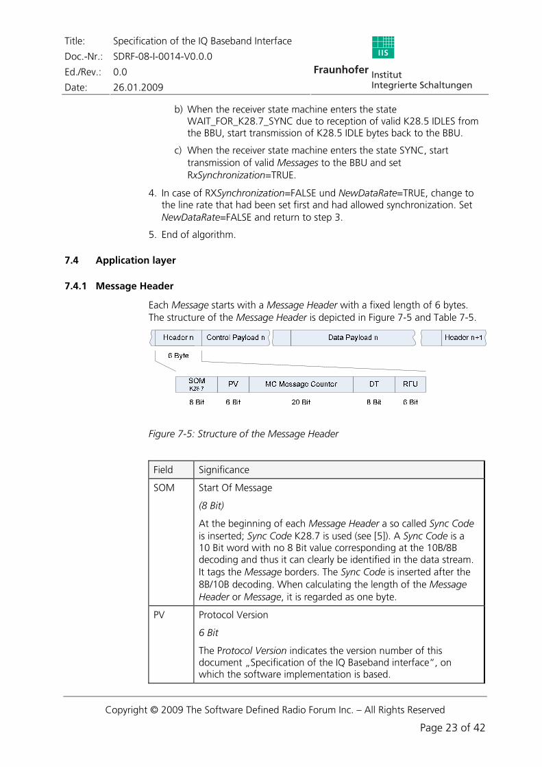
Each Message starts with a Message Header with a fixed length of 6 bytes. The structure of the Message Header is depicted in Figure 7-5 and Table 7-5.
Figure 7-5: Structure of the Message Header
Field Significance
SOM Start Of Message
(8 Bit)
At the beginning of each Message Header a so called Sync Code is inserted; Sync Code K28.7 is used (see [5]). A Sync Code is a 10 Bit word with no 8 Bit value corresponding at the 10B/8B decoding and thus it can clearly be identified in the data stream. It tags the Message borders. The Sync Code is inserted after the 8B/10B decoding. When calculating the length of the Message Header or Message, it is regarded as one byte.
PV Protocol Version
6 Bit
The Protocol Version indicates the version number of this document „Specification of the IQ Baseband interface“, on which the software implementation is based.
The first three bits represent the edition number, the next three bits the revision number. The version of the document that has been released first is referenced in the Header with 000000. Then it will be counted up according to the version number of the document.
MC Message Counter
20 Bit
The MC counts the Messages from 0 to 599 999, i.e. exactly one second and starts again with 0 after reset.
DT Data Type
8 Bit
First, the format of the Data Payload is determined and second, it is signaled whether valid IQ samples are transmitted within the Message or not.
Bit 0 is set if valid IQ samples are transmitted. Data are e.g. invalid if the transmitter or the receiver is disabled, the interface, however, is active.
Bit 1 determines the length of an IQ sample. Bit 1 is set if only 4 bytes per IQ sample are used (mode D).
Bit 2 and 3 are not yet defined (in the transmitter they shall be transmitted with “0” and shall be ignored in the receiver).
Bit 4 to 7 indicate how many transmitters or receivers per transceiver module are addressed. Only one of the four bits can be set. Bit 4 to 7 can also be set if only one transmitter or receiver exists on the transceiver module. This reduces the sample rate per transmitter or receiver (the setting of bit 5 means reducing the sample rate by half, the setting of bit 6 means reducing it to ¼).
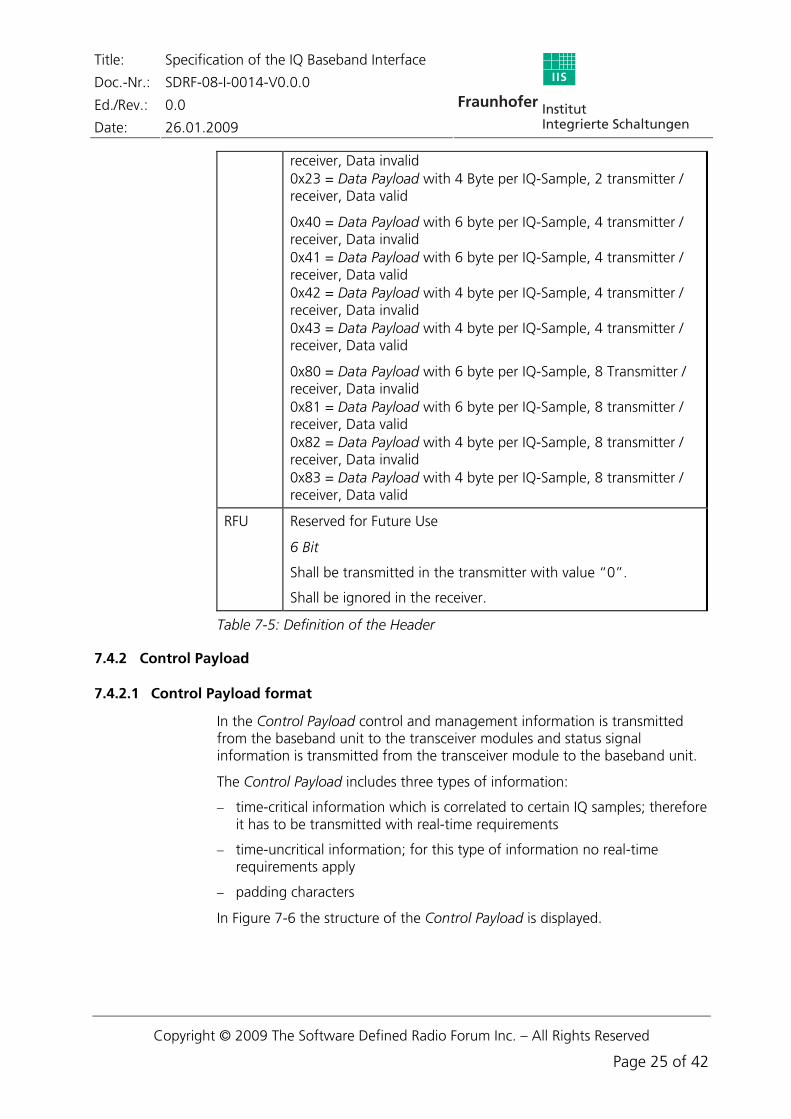
At the moment the following types are defined:
0x00 = Data undefined, use e.g in Init Phase 0x10 = Data Payload with 6 byte per IQ-Sample, 1 transmitter / receiver, Data invalid 0x11 = Data Payload with 6 byte per IQ-Sample, 1 transmitter / receiver, Data valid 0x12 = Data Payload with 4 byte per IQ-Sample, 1 transmitter / receiver, Data invalid 0x13 = Data Payload with 4 byte per IQ-Sample, 1 transmitter / receiver, Data valid
0x20 = Data Payload with 6 byte per IQ-Sample, 2 transmitter / receiver, Data invalid 0x21 = Data Payload with 6 byte per IQ-Sample, 2 transmitter / receiver, Data valid 0x22 = Data Payload with 4 byte per IQ-Sample, 2 transmitter /
receiver, Data invalid 0x23 = Data Payload with 4 Byte per IQ-Sample, 2 transmitter / receiver, Data valid
0x40 = Data Payload with 6 byte per IQ-Sample, 4 transmitter / receiver, Data invalid 0x41 = Data Payload with 6 byte per IQ-Sample, 4 transmitter / receiver, Data valid 0x42 = Data Payload with 4 byte per IQ-Sample, 4 transmitter / receiver, Data invalid 0x43 = Data Payload with 4 byte per IQ-Sample, 4 transmitter / receiver, Data valid
0x80 = Data Payload with 6 byte per IQ-Sample, 8 Transmitter / receiver, Data invalid 0x81 = Data Payload with 6 byte per IQ-Sample, 8 transmitter / receiver, Data valid 0x82 = Data Payload with 4 byte per IQ-Sample, 8 transmitter / receiver, Data invalid 0x83 = Data Payload with 4 byte per IQ-Sample, 8 transmitter / receiver, Data valid
RFU Reserved for Future Use
6 Bit
Shall be transmitted in the transmitter with value “0”.
Shall be ignored in the receiver.
Table 7-5: Definition of the Header
7.4.2 Control Payload
7.4.2.1 Control Payload format
In the Control Payload control and management information is transmitted from the baseband unit to the transceiver modules and status signal information is transmitted from the transceiver module to the baseband unit.
The Control Payload includes three types of information:
− time-critical information which is correlated to certain IQ samples; therefore it has to be transmitted with real-time requirements
− time-uncritical information; for this type of information no real-time requirements apply
− padding characters
In Figure 7-6 the structure of the Control Payload is displayed.
Title: Specification of the IQ Baseband Interface
Doc.-Nr.: SDRF-08-I-0014-V0.0.0
Ed./Rev.: 0.0
Date: 26.01.2009
Figure 7-6: Structure of the Control Payload
Within the Control Payload of a Message several time-critical (TC), several time-uncritical (TU), and padding (PD) Control Packets can be transmitted. At the beginning of each Control Packet a Control Header is transmitted that informs about type and length of the control data. For each line rate a fixed size of the Control Payload is defined. Padding is used to fill up Control Payload to the defined size.
Control Header
The Control Header has a fixed length of one byte and has an identical structure for time-critical, time-uncritical and padding data packets. Size, contents and function of the individual parts of the Control Header are depicted in Table 7-6 and Figure 7-6.
Field Meaning
Type Type of Control Packet (2 Bit, including MSB)
10 = TC – time-critical information
01 = TU – time-uncritical information
11 = PD – padding
Length Length of Control Data (6 Bit, including LSB)
This field indicates the number of bytes of the control data of this packet (within this Message) excluding the Control Header.
Table 7-6: Definition of the Control Header
Time-critical information (TC):
If time-critical information are to be transmitted, these will be transmitted at the beginning of the Control Payload. Time-critical data packets cannot be distributed over multiple Messages.
Time-uncritical information can only be transmitted within the Control Payload of a Message when the payload is not completely filled up by time-critical information packets. Time-uncritical data packets can be distributed to several Messages. This way, larger blocks of data, such as file transfers, can be transmitted.
Padding (PD):
Padding control packets are used to fill up the Control Payload to the size defined for the used line rate. Length of padding control data shall always be zero. Thus only PD Control Headers are used for padding.
7.4.2.2 Error protection of the Control Payload
The Control Payload of each Message is protected by a 16 bit CRC. The CRC is used for the entire Control Payload including the Control Header.
Generator Polynomial X16+X12+X5+1 is used with the most significant bit (MSB) transmitted first. The CRC shift register is initialized by setting all elements to logical „1“. Each Control Payload enters the shift register MSB first, i.e. by the first bit of the first Control Header.
7.4.3 Data Payload
Within the Data Payload of a Message the IQ samples which are sent via the serial IQ baseband interface are transmitted. The length of one Data Payload, as defined in chapter 7.3.1, is 96, 192, and 480 bytes respectively. The word length for one IQ sample is 48 Bit, i.e. 6 byte by default. With a fixed Message length of 1.67 μs, this results in the following three sample rates:
− 9,6 Msamples/second
− 19,2 Msamples/second and
− 48 Msamples/second
If the waveforms shall be transmitted by maximum bandwidth, no higher dynamic range can be obtained by down sampling in the receiver or up sampling in the transmitter as the data have to be transmitted over the interface with the complete sample rate. In this case, 16-bit word length each for I and Q and thus a complete word length of 32 bits per IQ sample are sufficient. That is why a fourth transmission mode with reduced word length for an IQ sample of 32 bits was defined. The maximum sample rate is calculated by 480 byte per Data Payload and 1.67 μs per Message length, resulting in:
Standard IQ sample in TX direction By default, 24 bits in two's complement are transmitted for IQ data (i.e. 6 bytes for each IQ sample) in transmit direction, with the MSB always being transmitted first. Figure 7-7 depicts how the 16 IQ samples for the lowest data rate (i = 1) are embedded into the Data Payload. The same structure is used for the higher data rates (i = 2 and i = 4) with 32 IQ samples and 80 IQ samples respectively being contained in one Data Payload.
96 Byte
IQ-Sample 0 IQ-Sample 1 IQ-Sample 2
6 Byte6 Byte 6 Byte
I High Byte I Low Byte Q High Byte Q Low ByteI Mid Byte Q Mid Byte
IQ-Sample 15
6 Byte
Header n Header n+1
. . .
Data Payload n
26 Byte
Control Payload n
Figure 7-7: Mapping of IQ data for TX within the Data Payload for the case i = 1
Standard IQ sample in the RX direction In receive direction, the IQ samples are transmitted exponentially with 22 bit mantissa (two's complement, MSB first) and 4 bit exponents, with only one common exponent for an IQ sample being transmitted (i.e. 6 byte for each IQ sample). Figure 7-8 shows how the 16 IQ samples for the lowest data rate (i = 1) is embedded into the Data Payload. The same structure is used for the higher data rates (i = 2 and i = 4) with 32 IQ samples and 80 IQ samples respectively being contained in one Data Payload.
Figure 7-8: Mapping of IQ data for RX within the Data Payload for the case i = 1
High-sample-rate IQ sample (in TX and RX direction)
For very broadband waveforms, 16 bit in two's complement for IQ data can optionally be transmitted (i.e. 4 bytes for each IQ sample), with the MSB being always transmitted first. Figure 7-9 shows how the 120 IQ samples are
Figure 7-9: Mapping of IQ data for TX within the Data Payload for a shorter word length resulting in a higher sample rate
To compensate changes in AGC levels, an 8 bit wide exponent is transmitted in the Control Payload with each Message. In case the AGC does not change synchronously to the Messages, an AGC sample reference is transmitted in addition to the exponent. The AGC sample reference describes how many IQ samples have been transmitted between the instant of changing the AGC level and the header. In other words, at the event of the AGC change a counter is started and the counter reading is transmitted in the next Control Payload with an 8 bit word length.
In the example in Figure 7-10, there was a change in the gain level after sample no 23. From sample no. 24 onwards, the counter is incremented by 1 to 96. This value will be transmitted with the new exponent in the Control Payload of the next Message.
If there is no change in AGC levels in the previous Data Payload or if the change of level takes place exactly between two Messages, the AGC sample reference receives the value “0”.
Figure 7-10: Determination of the AGC sample reference for an altered exponent in the direction of RX (high sample rate)
7.4.3.2 Data Payload for several transmitters or receivers on a transceiver module
In order to allow for multiple transmitters and receivers on one transceiver module multiple IQ streams (1, 2, 4 or 8) can be multiplexed into the Data Payload. This, for example, allows applications with multiple antenna systems (e.g. beam forming, MIMO – see also chapter 6).
The number of transmitters does not have to be identical to the number of receivers on the transceiver module. That means the format of the Data Payload can be defined in different ways for TX and RX (see chapter 7.4.1, Data Type DT, also see Figure 6-2).
During initialization, the transceiver module must communicate the number of transmitters and receivers on the module to the BBU (default setting is one transmitter and one receiver on the transceiver module).
Multiplexing is accomplished by successively transmitting the IQ samples from each IQ stream (see Figure 7-11).
Figure 7-11: Mapping of IQ data for n transmitters/receivers within the Data Payload for the case i = 1
7.4.3.3 Reduced sample rate via Data Payload
Transmitting a multiplexed IQ stream can also be done in order to reduce the sampling rate of the IQ stream. Via the Data Type in the Header of the Message the content of unused IQ streams is marked as invalid.
Example:
In mode A (line rate over the interface 768 Mbit/s) one Data Payload contains 96 bytes or 16 samples, the maximum sample rate is set to 9.6 MSamples/s (if bit 4 is set in DT).
If bit 6 is set instead of bit 4 in DT although only one transmitter or receiver is available on the transceiver module, only 4 of the 16 samples (Sample 0, 4, 8 and 12) are sent to the transmitter in the tansceiver module or to the receiver in the baseband unit. The remaining bits are rejected. This way, the sample rate is reduced by factor 4 to 2.4 MSamples/s. Figure 7-12 clarifies this example.
Time synchronization is the ability to enter into an action at defined points in time or to assign a point in time to past events.
Over the IQ baseband interface time synchronization is for example used for
− transmission of TX samples at defined points in time
− assignment of received RX samples to a defined point in time
− switching on and off of receiver or transmitters and switch between transmitting and receiving at defined points in time
− change of transmission/reception frequency at defined points in time
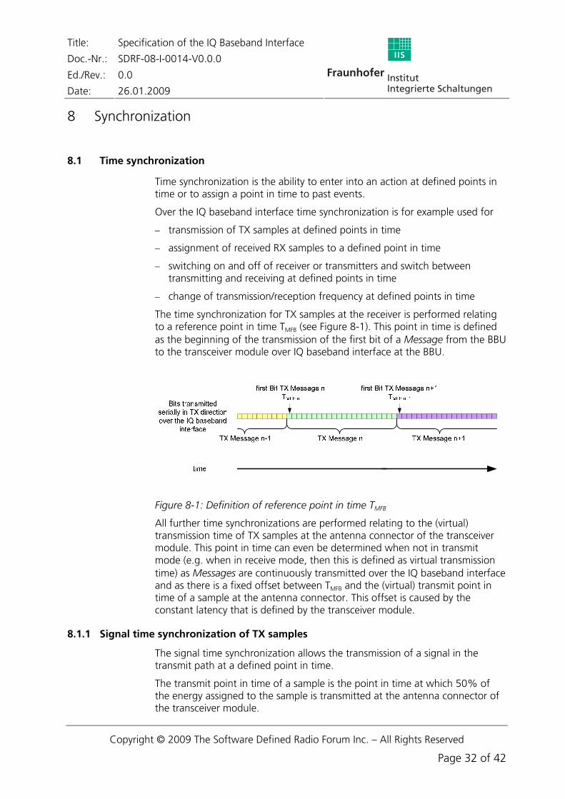
The time synchronization for TX samples at the receiver is performed relating to a reference point in time TMFB (see ). This point in time is defined as the beginning of the transmission of the first bit of a Message from the BBU to the transceiver module over IQ baseband interface at the BBU.
B Figure 8-1
Figure 8-1: Definition of reference point in time TMFBB
All further time synchronizations are performed relating to the (virtual) transmission time of TX samples at the antenna connector of the transceiver module. This point in time can even be determined when not in transmit mode (e.g. when in receive mode, then this is defined as virtual transmission time) as Messages are continuously transmitted over the IQ baseband interface and as there is a fixed offset between TMFB and the (virtual) transmit point in time of a sample at the antenna connector. This offset is caused by the constant latency that is defined by the transceiver module.
8.1.1 Signal time synchronization of TX samples
The signal time synchronization allows the transmission of a signal in the transmit path at a defined point in time.
The transmit point in time of a sample is the point in time at which 50% of the energy assigned to the sample is transmitted at the antenna connector of the transceiver module.
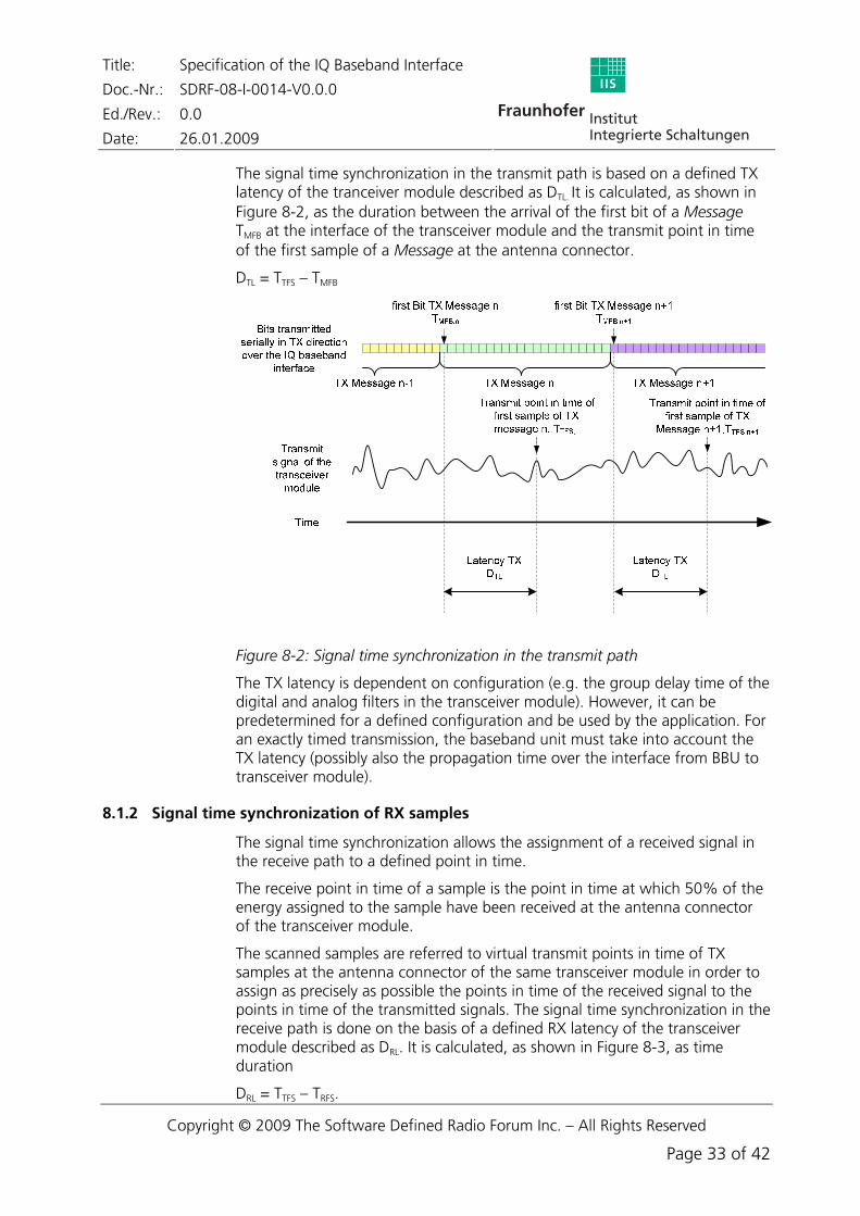
The signal time synchronization in the transmit path is based on a defined TX latency of the tranceiver module described as DTL. It is calculated, as shown in Figure 8-2, as the duration between the arrival of the first bit of a Message TMFB at the interface of the transceiver module and the transmit point in time of the first sample of a Message at the antenna connector.
DTL = TTFS – TMFB
Figure 8-2: Signal time synchronization in the transmit path
The TX latency is dependent on configuration (e.g. the group delay time of the digital and analog filters in the transceiver module). However, it can be predetermined for a defined configuration and be used by the application. For an exactly timed transmission, the baseband unit must take into account the TX latency (possibly also the propagation time over the interface from BBU to transceiver module).
8.1.2 Signal time synchronization of RX samples
The signal time synchronization allows the assignment of a received signal in the receive path to a defined point in time.
The receive point in time of a sample is the point in time at which 50% of the energy assigned to the sample have been received at the antenna connector of the transceiver module.
The scanned samples are referred to virtual transmit points in time of TX samples at the antenna connector of the same transceiver module in order to assign as precisely as possible the points in time of the received signal to the points in time of the transmitted signals. The signal time synchronization in the receive path is done on the basis of a defined RX latency of the transceiver module described as DRL. It is calculated, as shown in Figure 8-3, as time duration
Receive point in time of first sample of RX message n, TRFS,n
Latency RXDRL
timeLatency RX
DRL
Transmit signal of the transceiver
module
Transmit point in time of first sample of
TX message n, TTFS,n
Transmit point in time of first sample of
TX message n+1,TTFS,n+1
Bits transmitted serially in TX direction over the IQ baseband interface
TX Message n TX Message n+1
RX Message n-1 RX Message n RX Message n+1
Receive point in time of first sample of RX message
n+1, TRFS,n+1
Bits transmitted serially in RX direction over the IQ baseband
interface
Receive signal of the transceiver
module
Figure 8-3: signal time synchronization in the receive path
Note: DRL can be negative
The RX latency is dependent on configuration (e.g. the group delay time of the digital and analog filters in the transceiver module). However, it can be predetermined for a defined configuration and be used by the application.
8.1.3 Time synchronization of events
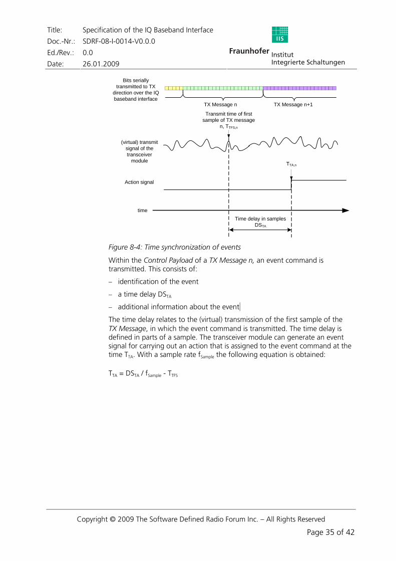
Events such as frequency jumps are referred to virtual transmit points in time of TX samples at the antenna connector of the same transceiver module in order to assign as precisely as possible the points in time of events (e.g. frequency hop, change of gain by AGC) to the points in time of the transmitted or received signals (see Figure 8-4).
Within the Control Payload of a TX Message n, an event command is transmitted. This consists of:
− identification of the event
− a time delay DSTA
− additional information about the event
The time delay relates to the (virtual) transmission of the first sample of the TX Message, in which the event command is transmitted. The time delay is defined in parts of a sample. The transceiver module can generate an event signal for carrying out an action that is assigned to the event command at the time TTA. With a sample rate fSample the following equation is obtained:
Figure 8-5: Realization of the time synchronization of events
Figure 8-5 represents an example implementation of generating an event signal in the transceiver module. The event signal is separated from the data stream in the Messages by means of a Data/Cmd Demux. The transmitted time delay is added to a time delay Time Delta that is determined by the transceiver module. This is set to be the initial value of the down counter which is timed with the sample clock. A signal that is related to the (virtual) transmit point in time of the Message’s first sample starts the down counter. When the counter arrives at zero the action signal is triggered.
8.2 Frequency Synchronization
The IQ baseband interface shall enable the transceiver module to keep high frequency accuracy without having its own highly accurate frequency standard (e.g. oven controlled crystal oscillator).
The transceiver module shall for example synchronize its reference clock for generating the required frequency (e.g. for sampling, local oscillators, as well as the bit clock for the interface in receive direction) via a PLL to the bit clock of the IQ baseband interface.
[5] A. X. Widmer, P. A. Franszek, A DC-Balanced, Partitioned-Block, 8B/10B Transmissioen Code, IBM Journal of Research and Development, Vol. 27, No. 5, pp. 440-451, Sept. 1983
[6] IEEE Standard for information technology – Part 3: Carrier sense multiple access with collision detection (CSMA/CD) access method and physical layer specifications, IEEE Std. 802.3-2005
[7] IEEE: Part 3: Carrier sense multiple access with collision detection (CSMA/CD) access method and physical layer specifications, Amendment: Media Access Control (MAC) Parameters, Physical Layers, and Management Parameters for 10 GB/s Operation, IEEE Std. 802.3ae-2002, March 2002
Figure 3-1: Modular SDR architecture ...........................................................................................5 Figure 6-1: IQ baseband interface as a point-to-point connection between BBU and transceiver
module ......................................................................................................................9 Figure 6-2: Example of architecture for multi antenna applications (e. g. beamforming, MIMO) ..10 Figure 6-3: Example for the realization of the IQ Baseband Interface ...........................................11 Figure 7-1: Data structure of a Message......................................................................................15 Figure 7-2: Frame offset of TX/RX Messages ...............................................................................16 Figure 7-3: State diagram of the transmitter ...............................................................................18 Figure 7-4: State diagram of the receiver ....................................................................................19 Figure 7-5: Structure of the Message Header ..............................................................................23 Figure 7-6: Structure of the Control Payload ...............................................................................26 Figure 7-7: Mapping of IQ data for TX within the Data Payload for the case i = 1........................28 Figure 7-8: Mapping of IQ data for RX within the Data Payload for the case i = 1........................28 Figure 7-9: Mapping of IQ data for TX within the Data Payload for a shorter word length resulting
in a higher sample rate.............................................................................................29 Figure 7-10: Determination of the AGC sample reference for an altered exponent in the direction
of RX (high sample rate) ...........................................................................................29 Figure 7-11: Mapping of IQ data for n transmitters/receivers within the Data Payload for the case
i = 1.........................................................................................................................30 Figure 7-12: Mapping of IQ data within the Data Payload when reducing the data rate by factor 4
for the case i = 1......................................................................................................31 Figure 8-1: Definition of reference point in time TMFB...................................................................32 Figure 8-2: Signal time synchronization in the transmit path .......................................................33 Figure 8-3: signal time synchronization in the receive path..........................................................34 Figure 8-4: Time synchronization of events .................................................................................35 Figure 8-5: Realization of the time synchronization of events ......................................................36
Table 6-1: Transmission capacity of the serial interface................................................................12 Table 6-2: Transmission capacity of Data Payload........................................................................13 Table 6-3: Transmission capacity of Control Payload ...................................................................13 Table 7-1: Structure of a Message depending on the line rate via a serial interface......................16 Table 7-2: Parameter for frame synchronization ..........................................................................17 Table 7-3: Parameter for line rate negotiation .............................................................................20 Table 7-4: Parameter for commanded line rate negotiation.........................................................22 Table 7-5: Definition of the Header.............................................................................................25 Table 7-6: Definition of the Control Header ................................................................................26 Table 7-7: Sample rates over the interface ..................................................................................31