+ All Categories
Home > Documents > Software Engineering COMP 3400 - System Design The goal of the detailed design phase is to develop...

Software Engineering COMP 3400 - System Design The goal of the detailed design phase is to develop...

Date post: 29-Dec-2015
Category:
Upload: august-stafford
View: 218 times
Download: 0 times
Share this document with a friend
Popular Tags:
35
Software Engineering Software Engineering COMP 3400 - System COMP 3400 - System Design Design The goal of the detailed design phase is to develop the internal logic of each of the modules identified during the system design phase. The structured design methodology used during system design did not precisely specify the modules but rather described the modules in a natural language. Main Get Validated Input b,c,e. Output f,g,h Schedule b,c,e f,g,h Print Timetable Print Conflict Print Explanation h g f
Transcript

Software Engineering Software Engineering COMP 3400 - System COMP 3400 - System

DesignDesign

The goal of the detailed design phase is to develop the internal logic of each of the modules identified during the system design phase.

The structured design methodology used during system design did not precisely specify the modules but rather described the modules in a natural language.

MainMain

Get Validated Input

Get Validated Input

b,c,e.

OutputOutput

f,g,h

ScheduleSchedule

b,c

,e

f,g,

h

PrintTimetable

PrintTimetable

PrintConflict

PrintConflict

PrintExplanation

PrintExplanation

hg

f

Software Engineering - Detailed Software Engineering - Detailed DesignDesign

Formal methods for module specification are intended to ensure that the specifications are precise and are not subject to interpretation by the coder.

Module specifications should be complete, unambiguous, implementation independent and easy to understand.

One technique used is to provide a very high level prototyping language for specifying and testing module specifications

Specifying ModulesSpecifying Modules

Software Engineering - Detailed Software Engineering - Detailed DesignDesign

A functional module can be described in terms of its input and output transform.

Specifying Functional ModulesSpecifying Functional Modules

SORT (L: list of integers)

Sort a list L of integers in ascending order

input: non null L

output:

for all i, 1 i < size(L’)

L’[i] L’[i+1] andL’ = permutation(L)

Software Engineering - Detailed Software Engineering - Detailed DesignDesign

Another formal method for specifying modules is referred to as data abstraction.

This technique requires the use of a formal specification language, which is implementation independent but which shares many of the characteristics of a programming language. See figure 5.2 for specifying a queue.

Formal methods for module specifications are cumbersome, not very expressive, and are hard to write and understand.

Specifying Data AbstractionsSpecifying Data Abstractions

Software Engineering - Detailed Software Engineering - Detailed DesignDesign

Process Design Language (PDL) is a practical way to precisely communicate the meaning of a system or module.

PDL can be thought of as a structured natural language, with some of the precision of a structured programming language and some of the ease of a natural language.

Some amount of automated processing can be done with the PDL design document.

Process Design Language (PDL)Process Design Language (PDL)

Software Engineering - Detailed Software Engineering - Detailed DesignDesign

PDL ExamplePDL Exampleminmax(infile) // Find the max and min

of a string of numbers //ARRAY a

DO UNTIL end of inputREAD an item into a

ENDDOmax, min := first item of aDO FOR each item in a

IF max < item THEN set max to itemIF min > item THEN set min to item

ENDDOEND

Software Engineering - Detailed Software Engineering - Detailed DesignDesign

Notice that in this example, we have the entire logic for the procedure without the implementation details of a particular imperative language.

To code this procedure the programmer needs to relate each of the statements into a construct in the implementation language.

There is little room for coding “creativity” A series of PDL designs can be generated in a

successive refinement approach.

Process Design Language (PDL)Process Design Language (PDL)

Software Engineering - Detailed Software Engineering - Detailed DesignDesign

The constructs of PDL are similar to that of a structured imperative language like Pascal or C:

IF condition THENCASE OF transaction typeCASE OF operator typeDO iteration criteria statement listENDDO

PDL ConstructsPDL Constructs

Software Engineering - Detailed Software Engineering - Detailed DesignDesign

An algorithm is a series of steps that need to be performed to to solve a given problem.

The design of a specific algorithm begins with a statement of the module problem from the System Design Specification.

The use of stepwise refinement techniques and PDL descriptions can be used to gradually convert the module description into a precisely defined algorithm.

PDL permits a series of refinements with varying degrees of precision not available in a specific programming language.

Logic/Algorithm DesignLogic/Algorithm Design

Software Engineering - Detailed Software Engineering - Detailed DesignDesign

• The PDL description of this Data Flow Graph:

Algorithm Design Example - Algorithm Design Example - Counting Different Words Counting Different Words

Get Word List

Get Word List

Print the

Count

Print the

Count

Sort The List

Sort The List

Count the Number

of Different

Words

Count the Number

of Different

Words

Input

WordList:wl

SortedWordList

WordCount

Software Engineering - Detailed Software Engineering - Detailed DesignDesign

• 1st PDL refinement of this Data Flow Graph:

Algorithm Design Example - Algorithm Design Example - Counting Different Words Counting Different Words

Get Word List

Get Word List

Print the

Count

Print the

Count

Sort The List

Sort The List

Count the Number

of Different

Words

Count the Number

of Different

Words

Input

WordList:wl

SortedWordList

WordCount

count (in: file) returns integervar

wl: word_list;begin

sort (wl);count := different_words (wl);print (count);

end;

Software Engineering - Detailed Software Engineering - Detailed DesignDesign

• Three operations require refinement:• read file into word list (wl),• sort word list,• count different words in word list.

• Select one of the three for further refinement.• Refine the reading operation:

Algorithm Design Example - Algorithm Design Example - Counting Different Words Counting Different Words

Software Engineering - Detailed Software Engineering - Detailed DesignDesign

Algorithm Design Example - Algorithm Design Example - Counting Different Words Counting Different Words

read_from_file (in: file, out: wl)begin

initialize wl to empty;repeat

get_a_word from fileadd word to wl

until end_of_fileend;

• Three operations require refinement:• read file into word list (wl),• sort word list,• count different words in word list.

• Select one of the three for further refinement.• Refine the reading operation:

Software Engineering - Detailed Software Engineering - Detailed DesignDesign

Algorithm Design Example - Algorithm Design Example - Counting Different Words Counting Different Words

• Refine the counting operation:

Software Engineering - Detailed Software Engineering - Detailed DesignDesign

Algorithm Design Example - Algorithm Design Example - Counting Different Words Counting Different Words

different_words (in: wl) returns integervar

last, cur: word;cnt: integer;

beginlast: = first word in wl;cnt : = 1;while not end of list

cur : = next word from wl;if (cur ! = last) then begincnt := cnt + 1;last := cur;

end;end;return (cnt);

end.

• Refine the counting operation:

Software Engineering - Detailed Software Engineering - Detailed DesignDesign

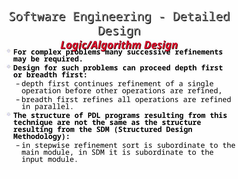
For complex problems many successive refinements may be required.

Design for such problems can proceed depth first or breadth first:– depth first continues refinement of a single operation

before other operations are refined,– breadth first refines all operations are refined in parallel.

The structure of PDL programs resulting from this technique are not the same as the structure resulting from the SDM (Structured Design Methodology):– in stepwise refinement sort is subordinate to the main

module, in SDM it is subordinate to the input module.

Logic/Algorithm DesignLogic/Algorithm Design

Software Engineering - Detailed Software Engineering - Detailed DesignDesign

• The goal of verification in the detailed design phase is to ensure that the detailed design is consistent with system design.

• Three validation methods are:• design walkthroughs• critical design reviews• consistency checkers

VerificationVerification

Software Engineering - Detailed Software Engineering - Detailed DesignDesign

• A meeting is held by the designer or design group leader or designated spokesperson.

• The detailed design is described in step-by-step fashion.• The feedback is usually informal in nature.• The Design Review is more effective and more

expensive.

Design WalkthroughsDesign Walkthroughs

Software Engineering - Detailed Software Engineering - Detailed DesignDesign

A review group, consisting of the detailed design author or team, the system design team, the programming team, the quality assurance organization and perhaps the client is convened.

The review is conducted in a manner similar to the requirements or system design review, i.e., each member is prepared and incented to review the detailed design beforehand and reveal detailed design errors.

The meeting is not intended to fix problems, but rather, to identify them.

A list of action items should be maintained for further reporting or a subsequent meetings.

Critical Design ReviewCritical Design Review

Software Engineering - Detailed Software Engineering - Detailed DesignDesign

Does each of the modules in the system design appear in the detailed design?

Can the performance requirements be met? Are the assumption explicit and acceptable? Are all relevant aspects of system design in the detailed

design? Is the design structured and compatible with local

practices? Are the sizes of data structures explicit? Is each statement codeable? Will the loops terminate? Is the module too complex? Are the modules highly cohesive?

Critical Design Review ChecklistCritical Design Review Checklist

Software Engineering - Detailed Software Engineering - Detailed DesignDesign

A consistency checker is a special purpose PDL compiler which, rather than producing executable target code, ensures that the modules invoked or used by a given module is consistent with the design

A consistency checker can ensure that any modules invoked or used by a given module actually exit in the design and that the caller interface is consistent with the interface definition of the called module.

Consistency checkers can generate complexity metrics. The more formal the design language the better its

checking and the closer it becomes to a formal programming language.

Consistency CheckersConsistency Checkers

Software Engineering - Detailed Software Engineering - Detailed DesignDesign

After the detailed design many important details are known about the software system. Only the implementation details associated with a programming language remain.

Hence, many system metrics can be formulated. Detailed design metrics include:

– Complexity metrics– Data bindings– Cohesion metrics

MetricsMetrics

Software Engineering - Detailed Software Engineering - Detailed DesignDesign

Programs with with many conditional statements tent to be more complex than those with few conditional statements.

A simple measure of complexity is the number of constructs that represent program branches like if then else, while do, and repeat until.

A more refined measure of complexity is the cyclomatic complexity measure, which is based on a control flow graph of a programs logic.

A control flow graph is drawn by breaking a program into blocks delimited by control statements.

These blocks become graphical nodes with arcs connecting branchings between blocks.

The complexity can be calculated by counting the nodes, edges and connections in the control flow graph.

Cyclomatic ComplexityCyclomatic Complexity

Software Engineering - Detailed Software Engineering - Detailed DesignDesign

A module with its corresponding flow graph is shown below:

Cyclomatic ComplexityCyclomatic Complexity

Software Engineering - Detailed Software Engineering - Detailed DesignDesign

A module with its corresponding flow graph is shown below:

Cyclomatic ComplexityCyclomatic Complexity

0 begin1 i = 12 while (i n) do beginj = 1while(j ido5 if A[j] < A[i] then6 swap (A[j], A[i]);7 end if8 end while9 end while10 end

0,1,2

10

3,4

9

5

67,8 The cyclomatic number is the

number of independent circuits in the chart

Software Engineering - Detailed Software Engineering - Detailed DesignDesign

A module with its corresponding flow graph is shown below:

Cyclomatic ComplexityCyclomatic Complexity

0 begin1 i = 12 while (i n) do beginj = 1while(j ido5 if A[j] < A[i] then6 swap (A[j], A[i]);7 end if8 end while9 end while10 end

0,1,2

10

3,4

9

5

67,8 The cyclomatic number is the

number of independent circuits in the chart = 4

Software Engineering - Detailed Software Engineering - Detailed DesignDesign

Data bindings attempt to measure the coupling and cohesion among modules.

A potential data binding counts the number of variables between two modules which are within the same scope. This metric represents the potential for coupling of variables by sharing between modules.

A used data binding is a potential data binding where two modules use the same variable.

An actual data binding occurs when a module assigns a value to a variable and another module uses that value.

All of these binding attempt to represent the strength of interconnections between particular modules.

Data BindingsData Bindings

Software Engineering - Detailed Software Engineering - Detailed DesignDesign

After detailed design, the complexity of modules can be obtained.

If a module is very complex it will be difficult to understand, maintain and modify.

If a module is too complex it can be broken down into two or more less complex modules.

Module ComplexityModule Complexity

Software Engineering - Detailed Software Engineering - Detailed DesignDesign

After a design walkthrough the number of errors per module can be determined.

Assuming a high quality review, a low number of errors implies that the module was well designed.

If the number of errors in module is high it may indicate that there will be problems during the coding phase and careful scrutiny may be required

Errors per ModuleErrors per Module

Software Engineering - Detailed Software Engineering - Detailed DesignDesign

The goal of detailed design is to develop the internal logic of each of the modules identified during the system design.

Methods are available for specifying the logic of a module.

Formal methods exist for specifying modules. One is the axiomatic specification technique,

another is data abstraction.

SummarySummary

Software Engineering - Detailed Software Engineering - Detailed DesignDesign

Unfortunately, the formal methods developed to date tend to be a pain and are rarely used in practice.

A more practical approach is to use a pseudo-language specifically designed for specifying modules during the detailed design phase of a project.

This pseudo-language should be practical enough to be usable yet precise enough to be convertible into code without requiring uncontrolled decisions on the part of the code writers.

SummarySummary

Software Engineering - Detailed Software Engineering - Detailed DesignDesign

We discussed a language called Process Design Language which is used to describe the detailed design of systems and which is used in practice.

PDL can be used to express the detailed design of modules.

PDL has a formal outer syntax and a flexible inner syntax and vocabulary, giving it a balance between formalism and ease of expression.

SummarySummary

Software Engineering - Detailed Software Engineering - Detailed DesignDesign

Several metrics were introduced to evaluate the effectiveness and output of this phase.

We have introduced metrics for evaluating the complexity of modules, the coupling among modules and the quality of modules.

We have discussed verification techniques such as our old friend the design review.

Several automated techniques exist which are based on PDL though the deign review is still the most used.

SummarySummary

Software Engineering - Detailed Software Engineering - Detailed DesignDesign

Design Decisions PDL of main module procedure

– Proc main() PDL of input module procedures

– Proc get_validated_input(file1,file2)– Proc validate_file(file1)– Proc validate_classrooms– Proc validate_dept_courses– Proc validate_lecture_times– Proc validate_file2

Case StudyCase Study

Software Engineering - Detailed Software Engineering - Detailed DesignDesign

PDL of input module procedures– Proc get_ course_index(course_no, course_index)– Proc get_pref_valid(buffer, valid_pref_list)– Proc

form_course_rec(course_index,enrol,valid_pref_list)– Proc separate_course

Case StudyCase Study


Recommended