246
Software Modeling & Analysis KUPE (Konkuk Unified Process for Education) With Case Study -OOPT (Object Oriented Process with Trace) Lecturer: JUNBEOM YOO [email protected]

Software Modeling & Analysis
KUPE (Konkuk Unified Process for Education) With Case Study
-OOPT (Object Oriented Process with Trace)
Lecturer: JUNBEOM [email protected]

What is KUPE?
• KUPE (Konkuk Unified Process for Education)
– A software process based on RUP
– Revision of OSP (by Tailored to SE classes in universities) and OOPT
• Characteristics of KUPE
– 3 Stages
1. Iterative : Multiple development cycles
2. Incremental : System grows incrementally as each cycle is completed
3. Architecture : Stage > Cycle > Phase > Activity
2
Plan andElaboration
Build Deployment1000 2000 3000

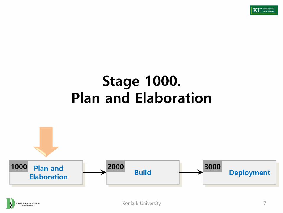
1. 3 Stages
• Stage 1000 : Plan and Elaboration
– Planning, defining requirements, building prototyping, etc
– Corresponding to Inception/Elaboration phases in the RUP
• Stage 2000 : Build
– Construction of the system
– Corresponding to Construct phase in the RUP
• Stage 3000 : Deployment
– Implementation of the system into use
– Corresponding to Transition phase in the RUP
3
Plan andElaboration
Build Deployment1000 2000 3000
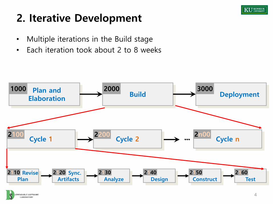
2. Iterative Development
• Multiple iterations in the Build stage
• Each iteration took about 2 to 8 weeks
4
Cycle 1 Cycle 2 Cycle n...
Plan andElaboration
Build Deployment1000 2000 3000
2100 2200 2n00
Revise Plan
2110 Sync.Artifacts
2120
Analyze
2130
Design
2140
Construct
2150
Test
2160

3. Incremental Development
5
Cycle 1 Cycle 2 Cycle n...
Plan andElaboration
Build Deployment1000 2000 3000
2100 2200 2n00
Use-Case ASimplified Version. . .
Use-Case AFull Version. . .
Use-Case DFull Version. . .
Use-Case CFull Version. . .
Use-Case BFull Version. . .
Use-Case CSimplified Version. . .

4. Architecture of KUPE
6
DefineReal Use Cases
2141 DefineReports & UI
2142 RefineSystem Archi.
2143 DefineInteraction D.
2144 DefineDesign Class D
2145 DefineDB Schema
2146
Activity
Stage
Cycle 1 Cycle 2 Cycle n...
Plan andElaboration
Build Deployment1000 2000 3000
2100 2200 2n00
Revise Plan
2110 Sync.Artifacts
2120
Analyze
2130
Design
2140
Construct
2150
Test
2160
Stage 1000.Plan and Elaboration
Konkuk University 7
Plan andElaboration
Build Deployment1000 2000 3000

Stage 1000. Plan and Elaboration
• Stage 1000 Activities
8
Define Business Concept Model
1008
Create PreliminaryInvestigation Report
1002
ImplementPrototype
1005
Define SystemTest Case
1009
DefineRequirements
1003
Define DraftSystem Architecture
1006
Define Business Use Case
1007
DefineDraft Plan
1001
RecordTerms in Glossary
1004 a a,c,db,d
a. ongoingb. optionalc. may deferd. varied order
Plan andElaboration
1000
Refine Plan1010

Activity 1001. Define Draft Plan
• Description
– Write a draft plan for schedule, resources, budget, objective, etc
– Input : related documents of previous similar projects
– Output : a draft project plan
• Steps
1. Write motivation and objective of project
2. Write scope of project
3. Identify and write functional requirements
4. Identify and write non-functional requirements
5. Estimate resources (human efforts(M/M), human resources, duration, budget)
9
DefineDraft Plan
1001 Create PreliminaryInvestigation Report
1002

Activity 1002. Create Preliminary Investigation Report
• Description
– Write an investigation report on alternatives, business needs, risk, etc
– Input : draft project plan
– Output : an investigation report
• Steps
1. Write alternative solutions
2. Write project’s justification (business needs)
3. Identify and manage risks, and write risk reduction plans
4. Analyze business market
5. Write managerial issues
10
DefineDraft Plan
1001 Create PreliminaryInvestigation Report
1002 DefineRequirements
1003

Activity 1003. Define Requirements
• Description
– Write a requirement specification for a product
– Input : draft project plan, investigation report
– Output : a requirement specification
• What is a requirement? (IEEE Std 610.12-1990)
– A condition or capability needed by a user to solve a problem or achieve an objective.
– A condition or capability that must be met or possessed by a system or system component to satisfy a contract, standard, specification, or other formally imposed documents.
– A documented representation of a condition or capabilities as in (1) or (2)
11
Create PreliminaryInvestigation Report
1002 DefineRequirements
1003 RecordTerms in Glossary
1004 a
Activity 1003. Define Requirements
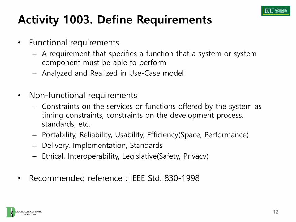
• Functional requirements
– A requirement that specifies a function that a system or system component must be able to perform
– Analyzed and Realized in Use-Case model
• Non-functional requirements
– Constraints on the services or functions offered by the system as timing constraints, constraints on the development process, standards, etc.
– Portability, Reliability, Usability, Efficiency(Space, Performance)
– Delivery, Implementation, Standards
– Ethical, Interoperability, Legislative(Safety, Privacy)
• Recommended reference : IEEE Std. 830-1998
12

Activity 1003. Define Requirements
• Steps
1. Gather all kinds of useful documents
2. Write an overview statement (objective and name of the system, etc.)
3. Determine customers who use the product
4. Write goals of the project
5. Identify system functions
• Functional requirements
• Add function references(such as R1.1, …) into the identified functions
• Categorize identified functions into Event, Hidden, and Frill
6. Identify system attributes
• Non-functional requirements
7. Identify other requirements (Optional)
• Assumptions, Risks, Glossary, etc.
13
Categorization
Eventshould perform / visible to users
Hiddenshould performs / invisible to users
Frill optional
Activity 1004. Record Terms in Glossary
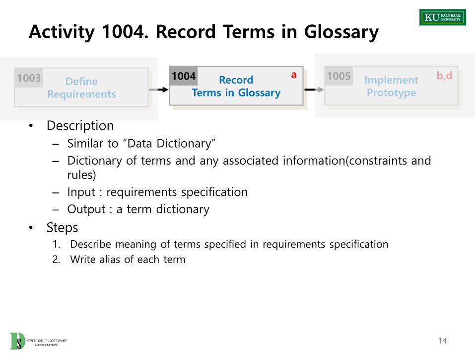
• Description
– Similar to “Data Dictionary”
– Dictionary of terms and any associated information(constraints and rules)
– Input : requirements specification
– Output : a term dictionary
• Steps1. Describe meaning of terms specified in requirements specification
2. Write alias of each term
14
DefineRequirements
1003 RecordTerms in Glossary
1004 ImplementPrototype
1005a b,d

Activity 1005. Implement Prototype
• Description
– Develop a prototype system to permit use feedback, determine feasibility, or investigate timing or other issues
– Input : requirements specification
– Output : a prototype
• Steps1. Develop a prototype
15
RecordTerms in Glossary
1004 ImplementPrototype
1005 Define DraftSystem Architecture
1006b,da a,c,d

Activity 1006. Define Business Use Case
• Description
– To obtain a deeper understanding of the processes and requirements identified so far
– Identify business tasks as business use cases, and illustrate their relationships in use case diagrams
– Input : requirements specification
– Output : a business use case model (High-level use case)
• Business Use Case Diagram
• Business Use Case Description
16
ImplementPrototype
1005 Define Business Use Case
1006 Define Business Concept Model
1007b,d
Cashier
Buy Items
Log In
Refund Items
POST
Customer

Activity 1006. Define Business Use Case
• Steps
1. Determine system boundary in order to identify what is external versus internal, and what the responsibilities of the system are
• Typical system boundary includes:
– Hardware/Software boundary of a device / computer system
– Department of an organization
– Entire organization
17Konkuk University
Cashier Customer
POST
System boundary
Activity 1006. Define Business Use Case
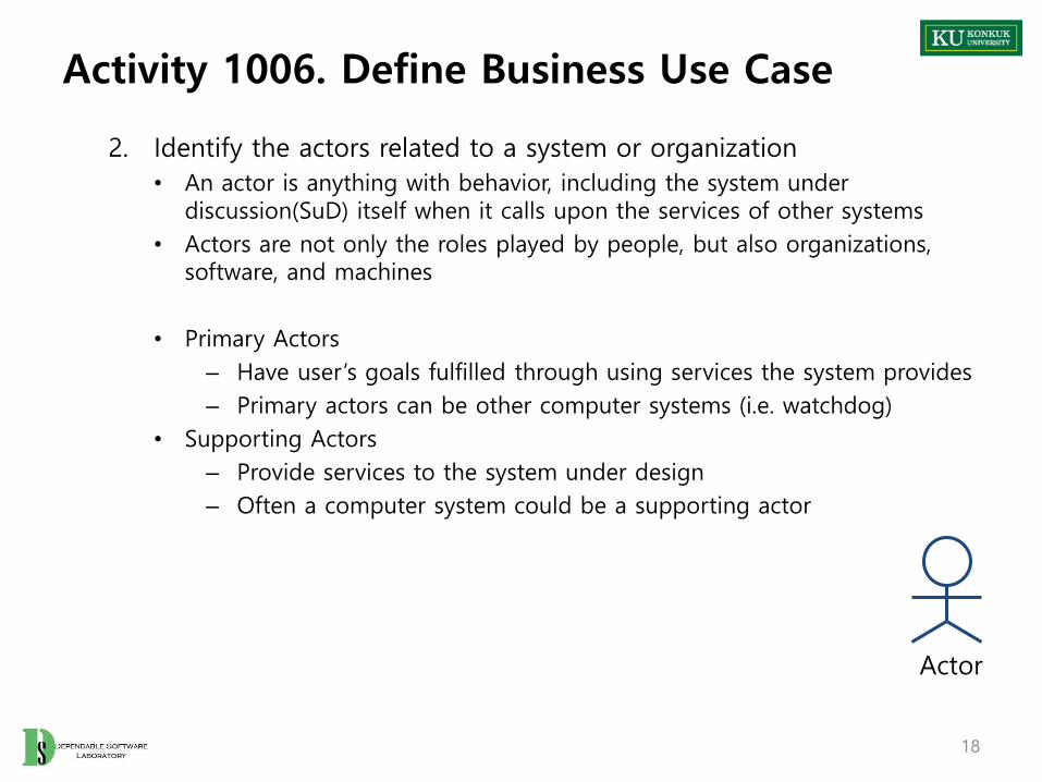
2. Identify the actors related to a system or organization
• An actor is anything with behavior, including the system under discussion(SuD) itself when it calls upon the services of other systems
• Actors are not only the roles played by people, but also organizations, software, and machines
• Primary Actors
– Have user’s goals fulfilled through using services the system provides
– Primary actors can be other computer systems (i.e. watchdog)
• Supporting Actors
– Provide services to the system under design
– Often a computer system could be a supporting actor
18
Actor

Activity 1006. Define Business Use Case
3. Identify user goals for each actor
4. Record the primary actors and their goals in an actor-goal list
19
Actor Goal
Cashier
Process salesProcess rentalsHandle returnsCash inCash out…
System Admin.
Add usersModify usersDelete usersManage securities…

Activity 1006. Define Business Use Case
5. Define use cases that satisfy user goals
• Identify use cases by actor-based
– For each actor, identify the processes they initiate or participate in
• Identify use cases by event-based
– Identify the external events that a system must respond to
– Related the events to actors and use cases
• Name them according to their goals
6. Allocate system functions identified during the requirements specification into related use cases
7. Categorize identified use cases into primary, secondary, and optional use cases
• Primary use cases : major common processes
• Secondary use cases : minor or rare processes
• Optional use cases : processes that may not be tackled
20

Activity 1006. Define Business Use Case
8. Identify relationships between use cases
• Write major steps or branching activities of one use case as several separate use cases using “include” relationship, when they are too complex, long, and duplicated to understand
• Use “extends” relationship when an exceptional activity is occurred in use case
21
Buy Items
Pay by Cash
Pay by Credit
Pay by Check
<<include>>
<<include>>
<<include>>
Exceed Limits
<<extends>>

Activity 1006. Define Business Use Case
22
Cashier
Buy Items
Log In
Refund Items
POST
Customer
9. Draw a use case diagram
9. Describe use cases
• Describe the detail information of use cases
– Name, Actor, Description
Use Case The name of use case
Actors Associated actor
Description Abstract information of use case

Activity 1006. Define Business Use Case
11. Rank use cases according to the followings:
a. Significant impact on the architectural design
b. Significant information and insight regarding the design
c. Include risky, time-critical, or complex functions
d. Involve significant research, or new and risky technology
e. Represent primary line-of-business processes
f. Directly support increased revenue or decreased costs
• The ranking scheme may use a simply fuzzy classification such as high-medium-low
• High ranking use cases need to be tackled in early development cycle
23
Rank Use case Justification
High Buy Items It’s the triggering event of all processes
MediumAdd New UsersLog InRefund Items
Affects security……
LowCash outStart UpShut Down
Minimum effect on the architecture……

Activity 1007. Define Business Concept Model
• Description
– Identify ”business concept” in the target domain which can be candidates for “classes”
– Input : requirements specification, term dictionarybusiness use case model
– Output : a business concept model
• Steps1. Identify business terms or business concepts from requirements specification
or through interviews with domain experts
2. Define identified terms as business concepts
• Implementation details can’t be business concepts
24
Define Business Use Case
1006 Define Business Concept Model
1007 Define DraftSystem Architecture
1008b,d a,c,d

Activity 1008. Define Draft System Architecture
• Description
– Construct a rough preliminary system architecture model
– Input : requirements specificationbusiness use case model
– Output : a draft system architecture
• Steps1. Define logical/physical layers of the target system
2. Separate the whole system into several subsystems
3. Assign business use cases into each subsystem
4. Identify and draw up hardware resources
25
Define Business Concept Model
1007 Define DraftSystem Architecture
1008 Define SystemTest Plan
1009a,c,d

Activity 1009. Define System Test Case
• Description
– Define test Case of the system
– Input : requirements specification, business use case model
business concept model
– Output : system test plan
• Steps1. Identify requirements, use case
2. Planning system test cases accordance with use case models
• Category partitioning, brute force, etc
3. Mapping the test plan with functional requirements specification• Identify 100% functional requirements coverage
26
Define DraftSystem Architecture
1008 Define SystemTest Case
1009Refine Plan
1010a,c,d

Activity 1010. Refine Plan
• Description
– Refine the draft project plan generated in activity 1001
– Input : all outputs of OSP stage 1000
– Output: a refined project report
• Steps1. Review draft project plan, based on requirements specification, business use
case model, business concept model, and draft system architecture
2. Refine project’s scope, duration, cost, and other resources
27
Define SystemTest Plan
1009Refine Plan
1010

Stage 1000.Plan and Elaboration
-Case Study-
Konkuk University 28
Plan andElaboration
Build Deployment1000 2000 3000

Activity 1001. Define Draft Plan
• Motivation
– 인쇄 시스템 디자인 및 구축
• Objective
– 요청한 인쇄 매수에 따라 금액을 투입하면 인쇄가 되는 시스템 구축
• Functional Requirements– 사용자를 계정 별로 관리한다.
• 계정은 사용자가 원하는 대로 생성 하며 사용자 계정은 id/pw와 잔액 정보를 가진다.
• 계정 별로 잔액을 충전 할 수 있다.
– 인쇄는 1장당 50원의 요금을 받는다.
• 인쇄 진행 시 계정 잔액에서 필요한 만큼 차감한다.
– 관리자는 프린터의 정보 및 계정 정보를 확인 할 수 있다.
• 용지 부족 시 이에 대한 알림을 준다.
• 부족한 용지를 보충 할 수 있다.
• 계정 목록 및 잔액을 확인 할 수 있다.
32

Activity 1001. Define Draft Plan
• Non-Functional Requirements
– 인쇄 품질은 충분히 좋아야 한다.
– 인쇄 가격은 적당해야 한다.
– 프린터는 소음이 적어야 한다.
• Resource
– Human Efforts : 1-0.5 M/M
– Cost : 250,000
33

Activity 1003. Define Requirements
• Functional Requirements (Rev. 1001)– 사용자를 계정 별로 관리한다.
• 계정은 사용자가 원하는 대로 생성 하며 사용자 계정은 id/pw와 잔액 정보를 가진다.
• 계정 별로 잔액을 충전 할 수 있다.
• 사용자는 프린터 사용 전에 계정을 먼저 생성해야 한다.
• Id/pw 가 일치하는 경우에만 인쇄가 가능하도록 한다. – 로그인, 로그아웃이 가능 하다.
– 인쇄는 1장당 50원의 요금을 받는다.
• 인쇄 진행 시 계정 잔액 확인 후 필요한 만큼 차감한다.– 잔액이 부족할 경우 인쇄 진행이 되지 않도록 한다.
– 관리자는 프린터의 정보 및 계정 정보를 확인 할 수 있다.
• 용지 부족 시 이에 대한 알림을 준다.
• 부족한 용지를 보충 할 수 있다.
• 계정 목록 및 잔액을 확인 할 수 있다.
• 전체 수익금을 확인 할 수 있다.
34

Activity 1003. Define Requirements
Ref. # Function Category
R 1.1 System Access Event
R 1.2 Make Account Event
R 1.3 Identify Balance Event
R 1.4 Recharge Balance Event
R 2.1 Request Print Event
R 2.2 Check Balance Hidden
R 3.1 Identify Paper Event
R 3.2 Recharge Paper Event
R 3.3 Identify User Event
R 3.4 Identify Money Event
35

Activity 1004. Record Terms in Glossary
36
Glossary Description
Balance 사용 가능한 요금을 표시한 잔액
Paper 사용 가능한 용지 잔량
User 프린터 사용자들의 계정

• Define System boundary
• Identify the actors
– User : 인쇄를 위해 시스템과 상호작용하는 actor
– Manager : 인쇄 시스템 사용자, 용지 등을 관리하기 위해 상호작용하는actor
Activity 1006. Define Business Use Case
37
User Manager
Printer System

Activity 1006. Define Business Use Case
• Use-cases by actor based (User)
• Use-cases by actor based (Manager)
38
Login Logout
IdentifyBalance
Recharge Balance
Make Account
LogoutLogin
RequestPrint
IdentifyPaper
RechargePaper
IdentifyUser
IdentifyMoney

Activity 1006. Define Business Use Case
• Use-cases by event based
• Allocate system functions into related use cases and categorize
39
Check Balance
Ref. # Function Use Case Number & Names Category
R 1.1 System Access 1. Login Primary
R 1.1 System Access 2. Logout Primary
R 1.2 Make Account 3. Make Account Primary
R 1.3 Identify Balance 4. Identify Balance Primary
R 1.4 Recharge Balance 5. Recharge Balance Primary
R 2.1 Request Print 6. Request Print Primary
R 2.2 Check Balance 7. Check Balance Primary
R 3.1 Identify Paper 8 Identify Paper Primary
R 3.2 Recharge Paper 9. Recharge Paper Primary
R 3.3 Identify User 10. Identify User Primary
R 3.4 Identify Money 11. Identify Money Primary

Activity 1006. Define Business Use Cases
• Describe use cases
41
Use Case Login
Actors User, Manager
Description - 사용자 or 관리자가 시스템을 사용하기 위해 id, pw를 입력 받는다.
- 이 use case는 입력 받은 id/pw 와 저장된 회원 정보를 확인하여 id, pw가 일치하는 경우 시스템 사용을승인 한다.
- 회원인 경우 user로 관리자인 경우 manager로 로그인 하고 화면을 전환한다.
Use Case Logout
Actors User, Manager
Description - 사용자 or 관리자가 시스템을 사용 해제 하기 위한use case 이다.
- 사용 승인 상태를 해제하고 초기화면으로 돌아간다.

Activity 1006. Define Business Use Cases
• Describe use cases
42
Use Case Make Account
Actors User, Manager
Description - 이 use case는 id/pw 를 입력 받는다- 입력 받은 id 와 일치하는 id가 없는 경우 사용자 계
정을 생성한다.
Use Case Identify Balance
Actors User
Description - 현재 로그인 된 사용자의 계정에 충전된 잔액을 화면에 표시한다.
Use Case Recharge Balance
Actors User
Description - 충전할 금액의 값을 입력 받는다- 현재 로그인 된 사용자의 계정에 해당 금액만큼 잔
액을 충전 한다.

Activity 1006. Define Business Use Cases
43
Use Case Request Print
Actors User
Description - 이 use case는 출력할 매수를 입력 받는다.- 잔액 확인 후 잔액이 충분한 경우 인쇄를 진행 한다.
Use Case Check Balance
Actors Event
Description - 출력 요청 이후에 매수와 잔액을 비교하여 출력 가능 여부를 계산한다.
Use Case Identify Paper
Actors Manager
Description - 이 use case는 관리자로 로그인한 경우에 프린터의용지 잔량을 확인한다.

Activity 1006. Define Business Use Cases
44
Use Case Recharge Paper
Actors Manager
Description - 이 use case는 보충할 용지의 매수를 입력 받는다.- 입력한 용지의 매수 만큼 프린터의 용지를 보충한다.
Use Case Identify User
Actors Manager
Description - 관리자로 로그인한 경우에 생성된 계정의 정보를 확인 할 수 있다.
Use Case Identify Money
Actors Manager
Description - 관리자로 로그인한 경우에 지금까지의 총 매출을 확인 할 수 있다.

Activity 1006. Define Business Use Cases
• Rank use cases
45
Rank Use Case Number & Names Category
High 1. Login Primary
High 2. Logout Primary
High 3. Make Account Primary
High 4. Identify Balance Primary
High 5. Recharge Balance Primary
High 6. Request Print Primary
High 7. Check Balance Primary
High 8 Identify Paper Primary
High 9. Recharge Paper Primary
High 10. Identify User Primary
High 11. Identify Money Primary

Activity 1007. Define Business Concept Model
• Identify the business concept
46
Account Balance Print
Manage Access login
logout Charge

Activity 1009. Define System Test Cases
• Identify requirements and use cases
47
Ref. # Function Use Case Number & Names
R 1.1 System Access 1. Login
R 1.1 System Access 2. Logout
R 1.2 Make Account 3. Make Account
R 1.3 Identify Balance 4. Identify Balance
R 1.4 Recharge Balance 5. Recharge Balance
R 2.1 Request Print 6. Request Print
R 2.2 Check Balance 7. Check Balance
R 3.1 Identify Paper 8 Identify Paper
R 3.2 Recharge Paper 9. Recharge Paper
R 3.3 Identify User 10. Identify User
R 3.4 Identify Money 11. Identify Money
Activity 1009. Define System Test Case
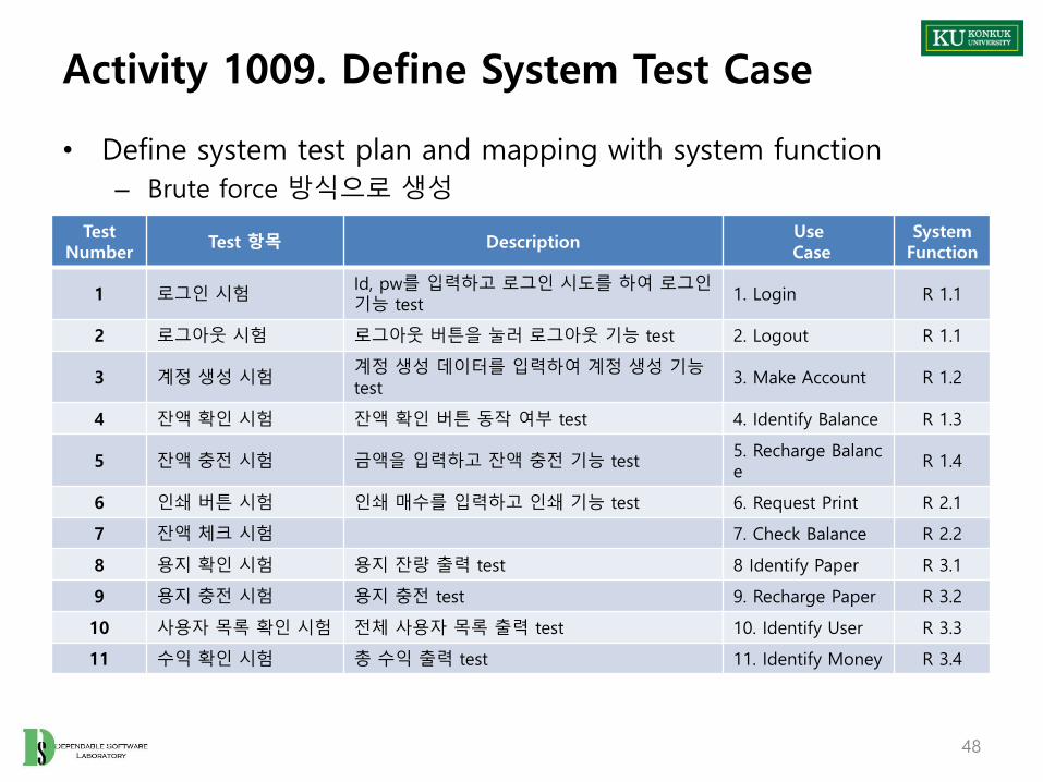
• Define system test plan and mapping with system function
– Brute force 방식으로 생성
48
Test Number
Test 항목 DescriptionUseCase
System Function
1 로그인 시험Id, pw를 입력하고 로그인 시도를 하여 로그인기능 test
1. Login R 1.1
2 로그아웃 시험 로그아웃 버튼을 눌러 로그아웃 기능 test 2. Logout R 1.1
3 계정 생성 시험계정 생성 데이터를 입력하여 계정 생성 기능test
3. Make Account R 1.2
4 잔액 확인 시험 잔액 확인 버튼 동작 여부 test 4. Identify Balance R 1.3
5 잔액 충전 시험 금액을 입력하고 잔액 충전 기능 test5. Recharge Balance
R 1.4
6 인쇄 버튼 시험 인쇄 매수를 입력하고 인쇄 기능 test 6. Request Print R 2.1
7 잔액 체크 시험 7. Check Balance R 2.2
8 용지 확인 시험 용지 잔량 출력 test 8 Identify Paper R 3.1
9 용지 충전 시험 용지 충전 test 9. Recharge Paper R 3.2
10 사용자 목록 확인 시험 전체 사용자 목록 출력 test 10. Identify User R 3.3
11 수익 확인 시험 총 수익 출력 test 11. Identify Money R 3.4
Stage 2000. Build
Konkuk University 49
Plan andElaboration
Build Deployment1000 2000 3000

6 Phases of ‘Build’ Stage
50
Cycle 1 Cycle 2 Cycle n...
Plan andElaboration
Build Deployment1000 2000 3000
2100 2200 2n00
Revise Plan
2110 Sync.Artifacts
2120
Analyze
2130
Design
2140
Construct
2150
Test
2160

Phase 2010. Revise Plan
Revise Plan
2110 Sync.Artifacts
2120
Analyze
2130
Design
2140
Construct
2150
Test
2160

Phase 2010. Revise Plan
• Description
– Correct and enhance the project plan and requirement definition based on the intermediate deliverables
– Input : intermediate deliverables
– Output : A refined project plan, a refined requirement specification
• Steps
52
Revise Plan2110
Sync. Artifacts2120

Phase 2020. Synchronize Artifacts
Revise Plan
2110 Sync.Artifacts
2120
Analyze
2130
Design
2140
Construct
2150
Test
2160

Phase 2020. Synchronize Artifacts
• Description– Configure and manage various types of artifacts (Project Repository)
– Control versions and variations
– Input :
– Output :
• Steps
54
Revise Plan2110 Synchronize
Artifacts
2120Analyze
2130

Phase 2030. Analyze
Revise Plan
2110 Sync.Artifacts
2120
Analyze
2130
Design
2140
Construct
2150
Test
2160

Phase 2030. Analyze
• Phase 2030 Activities
56
Refine Use Case Diagrams
2132
Define System Sequence Diagrams
2135
DefineDomain Model
2133
Define Operation Contracts
2136
Define State Diagrams
2137
Define EssentialUse Cases
2131
RefineGlossary
2134
a
b
Analyze2130
a. if not yet doneb. ongoingc. optional
cRefine System
Test Case
2138 Analyze (2030)Traceability Analysis
2139

Activity 2031. Define Essential Use Cases
• Description– Add event flows to business use case(high-level) descriptions
– Input : business use case descriptions (activity 1006)
– Output : An essential use case descriptions
– Standard applied : expanded use case format
57
Refine Use Case Diagrams
2132Define EssentialUse Cases
2131a

Activity 2031. Define Essential Use Cases
• Step
1. Select each use case from business use cases
2. Identify system functions related to the selected use case from requirements specification
3. Identify related use cases to the selected use case from business use cases
4. Identify courses of events for each use case from the requirements specification• Typical courses of events (main event flow)
• Alternative courses of events
• Exceptional courses of events
5. Write essential use cases based on typical and alternative courses of events flows by applying expanded use case format.
58

Activity 2031. Define Essential Use Cases
• Expanded Use Case Format
– Use case: Use Case Name
– Actors: Actor Name
– Purpose: The purpose of Use Case
– Overview: The overview of Use Case
– Type: Primary, Secondary, or Optional
– Cross References: System functions in Req. Spec
– Pre-Requisites: An essential pre-condition
– Typical Courses of Events: Abstract scenario about the flow of events
– Alternative Courses of Events:
– Exceptional Courses of Events: define exceptional cases
59
Activity 2031. Define Essential Use Cases
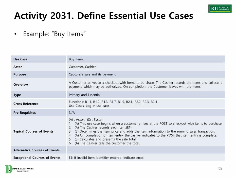
• Example: “Buy Items”
60
Use Case Buy Items
Actor Customer, Cashier
Purpose Capture a sale and its payment
OverviewA Customer arrives at a checkout with items to purchase. The Cashier records the items and collects a payment, which may be authorized. On completion, the Customer leaves with the items.
Type Primary and Essential
Cross ReferenceFunctions: R1.1, R1.2, R1.3, R1.7, R1.9, R2.1, R2.2, R2.3, R2.4Use Cases: Log In use case
Pre-Requisites N/A
Typical Courses of Events
(A) : Actor, (S) : System1. (A) This use case begins when a customer arrives at the POST to checkout with items to purchase.2. (A) The Cashier records each item.(E1)3. (S) Determines the item price and adds the item information to the running sales transaction.4. (A) On completion of item entry, the cashier indicates to the POST that item entry is complete.5. (S) Calculates and presents the sale total.6. (A) The Cashier tells the customer the total.
Alternative Courses of Events …
Exceptional Courses of Events E1: If invalid item identifier entered, indicate error.

Activity 2032. Refine Use Case Diagrams
• Description– Validate and modify the ‘Business Use-Case Diagram’
– Input : business use case model, essential use case descriptions
– Output : A refined use case diagram
– Standard applied : UML’s use case diagram
• Step1. Review business use case diagrams according to essential use case
descriptions
2. Refine use case diagrams by adding or refining use cases and relationships
61
Refine Use Case Diagrams
2132 DefineDomain Model
2133Define EssentialUse Cases
2131

Activity 2033. Define Domain Model
• Description
– Define domain concept model by reviewing input artifacts
– Input : essential use case descriptions, business concept model
– Output : A conceptual class diagram
– Standard applied : UML’s use case diagram
• What is domain model?– A representation of conceptual classes identified from a real world
– Illustrates meaningful conceptual classes in a problem domain.
– Conceptual models
– Widely used as a source of inspiration for designing software objects.
62
DefineDomain Model
2133 RefineGlossary
2134Refine Use Case Diagrams
2132 b

Activity 2033. Define Domain Model
• Step
1. List concepts(domain class) from use cases or business concept model
• Guideline 1
– Identify concepts by making a list of candidate concepts from the ‘Concept Category List’
• Guideline 2
– Identity the noun and noun phrases in expanded use cases description and consider them as candidate concepts or attributes
63

Activity 2033. Define Domain Model
• By using guideline 1
– ‘Concept Category List’ may contain many common categories that are usually worth to consider
64
Concept Category Examples
Physical or tangible objects POST
Specifications, designs, or descriptions of things Product Specification
Places Store
TransactionsSalePayment
Transaction line items Sales Line Item
Roles of people Cashier
Containers of other things Store
Things in a container Item
Other computer or electro-mechanical systems external to our system
Credit Card Authorization System
… …
Activity 2033. Define Domain Model
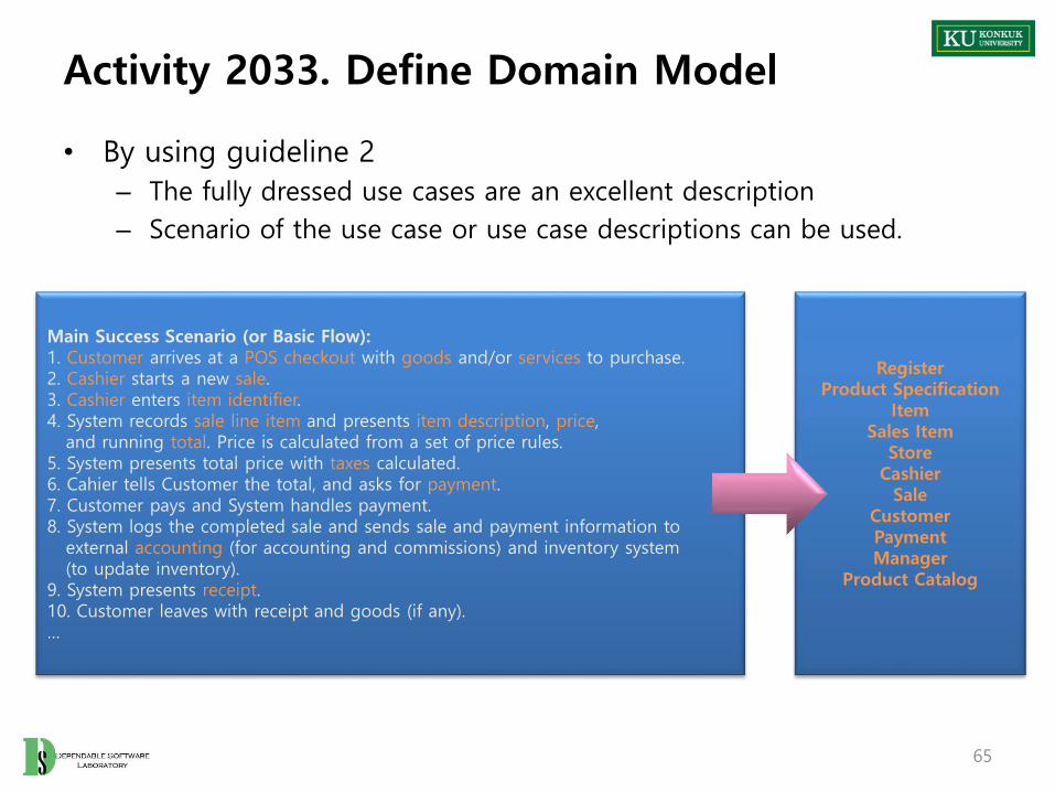
• By using guideline 2
– The fully dressed use cases are an excellent description
– Scenario of the use case or use case descriptions can be used.
65
Main Success Scenario (or Basic Flow):1. Customer arrives at a POS checkout with goods and/or services to purchase.2. Cashier starts a new sale.3. Cashier enters item identifier.4. System records sale line item and presents item description, price,
and running total. Price is calculated from a set of price rules.5. System presents total price with taxes calculated.6. Cahier tells Customer the total, and asks for payment.7. Customer pays and System handles payment.8. System logs the completed sale and sends sale and payment information to
external accounting (for accounting and commissions) and inventory system(to update inventory).
9. System presents receipt.10. Customer leaves with receipt and goods (if any).…
RegisterProduct Specification
ItemSales Item
StoreCashier
SaleCustomerPaymentManager
Product Catalog

Activity 2033. Define Domain Model
2. Assign class names into concepts
• Use the existing names in the domain
• Do not add things that are not there
3. Identify associations according to association categories
66
Association Category Identified Associations
A is a physical part of B Drawer – POST
A is a logical part of B SalesLineItem – Sale
A is physically contained in/on BPOST – StoreItem – Shelf
A is logically contained in B ItemDescription – Catalog
A is a description for B ItemDescription – Item
A is a line item of a transaction or report B SalesLineItem – Sale
A is known/logged/recorded/reported/captured in B Sale – POST
A is a member of B Cashier –Store
A is an organizational submit of B Department – Store
… …
Activity 2033. Define Domain Model
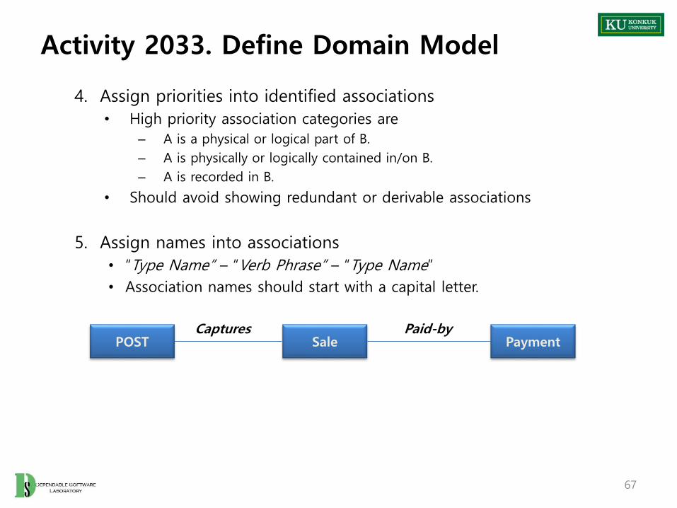
4. Assign priorities into identified associations
• High priority association categories are
– A is a physical or logical part of B.
– A is physically or logically contained in/on B.
– A is recorded in B.
• Should avoid showing redundant or derivable associations
5. Assign names into associations
• “Type Name” – “Verb Phrase” – “Type Name”
• Association names should start with a capital letter.
67
POST Sale PaymentPaid-byCaptures

Activity 2033. Define Domain Model
6. Add multiplicity into the ends of an association
7. Identify attributes by reading
• requirement specifications, current use cases under consideration, simplification, clarification, and assumption documents
• Attributes should be simple attributes or pure data values
– Boolean, Date, Number, String, Time
– Address, Color, Geometrics(Point, Rectangle,…), Phone Number, Social Security Number, Universal Product Code(UPC), ZIP or postal codes, Enumerated types.
68
Store ItemStocks
1 *
Cashier
namecurrentPOST
POST
number
Cashier
name 1
Uses
1
Not a “simple” attribute

Activity 2033. Define Domain Model
8. Draw them in a conceptual class diagram
69
SlaesLineItem
quantity
Item
Sale
datetime
Store
addressname
1..*
Contained-in Stocked-in1
1
Records-sale-of
*
1
0..1

Activity 2034. Refine Glossary
• Description
– Lists and refines all the terms in order to improve communication and reduce the risk of misunderstanding
– Input : term dictionary, essential use case descriptions, conceptual class diagram
– Output : A refined term dictionary
• Step1. Refine terms defined in the Plan and Elaborate Phase(use cases, attributes,
concept, etc.) during development cycle.
2. Record terms as following format:
70
RefineGlossary
2134 Define System Sequence Diagrams
2135DefineDomain Model
2133 b
Term Category Comments
Payment Concept (Class) a cash payment
… … …

Activity 2035. Define System Sequence Diagrams
• Description
– Illustrates events from actors to systems.
– To investigate the system to build
– Input : essential use case descriptions, use case diagram
– Output : A sequence diagram
71
Define SystemSequence Diagrams
2135 Define Operation Contracts
2136RefineGlossary
2134 b

Activity 2035. Define System Sequence Diagrams
• What is a system sequence diagram(SSD) ?
– A picture that shows the events that external actors generate, their orders, and inter-system events
– All systems are treated as a black box
– The emphasis of the diagram is events that cross the system boundary from actors to systems
– SSDs should be defined for
• Main success scenarios
• Frequent, complex, or alternative scenarios
72

Activity 2035. Define System Sequence Diagrams
• Step
1. Draw a black box representing the system based on a use case
2. Identify each actor that directly operate on the system from the typical(normal) course of events in a use case
• Draw a line for each actor
73
:System
Actor 1 Actor 2

Activity 2035. Define System Sequence Diagrams
3. Determine system boundary
- Hardware/software boundary of a device or computer system
- Department of an organization or Entire organization
• Identify the system(external) events that each actor generates by according to typical course of events in a use case
• Name system events
- Should be expressed at the level of intent rather than of the physics
- Name a system event with a verb and an objective like “enterItem”
74
:System
Cashier
System Boundary
enterItem(UPC, quantity)
endSale( )
makePayment(amount)
Scenario: Buy Items

Activity 2035. Define System Sequence Diagrams
4. Include the use case text which corresponds to system event to the left of the system sequence diagram
75
Cashier
enterItem(UPC, quantity)
endSale( )
makePayment(amount)
USE CASE: Buy Items
Typical Course of Events
1. This use case begins when a Customer arrives at the POST tocheckout with items to purchase.
2. The Cashier records the universal product code(UPC) fromeach item. If there is more thanone of the same item, the Cashier canenter the quantity as well.
3. System determines the item priceand adds the item information to the running sales transaction.The description and price of thecurrent item are displayed.
:System

Activity 2036. Define Operation Contracts
• Description
– Define contracts for system operations
– Input : system sequence diagram, conceptual class diagram
– Output : Operation Contracts
• What is a contract?
– A document that describes what an operation commits to achieve
– Written for each system operation to describe its behavior
– System Operation Contract : Describes changes in states of overall
system when a system operation is invoked
76
Define Operation Contracts
2136 Define State Diagrams
2137Define SystemSequence Diagrams
2135 c
Activity 2036. Define Operation Contracts
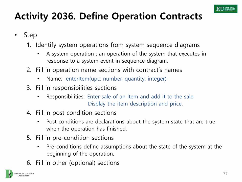
• Step
1. Identify system operations from system sequence diagrams
• A system operation : an operation of the system that executes in
response to a system event in sequence diagram.
2. Fill in operation name sections with contract’s names
• Name: enterItem(upc: number, quantity: integer)
3. Fill in responsibilities sections
• Responsibilities: Enter sale of an item and add it to the sale.
Display the item description and price.
4. Fill in post-condition sections
• Post-conditions are declarations about the system state that are true
when the operation has finished.
5. Fill in pre-condition sections
• Pre-conditions define assumptions about the state of the system at the
beginning of the operation.
6. Fill in other (optional) sections
77

Activity 2036. Define Operation Contracts
• Operation Contracts Format
78
Name Name of operation, and parameters
Responsibilities An informal description of the responsibilities that the operation must fill
Type Name of type(concept, software class, interface)
Cross References System function reference numbers, use cases, etc.
Notes Design notes, algorithms, and so on.
Exceptions Exceptional cases
OutputNon-UI outputs, such as messages or records that are sent outside of the system
Pre-conditionsAssumptions that the state of the system before execution of the operation
Post-conditions The state of the system after completion of the operation
…
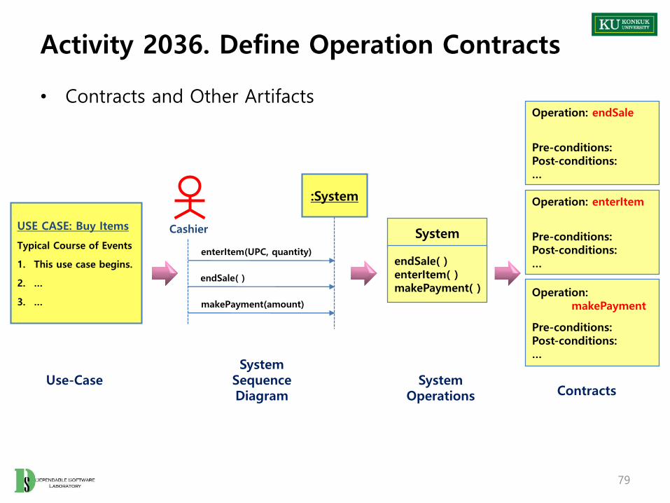
Activity 2036. Define Operation Contracts
• Contracts and Other Artifacts
79
USE CASE: Buy Items
Typical Course of Events
1. This use case begins.
2. …
3. …
:System
Cashier
enterItem(UPC, quantity)
endSale( )
makePayment(amount)
System
endSale( )enterItem( )makePayment( )
Operation: endSale
Pre-conditions:Post-conditions:…
Operation: enterItem
Pre-conditions:Post-conditions:…
Operation: makePayment
Pre-conditions:Post-conditions:…
ContractsSystem
OperationsUse-Case
SystemSequenceDiagram
Activity 2037. Define State Diagrams
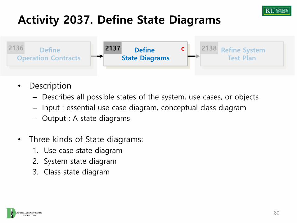
• Description
– Describes all possible states of the system, use cases, or objects
– Input : essential use case diagram, conceptual class diagram
– Output : A state diagrams
• Three kinds of State diagrams:
1. Use case state diagram
2. System state diagram
3. Class state diagram
80
Define State Diagrams
2137 Refine SystemTest Plan
2138DefineOperation Contracts
2136 c

Activity 2037. Define State Diagrams
• Event
– A significant or noteworthy occurrence
– Ex) a telephone receiver is taken off the hook
• State
– Condition of an object at a moment in time
– Ex) a telephone is in the state of being “idle” after the receiver is
placed on the hook and until it is taken off the hook
• Transition
– A relationship between two states that indicates that when an event
occurs and the object moves from one state to another
– Ex) when the event “off hook” occurs, transition occurs from the “idle”
to “active” state
81

Activity 2037. Define State Diagrams
• Use Case State Diagram
– A state diagram that depicts the overall system events and their sequence within a use case
82
EnteringItemsWaitingForSale
makePayment
endSale
enterItem
Use Case: Buy Items
enterItem
WaitingForPayment

Activity 2037. Define State Diagrams
• Class State Diagram
– A state diagram that depicts state changes of a class across all the use cases
– Identify a class from interaction diagram
– A union of all the use case state diagrams
83
:Sale
:ProductCatalog
:POST
1: [new sale] create( )
2: spec := specification(upc)
3: makeLineItem(spec,qty)
enterItemEnteringSale
WaitingForSale
enterItem(upc,qty)
“POST” Class
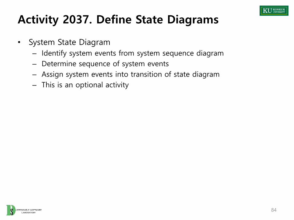
Activity 2037. Define State Diagrams
• System State Diagram
– Identify system events from system sequence diagram
– Determine sequence of system events
– Assign system events into transition of state diagram
– This is an optional activity
84

Activity 2038. Refine System Test Case
• Description
– Refine system test plan by using additional information
– Input : essential use case description, system test plan, sequence diagram
– Output : refined system test plan
• Step :
– Refine the results of activity 1009 with the results of analyze process
85
Define State Diagrams
2137 Refine SystemTest Case
2138c Analyze (2030)Traceability Analysis
2139

Activity 2039. Analyze (2030) Traceability Analysis
• Description
– Analysis the connection of results which are the results of analyze (2030) step
• Identify the connection of use cases, system sequence diagram and operation contracts
– Input : Essential use case description, sequence diagram
operation contracts
– Output : Traceability analysis result
• Step
– Writing the relations about the results of each step
86
Refine SystemTest Case
2138 Analyze (2030)Traceability Analysis
2139

Activity 2039. Analyze (2030) Traceability Analysis
• Example of Analyze traceability
87

Phase 2030. Analyze
-Case Study-
Revise Plan
2110 Sync.Artifacts
2120
Analyze
2130
Design
2140
Construct
2150
Test
2160

Phase 2030. Analyze
• Phase 2030 Activities
89
Refine Use Case Diagrams
2132
Define System Sequence Diagrams
2135
DefineDomain Model
2133
Define Operation Contracts
2136
Define State Diagrams
2137
Define EssentialUse Cases
2131
RefineGlossary
2134
a
b
Analyze2130
a. if not yet doneb. ongoingc. optional
cRefine System
Test Plan
2138 Analyze (2030)Traceability Analysis
2139

Activity 2031. Define Essential Use Cases
90
Use Case Login
Actor User, Manager
Purpose User와 manager가 시스템에 접속하기 위해 로그인 할 수 잇도록 한다.
OverviewID/PW 를 입력 받아 계정과 비밀번호가 일치하는 경우 user or manager로로그인 한다.일치하는 계정이 없는 경우 로그인 되지 않는다.
Type Primary
Cross ReferenceFunctions: R 1.1, Use Cases:
Pre-Requisites N/A
Typical Courses of Events
(A) : Actor, (S) : System1. (A) : ID/PW를 입력 한다.2. (A) : 로그인을 요청한다.3. (S) : 일치하는 계정이 있는지 검사 후 존재 하는 경우 user or manage로
접속 승인 한다.
Alternative Courses of Events
…
Exceptional Courses of Events
E1. 일치하는 계정이 없는 경우 접속되지 않는다.

Activity 2031. Define Essential Use Cases
91
Use Case Logout
Actor User, Manager
Purpose 접속된 User or Manager의 접속을 종료한다.
OverviewLogout 버튼을 누르면 접속된 user or manager의 접속을 종료하고 초기화면으로 돌아간다.
Type Primary
Cross ReferenceFunctions: R 1.1Use Cases:
Pre-Requisites Login이 선행 되어야 한다.
Typical Courses of Events
(A) : Actor, (S) : System1. (A) : 로그아웃을 요청 한다.2. (S) : 시스템 접속을 종료하고 초기화면으로 돌아간다.
Alternative Courses of Events
…
Exceptional Courses of Events
N/A

Activity 2031. Define Essential Use Cases
92
Use Case Make Account
Actor User
Purpose 새로운 사용자 계정을 생성한다.
Overview생성할 계정의 id/pw를 입력 후 생성 버튼을 눌러 새로운 사용자 계정을 생성 할 수 있다. 새로 생성한 계정은 동일한 id가 없는 경우에만 생성 된다.
Type Primary
Cross ReferenceFunctions: R 1.2Use Cases:
Pre-Requisites N/A
Typical Courses of Events
(A) : Actor, (S) : System1. (A) : 계정 생성을 요청한다.2. (A) : ID/PW를 입력 한다.3. (S) : ID/PW를 확인 하여 기존 사용자와 비교 한다.4. (S) : 계정 생성에 적합한 경우 사용자 계정을 생성 한다.
Alternative Courses of Events
…
Exceptional Courses of Events
E1. 동일한 id를 가진 계정이 이미 존재하는 경우 생성하지 않는다.

Activity 2031. Define Essential Use Cases
93
Use Case Identify Balance
Actor User
Purpose 사용자 계정에 남아있는 잔액을 확인 한다.
Overview 사용자의 잔액 확인 요청 시 남아있는 잔액을 확인하여 출력 한다.
Type Primary
Cross ReferenceFunctions: R 1.3Use Cases:
Pre-Requisites 사용자로 login이 선행 되어야 한다.
Typical Courses of Events
(A) : Actor, (S) : System1. (A) : 잔액 확인을 요청 한다. 2. (S) : 해당 사용자의 잔액을 확인 후 출력 한다.
Alternative Courses of Events
…
Exceptional Courses of Events

Activity 2031. Define Essential Use Cases
94
Use Case Recharge Balance
Actor User
Purpose 해당 사용자 계정에 잔액을 충전 한다.
Overview 입력 받은 금액 만큼 해당 사용자 계정에 잔액을 충전 한다.
Type Primary
Cross ReferenceFunctions: R 1.4Use Cases:
Pre-Requisites 사용자로 login이 선행 되어야 한다.
Typical Courses of Events
(A) : Actor, (S) : System1. (A) : 금액을 입력 한다. 2. (A) : 잔액 충전을 요청한다.3. (S) : 입력 받은 금액 만큼 사용자 계정에 잔액을 충전 한다.
Alternative Courses of Events
…
Exceptional Courses of Events
Activity 2031. Define Essential Use Cases
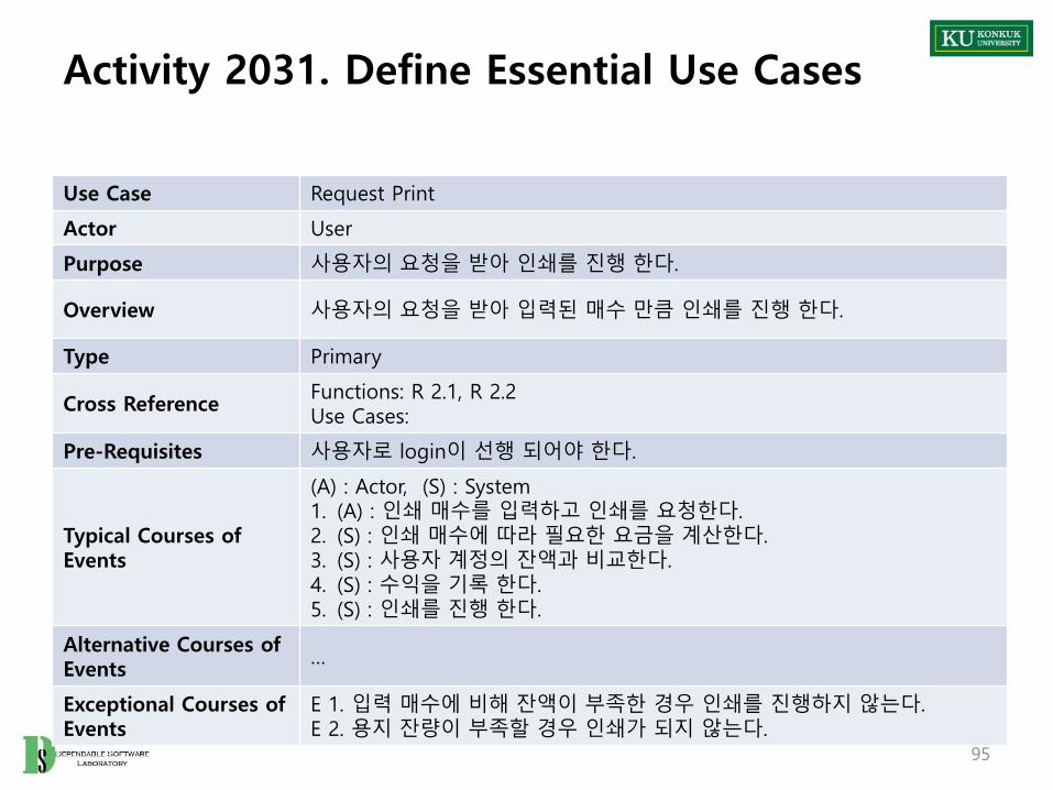
95
Use Case Request Print
Actor User
Purpose 사용자의 요청을 받아 인쇄를 진행 한다.
Overview 사용자의 요청을 받아 입력된 매수 만큼 인쇄를 진행 한다.
Type Primary
Cross ReferenceFunctions: R 2.1, R 2.2Use Cases:
Pre-Requisites 사용자로 login이 선행 되어야 한다.
Typical Courses of Events
(A) : Actor, (S) : System1. (A) : 인쇄 매수를 입력하고 인쇄를 요청한다.2. (S) : 인쇄 매수에 따라 필요한 요금을 계산한다.3. (S) : 사용자 계정의 잔액과 비교한다.4. (S) : 수익을 기록 한다. 5. (S) : 인쇄를 진행 한다.
Alternative Courses of Events
…
Exceptional Courses of Events
E 1. 입력 매수에 비해 잔액이 부족한 경우 인쇄를 진행하지 않는다.E 2. 용지 잔량이 부족할 경우 인쇄가 되지 않는다.

Activity 2031. Define Essential Use Cases
96
Use Case Check Balance
Actor Event-based
Purpose 인쇄 진행 시 잔액과 필요 요금을 확인 및 비교 한다.
Overview사용자의 요청에 의해 인쇄 진행 시 시스템의 요청을 받아 필요 요금과 잔액을 체크한다.
Type Primary
Cross ReferenceFunctions: R 2.1, R 2.2Use Cases: Request Print
Pre-Requisites 시스템에 인쇄 요청 후에 동작 한다.
Typical Courses of Events
(A) : Actor, (S) : System1. (S - A) : 사용자의 인쇄 요청을 받은 시스템이 잔액 확인을 요청한다.2. (S) : 사용자 계정의 잔액과 필요한 요금비교를 통해 인쇄 가능 여부를 체
크 한다.
Alternative Courses of Events
…
Exceptional Courses of Events
E 1. 잔액이 부족한 경우 인쇄 불가 신호를 보낸다.

Activity 2031. Define Essential Use Cases
97
Use Case Identify Paper
Actor Manager
Purpose 시스템 관리자가 프린터에 남은 용지를 확인 할 수 있다.
Overview 시스템 관리자의 요청에 따라 프린터에 남은 용지 잔량을 확인한다.
Type Primary
Cross ReferenceFunctions: R 3.1Use Cases:
Pre-Requisites Manager로 로그인 되어 있어야 한다.
Typical Courses of Events
(A) : Actor, (S) : System1. (A) : 시스템에 용지 잔량 확인을 요청 한다.2. (s) : 남은 용지 잔량을 확인 후 출력 한다.
Alternative Courses of Events
…
Exceptional Courses of Events

Activity 2031. Define Essential Use Cases
98
Use Case Identify Paper
Actor Manager
Purpose 시스템 관리자가 프린터에 남은 용지를 확인 할 수 있다.
Overview 시스템 관리자의 요청에 따라 프린터에 남은 용지 잔량을 확인한다.
Type Primary
Cross ReferenceFunctions: R 3.1Use Cases:
Pre-Requisites Manager로 로그인 되어 있어야 한다.
Typical Courses of Events
(A) : Actor, (S) : System1. (A) : 시스템에 용지 잔량 확인을 요청 한다.2. (s) : 남은 용지 잔량을 확인 후 출력 한다.
Alternative Courses of Events
…
Exceptional Courses of Events

Activity 2031. Define Essential Use Cases
99
Use Case Recharge Paper
Actor Manager
Purpose 시스템 관리자의 요청에 따라 시스템의 용지 잔량을 충전 한다.
Overview 시스템 관리자가 요청한 매수 만큼 시스템의 용지 잔량을 충전 한다.
Type Primary
Cross ReferenceFunctions: R 3.2Use Cases:
Pre-Requisites Manager로 로그인 되어 있어야 한다.
Typical Courses of Events
(A) : Actor, (S) : System1. (A) : 충전할 용지 매수를 입력 한다.2. (A) : 용지 충전을 요청 한다. 3. (s) : 요청 받은 수 만큼의 용지를 충전 한다.
Alternative Courses of Events
…
Exceptional Courses of Events
E 1. 입력 받은 매수가 없는 경우 충전이 되지 않는다.
Activity 2031. Define Essential Use Cases
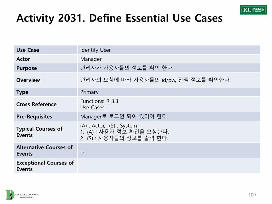
100
Use Case Identify User
Actor Manager
Purpose 관리자가 사용자들의 정보를 확인 한다.
Overview 관리자의 요청에 따라 사용자들의 id/pw, 잔액 정보를 확인한다.
Type Primary
Cross ReferenceFunctions: R 3.3Use Cases:
Pre-Requisites Manager로 로그인 되어 있어야 한다.
Typical Courses of Events
(A) : Actor, (S) : System1. (A) : 사용자 정보 확인을 요청한다. 2. (S) : 사용자들의 정보를 출력 한다.
Alternative Courses of Events
…
Exceptional Courses of Events

Activity 2031. Define Essential Use Cases
101
Use Case Identify Money
Actor Manager
Purpose 총 수익을 확인 한다.
Overview 관리자의 요청에 따라 지금까지의 총 수익을 확인 한다.
Type Primary
Cross ReferenceFunctions: R 3.4Use Cases:
Pre-Requisites Manager로 로그인 되어 있어야 한다.
Typical Courses of Events
(A) : Actor, (S) : System1. (A) : 수익 확인을 요청 한다. 2. (S) : 지금까지의 누적 수익을 출력 한다.
Alternative Courses of Events
…
Exceptional Courses of Events

Activity 2033. Define Domain Model
• List concepts from use cases or business concept model
102
Account Balance Print
Manage Access login
logout Charge

Activity 2033. Define Domain Model
• Assign class names into concepts
• Draw a conceptual class diagram
• Identify and add associations
103
User PrinterManager
AccountManager
Association Category
Associations
A has B
ManagementSystem - PrinterManagementSystem - AccountAccount – UserAccount – Manager
ManagementSystem

Activity 2033. Define Domain Model
• Add Roles and Multiplicity
104
User
Account
AccountManager
ManagementSystem
ManagerAccountManager
PrinterManagement
System
Has
Has
Has
Has
1 0 .. *
1 1
1 1
1 1

Activity 2033. Define Domain Model
• Draw a conceptual class diagram and add attributes
105
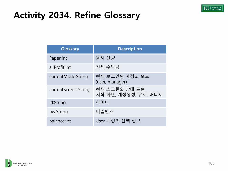
Activity 2034. Refine Glossary
106
Glossary Description
Paper:int 용지 잔량
allProfit:int 전체 수익금
currentMode:String 현재 로그인된 계정의 모드(user, manager)
currentScreen:String 현재 스크린의 상태 표현시작 화면, 계정생성, 유저, 매니저
id:String 아이디
pw:String 비밀번호
balance:int User 계정의 잔액 정보

Activity 2035. Define System Sequence Diagrams
107
Use CaseName of
Actor-Activated Event
1. Login enterInfo
reqLogin
2. Logout reqLogout
3. Make Account reqMakeAcc
enterAccInfo
reqAccount
4. Identify Balance reqBalance
5. Recharge Balance enterFee
reqRecharge
6. Request Print enterSheet
reqPrint
8 Identify Paper req Identify Paper
9. Recharge Paper enterPaperNum
reqCharge
10. Identify User reqUserInfo
11. Identify Money reqMoneyInfo

Activity 2035. Define System Sequence Diagrams
108
User
SystemUse Case : Login
1. 사용자가 id, pw를 입력한다.
2. 사용자가 로그인을 요청한다.
3. 계정과 일치할 경우 로그인을 승인 한다.
enterInfo(id, pw)
ReqLogin()

Activity 2035. Define System Sequence Diagrams
109
User
SystemUse Case : Logout
1. 사용자가 logout을 요청한다.
2. 시스템에서 초기화 후 접속 종료 한다.
reqLogout()

Activity 2035. Define System Sequence Diagrams
110
User
SystemUse Case : make Account
1. 사용자가 계정 생성을 요청 한다.
2. 사용자가 생성할 계정의정보를 입력 한다.
3. 정보 입력 후 승인을 요청 한다.
4. 시스템이 계정 정보 확인후 계정을 생성 한다.
reqMakeAcc()
enterAccInfo(id, pw)
reqAccount()

Activity 2035. Define System Sequence Diagrams
111
User
SystemUse Case : Identify Balance
1. 사용자가 잔액 정보 확인을 요청 한다.
2. 시스템이 해당 사용자의정보를 출력 한다.
reqBalance()
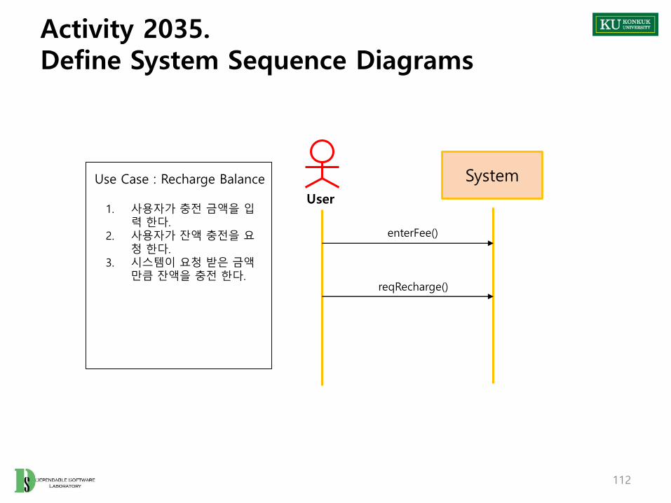
Activity 2035. Define System Sequence Diagrams
112
User
SystemUse Case : Recharge Balance
1. 사용자가 충전 금액을 입력 한다.
2. 사용자가 잔액 충전을 요청 한다.
3. 시스템이 요청 받은 금액만큼 잔액을 충전 한다.
enterFee()
reqRecharge()

Activity 2035. Define System Sequence Diagrams
113
User
SystemUse Case : Request Print
1. 사용자가 인쇄 매수를 입력 한다.
2. 사용자가 출력을 요청 한다.
3. 시스템이 잔액 확인 후인쇄를 진행 한다.
enterSheet()
reqPrint()

Activity 2035. Define System Sequence Diagrams
114
Manager
SystemUse Case : Identify Paper
1. 관리자가 용지 잔량 확인을 요청 한다.
2. 시스템이 남은 용지 잔량을 출력 한다.
req Identify Paper()
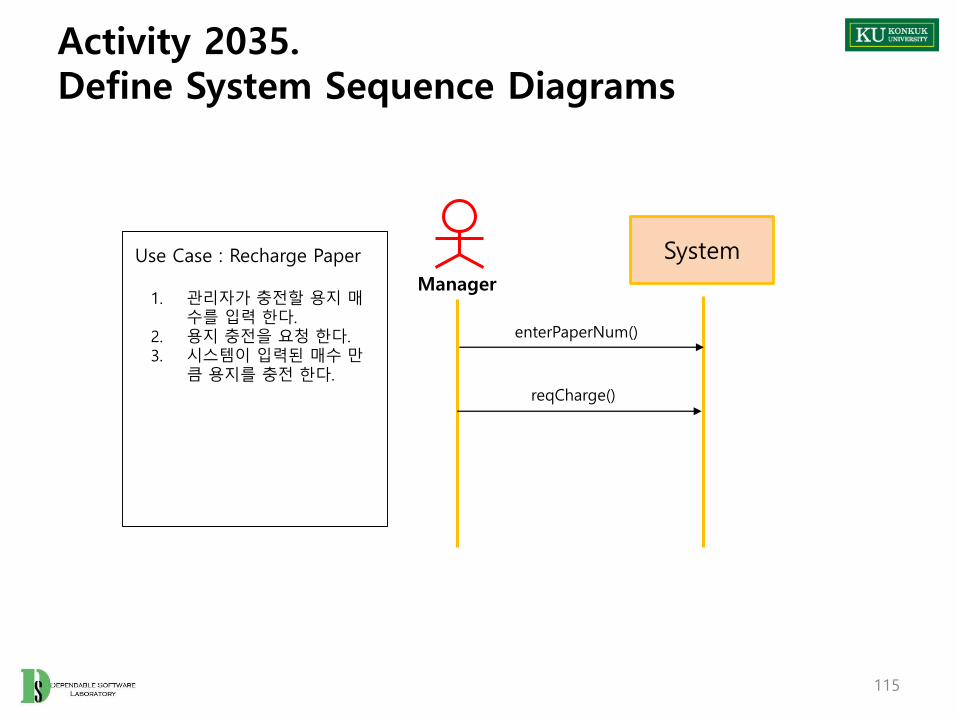
Activity 2035. Define System Sequence Diagrams
115
Manager
SystemUse Case : Recharge Paper
1. 관리자가 충전할 용지 매수를 입력 한다.
2. 용지 충전을 요청 한다.3. 시스템이 입력된 매수 만
큼 용지를 충전 한다.
enterPaperNum()
reqCharge()

Activity 2035. Define System Sequence Diagrams
116
Manager
SystemUse Case : Identify User
1. 관리자가 사용자 정보를요청 한다.
2. 시스템이 사용자들의 정보를 출력 한다.
reqUserInfo()

Activity 2035. Define System Sequence Diagrams
117
Manager
SystemUse Case : Identify Money
1. 관리자가 수익정보를 요청 한다.
2. 시스템이 전체 수익 정보를 출력 한다.
reqMoneyInfo()

Activity 2036. Define Operation Contracts
• Identify system operations from system sequence diagrams
118
Use CaseName of
Actor-Activated EventSystem Operations
1. Login 1:enterInfo() 1:enterInfo()
2:reqLogin() 2:reqLogin()
2. Logout 3:reqLogout() 3:reqLogout()
3. Make Account 4:reqMakeAcc() 4:reqMakeAcc()
5:enterAccInfo() 5:enterAccInfo()
6:reqAccount() 6:reqAccount()
4. Identify Balance 7:reqBalance() 7:reqBalance()
5. Recharge Balance 8:enterFee() 8:enterFee()
9:reqRecharge() 9:reqRecharge()
6. Request Print 10:enterSheet() 10:enterSheet()
11:reqPrint() 11:reqPrint()
8 Identify Paper 12:req Identify Paper() 12:reqPaperIdentify()
9. Recharge Paper 13:enterPaperNum() 13:enterPaperNum()
14:reqCharge() 14:reqCharge()
10. Identify User 15:reqUserInfo() 15:reqUserInfo()
11. Identify Money 16:reqMoneyInfo() 16:reqMoneyInfo()

Activity 2036. Define Operation Contracts
• Fill contracts according to the format
119
Name enterInfo
Resposibilities id, pw를 입력 받는다.
Type System
Cross References R 1.1
Notes
Exceptions N/A
Output N/A
Pre-Conditions N/A
Post-Conditions id, pw 정보를 화면에 출력 한다.

Activity 2036. Define Operation Contracts
• Fill contracts according to the format
120
Name reqLogin
Resposibilities id, pw를 확인하고 로그인을 시도 한다.
Type System
Cross References R 1.1
Notes
Exceptionsid, pw 가 일치 하지 않으면 오류 메시지를 출력하고 로그인 승인 X
Output N/A
Pre-Conditions N/A
Post-ConditionsAccount 의 user, manager instance와 id, pw 비교일치할 경우 해당 계정으로 로그인 후 화면 전환

Activity 2036. Define Operation Contracts
• Fill contracts according to the format
121
Name reqLogout
Resposibilities 시스템에서 로그아웃 한다
Type System
Cross References R 1.1
Notes
Exceptions 로그인 된 상태 이어야 한다.
Output N/A
Pre-Conditions N/A
Post-Conditions 시스템에서 로그아웃 된다.

Activity 2036. Define Operation Contracts
• Fill contracts according to the format
122
Name reqMakeAcc
Resposibilities 사용자 계정 생성을 요청 한다.
Type System
Cross References R 1.2
Notes
Exceptions N/A
Output N/A
Pre-Conditions N/A
Post-Conditions 사용자 계정 생성 상태가 된다.

Activity 2036. Define Operation Contracts
• Fill contracts according to the format
123
Name enterAccInfo
Resposibilities 생성할 사용자 계정 정보를 입력 한다.
Type System
Cross References R 1.2
Notes
Exceptions N/A
Output N/A
Pre-Conditions N/A
Post-Conditions 입력한 정보를 화면에 출력 한다.

Activity 2036. Define Operation Contracts
• Fill contracts according to the format
124
Name reqAccount
Resposibilities 정보대로 계정 생성을 요청 한다.
Type System
Cross References R 1.2
Notes
Exceptions 동일한 id가 존재할 경우 생성하지 않는다.
Output User class의 instance
Pre-Conditions N/A
Post-Conditions 사용자 계정을 생성 한다.

Activity 2036. Define Operation Contracts
• Fill contracts according to the format
125
Name reqBalance
Resposibilities 잔액 정보 확인을 요청 한다.
Type System
Cross References R 1.3
Notes
Exceptions N/A
Output N/A
Pre-Conditions 사용자 로그인 상태 이어야 한다.
Post-Conditions 잔액 정보를 출력 한다.

Activity 2036. Define Operation Contracts
• Fill contracts according to the format
126
Name enterFee
Resposibilities 충전할 금액을 입력 한다.
Type System
Cross References R 1.4
Notes
Exceptions N/A
Output N/A
Pre-Conditions 사용자 로그인 상태 이어야 한다.
Post-Conditions 입력한 금액을 출력 한다.

Activity 2036. Define Operation Contracts
• Fill contracts according to the format
127
Name reqRecharge
Resposibilities 잔액 충전을 요청 한다.
Type System
Cross References R 1.4
Notes
Exceptions N/A
Output User.balance 변경
Pre-Conditions사용자 로그인 상태 이어야 한다.입력된 금액이 있어야 한다.
Post-Conditions 사용자 계정에 금액을 충전 한다.

Activity 2036. Define Operation Contracts
• Fill contracts according to the format
128
Name enterSheet
Resposibilities 인쇄할 매수를 입력 한다.
Type System
Cross References R 2.1
Notes
Exceptions N/A
Output N/A
Pre-Conditions 사용자 로그인 상태 이어야 한다.
Post-Conditions 입력한 인쇄 매수를 출력 한다.

Activity 2036. Define Operation Contracts
• Fill contracts according to the format
129
Name reqPrint
Resposibilities 인쇄를 요청 한다.
Type System
Cross References R 2.1, R 2.2
Notes
Exceptions잔액이 매수 * 요금보다 작으면 인쇄가 진행되지않는다.
Output 인쇄 결과, User.balance 변경
Pre-Conditions입력된 인쇄 매수가 있어야 한다.사용자 로그인 상태 이어야 한다.
Post-Conditions사용한 금액만큼 사용자의 잔액이 감소 된다. 입력된 인쇄 매수를 초기화 한다.

Activity 2036. Define Operation Contracts
• Fill contracts according to the format
130
Name reqPaperIdentify
Resposibilities 시스템의 용지 잔량 확인을 요청 한다.
Type System
Cross References R 3.1
Notes
Exceptions N/A
Output N/A
Pre-Conditions 관리자 로그인 상태 이어야 한다.
Post-Conditions 용지 잔량을 출력 한다.

Activity 2036. Define Operation Contracts
• Fill contracts according to the format
131
Name enterPaperNum
Resposibilities 충전할 용지 양을 입력 한다.
Type System
Cross References R 3.2
Notes
Exceptions N/A
Output N/A
Pre-Conditions 관리자 로그인 상태 이어야 한다.
Post-Conditions 입력한 용지 매수를 출력 한다.

Activity 2036. Define Operation Contracts
• Fill contracts according to the format
132
Name reqCharge
Resposibilities 시스템의 용지 충전을 요청 한다.
Type System
Cross References R 3.2
Notes
Exceptions N/A
Output Printer.paper 변경
Pre-Conditions관리자 로그인 상태 이어야 한다.용지 매수 입력이 되어 있어야 한다.
Post-Conditions프린터의 용지 잔량을 충전 한다. 화면의 입력한 용지 매수를 초기화 한다.

Activity 2036. Define Operation Contracts
• Fill contracts according to the format
133
Name reqUserInfo
Resposibilities 모든 사용자 계정의 정보 확인을 요청 한다.
Type System
Cross References R 3.3
Notes
Exceptions N/A
Output N/A
Pre-Conditions 관리자 로그인 상태 이어야 한다.
Post-Conditions 사용자 정보를 출력 한다.

Activity 2036. Define Operation Contracts
• Fill contracts according to the format
134
Name reqMoneyInfo
Resposibilities 수익금 확인을 요청 한다.
Type System
Cross References R 3.4
Notes
Exceptions N/A
Output N/A
Pre-Conditions 관리자 로그인 상태 이어야 한다.
Post-Conditions 시스템의 전체 수익금을 출력 한다.

Activity 2038. Refine System Test Case
135
Test Number
Test 항목 DescriptionUseCase
System Function
1 – 1 로그인 시험존재하는 계정의 Id, pw를 입력하고 로그인 시도를 하여 로그인 기능 test
1. Login R 1.1
1 - 2 로그인 시험존재하지 않는 계정의 Id, pw를 입력하고 로그인 시도를 하여 로그인 기능 test
1. Login R 1.1
2 로그아웃 시험로그인 상태에서 로그아웃 버튼을 눌러 로그아웃 기능 test
2. Logout R 1.1
3 계정 생성 시험계정 생성 데이터를 입력하여 계정 생성 기능test
3. Make Account R 1.2
4 잔액 확인 시험 잔액 확인 버튼 동작 여부 test 4. Identify Balance R 1.3
5 잔액 충전 시험 금액을 입력하고 잔액 충전 기능 test5. Recharge Balance
R 1.4
6 인쇄 버튼 시험 인쇄 매수를 입력하고 인쇄 기능 test 6. Request Print R 2.1
7 – 1 잔액 체크 시험잔액이 충분한 상태에서 인쇄 매수를 입력하고 인쇄 기능 test 수행
7. Check Balance R 2.2
7 – 2 잔액 체크 시험잔액이 부족한 상태에서 인쇄 매수를 입력하고 인쇄 기능 test 수행
7. Check Balance R 2.2
8 용지 확인 시험 용지 잔량 출력 버튼을 통해 기능 test 8 Identify Paper R 3.1
9 용지 충전 시험 충전할 용지 수량을 입력하고 용지 충전 test 9. Recharge Paper R 3.2
10 사용자 목록 확인 시험 전체 사용자 목록 출력 test 10. Identify User R 3.3
11 수익 확인 시험 총 수익 출력 test 11. Identify Money R 3.4

Activity 2039. Analyze (2030) Traceability Analysis
• Relations between system function(requirements spec), use cases and operations
136

Phase 2040. Design
Revise Plan
2110 Sync.Artifacts
2120
Analyze
2130
Design
2140
Construct
2150
Test
2160

Phase 2040. Design
• Phase 2040 Activities
138
Define Reports,UI, and Storyboards
2142 RefineSystem Architecture
2143DesignReal Use Cases
2141
DefineInteraction Diagrams
2144
b
Design2140
a. In parallel with interaction diagramsb. Varied order
Define Design Class Diagrams
2145 a
Define Database Schema
2147
DesignTraceability Analysis
2146
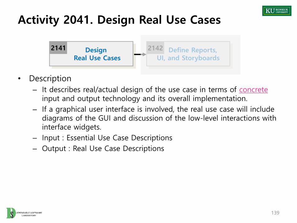
Activity 2041. Design Real Use Cases
• Description
– It describes real/actual design of the use case in terms of concreteinput and output technology and its overall implementation.
– If a graphical user interface is involved, the real use case will include diagrams of the GUI and discussion of the low-level interactions with interface widgets.
– Input : Essential Use Case Descriptions
– Output : Real Use Case Descriptions
139
Define Reports,UI, and Storyboards
2142DesignReal Use Cases
2141

Activity 2041. Design Real Use Cases
• Steps
1. Select each use case from essential use cases
2. Add user interface widgets into the expanded format, and concrete implementation details into the typical courses of events
140
Object Store
End Sale Make PaymentEnter Item
Price
Total
Tendered
Quantity
Descrpt.
Balance
UPC
B
C
D
E
F
G
H I J
A
Window-1
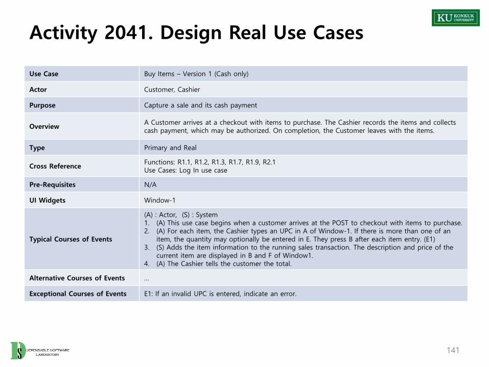
Activity 2041. Design Real Use Cases
141
Use Case Buy Items – Version 1 (Cash only)
Actor Customer, Cashier
Purpose Capture a sale and its cash payment
OverviewA Customer arrives at a checkout with items to purchase. The Cashier records the items and collects cash payment, which may be authorized. On completion, the Customer leaves with the items.
Type Primary and Real
Cross ReferenceFunctions: R1.1, R1.2, R1.3, R1.7, R1.9, R2.1Use Cases: Log In use case
Pre-Requisites N/A
UI Widgets Window-1
Typical Courses of Events
(A) : Actor, (S) : System1. (A) This use case begins when a customer arrives at the POST to checkout with items to purchase.2. (A) For each item, the Cashier types an UPC in A of Window-1. If there is more than one of an
item, the quantity may optionally be entered in E. They press B after each item entry. (E1)3. (S) Adds the item information to the running sales transaction. The description and price of the
current item are displayed in B and F of Window1.4. (A) The Cashier tells the customer the total.
Alternative Courses of Events …
Exceptional Courses of Events E1: If an invalid UPC is entered, indicate an error.

Activity 2042. Define Reports, UI, and Storyboards
• Description
– Design UI storyboard and UI components.
– Input : Requirements Specification, Real Use Case Descriptions
– Output : UI Storyboard, UI Component Design Specification
142
Define Reports,UI, and Storyboards
2142DesignReal Use Cases
2141 RefineSystem Architecture
2143 b

Activity 2043. Refine System Architecture
• Description
– Refine draft system architecture developed in the plan stage
– Input : Draft System Architecture
– Output : A package diagram, a deployment diagram
– Standards Applied
• UML’s Package Diagram
• UML’s Deployment Diagram
143
Define Reports,UI, and Storyboards
2142 RefineSystem Architecture
2143 bDefine
Interaction Diagrams
2144

Activity 2043. Refine System Architecture
• Steps (1~3: Deployment diagram , 4~7: Package diagram)
1. Define a 3-tier layered system architecture
• Presentation Layer : Windows, Reports, and so on
• Application Logic Layer : Tasks and rules that govern the process
• Storage Layer : Persistent storage mechanism
144
ApplicationLogic
Storage
Presentation
Record salesAuthorizepayments
POSTApplet
Database

Activity 2043. Refine System Architecture
2. Decompose the application logic tier into finer layers
• Domain object layer
– Classes representing domain concepts
• Service layer
– Service objects for functions such as database interaction, reporting, communications, security, and so on
145
ApplicationLogic
Storage
Presentation
Database
Sale
POSTApplet
DatabaseInterface ReportGenerator
Payment
“Services Layer”
“Domain Layer”

Activity 2043. Refine System Architecture
3. Assign each tier into different physical computing nodes, and/or different processes
146
ApplicationLogic
Storage
Presentation
Database
Sale
POSTApplet
DatabaseInterface ReportGenerator
Payment
Client computer
ApplicationServer
Data Server

Activity 2043. Refine System Architecture
4. Identify packages
• Place elements together
– that are in the same subject area-closely related by concept or purpose, or that are in a type hierarchy together
– that participate in the same use cases or
– that are strongly associated
147
Core
Products
POST Store Manager
Sales
SalesLineItem
Sale Cashier Customer
ItemProductCatalog
ProductSpecification

Activity 2043. Refine System Architecture
5. Layers of the architecture :
• vertical tiers
Partitions of the architecture :
• horizontal division of relatively parallel subsystems
148
Domain
Services
Core Elements Sales Products
Relational DatabaseInterface
Communication ReportingObject Database
Interface
Vertical
Layers
Horizontal Partitions

Activity 2043. Refine System Architecture
6. Determine package dependencies
• Dependency relationships indicates coupling between packages.
149
Domain
Core Elements Sales
Dependency

Activity 2043. Refine System Architecture
7. Assign visibility between package classes.
• Access into the Domain packages
– Some packages, typically the presentation package, have visibility into many of the classes representing domain concepts
• Access into the Service packages
– Some packages, typically the Domain and Presentation packages, have visibility into only one or a very few classes in each particular Service package
• Access into the Presentation packages
– No other packages have direct visibility to the Presentation layer
150

Activity 2043. Refine System Architecture
151
Domain
RDB Interface Security
Sale
...
...
Payment
...
...
Product Catalog
...
...
Broker
...
...
Proxy
...
...
SecurityFacade
User
...
...
Visibility into many classesfrom other packages.
Visibility into one or only a few classes in each
Service package.
Product Description
...
...
DBFacade
...
addUser(User)...
...
get(id) : Objectsave(Object)...

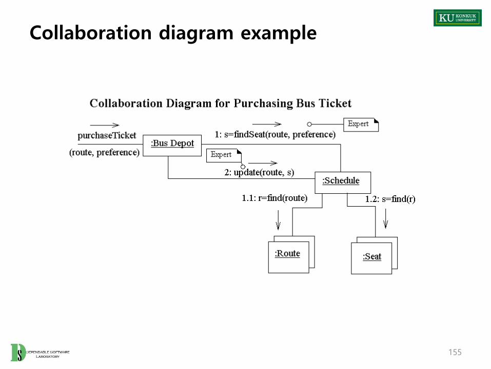
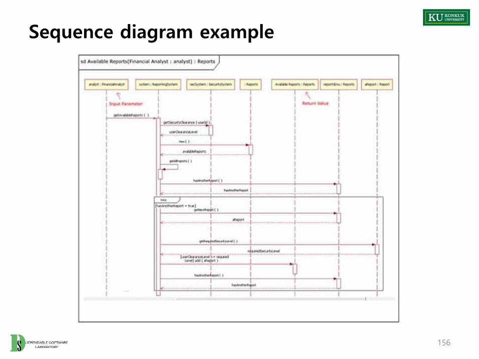
Activity 2044. Define Interaction Diagrams
• Description
– Collaboration diagrams illustrate object interactions in a graph or network format.
– To illustrate how objects interactions via messages to fulfill tasks.
– Input : Real Use Case Descriptions
– Output : An interaction diagram
– Standards Applied
• UML’s Sequence Diagram or Collaboration Diagram
152
RefineSystem Architecture
2143 bDefine
Interaction Diagrams
2144 Define Design Class Diagrams
2145 a

Activity 2044. Define Interaction Diagrams
• Interaction diagram is a generalization of two more specialized UML diagram types:
– Collaboration diagram
– Sequence diagram
• The both can be used to express similar message interactions
• Collaboration Diagram
– Illustrates object interactions in a graphs or network format
• Sequence Diagram
– Illustrates interactions in a kind of fence format, in which each new object is added to the right.
153

Activity 2044. Define Interaction Diagrams
• Sequence Diagram vs. Collaboration Diagram
Type Strengths Weaknesses
SequenceDiagram
Clearly shows sequence or time ordering of messages
Forced to extend to the right, when adding new objects with consuming horizontal space
CollaborationDiagram
Space economical and flexible to add new objects in two dimensions
Better to illustrate complex branching, iteration, and concurrent behavior
Difficult to see sequence of messages
154

Activity 2044. Define Interaction Diagrams
• Steps
1. Draw up actors
2. Deploy objects or classes participating each use case from the real use case descriptions and conceptual class diagram
3. Design a system of interacting objects to fulfill the tasks.
• Regard the use case description as a starting point
157

Activity 2044. Define Interaction Diagrams
• Illustrating Classes and Instances
:Sale
s1:Sale
Sale Class
Instance
Named Instance
158

Activity 2044. Define Interaction Diagrams
• Illustrating Links and Parameters
– A link is a connection path between two instances.
• Illustrating a Return Value
Msg1( )
1: addPayment(amount:Money)
:Sale:POST
Msg1( )
1: tot := total( ): Integer
:Sale:POST
159

Activity 2044. Define Interaction Diagrams
• Message Syntax
– return := message(parameter : parameterType) : returnType
– Standard UML message syntax
• Illustrating Messages to ‘Self’
(‘This’)
Msg1( )
1: addPayment(amount: Money)
:Sale:POST
Msg1( )
:POST
1: clear( )160

Activity 2044. Define Interaction Diagrams
• Illustrating Iterations
– Iteration
– Iteration Clause
Msg1( )
1*: li := nextLineItem( ): SalesLineItem
:Sale:POST
Msg1( )
1*: [i:=1..10] li := nextLineItem( ): SalesLineItem
:Sale:POST
161

Activity 2044. Define Interaction Diagrams
• Illustrating Creation of Instances– Creating message with optional initializing parameters”
• Illustrating Conditional Messages
Msg1( )
1: [new sale] create(cashier):Sale:POST
162

Activity 2044. Define Interaction Diagrams
• Illustrating Message Number Sequencing
– The first message is not numbered
– The order and nesting of subsequent messages are shown with a legal numbering scheme
:ClassB
msg1( )
:ClassA
:ClassC
1: msg2( )
1.1: msg3( )
163
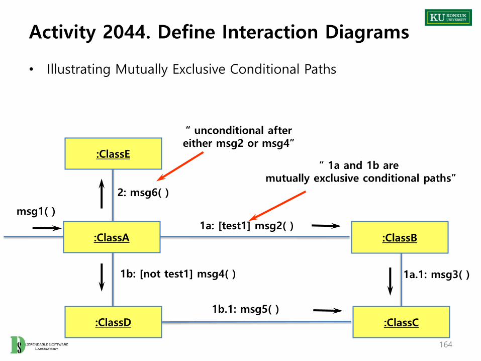
Activity 2044. Define Interaction Diagrams
• Illustrating Mutually Exclusive Conditional Paths
:ClassE
:ClassA
:ClassD
:ClassB
:ClassC
1b: [not test1] msg4( ) 1a.1: msg3( )
1b.1: msg5( )
1a: [test1] msg2( )
msg1( )
2: msg6( )
“ 1a and 1b are mutually exclusive conditional paths”
“ unconditional aftereither msg2 or msg4”
164

Activity 2044. Define Interaction Diagrams
• Illustrating Collections
– A multi-object, or set of instances, may be shown with a stack icon
sales:Sale
165

Activity 2044. Define Interaction Diagrams
• Illustrating Messages to Multi-objects
– A message to a multi-object icon indicates that it is sent to the collection object itself
:Sale
Msg1( )
:SalesLineItem
1: s :=size( ) : int
166

Activity 2044. Define Interaction Diagrams
• Illustrating Messages to a Class Object
– Messages may be sent to a class itself not an instance, in order to invoke class methods
:Sale
Msg1( )
Date
1: d1 := today( ): Date
167

Activity 2045. Define Design Class Diagrams
• Description– Describes more details in conceptual class diagram
– Add navigability, dependency, data type, operation signature, parameters, return types, and so on.
– Input : Interaction Diagram, Conceptual Class Diagram
– Output : A Design Class Diagram
– Standards Applied
• UML’s Class Diagram
168
DefineInteraction Diagrams
2144 Define Design Class Diagrams
2145 a DesignTraceability Analysis
2146

Activity 2045. Define Design Class Diagrams
• Steps
1. Identity all classes
2. Draw them in a class diagram
3. Add attributes
4. Add method names
5. Add type information to the attributes and methods
6. Add the associations
7. Add navigability arrows
8. Add dependency
169
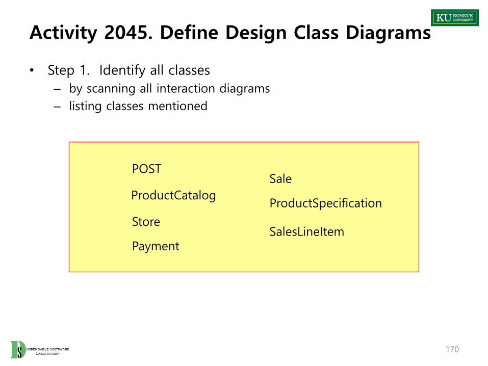
Activity 2045. Define Design Class Diagrams
• Step 1. Identify all classes
– by scanning all interaction diagrams
– listing classes mentioned
POSTSale
ProductCatalogProductSpecification
StoreSalesLineItem
Payment
170

Activity 2045. Define Design Class Diagrams
• Step 2. Draw a class diagram
– includes classes found in Step 1
ProductSpecification
SalesLineItem
Payment
SaleStore
ProductCatalogPOST
171

Activity 2045. Define Design Class Diagrams
• Step 3. Add attributes
– Include the attributes previously identified in the conceptual class diagram that are also used in the design
ProductSpecification
descriptionpriceUPC
SalesLineItem
quantity
Payment
amount
Sale
dateisCompletetime
Store
addressname
ProductCatalog
quantity
POST
172

Activity 2045. Define Design Class Diagrams
• Step 4. Add method names
– Identify method of each class by scanning the interaction diagrams
– The messages sent to a class in interaction diagrams must be defined in the class
– Don’t add
• creation methods and constructors
• accessing methods
• messages to a multiobject
Sale
makeLineitem()
dateisCompletetime
:Sale:POST
3: makeLineItem(spec, qty)
173

Activity 2045. Define Design Class Diagrams
ProductSpecification
descriptionpriceUPC
SalesLineItem
quantity
subtotal( )
Payment
amount
Sale
becomeComplete( )makeLineItem( )makePayment( )total( )
dateisCompletetime
Store
addressname
addSale( )
ProductCatalog
quantity
Specification( )
POST
endSale( )enterItem( )makePayment( )
174

Activity 2045. Define Design Class Diagrams
• Step 5. Add type information
– Show types of attributes, method parameters, and method return values optionally.
– Determine whether to show type information or not
• When using a CASE tool with automatic code generation, exhaustive details are necessary
• If it is being created for software developers to read, exhaustive detail may adversely effect the noise-to-value ratio
175

Activity 2045. Define Design Class Diagrams
ProductSpecification
description : Textprice : Quantityupc : UPC
SalesLineItem
quantity : integer
subtotal( ) : Quantity
Payment
amount : Quantity
Store
address : Addressname : Text
addSale(s:Sale)
ProductCatalog
specification(upc : integer) : ProductSpecification)
POST
endSale( )enerItem(upc : integer, qty : integer)makePayment(cash Tendered : Quantity)
Sale
becomeComplete( )makeLineItem(spec : ProdSpecification, qty : integer)makePayment(cashTendered : Quantity)total( ) : Quantity
date : DateisComplete : Booleantime : Time
Return type of method void : no return type
176Konkuk University

• Step 6. Add associations
– Choose associations by software-oriented need-to-know criterion from the interaction diagrams
• Step 7. Add navigability arrows
– According to the interaction diagram
– Common situations to define navigability
• A sends a message to B
• A creates an instance B
• A needs to maintain a connection to B
177Konkuk University
Activity 2045. Define Design Class Diagrams
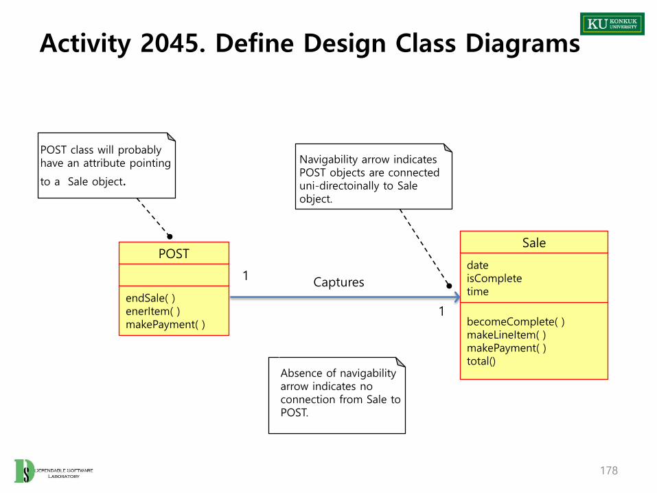
Activity 2045. Define Design Class Diagrams
POST
endSale( )enerItem( )makePayment( )
Sale
becomeComplete( )makeLineItem( )makePayment( )total()
date isComplete time
1
1
Captures
Absence of navigabilityarrow indicates noconnection from Sale toPOST.
Navigability arrow indicatesPOST objects are connecteduni-directoinally to Saleobject.
POST class will probablyhave an attribute pointing
to a Sale object.
178

Activity 2045. Define Design Class Diagrams
• Step 8. Add dependency relationship
– when there is non-attribute visibility between classes
– Non-attribute visibility : parameter, global, or locally declared visibility
179
ProductSpecification
description : Textprice : Quantityupc : UPC
SalesLineItem
quantity : integer
subtotal( )
Payment
amount : Quantity
Store
address : Addressname : Text
addSale( )ProductCatalog
specification( )
POST
endSale( )enerItem( )makePayment( )
Sale
becomeComplete( )makeLineItem( )makePayment( )total( )
date : DateisComplete : Booleantime : Time
Looks-in
Houses
CapturesContains
Contains
Logs-completed
Paid-by
Describes
1
1
1
11
1
1
1 1..*
1 1..*
1 1
*
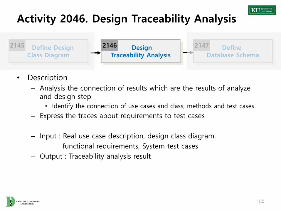
Activity 2046. Design Traceability Analysis
• Description
– Analysis the connection of results which are the results of analyze and design step
• Identify the connection of use cases and class, methods and test cases
– Express the traces about requirements to test cases
– Input : Real use case description, design class diagram,
functional requirements, System test cases
– Output : Traceability analysis result
180
Define DesignClass Diagram
2145 DesignTraceability Analysis
2146 Define Database Schema
2147

Activity 2046. Design Traceability Analysis
• Steps:
1. Identify the related information of essential and real use cases
• 1:1 or more
2. Identify the traces between operation contracts(2036) and operations in interaction diagram(2044)
• Express the direct contacts or hidden contacts
3. Identify the relations of the results of step 2 and class diagram (class, method)
4. Writing the results of the analysis
5. If the operations which are not expressed directly in this step (e.g. GUI related operation like text input), they should be written by 2053
181

Activity 2046. Design Traceability Analysis
• Draw up the traces between operation contracts(2036) and operations in interaction diagram(2044)
– Direct : Operation which is connected directly
– Hidden : Operations which are used to operate the function invisibly
182
HiddenDirect

Activity 2046. Design Traceability Analysis
• The results of step 3 and 4
183

Activity 2047. Define Database Schema
• Description– Design database, table, and records
– Map classes into tables
– Input : Design Class Diagram
– Output : A Database Schema
• Steps:1. Map classes into tables
2. Map relationships between classes into relations between tables
3. Map attributes into fields of tables
4. Design Schema
185
DesignTraceability Analysis
2146 Define Database Schema
2147

Phase 2040. Design
-Case Study-
Revise Plan
2110 Sync.Artifacts
2120
Analyze
2130
Design
2140
Construct
2150
Test
2160

Activity 2041. Design Real Use Cases
187
Use Case Login
Actor User, Manager
Purpose User와 manager가 시스템에 접속하기 위해 로그인 할 수 잇도록 한다.
OverviewID/PW 를 입력 받아 계정과 비밀번호가 일치하는 경우 user or manager로로그인 한다.일치하는 계정이 없는 경우 로그인 되지 않는다.
Type Primary
Cross Reference Functions: R 1.1,
Pre-Requisites N/A
Typical Courses of Events
(A) : Actor, (S) : System1. (A) : 화면에 ID, PW 를 입력 한다.2. (A) : 로그인 버튼을 누른다.3. (S) : Account의 User instance들의 id, pw와 비교 한다.4. (S) : 일치하는 instance가 존재하는 경우 user로 로그인 한다.5. (S) : Account의 Manager instance들의 id, pw와 비교 한다.6. (S) : 일치하는 instance가 존재하는 경우 manager 로 로그인 한다.7. (S) : 현재 로그인된 계정을 기록 한다.
Alternative Courses of Events
…
Exceptional Courses of Events
E1. 일치하는 계정이 없는 경우 접속되지 않는다.

Activity 2041. Design Real Use Cases
188
Use Case Logout
Actor User, Manager
Purpose 접속된 User or Manager의 접속을 종료한다.
OverviewLogout 버튼을 누르면 접속된 user or manager의 접속을 종료하고 초기화면으로 돌아간다.
Type Primary
Cross Reference Functions: R 1.1
Pre-Requisites Login이 선행 되어야 한다.
Typical Courses of Events
(A) : Actor, (S) : System1. (A) : 로그아웃 버튼을 누른다.2. (S) : ManagementSystem의 현재 로그인 정보를 초기화 한다.3. (S) : 초기화면으로 돌아간다.
Alternative Courses of Events
…
Exceptional Courses of Events
N/A
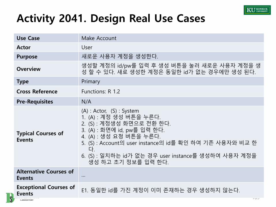
Activity 2041. Design Real Use Cases
189
Use Case Make Account
Actor User
Purpose 새로운 사용자 계정을 생성한다.
Overview생성할 계정의 id/pw를 입력 후 생성 버튼을 눌러 새로운 사용자 계정을 생성 할 수 있다. 새로 생성한 계정은 동일한 id가 없는 경우에만 생성 된다.
Type Primary
Cross Reference Functions: R 1.2
Pre-Requisites N/A
Typical Courses of Events
(A) : Actor, (S) : System1. (A) : 계정 생성 버튼을 누른다.2. (S) : 계정생성 화면으로 전환 한다.3. (A) : 화면에 id, pw를 입력 한다.4. (A) : 생성 요청 버튼을 누른다.5. (S) : Account의 user instance의 id를 확인 하여 기존 사용자와 비교 한
다.6. (S) : 일치하는 id가 없는 경우 user instance를 생성하여 사용자 계정을
생성 하고 초기 정보를 입력 한다.
Alternative Courses of Events
…
Exceptional Courses of Events
E1. 동일한 id를 가진 계정이 이미 존재하는 경우 생성하지 않는다.

Activity 2041. Design Real Use Cases
190
Use Case Identify Balance
Actor User
Purpose 사용자 계정에 남아있는 잔액을 확인 한다.
Overview 사용자의 잔액 확인 요청 시 남아있는 잔액을 확인하여 출력 한다.
Type Primary
Cross Reference Functions: R 1.3
Pre-Requisites 사용자로 login이 선행 되어야 한다.
Typical Courses of Events
(A) : Actor, (S) : System1. (A) : 잔액 확인 버튼을 누른다. 2. (S) : 현재 로그인된 user instance에서 balance값을 출력 한다.
Alternative Courses of Events
…
Exceptional Courses of Events
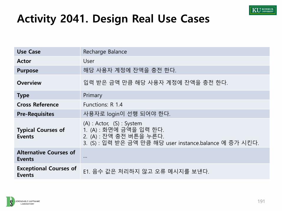
Activity 2041. Design Real Use Cases
191
Use Case Recharge Balance
Actor User
Purpose 해당 사용자 계정에 잔액을 충전 한다.
Overview 입력 받은 금액 만큼 해당 사용자 계정에 잔액을 충전 한다.
Type Primary
Cross Reference Functions: R 1.4
Pre-Requisites 사용자로 login이 선행 되어야 한다.
Typical Courses of Events
(A) : Actor, (S) : System1. (A) : 화면에 금액을 입력 한다.2. (A) : 잔액 충전 버튼을 누른다.3. (S) : 입력 받은 금액 만큼 해당 user instance.balance 에 증가 시킨다.
Alternative Courses of Events
…
Exceptional Courses of Events
E1. 음수 값은 처리하지 않고 오류 메시지를 보낸다.

Activity 2041. Design Real Use Cases
192
Use Case Request Print
Actor User
Purpose 사용자의 요청을 받아 인쇄를 진행 한다.
Overview 사용자의 요청을 받아 입력된 매수 만큼 인쇄를 진행 한다.
Type Primary
Cross Reference Functions: R 2.1, R 2.2
Pre-Requisites 사용자로 login이 선행 되어야 한다.
Typical Courses of Events
(A) : Actor, (S) : System1. (A) : 화면에 필요 인쇄 매수를 입력 한다.2. (A) : 인쇄 버튼을 누른다.3. (S) : ManagementSystem에서 매수에 따라 요금을 계산 한다.4. (S) : check balance use case를 통해 잔액을 비교 한다.5. (S) : 잔액이 부족하면 ERROR 메시지 후 종료 한다.6. (S) : 인쇄 매수와 printer의 paper를 비교하여 부족할 경우 종료 한다.7. (S) : printer 의 paper를 매수 만큼 감소 시킨다.8. (S) : allProfit 을 요금 만큼 증가 시킨다.9. (S) : user instance.balance를 요금만큼 감소 시킨다.
Alternative Courses of Events
…
Exceptional Courses of Events
E 2. 매수가 음수일 경우 진행하지 않는다.

Activity 2041. Design Real Use Cases
193
Use Case Check Balance
Actor Event-based
Purpose 인쇄 진행 시 잔액과 필요 요금을 확인 및 비교 한다.
Overview사용자의 요청에 의해 인쇄 진행 시 시스템의 요청을 받아 필요 요금과 잔액을 체크한다.
Type Primary
Cross ReferenceFunctions: R 2.1, R 2.2Use Cases: Request Print
Pre-Requisites 시스템에 인쇄 요청 후에 동작 한다.
Typical Courses of Events
(A) : Actor, (S) : System1. (S - A) : 사용자의 인쇄 요청을 받은 시스템이 잔액 확인을 요청한다.2. (S) : user instance 의 balance와 필요 요금을 비교한 결과를 보낸다.
Alternative Courses of Events
…
Exceptional Courses of Events

Activity 2041. Design Real Use Cases
194
Use Case Identify Paper
Actor Manager
Purpose 시스템 관리자가 프린터에 남은 용지를 확인 할 수 있다.
Overview 시스템 관리자의 요청에 따라 프린터에 남은 용지 잔량을 확인한다.
Type Primary
Cross Reference Functions: R 3.1
Pre-Requisites Manager로 로그인 되어 있어야 한다.
Typical Courses of Events
(A) : Actor, (S) : System1. (A) : 용지 확인 버튼을 누른다.2. (S) : printer 의 paper 값을 출력 한다.
Alternative Courses of Events
…
Exceptional Courses of Events
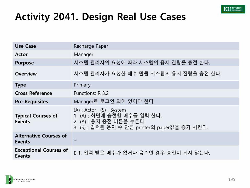
Activity 2041. Design Real Use Cases
195
Use Case Recharge Paper
Actor Manager
Purpose 시스템 관리자의 요청에 따라 시스템의 용지 잔량을 충전 한다.
Overview 시스템 관리자가 요청한 매수 만큼 시스템의 용지 잔량을 충전 한다.
Type Primary
Cross Reference Functions: R 3.2
Pre-Requisites Manager로 로그인 되어 있어야 한다.
Typical Courses of Events
(A) : Actor, (S) : System1. (A) : 화면에 충전할 매수를 입력 한다.2. (A) : 용지 충전 버튼을 누른다.3. (S) : 입력된 용지 수 만큼 printer의 paper값을 증가 시킨다.
Alternative Courses of Events
…
Exceptional Courses of Events
E 1. 입력 받은 매수가 없거나 음수인 경우 충전이 되지 않는다.

Activity 2041. Design Real Use Cases
196
Use Case Identify User
Actor Manager
Purpose 관리자가 사용자들의 정보를 확인 한다.
Overview 관리자의 요청에 따라 사용자들의 id/pw, 잔액 정보를 확인한다.
Type Primary
Cross Reference Functions: R 3.3
Pre-Requisites Manager로 로그인 되어 있어야 한다.
Typical Courses of Events
(A) : Actor, (S) : System1. (A) : 사용자 확인 버튼을 누른다. 2. (S) : Account 의 모든 user instance 정보를 출력 한다.
Alternative Courses of Events
…
Exceptional Courses of Events
E1. user instance 에 아무 정보가 없는 경우 출력하지 않는다.

Activity 2041. Design Real Use Cases
197
Use Case Identify Money
Actor Manager
Purpose 총 수익을 확인 한다.
Overview 관리자의 요청에 따라 지금까지의 총 수익을 확인 한다.
Type Primary
Cross Reference Functions: R 3.4
Pre-Requisites Manager로 로그인 되어 있어야 한다.
Typical Courses of Events
(A) : Actor, (S) : System1. (A) : 수익 확인 버튼을 누른다.2. (S) : allProfit 값을 출력 한다.
Alternative Courses of Events
…
Exceptional Courses of Events

Activity 2044. Define Interaction Diagrams
• Sequence diagram으로 작성
– Identify User use case example
201

Activity 2046. Design Traceability Analysis
• Tracing operations in interaction diagram with class diagram
204

Activity 2046. Design Traceability Analysis
• Tracing operations in interaction diagram with class diagram
205

Phase 2050. Construct
Revise Plan
2110 Sync.Artifacts
2120
Analyze
2130
Design
2140
Construct
2150
Test
2160

Phase 2050. Construct
• Phase 2050 Activities
207
ImplementWindows
2152
Write UnitTest Code
2155
Implement Class& Methods Definitions
2151 ImplementReports
2153
Construct2150
ImplementDB Schema(SQL, etc.)
2154

Activity 2051. Implement Class & Methods Definitions
• Description
– Implement class & methods in accordance with design class diagram
– Describes the description of class and methods
• It is used to design unit test cases
– Input : Design class diagram, real use cases, Interaction diagram
– Output : Class & Methods description
• Steps:1. Identify all classes and methods in design class diagram(2045)
2. Writing description of the target by using below format
3. Implement
208
Implement Class& Methods Definitions
2151

Activity 2051. Implement Class & Methods Definitions
209
Type Class or Method
Name The name of class o method
Purpose Writing the purpose of class or method
Overview (Class) Information of class or method
Cross ReferenceFunctions: Writing related system functions Use Cases : Writing related use cases
Input (Method) Writing all of inputs of methods
Output (Method) Writing the output of methods
Abstract operation (Method) Writing operation information of methods briefly
Exceptional Courses of Events Writing exception state and handling information

Activity 2052. Implements Windows
• Description
– Define relations between GUI and operation
• Implements GUI class between actor and system
– Input : Interaction diagram, design class diagram, real use case description, UI Story board, operation contracts
– Output : GUI implements results and description, Refined Class Diagram
• Steps:1. Define GUI system operation between Actor and System in interaction
diagram
2. Draw the refined interaction diagram by adding GUI operation
3. Draw up the description (using below format) of GUI operation in diagram
210
ImplementWindows
2152

Activity 2052. Implements Windows
211
Name A name of operation
Resposibilities Writing the paper number to text box
Type GUI
Cross References R 2.1
Notes Shows the value of text box in screen
Pre-Conditions User should be logged in before
Post-Conditions Paper text box shows the input value

Activity 2052. Implements Windows
• An example of operations in Request Print use case
212
enterSheet (text input with only GUI) Text Input
reqPrint Connection with printButton
showPrint Print message Connection with showPrint
User와 System 사이에 GUI가 추가됨
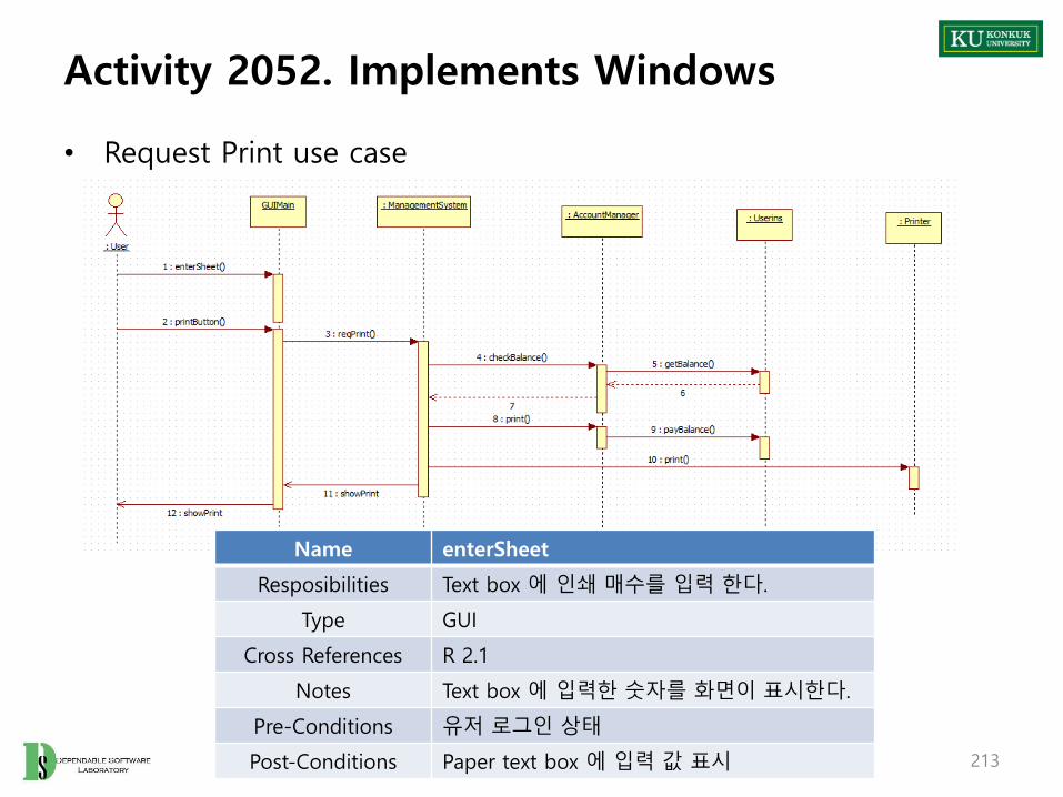
Activity 2052. Implements Windows
• Request Print use case
213
Name enterSheet
Resposibilities Text box 에 인쇄 매수를 입력 한다.
Type GUI
Cross References R 2.1
Notes Text box 에 입력한 숫자를 화면이 표시한다.
Pre-Conditions 유저 로그인 상태
Post-Conditions Paper text box 에 입력 값 표시

Activity 2053. Implement Reports
• Description
– Reports which have information of analysis, design results is refined and implemented in this process again
– Input : All of information
– Output : Analysis, design reports
214
ImplementReports
2153
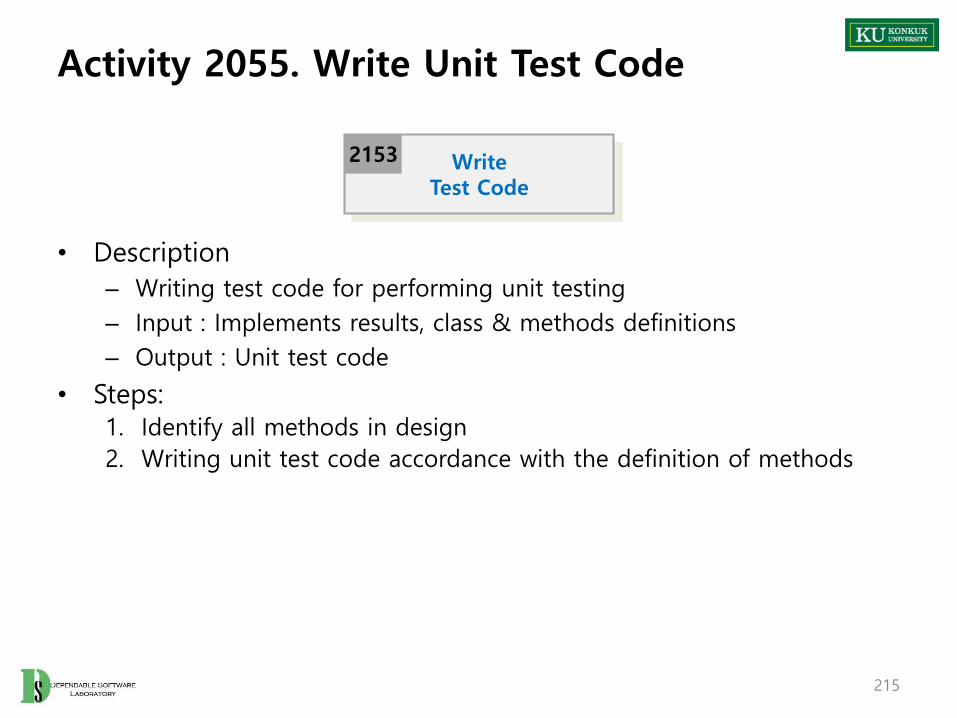
Activity 2055. Write Unit Test Code
• Description
– Writing test code for performing unit testing
– Input : Implements results, class & methods definitions
– Output : Unit test code
• Steps:1. Identify all methods in design
2. Writing unit test code accordance with the definition of methods
215
WriteTest Code
2153

Phase 2050. Construct
-Case Study-
Revise Plan
2110 Sync.Artifacts
2120
Analyze
2130
Design
2140
Construct
2150
Test
2160

Activity 2051. Implement Class & Methods Definitions
• Class definitions
217
Type Class
Name ManagementSystem
PurposeGUI 를 포함한 메인 클래스로써 ACTOR 와의연결 관계를 가지며 다른 기능 들을 지원하기위한 class
Overview
Cross ReferenceFunctions: AllUse Cases : All
Exceptional Courses of Events

Activity 2051. Implement Class & Methods Definitions
218
Type Class
Name AccountManager
PurposeUser, manager 계정 관리와 관련 기능에 대한class
Overview
Cross ReferenceFunctions: R 1.2, R 1.3, R 1.4, R 2.1, R 2.2Use Cases :
Exceptional Courses of Events
Type Class
Name User
Purpose User 계정 정보 저장을 위한 class
Overview
Cross ReferenceFunctions: R 1.1, R 1.2, R1.3, R 1.4, R 2.1, R 2.2, R 3.3Use Cases :
Exceptional Courses of Events

Activity 2051. Implement Class & Methods Definitions
219
Type Class
Name Manager
Purpose Manager 계정 정보 저장을 위한 class
Overview
Cross ReferenceFunctions: R 1.1Use Cases :
Exceptional Courses of Events
Type Class
Name Printer
Purpose인쇄 시스템의 프린터 정보 관리 및 기능 관리를 위한 class
Overview
Cross ReferenceFunctions: R 3.1, R 3.2, R 3.4Use Cases :
Exceptional Courses of Events

Activity 2051. Implement Class & Methods Definitions
• Method definitions
220
Type Method
Name reqLogin in ManagementSystem class
PurposeUser, manager 의 login 요청을 처리하기 위한method
Cross ReferenceFunctions: R 1.1Use Cases : 1. Login
Input (Method) id: String, pw: String
Output (Method) N/A
Abstract operation (Method)
1. 유저가 입력한 id, pw와 함께 로그인 요청을받아 accountManager class의 checkLogin함수를 호출 한다.
Exceptional Courses of Events
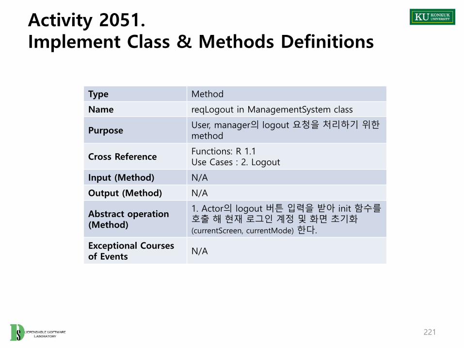
Activity 2051. Implement Class & Methods Definitions
221
Type Method
Name reqLogout in ManagementSystem class
PurposeUser, manager의 logout 요청을 처리하기 위한method
Cross ReferenceFunctions: R 1.1Use Cases : 2. Logout
Input (Method) N/A
Output (Method) N/A
Abstract operation (Method)
1. Actor의 logout 버튼 입력을 받아 init 함수를호출 해 현재 로그인 계정 및 화면 초기화(currentScreen, currentMode) 한다.
Exceptional Courses of Events
N/A

Activity 2051. Implement Class & Methods Definitions
222
Type Method
Name rechargeMoney in User class
Purpose User 계정 instance에 잔액 충전
Cross ReferenceFunctions: R 1.4Use Cases : recharbe balance
Input (Method) Money:int
Output (Method) N/A
Abstract operation (Method)
1. 현재 instance의 balance값을 input 으로 들어온 money 만큼 증가 시킨다.
Exceptional Courses of Events
N/A

Activity 2051. Implement Class & Methods Definitions
223
Type Method
Name reqPrint in ManagementSystem class
Purpose User 의 인쇄 요청을 처리하기 위한 method
Cross ReferenceFunctions: R 2.1, 2.2Use Cases : Request Print
Input (Method) paper:int
Output (Method) N/A
Abstract operation (Method)
1. AccountManager의 checkBalance 메소드를 호출 한다.
2. checkBalance 메소드 실행 결과가 인쇄 가능일 경우 AccountManager의 print 메소드와, Printer의 print 메소드를 호출 하며각각 paper를 인자로 전달 한다.
3. 인쇄 불가능의 경우 에러 메시지를 전달 한다.
Exceptional Courses of Events
N/A

Activity 2051. Implement Class & Methods Definitions
224
Type Method
Name makeAccount in AccountManager class
PurposeUser, manager 계정에 같은 id가 존재하는지check 하는 메소드
Cross ReferenceFunctions: R 1.2Use Cases : 3. Make Account
Input (Method) id: String, pw: String
Output (Method) Boolean
Abstract operation (Method)
1. userList 탐색을 통해 각 user instance 별로check 메소드를 호출 한다.
2. Manager instance의 check 메소드를 호출한다.
3. 각 instance의 check 메소드 호출 결과가모두 존재하지 않는 경우 새로운 user instance를 생성 후 userList에 삽입 한다.
4. 생성한 새 user instance의 id, pw를 설정하고 balance 초기화 후 true를 리턴 한다.
5. 같은 id를 가진 계정이 존재하는 경우 false를 리턴 한다.
Exceptional Courses of Events
N/A

Activity 2052. Implements Windows
• An example of operations in Request Print use case
225

Activity 2052. Implements Windows
• An example of operations in Request Print use case
226
enterSheet GUI 만 존재 (text 입력) Text 입력
reqPrint printButton 과 연결
showPrint Print message showPrint 와 연결

Activity 2052. Implements Windows
227
Name enterSheet
Resposibilities Text box 에 인쇄 매수를 입력 한다.
Type GUI
Cross References R 2.1
Notes Text box 에 입력한 숫자를 화면이 표시한다.
Pre-Conditions 유저 로그인 상태
Post-Conditions Paper text box 에 입력 값 표시
Name printButton
Resposibilities Print button 을 누른다.
Type GUI
Cross References R 2.2
NotesPrint button을 눌러 reqPrint 메소드를 호출하고, text의 값을 전달 한다.
Pre-Conditions유저 로그인 상태, paper text box 에 입력 값 존재
Post-ConditionsSystemManagement class의 reqPrint 메소드를호출하여 print를 진행 한다.

Activity 2053. Implement Reports
• Report 작성
– 1000 result
– 2030 result
– 2040 result
– 2050 result
• 본 예제는 현재 ppt에 포함
228

Activity 2055. Write Unit Test Code
• 앞의 method description을 이용하여 unit test code 작성
– Method description의 input, output, abstract operation 등 이용
229
Phase 2060. Test
Revise Plan
2110 Sync.Artifacts
2120
Analyze
2130
Design
2140
Construct
2150
Test
2160

Phase 2060. Test
• Phase 2060 Activities
231
IntegrationTesting
2162System Testing
2163
DocumentationTesting
2166
Unit Testing2161
PerformanceTesting
2164
Test2160
AcceptanceTesting
2165
TestingTraceability Analysis
2167
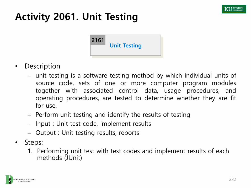
Activity 2061. Unit Testing
• Description
– unit testing is a software testing method by which individual units ofsource code, sets of one or more computer program modulestogether with associated control data, usage procedures, andoperating procedures, are tested to determine whether they are fitfor use.
– Perform unit testing and identify the results of testing
– Input : Unit test code, implement results
– Output : Unit testing results, reports
• Steps:1. Performing unit test with test codes and implement results of each
methods (JUnit)
232
Unit Testing2161

Activity 2062. Integration Testing
• Description
– Integration testing is the phase in software testing in which individual software modules are combined and tested as a group
– Input : Class & Method definitions
– Output : Integration testing results, reports
234
IntegrationTesting
2162

Activity 2063. System Testing
• Description
– System testing of software or hardware is testing conducted on a complete, integrated system to evaluate the system's compliance with its specified requirements.
– Input : Implements results, system test plan and cases
– Output : System testing results, reports
• Steps:1. Identify system test cases before defined
2. Set the test data of test cases for testing
3. Performing system testing with system test plan and cases (JFeature)
235
System Testing2163

Activity 2063. System Testing
• Set the test data of test cases for testing
– Example of test case 1-1 & 1-2
– 1-1 : id 입력란에 test, pw 입력란에 test 입력 후 login 버튼을 누른다.
– 1-2 : id 입력란에 test2, pw 입력란에 asdf 입력 후 login 버튼을 누른다.
236
1 – 1 로그인 시험존재하는 계정의 Id, pw를 입력하고 로그인시도를 하여 로그인 기능 test
1. Login R 1.1
1 - 2 로그인 시험존재하지 않는 계정의 Id, pw를 입력하고 로그인 시도를 하여 로그인 기능 test
1. Login R 1.1

Activity 2064. Performance Testing
• Description
– Performance testing is in general, a testing practice performed to determine how a system performs in terms of responsiveness and stability under a particular workload.
– Input : Implements result (program)
– Output : Performance testing results, reports
237
PerformanceTesting
2164

Activity 2065. Acceptance Testing
• Description
– Acceptance testing is a test conducted to determine if the requirements of a specification or contract are met
– It is used to determine the final acceptance
– Input : Requirements specification, system
– Output : Acceptance testing results, reports
238
AcceptanceTesting
2165

Activity 2066. Documentation Testing
• Description
– Documentation testing is a type of non-functional testing
– It intends to check the quality of documentation
– Input : All documents in process
– Output : Documentation testing results, reports
239
DocumentationTesting
2166

Activity 2066. Testing Traceability Analysis
• Description
– Identify the relations between design and test cases
– Input : Testing results, traceability documents
– Output : Testing – design traceability reports
• Step
1. Identify system test cases and unit test cases
2. Identify the relations between requirements and system test cases
• System test cases should be covered all requirement specification
3. Identify the relations between methods (component) and unit test cases
240
TestingTraceability Analysis
2167

Phase 2060. Test
-Case Study-
Revise Plan
2110 Sync.Artifacts
2120
Analyze
2130
Design
2140
Construct
2150
Test
2160

Activity 2061. Unit Testing
• 2055에서 작성한 unit test code를 이용하여 testing후 report 작성
243

Activity 2063. System Testing
• Identify system test cases before defined
244
Test Number
Test 항목 DescriptionUseCase
System Function
1 – 1 로그인 시험존재하는 계정의 Id, pw를 입력하고 로그인 시도를 하여 로그인 기능 test
1. Login R 1.1
1 - 2 로그인 시험존재하지 않는 계정의 Id, pw를 입력하고 로그인 시도를 하여 로그인 기능 test
1. Login R 1.1
2 로그아웃 시험로그인 상태에서 로그아웃 버튼을 눌러 로그아웃 기능 test
2. Logout R 1.1
3 계정 생성 시험계정 생성 데이터를 입력하여 계정 생성 기능test
3. Make Account R 1.2
4 잔액 확인 시험 잔액 확인 버튼 동작 여부 test 4. Identify Balance R 1.3
5 잔액 충전 시험 금액을 입력하고 잔액 충전 기능 test5. Recharge Balance
R 1.4
6 인쇄 버튼 시험 인쇄 매수를 입력하고 인쇄 기능 test 6. Request Print R 2.1
7 – 1 잔액 체크 시험잔액이 충분한 상태에서 인쇄 매수를 입력하고 인쇄 기능 test 수행
7. Check Balance R 2.2
7 – 2 잔액 체크 시험잔액이 부족한 상태에서 인쇄 매수를 입력하고 인쇄 기능 test 수행
7. Check Balance R 2.2
8 용지 확인 시험 용지 잔량 출력 버튼을 통해 기능 test 8 Identify Paper R 3.1
9 용지 충전 시험 충전할 용지 수량을 입력하고 용지 충전 test 9. Recharge Paper R 3.2
10 사용자 목록 확인 시험 전체 사용자 목록 출력 test 10. Identify User R 3.3
11 수익 확인 시험 총 수익 출력 test 11. Identify Money R 3.4

Activity 2063. System Testing
• Set the test data of test cases for testing
– Example of test case 1-1 & 1-2
– 1-1 : id 입력란에 test, pw 입력란에 test 입력 후 login 버튼을 누른다.
– 1-2 : id 입력란에 test2, pw 입력란에 asdf 입력 후 login 버튼을 누른다.
245
1 – 1 로그인 시험존재하는 계정의 Id, pw를 입력하고 로그인시도를 하여 로그인 기능 test
1. Login R 1.1
1 - 2 로그인 시험존재하지 않는 계정의 Id, pw를 입력하고 로그인 시도를 하여 로그인 기능 test
1. Login R 1.1