29
Software Narrative: Brawns AND Brains TEAM 12 - SUPER TANK
| Date post: | 03-Jan-2016 |
| Category: |
Documents |
| Upload: | francis-king |
| View: | 219 times |
| Download: | 0 times |

Software Narrative: Brawns AND Brains
TEAM 12 - SUPER TANK

OVERVIEW
Project Refresher
Software Architecture Overview
The High Level – LRVC Protocol
The Low Level – Main Embedded System
Summary

PROJECT REFRESHER
Long Range Vehicle (Tank) Control over wireless network
Operate from anywhere in the world (Website/Android App)
Collaboration with HKUST
Shared Server
Customizable for new vehicle features
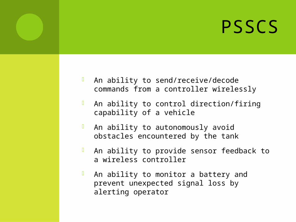
PSSCS
An ability to send/receive/decode commands from a controller wirelessly
An ability to control direction/firing capability of a vehicle
An ability to autonomously avoid obstacles encountered by the tank
An ability to provide sensor feedback to a wireless controller
An ability to monitor a battery and prevent unexpected signal loss by alerting operator
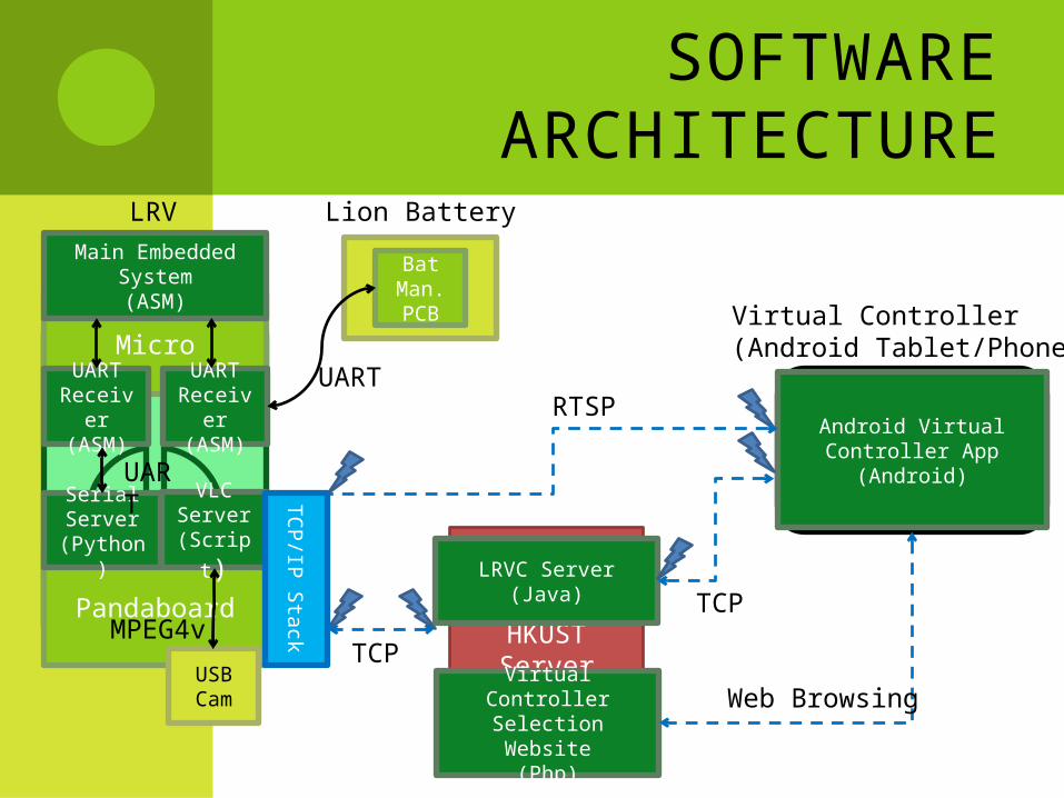
SOFTWARE ARCHITECTURE
HKUST Server
LRVVirtual Controller(Android Tablet/Phone)
Pandaboard
Micro
VLC Server(Script)
Serial Server
(Python)
Android Virtual Controller App (Android)
TCP/IP Stack
UARTReceiver
(ASM)
Main Embedded System(ASM)
LRV
LRVC Server(Java)
RTSP
TCP
UART
UARTReceiver
(ASM)
USB Cam
Bat Man. PCB
MPEG4v
Lion Battery
UART
TCP
Virtual Controller Selection Website
(Php)
Web Browsing

THE HIGH LEVEL – LRVC PROTOCOL OVERVIEW
The LRVC Protocol provides a framework for communications between a Virtual Controller and an LRV. The LRVC Protocol has been designed to be flexible enough to accommodate a diverse set of functionalities in an LRV yet structured enough to yield a fair amount of code re-use between LRV implementations.

THE HIGH LEVEL – LRVC PROTOCOL PROPERTIES
Android Compatible
Extendable
Robust UI Support
Video Streaming
Multiple Users
Secure

THE HIGH LEVEL – LRVC PROTOCOL

THE HIGH LEVEL – LRVC PROTOCOL
HKUST Server
LRVVirtual Controller(Android Tablet/Phone)
Pandaboard
Micro
VLC Server(Script)
Serial Server
(Python)
Android Virtual Controller App (Android)
TCP/IP Stack
UARTReceiver
(ASM)
Main Embedded System(ASM)
LRV
LRVC Server(Java)
UARTReceiver
(ASM)
USB Cam
Bat Man. PCB
Lion Battery
Virtual Controller Selection Website
(Php)THE LRVC Protocol
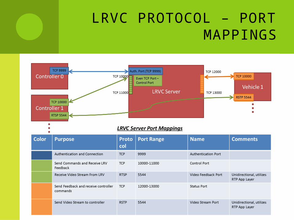
LRVC PROTOCOL – PORT MAPPINGS

LRVC PROTOCOL - THE PHASES
Connection Phase - This phase is responsible for the security and resource allocation of the LRVC Server along with providing services for the Virtual Controller to provide a User with a selection screen of LRV options.
Configuration Phase - This phase is responsible for the configuration of a Virtual Controller. It populates the Virtual Controller with a standard interface of Standard Objects and a unique set of custom objects called Non-Standard Objects. These objects all have a known interface.
Control Phase - This phase is responsible for synchronously distributing opcodes (aka commands) to an LRV at the rate of 10Hz. Additionally, it wraps and transports the LRV’s feedback as Status Messages back to the Virtual Controller at a rate of 10Hz. Lastly, it facilitates a video feed from the LRV back to the Virtual Controller at a target rate of 20Hz.

LRVC PROTOCOL - CONFIGURATION
HKUST Server
LRVVirtual Controller(Android Tablet/Phone)
Pandaboard
Micro
VLC Server(Script)
Serial Server
(Python)
Android Virtual Controller App (Android)
TCP/IP Stack
UARTReceiver
(ASM)
Main Embedded System(ASM)
LRV
LRVC Server(Java)
UARTReceiver
(ASM)
USB Cam
Bat Man. PCB
Lion Battery
Virtual Controller Selection Website
(Php)
Web Browsing
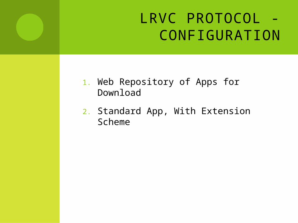
LRVC PROTOCOL - CONFIGURATION
1. Web Repository of Apps for Download
2. Standard App, With Extension Scheme

LRVC PROTOCOL – WEB REPOSITORY
Web Browse To This WebpageLRV #1
LRV #1 Description
Download
LRV #2
LRV #2 Description
Download
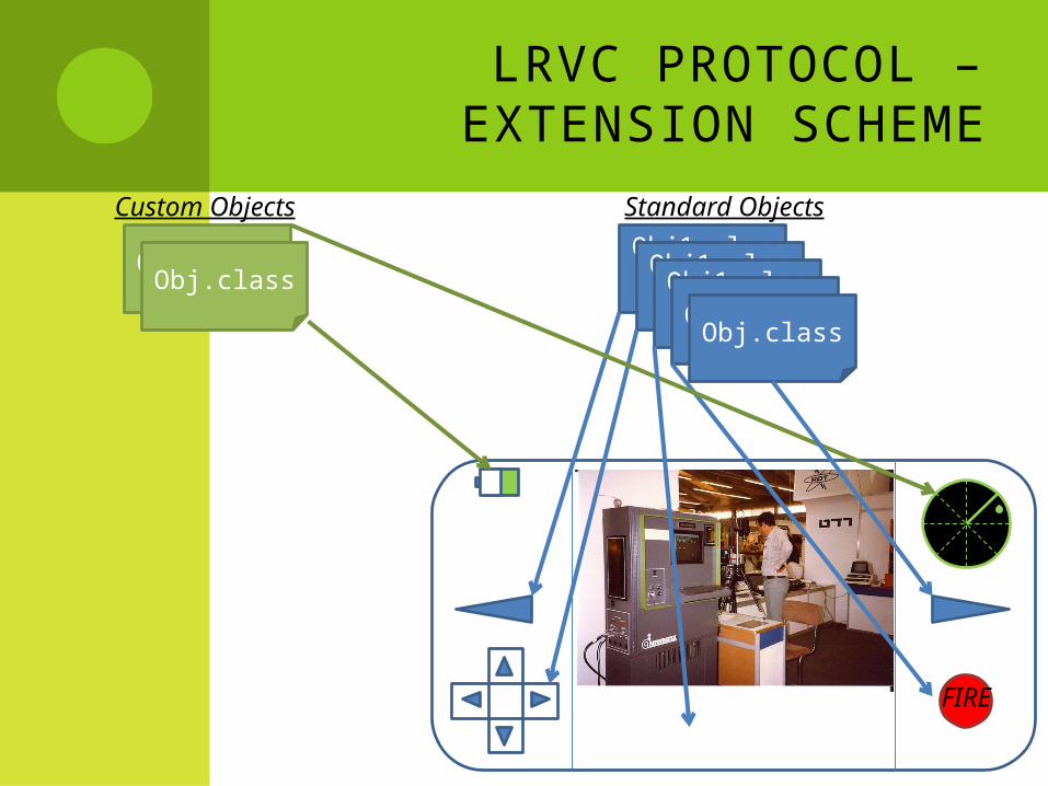
LRVC PROTOCOL – EXTENSION SCHEME
FIRE
Obj1.classObj1.class
Obj1.classObj.class
Obj.classObj.class
Standard ObjectsCustom Objects
Obj.class

CONTROLLER OBJECTS
Obj.class
CustomLRVCObject Interface
getOpcode()
public boolean wasActivated()Used internally to aggregate activated objects
giveResponse()
“Speed 8mph” 0xA3

CONTROLLER OBJECTS
FIRE
0x11
0x07
0x06 0x0A 0x10 0x0C 0x01
NOTE: Opcodes are made up
Command Msg

CONTROLLER OBJECTS
FIRE
NOTE: Responses are made up
Status Msg
(3ft, 2ft)
“No Events”
0x2F
Video Stream

THE BIG PICTURE
The basic idea is that the protocol allows extension and custom implementation through creating custom GUI objects (Java objects that contain a known “CustomLRVCObjects” interface), serializing them through the standard Java library, and interfacing them through the controllers GUI. Thus, the custom implementation is achieved not by modifying the LRVC Protocol but by adjusting the bindings of these GUI components.
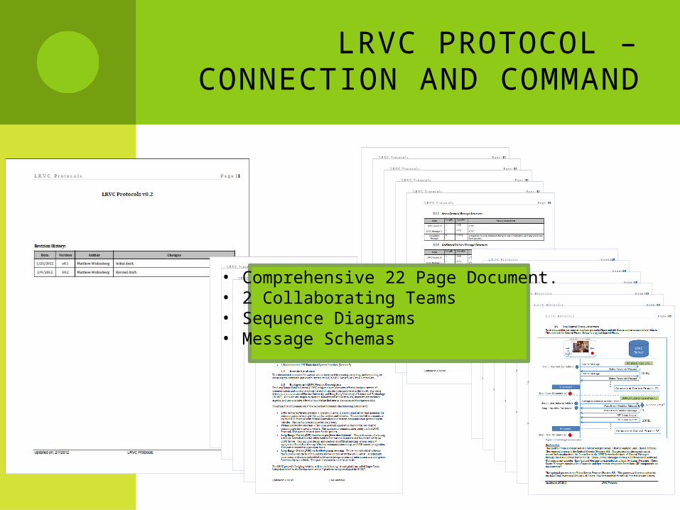
LRVC PROTOCOL – CONNECTION AND COMMAND
• Comprehensive 22 Page Document.• 2 Collaborating Teams• Sequence Diagrams• Message Schemas
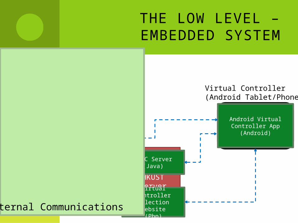
THE LOW LEVEL – EMBEDDED SYSTEM
HKUST Server
LRVVirtual Controller(Android Tablet/Phone)
Pandaboard
Micro
VLC Server(Script)
Serial Server
(Python)
Android Virtual Controller App (Android)
TCP/IP Stack
UARTReceiver
(ASM)
Main Embedded System(ASM)
LRV
LRVC Server(Java)
UARTReceiver
(ASM)
USB Cam
Bat Man. PCB
Lion Battery
Virtual Controller Selection Website
(Php)Internal Communications

EMBEDDED SYSTEM CONSTRAINTS
96K SRAM
Currently <1K Vars
~ 1K Instructions
Not using Flash
Critical Spots
128 B Trig Tables
256-288B Send and Receive Buffers
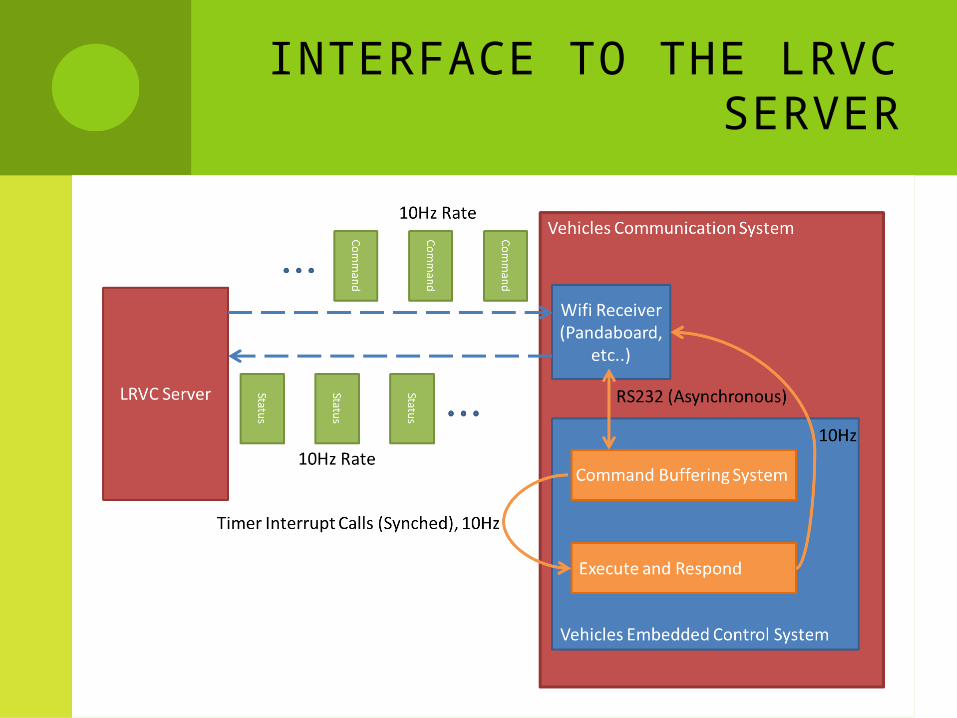
INTERFACE TO THE LRVC SERVER

EMBEDDED SYSTEMBuffer OpCodes
Async.Send Status Messages
10 Hz Timer Interrupt
Code
Command Flags Status Messages
8 Messages
36 Byte Max Msg Size
8 Commands (8 Bytes)
Execution Functions Construct Response Functions
Obst Det IRs (10) Battery Management
Trig Tables
Obstacle Detection
Alg.
Bat. Algo Variables
Battery Level Alg.
Receive Buffer (256)
1.
2.
3.
50 Hz Timer Interrupt
Code
Command Process
Obstacle Avoid.Process
Obstacle Avoid Alg.
Past Movements
And Obstacles

EMBEDDED SYSTEM – MEMORY MAPPING
Physical Address Variable Name Size Comment/Description0 Forward Flag 11 Backward Flag 12 Right Flag 13 Left Flag 14 Turret Right Flag 15 Turret Left Flag 16 Fire 17 Obstacle Det Flag 1
[8-295] Transmit Buffer 288[296-551] Receive Buffer 256
552 T_Buff_In Pointer 1 The tail of the transmit buffer553 T_Buff_Out Pointer 1 The head of the transmit buffer554 R_Buffer_In Pointer 1 The tail of the receive buffer

EMBEDDED SYSTEM – MEMORY MAPPING
Physical Address Variable Name Size Comment/Description555 R_Buffer_Out Pointer 1 The head of the receive buffer556 Battery Level 1
[557-560] Other Bat Op Vars 4[561-688] Sin Chart 128 For Obstacle Det.[689-816] Cos Chart 128 For Obstacle Det.
817 Forward Drop Off 1 ATD Val of forward dropoff sensor, might not be needed818 Backward Drop Off 1 ATD Val of backword dropoff sensor, might not be needed819 Radar1 X 1820 Radar1 Y 1
[821-832] … 12 Radar2 - 7 X,Y variables833 Radar8X 1834 Radar8Y 1835 BatteryMin 1 Defines the point where the user is notified of low battery836 SensorThreshold 1 Defines when an obstacle is offi cially detected.
[837-872] Response 36 An array of bytes used to construct and send Status message responses

PowerSupply
PowerSupply
PowerSupply
PowerSupply
External Oscillation
JTAG(ULinkMe)
Left Drive
Motor
Right Drive Motor
Turret Drive Motor
Fire
Ledge Det.
Obstacle Det.Panda Comm
(UART)
Reset
Bat ManagementComm (UART)
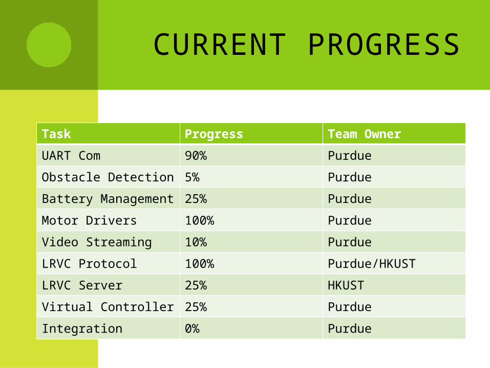
CURRENT PROGRESS
Task Progress Team Owner
UART Com 90% Purdue
Obstacle Detection 5% Purdue
Battery Management 25% Purdue
Motor Drivers 100% Purdue
Video Streaming 10% Purdue
LRVC Protocol 100% Purdue/HKUST
LRVC Server 25% HKUST
Virtual Controller 25% Purdue
Integration 0% Purdue

QUESTIONS?


