Software Requirements Specification (SRS) Project Active Park Assist 2 Authors: Joseph Reeder, Ethan Ettema, Ryan Boyce, Kenneth Massie, Stephanie Brown Customer: Ford Motor Company Instructor: Dr. Betty Cheng Introduction This SRS will cover the Active Park Assist feature that will be in Ford’s new Lincoln lines. The purpose, constraints, requirements, and prototyping will all be covered in this document, along with models for the system’s operation. 1.1 Purpose This document’s purpose is to provide a detailed description of the Active Park Assist system for Ford Motor Company. Throughout the document, the purpose and features of the system, the user-interface of the system, how the system will respond to various scenarios, the system constraints, the design assumptions and dependencies, and finally the system requirements will all be presented. This document is intended for both Ford Motor Company and the system developers, and will be proposed to Ford Motor Company for their approval.
Transcript
Software Requirements Specification (SRS)
Project Active Park Assist 2
Authors: Joseph Reeder, Ethan Ettema, Ryan Boyce, Kenneth Massie, Stephanie Brown
Customer: Ford Motor Company
Instructor: Dr. Betty Cheng
Introduction This SRS will cover the Active Park Assist feature that will be in Ford’s new Lincoln lines. The purpose, constraints, requirements, and prototyping will all be covered in this document, along with models for the system’s operation. 1.1 Purpose This document’s purpose is to provide a detailed description of the Active Park Assist system for Ford Motor Company. Throughout the document, the purpose and features of the system, the user-interface of the system, how the system will respond to various scenarios, the system constraints, the design assumptions and dependencies, and finally the system requirements will all be presented. This document is intended for both Ford Motor Company and the system developers, and will be proposed to Ford Motor Company for their approval.
1.2 Scope The software system proposed is an active park assist system for Ford Motor Company. This system will be designed to assist drivers of Ford vehicles in parking the vehicle by allowing the driver to choose a parking spot, and automating nearly all of the parking process. By maneuvering the vehicle using various sensors, the braking system, the acceleration system, and the steering system, the active park assist system aims to reduce collisions that might otherwise occur from manual parking, while relieving stress of the driver.
More specifically, this system will present the driver with the option to park in a spot either parallel or perpendicular to the vehicle, and will also search for an available spot. Once an available spot is detected, the system will require the driver to confirm the spot. Once confirmed, the system will take complete control over parking the vehicle, notifying the driver once the parking process has been successfully completed (or aborted) and will disengage from controlling the various vehicle subsystems.
1.3 Definitions, Acronyms, and Abbreviations In the table below, various acronyms, abbreviations, and phrases that are used throughout this document are defined.
Term Definition Acceleration System Vehicle system which controls the acceleration of
the vehicle vis the vehicle’s engine Active Park Assist (APA)
The name of the system
Braking Subsystem Vehicle subsystem which controls the deceleration of the vehicle via the vehicle’s brakes
Client Ford Motor Company Customer See client
Driver Person operating the vehicle equipped with the APA system
Human Machine Interface (HMI) Interface between the system and the driver
MPH Miles per hour
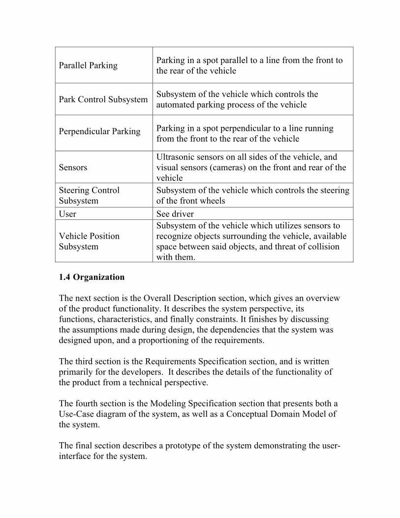
Parallel Parking Parking in a spot parallel to a line from the front to the rear of the vehicle
Park Control Subsystem
Subsystem of the vehicle which controls the automated parking process of the vehicle
Perpendicular Parking Parking in a spot perpendicular to a line running
from the front to the rear of the vehicle
Sensors Ultrasonic sensors on all sides of the vehicle, and visual sensors (cameras) on the front and rear of the vehicle
Steering Control Subsystem
Subsystem of the vehicle which controls the steering of the front wheels
User See driver
Vehicle Position Subsystem
Subsystem of the vehicle which utilizes sensors to recognize objects surrounding the vehicle, available space between said objects, and threat of collision with them.
1.4 Organization The next section is the Overall Description section, which gives an overview of the product functionality. It describes the system perspective, its functions, characteristics, and finally constraints. It finishes by discussing the assumptions made during design, the dependencies that the system was designed upon, and a proportioning of the requirements. The third section is the Requirements Specification section, and is written primarily for the developers. It describes the details of the functionality of the product from a technical perspective. The fourth section is the Modeling Specification section that presents both a Use-Case diagram of the system, as well as a Conceptual Domain Model of the system. The final section describes a prototype of the system demonstrating the user-interface for the system.
All sections of the document describe the same software system, but are intended for different audiences and thus use different language. Sections one, two, and five are directed towards both the client as well as the developers, whereas sections three through five are specifically directed towards the developers. 2 Overall Description The intent of this section is to give an overview of the APA system. This overview will include the functionality of the system as well as the expectations of those who use it. Constraints, assumptions, and dependencies for the system will be explained, followed by requirements of the system that are deemed to be beyond the scope of this project. 2.1 Product Perspective
This system will be in place to help coordinate several other subsystems within the vehicle to perform its functions. As showen in Figure 1 below, the APA system will include the HMI subsystem and will interact with the park control, brake, steering, and vehicle position subsystems. The vehicle position system will include a network of peripheral cameras and sensors that will aid in the system’s function as well. The HMI will accept input from the user, provide visuals for any system warnings, and display live video it receives from peripheral cameras. The park control system will then use input acquired from HMI along with information from the vehicle position system to calculate vehicle trajectory and issue commands to the other subsystems. The steering control, brake control, and power management systems will receive input from the park control system necessary to perform the parking trajectories calculated. The power management system will work to shift gears and accelerate the vehicle while the brake system will be used to decelerate the vehicle. Finally, the steering control system will be used to maneuver the vehicle.
Figure 1. Data Flow Diagram: Representing the flow of information throughout the APA system
2.2 Product Functions
The primary function of the APA system is to assist the user with parking safely and accurately. Upon activation, the user will be prompted for which type of spot they wish to find, either parallel or perpendicular. To aid the user in finding a spot for a given type of parking, the system will scan for and present potential parking spaces to users through visuals on HMI while
APA System
HMI
Park Control Vehicle Position
Cameras / Sensors
Feedback User Input
Powertrain Management Steering Control Brake Control
Commands
Queries
Data
Feedback
System Feedback
Key
Data Flow
Subsystem
the user is driving. The user will then interact with the HMI’s touchscreen to select a desired spot. Once a spot is verified, the system will calculate the optimal path to the spot and activate the parking maneuver. Several subsystems will then work together to shift gears, accelerate / decelerate, and steer the vehicle to follow the calculated path. All throughout this process, sensors and cameras will be active on the vehicle to help detect potential obstacles and to relay feedback to the APA system. The feedback that the APA system receives will constantly be monitored so that the system can continue to make adjustments as necessary as the maneuver continues. If an obstacle is detected, the system will stop the vehicle to avoid collisions. Once the path is clear of obstacles, the user can reactivate the parking process through the HMI and the system will complete the parking maneuver and shift the car into park for the user. Upon completion, the HMI will confirm to the user that the maneuver has been successfully completed. 2.3 User Characteristics
The system is intended for use by the operator of the vehicle, therefore a user of the system must be legally allowed to operate a vehicle according to the laws applicable where they live. The simple touchscreen process of the HMI will allow for users of varying backgrounds and skill levels to activate and provide the inputs for system operation. 2.4 Constraints
For proper operation, the HMI software must be able to communicate with the embedded systems of the subsystems involved. If the system is active for an extended period, operations will be aborted and the user will have to reinitiate the sequence. This causes the constraint that APA maneuvers be performed within 75 seconds. To aid in preventing malicious use, the systems will be using a seed and key system in which one module will provide a question that another module must answer correctly to communicate safely.
The system will be constrained to vehicles with shift by wire transmissions, as it is a requirement of the system to shift gears for operation. As a safety constraint, if any hardware component of any of the subsystems fails, the user will not be able to activate the APA system. Another safety constraint is that the system must avoid collision with obstacles that are detected via sensors during parking maneuvers.
2.5 Assumptions and Dependencies
One assumption of a user is that they will be familiar with touchscreen devices and interacting with them. It is also expected that the user be legally allowed to drive (proper vision, age, etc.). Although the system has been optimized to handle as many situations as possible, the ability to override the system exists and therefore assumes the user to have the ability to practice proper judgment given unique scenarios. As the system is comprised of a number of subsystems, it will be assumed that all of the subsystems perform their functionality as expected. Although this system will detect failures and subsequently prevent itself from operating, it is expected that hardware components of the subsystems have their own failsafe procedures in place as well.
2.6 Approportioning of Requirements Based on negotiations and time constraints, we are to assume the proper functioning of subsystem components for the project at hand. These considerations may be included in future releases time permitting. 3 Specific Requirements This section describes the requirements of the system, and is divided into four subsections. General requirements are requirements that must be met in order for the system to operate. HMI requirements refer to specific features that the HMI must have. APA requirements refer to requirements that must be met by other subsystems. Safety requirements are overall requirements that must be adhered to in order for the system to operate in a safe manner.
3.1 General
3.1.1. Sensors
a. The vehicle must have ultrasonic sensors on both sides b. The vehicle must also have cameras in the rear and front c. The system must be able to use the ultrasonic sensors to
calculate the distance between two objects 3.1.2. System activation
a. The vehicle must be stopped in order to engage the system b. Once engaged, the driver must then drive forward slowly
(around 2.5 mph) until a spot has been detected c. Once detected, the driver must confirm via the HMI that the
detected spot is where they would like to park d. In order to activate a parking maneuver, the driver must first
apply the brakes, and then shift into the neutral gear 3.1.3. The parking process must be carried out within 75 seconds, or else
the system will abort 3.1.4. The system must shift the vehicle into the neutral gear when the
process successfully completes 3.1.5. The system must deactivate, returning control to the customer,
when the process successfully completes 3.1.6. The system will be unavailable if a trailer is attached to the
vehicle
3.2 HMI
3.2.1. The customer must activate the Active Park Assist Feature through the HMI
3.2.2. The customer must be able to select between parallel and perpendicular parking
3.2.3. Parking selection a. The HMI must display available parking spots b. The customer must be able to verify which spot they would like to
choose to park in 3.2.4. The HMI must indicate to the customer the current state of the
parking process a. The HMI will display the current trajectory and progress along it b. The HMI must indicate if the process was completed successfully c. The HMI must indicate if the process was aborted
3.2.5. The HMI must display any warnings associated with system failure or collisions
3.3 Active Park Assist System
3.3.1. The system must be able to take full control of the vehicle driving capabilities a. The system must be able to accelerate the vehicle b. The system must not accelerate the vehicle to a speed greater than
or equal to 5mph c. The system must be able to brake the vehicle d. The system must be able to steer the vehicle e. The vehicle must be able to shift the vehicle into reverse, forward
and neutral 3.3.2. Parking detection
a. While parallel parking, the system must be able to identify a parking spot if it is 1.2 times the length of the vehicle
b. The system will remember previously detected parking spots and trajectory if it was recently aborted so that it can resume if required
3.4 Safety
3.4.1. The vehicle must be stopped in order to activate the system 3.4.2. The system should have a speed cap of 5 mph, and ignore when
the customer presses the accelerator 3.4.3. The system must have the ability to pause and abort
a. The customer must be able to abort the parking process by applying the brake pedal
b. The customer may abort by turning the steering wheel c. The customer may also abort by shifting the vehicle into park d. If the customer aborts the process, then the system must shift the
car back to neutral e. If one of the vehicle doors is opened, then the system should
pause and continue once the door has been closed again 3.4.4. The system must detect obstacles in the path of the vehicle
a. The system must be able to prevent the vehicle from hitting any obstacles while in the parking process
b. If there is an object in its path, then the system will apply the brakes until the customer either aborts or chooses to continue
c. Any collision will abort the system 3.4.5. The system must verify that the customer initiated the request 3.4.6. The system must detect faults in the system
a. The system must be able to detect a single point failure of any sensor
b. If a sensor is obstructed, the customer should be notified via the HMI that the system cannot perform its job
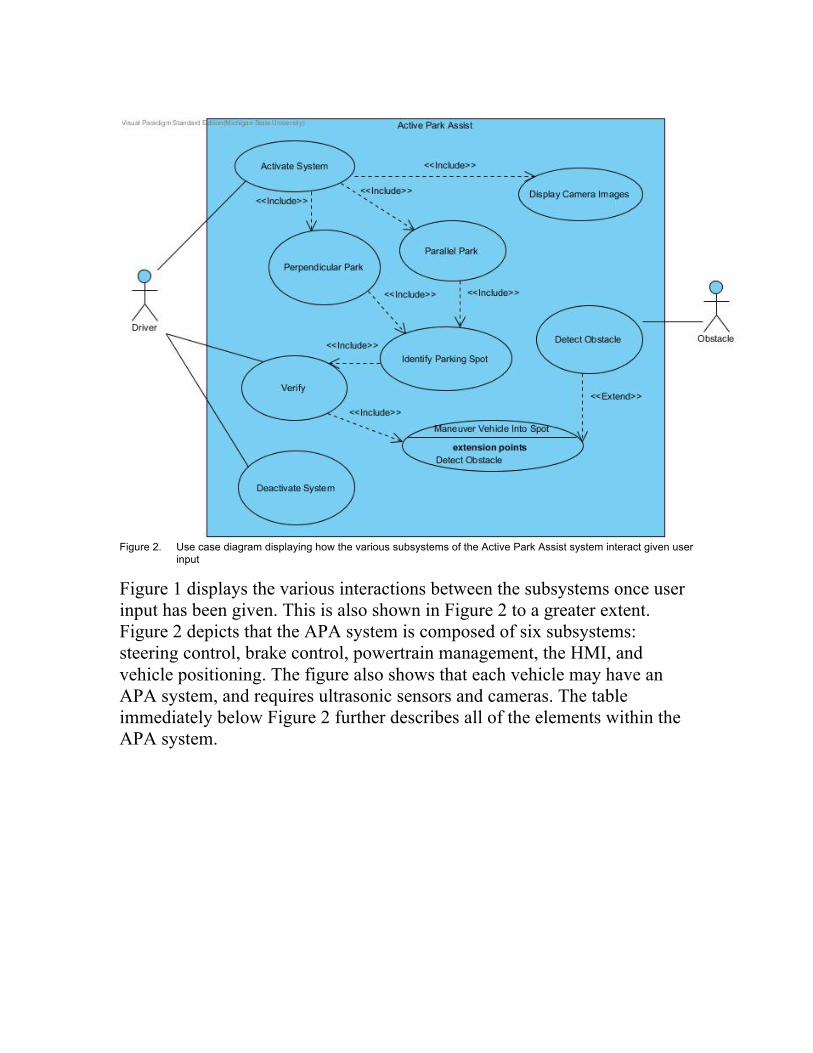
4 Modeling Requirements A use case diagram for the Active Park Assist system is shown in Figure 1. In this diagram, the only actors who interact with the system are the driver of the vehicle and any object that may obstruct the path of the vehicle. An obstructing object only interact indirectly with the system in that, once they are detected, the system notifies the driver of the obstacle and halts the maneuver as noted in Section 3.4.4. Apart from aborting the system via the steering wheel, brakes, or accelerator, the driver can only interact with the system via the HMI. The driver's options include activating the system and choosing the type of parking maneuver, either perpendicular or parallel. The driver can then verify a parking space, which is displayed on the HMI, as noted in Section 3.2.3. At any time, the driver may choose to deactivate the system.
Figure 2. Use case diagram displaying how the various subsystems of the Active Park Assist system interact given user input
Figure 1 displays the various interactions between the subsystems once user input has been given. This is also shown in Figure 2 to a greater extent. Figure 2 depicts that the APA system is composed of six subsystems: steering control, brake control, powertrain management, the HMI, and vehicle positioning. The figure also shows that each vehicle may have an APA system, and requires ultrasonic sensors and cameras. The table immediately below Figure 2 further describes all of the elements within the APA system.
Figure 3. Conceptual domain model depicting interactions between key elements of the system
Data Dictionary Class
Name Driver Description The person that gives the system commands via the HMI Driver Relationships
Class Description HMI The driver gives commands to the HMI. Class
Name HMI
Description The main interface. It tells the park control subsystem which operation to perform, and also displays information to the driver.
HMI Operations Name of Operation Description turnOn() Activates the system. turnOff() Deactivates the system.
verify(userInput : Boolean)
The driver must either confirm or deny and action with the system.
parallelPark() The driver has chosen to parallel park. perpendicularPark() The driver has chosen to perpendicular park. displayTrajectory() The HMI displays the current path of the vehicle. displayWarning() Displays a message when an error occurs. displaySuccess() Displays a message when a maneuver is completed. HMI Relationships
Class Name Description Driver Driver gives commands to the HMI.
Park Control The HMI gives commands to the Park Control subsystem. It also receives commands from this subsystem.
Vehicle Position The HMI displays imaging data from the Vehicle Position subsystem.
Class
Name Park Control
Description The main subsystem. It calculates vehicle trajectory and commands many of the other subsystems.
Park Control Operations Name of Operation Description
parallelPark() The system attempts to perform a parallel park maneuver.
perpendicularPark() The system attempts to perform a perpendicular park maneuver.
calculateTrajectory() Using information from the vehicle position subsystem, calculates the best path into the parking spot.
obstacleDetected() Stops the vehicle when an obstacle has been detected. Park Control Relationships
Class Name Description
HMI The Park Control subsystem receives commands from the HMI. It also gives commands to the HMI.
Vehicle Position Requests positioning data from the Vehicle Position subsystem and calculates the trajectory based upon it.
Powertrain Management
Gives commands to the Powertrain Management subsystem. This includes shifting gears, accelerating, and decelerating.
Brake Control Gives commands to the Brake Control subsystem. This includes depressing and releasing the brakes.
Steering Control Gives commands to the steering control, turning the steering wheel.
Class
Name Vehicle Position
Description Takes in data from the cameras and ultrasonic sensors, then sends it to the Park Control subsystem.
Vehicle Position Operations Name of Operation Description
identifySpace() Attempts to identify a space large enough for the vehicle to park in.
verifyPosition() Confirms the position of the vehicle to the Park Control subsystem.
Vehicle Position Relationships
Class Name Description
Park Control Supplies positioning information to the Park Control subsystem.
HMI Gives imaging data to the HMI. Camera Receives environmental data from cameras. Ultrasonic Sensor Receives environmental data from sensors. Class
Name Powertrain Management Description Controls the acceleration of the vehicle as well as gear shifts. Powertrain Management Operations Name of Operation Description shiftGear() Shifts the gear into either reverse or neutral. accelerate() Accelerates the vehicle. decelerate() Decelerates the vehicle.
Powertrain Management Relationships Class Name Description
Park Control Accepts commands from the Park Control subsystem. Class
Name Brake Control Description Controls the vehicle's brakes. Brake Control Operations Name of Operation Description depressBrake() Brakes the vehicle. releaseBrake() Releases the vehicle's brakes so it can move. Brake Control Relationships
Class Name Description Park Control Accepts commands from the Park Control subsystem. Class
Name Steering Control Description Controls the vehicle's steering. Steering Attributes
Name of Attribute Description
degreesRotation An integer value that keeps track of the current rotation of the steering wheel.
Steering Operations
Name of Operation Description turn(degrees : Integer) Turns the steering wheel the specified amount. Steering Relationships
Class Name Description Park Control Accepts commands from the Park Control subsystem. Class
Name Camera Description Takes in visual data from the vehicle's surroundings.
Camera Relationships Class Name Description
Vehicle Position Supplies environmental data to the Vehicle Position subsystem.
Class
Name Ultrasonic Sensor Description Takes in data from the vehicle's surroundings. Ultrasonic Sensor Relationships
Class Name Description
Vehicle Position Supplies environmental data to the Vehicle Position subsystem.
In addition, Figure 2 explains the relationships between the subsystems as well. When the APA system has been activated via the HMI, its various subsystems are also activated. The vehicle position subsystem is supplied with data from the ultrasonic sensors and cameras, and calculates the vehicle trajectory for the park control subsystem. The park control subsystem controls the steering, brake, and powertrain management subsystems in order to maneuver the vehicle. It also takes input from the HMI in order to determine which parking maneuver it should be performing. The HMI displays visual data from the camera combined with the vehicle trajectory when a maneuver is in progress. In an example scenario, the driver activates the system and chooses to parallel park via the HMI. The HMI then identifies to the driver an available parking spot, and the driver would verify it. At this point, the park control subsystem takes over steering, acceleration, and brakes, maneuvering the vehicle into the correct position. Assuming the maneuver was completed successfully, control of the vehicle is returned to the driver. This scenario is displayed in Figure 3.
Figure 4. Sequence diagram of first example scenario where a parallel park maneuver is successfully completed by the system.
Another example scenario starts out much the same, except the system encounters an obstacle during the maneuver. The system stops the vehicle and notifies the driver. The driver then verifies that the system should not continue. This scenario is displayed in Figure 4.
Figure 5. Sequence diagram of the second example scenario, depicting what happens if the system detects an obstacle while it is maneuvering into a parking spot.
Figure 5 shows the overall behavior of the HMI and the APA system that the user will use for initiating the feature. Starting at the home page of the HMI, the user can select the parking type desired and the system will begin searching for a viable parking spot. Upon locating a valid parking spot, the user can choose to reject the spot and have the system continue searching for a new spot, or can accept the parking spot. If accepted, the system will begin the active park assist process, pausing if an object moves into the path of the vehicle or aborting the process if the brake is applied or a timeout occurs. Upon completion, the HMI will display a completed screen and will return the user back to the HMI homepage.
Figure 6. A state diagram of the systems that showing the behavior of the system, capturing the system’s overall operation and state. 5 Prototype This prototype shows the events that would occur throughout the process of the APA feature. The prototype provides the interface that the user would interact with, as well as allows the user of the prototype to provide other external factors such as the event where the user pushes the brake and the system timing out. 5.1 How to Run Prototype To run the prototype, the user needs to have access to the internet and be able to access the webpage,
http://www.cse.msu.edu/~cse435/Projects/F2014/Groups/APA2/web/PrototypeV1/ProtoV1.html. The prototype is entirely web-based and provides the series of events that the HMI would progress through while the APA feature is operating. The prototype will start the user at the main screen of the HMI. The only button selection on the main screen that will function is the APA button, or the button with the “P” for its text. The user will then have the option to select either parallel parking assistance or perpendicular parking assistance. Once an option is selected, the prototype will show that the system is scanning for a parking spot. After a parking spot is located, the user will then have the option to either accept the parking spot or reject the parking spot. If the user rejects the parking spot, the system will begin the scanning process again. If the user accepts the parking spot, then the prototype will show that the system is in the process of parking the vehicle. At any time if the user selects the external option of pushing the brake, the system will abort and the process will conclude. Similarly, if the process timeout option is selected, indicating that the process has not completed in the given amount of time, the process will abort and conclude. Upon a successful parking process, the HMI will display that the process was carried out successfully and the parking process will return full control back to the user (indicated by returning to the HMI home page of the prototype). 5.2 Sample Scenarios The driver wishes to park perpendicularly in a parking spot located in a parking lot. As the driver approaches their destination, the driver activates the parking functionality by pressing the “P” located in middle of the bottom row of the main screen as shown in Figure 7.
Figure 7. HMI main screen After the driver invokes the parking system, the driver will be given the option to select which type of parking feature to execute as can be seen in Figure 8. The driver chooses “Perpendicular Parking”.
Figure 8. Parking feature selection
After perpendicular parking has been selected, APA will now enter a scanning mode that can be seen in Figure 9. The vehicle is traveling at 5 miles per hour, which is adequate for the system to execute. When the driver approaches an available parking space, the HMI will display what is shown in Figure 10. This screen informs the driver that an available perpendicular parking spot has been found and gives the driver the option to accept or reject what the system has found. The driver accepts the spot and as a result the HMI screen changes to a live display of what is behind the vehicle as the maneuver is completed (seen in Figure 11).
Figure 9. HMI while scanning for a perpendicular parking spot
Figure 10. HMI indicating an available spot has been found
Figure 11. HMI live camera as vehicle is reversing
After the process is completed, the HMI will now display a screen (figure 12) confirming the process has completed. The vehicle will now be in park.
Figure 12. HMI informing use the process is completed
6 References
[1] Land Rover USA. “2014 Range rover Evoque Park Assist | Land Rover USA.” YouTube. YouTube, 17 June 2014. Web. 14 October 2014.
[2] G. Spencer (2010, March 11). Intelligent Parking Assist for Toyota Prius [Online]. Available: http://www.cnet.com/news/intelligent-parking-assist-for-toyota-prius/ [3] G. Straton. (2012, October 16). 2012 Toyota Prius V – Cutting it close [Online]. Available: http://www.chicagonow.com/drive-he-said/2012/10/2012-toyota-prius-v-cutting-it-close-aka-guided-parallel-parking-video/
Point of Contact For further information regarding this document and project, please contact Prof. Betty H.C. Cheng at Michigan State University (chengb at cse.msu.edu). All materials in this document have been sanitized for proprietary data. The students and the instructor gratefully acknowledge the participation of our industrial collaborators.