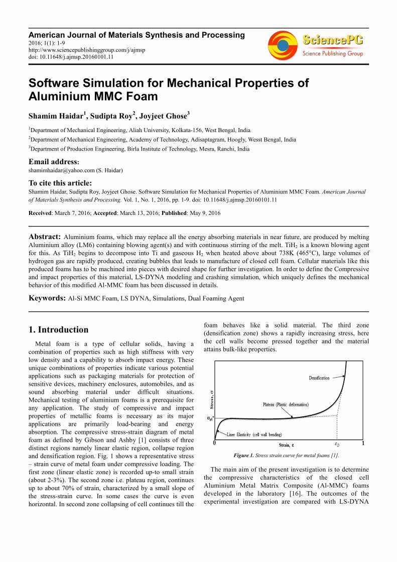
American Journal of Materials Synthesis and Processing 2016; 1(1): 1-9 http://www.sciencepublishinggroup.com/j/ajmsp doi: 10.11648/j.ajmsp.20160101.11 Software Simulation for Mechanical Properties of Aluminium MMC Foam Shamim Haidar 1 , Sudipta Roy 2 , Joyjeet Ghose 3 1 Department of Mechanical Engineering, Aliah University, Kolkata-156, West Bengal, India 2 Department of Mechanical Engineering, Academy of Technology, Adisaptagram, Hoogly, Wesst Bengal, India 3 Department of Production Engineering, Birla Institute of Technology, Mesra, Ranchi, India Email address: [email protected] (S. Haidar) To cite this article: Shamim Haidar, Sudipta Roy, Joyjeet Ghose. Software Simulation for Mechanical Properties of Aluminium MMC Foam. American Journal of Materials Synthesis and Processing. Vol. 1, No. 1, 2016, pp. 1-9. doi: 10.11648/j.ajmsp.20160101.11 Received: March 7, 2016; Accepted: March 13, 2016; Published: May 9, 2016 Abstract: Aluminium foams, which may replace all the energy absorbing materials in near future, are produced by melting Aluminium alloy (LM6) containing blowing agent(s) and with continuous stirring of the melt. TiH 2 is a known blowing agent for this. As TiH 2 begins to decompose into Ti and gaseous H 2 when heated above about 738K (465°C), large volumes of hydrogen gas are rapidly produced, creating bubbles that leads to manufacture of closed cell foam. Cellular materials like this produced foams has to be machined into pieces with desired shape for further investigation. In order to define the Compressive and impact properties of this material, LS-DYNA modeling and crashing simulation, which uniquely defines the mechanical behavior of this modified Al-MMC foam has been discussed in details. Keywords: Al-Si MMC Foam, LS DYNA, Simulations, Dual Foaming Agent 1. Introduction Metal foam is a type of cellular solids, having a combination of properties such as high stiffness with very low density and a capability to absorb impact energy. These unique combinations of properties indicate various potential applications such as packaging materials for protection of sensitive devices, machinery enclosures, automobiles, and as sound absorbing material under difficult situations. Mechanical testing of aluminium foams is a prerequisite for any application. The study of compressive and impact properties of metallic foams is necessary as its major applications are primarily load-bearing and energy absorption. The compressive stress-strain diagram of metal foam as defined by Gibson and Ashby [1] consists of three distinct regions namely linear elastic region, collapse region and densification region. Fig. 1 shows a representative stress – strain curve of metal foam under compressive loading. The first zone (linear elastic zone) is recorded up-to small strain (about 2-3%). The second zone i.e. plateau region, continues up to about 70% of strain, characterized by a small slope of the stress-strain curve. In some cases the curve is even horizontal. In second zone collapsing of cell continues till the foam behaves like a solid material. The third zone (densification zone) shows a rapidly increasing stress, here the cell walls become pressed together and the material attains bulk-like properties. Figure 1. Stress strain curve for metal foams [1]. The main aim of the present investigation is to determine the compressive characteristics of the closed cell Aluminium Metal Matrix Composite (Al-MMC) foams developed in the laboratory [16]. The outcomes of the experimental investigation are compared with LS-DYNA
Transcript
American Journal of Materials Synthesis and Processing 2016; 1(1): 1-9
http://www.sciencepublishinggroup.com/j/ajmsp
doi: 10.11648/j.ajmsp.20160101.11
Software Simulation for Mechanical Properties of Aluminium MMC Foam
Shamim Haidar1, Sudipta Roy
2, Joyjeet Ghose
3
1Department of Mechanical Engineering, Aliah University, Kolkata-156, West Bengal, India 2Department of Mechanical Engineering, Academy of Technology, Adisaptagram, Hoogly, Wesst Bengal, India 3Department of Production Engineering, Birla Institute of Technology, Mesra, Ranchi, India
LS-DYNA is the only software which is having ‘foam’ in
its materials library. It also includes the Honeycomb and
Modified Honeycomb. The unique characteristics of a metal
foam (as Density before and after compression, Average Cell
wall thickness, etc.) can be fed to the software. So, the
required equations of the material behaviors to solve a given
problem are not necessary to provide all the times. When the
material is defined it can automatically recall the material
properties equations to run the analysis. For this current work
modified honeycomb material was needed, which is available
only in this software and the required simulations (drop test
and compression) on desired materials can also be done here.
So, mainly for the ease of work and available working
facility with required material (modified honeycomb), this
software LS-DYNA is chosen.
Required Inputs: All input files are in simple ASCII
format and thus can be prepared using any text editor. Input
files can also be prepared with the aid of a graphical
preprocessor such as Ansys, Pro-E, Catia etc. Though, LS-
DYNA has its own preprocessor named LS-Prepost. First of
all a CAD model is produced. Then loading condition [the
amount of force with directions, kind of force (concentrated
or distributed, explosive or static), nodes (location) where
the force is applied] is applied on the model. Input files are
saved in. k or. iges file format and then fed to the LS-
DYNA for analysis.
Outputs: After the analysis is done, the outputs are found in
ASCII (glstat, matsum) format and also in. binout, XY Data
etc. Stresses of each element in different directions, change of
different energies (kinetic, sliding, internal, total etc.), strains,
with respect to time can be achieved by the analysis.
3.2. Simulations
The sample, which was fabricated using pre treated TiH2
(480°C, 60 mins) experimentally found out as best in quality
for energy absorption during compression. The measured
properties of foam material is chosen as a ‘test material’ and
steel is chosen as rigid material with density (ρ) = 7850
Kg/m3, elastic modulus (E) = 200 GPa and poison’s ratio =.
5. The values taken as input are given below in table 1.
3.3. Impact Test Simulations
Table 1. Material Properties used in LS-DYNA simulation.
Properties Unit
Closed Cell
Aluminium
Foam
Rigid
Material
(Steel)
Solid
Aluminium
Density (ρ) Kg/mm3 .54405x10-6 7.85x10⁻⁶ 2.7x10⁻⁶
Elastic
Modulus (E) KN/mm2 .115 200 70
Poison’s
Ratio (µ) Nil .32 .5 0.39
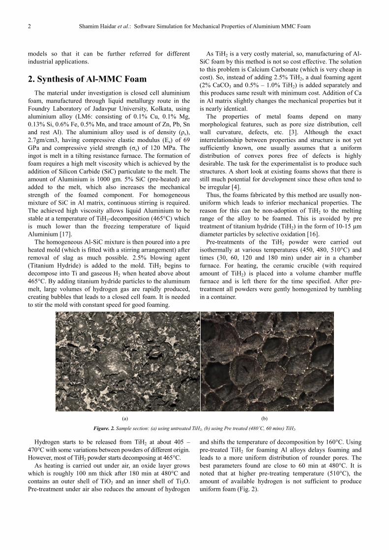
Two spheres of 25mm radius are modeled first. One of
them (solid sphere) is modeled using the properties of solid
aluminium (LM6) metal. The other one is made of modified
honeycomb material (foam sphere). Properties of the foam,
achieved from the experiments, are assigned for the foam
sphere. The properties used as input is given above in table 1.
The LS-DYNA set up is shown in figure 3.
The spheres are then set to impact on a (set as perfectly rigid)
plate made of steel with same and constant velocity 10mm/sec.
It has been seen that the solid sphere bounce back from the rigid
plate after the collision and the foam sphere crashes. This LS-
DYNA graphical is also given below in figure 4.
The rate of change of different energies with respect to
time are found and plotted from the LS-DYNA software.
Change of velocities with respect to time are also found and
plotted by the software.
The rate of change of total kinetic energy of solid sphere is
found out from figure 5. The rate of change of total kinetic
energy of foam sphere is found out from figure 6. Figure 7
shows the Curve of Change of Total Internal Energy of solid
sphere w. r. t. Time. Curve of Change of Total Internal Energy
of Foam sphere w. r. t. Time is plotted in Figure 8. Figure 9 and
10 shows the Displacement of CG of Solid sphere and Foam
sphere respectively with respect to time.
4 Shamim Haidar et al.: Software Simulation for Mechanical Properties of Aluminium MMC Foam
Figure 3. The set up of spheres and plate in LS-DYNA.
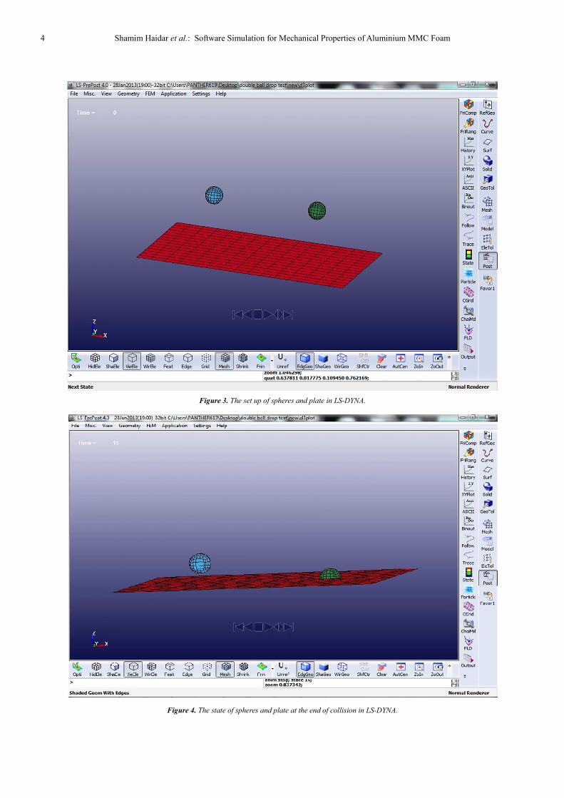
Figure 4. The state of spheres and plate at the end of collision in LS-DYNA.
American Journal of Materials Synthesis and Processing 2016; 1(1): 1-9 5
Figure 5. Curve of Change of Total Kinetic Energy of solid sphere w. r. t.
Time.
Figure 6. Curve of Change of Total Kinetic Energy of foam sphere w. r. t.
Time.
Figure 7. Curve of Change of Total Internal Energy of solid sphere w. r. t.
Time.
Figure 8. Curve of Change of Total Internal Energy of Foam sphere w. r. t.
Time.
Figure 9. Curve of Z displacement of solid sphere w. r. t. Time.
Figure 10. Curve of Z displacement of foam sphere w. r. t. Time.
From figure 9 the co-efficient of restitution of solid sphere
can be found out as given below.
It is known that,
Co-efficient of Restitution of solid sphere = 2
1
h
h, (1)
Where h1= height of releasing the object from datum line,
h2 = height from datum line up to which the object will
bounce up after collision with bodies at datum line.
So, the co-efficient of restitution of solid sphere =
91 15
150 15
−−
=0.7503
It is observed that the solid aluminium sphere is bouncing
back from the rigid surface that means enough energy is
absorbed to be used in automobile or packaging industries,
thus does not fulfill the requirement. But the aluminium foam
sphere is getting crushed and absorbing energies with more
quantity comparatively with solid one. It can be also proven
from the curve shown in figure 10. Thus the objective of this
present work is successfully fulfilled.
3.4. Crashing Simulation
Aluminium foam is normally used in crash box which is
placed in front of the chassis of a racing car. Crash box is a
hollow extruded parts produced by aluminium or fabricated
by aluminium sheet metals. The chance of survival of a
driver in an accident is achieved by a combination of the
crash resistance of the car and its ability to absorb energy.
This has been achieved by providing a survival cell (the
6 Shamim Haidar et al.: Software Simulation for Mechanical Properties of Aluminium MMC Foam
chassis) which is extremely resistant to damage, around
which energy absorbing devices are placed at strategic points
on the vehicle. The energy absorbing devices operate to
enable maximum deformation up to a specified limit. The
devices used are designed to dissipate energy irreversibly
during the impact, thereby reducing the force and momentum
transferred to the survival cell and hence the driver. Since the
late 1980s FIA has introduced a series of regulations to
ensure that the cars conform to stringent safety requirements
and build quality. Each vehicle must satisfy a list of
requirements, in the form of officially witnessed tests, before
it is allowed to race.
There are two groups of tests that must be passed for a
frontal absorbing structure of a prototype. The first is a static
side load applied on a vertical and transversal plane passing
500 mm forward of the front wheel axle. A constant load of
2000 N must be applied to one side of the crash-box using a
pad. After 30 seconds of application, there must be no failure
of the structure or of any attachment between the crash-box
and the chassis. The second test defines the effectiveness of
the energy absorbing structure. The crash-box and the front
part of the survival cell must be subjected to an impact test
against a solid, vertical barrier. The front part of the chassis
to be tested must be solidly attached to the trolley. The total
weight of the trolley and test structures must be of 610 Kg
and the velocity of impact of 12 m/s. During the test
maximum average deceleration of the trolley must not exceed
25 g and the final deformation must be contained in the zone
situated more than 100 mm ahead of the driver’s feet.
Prototype manufacturing and testing of each configuration
would be too expensive in cost and time. For these reasons
corresponding FE models are generated with a minor effort
and are capable of predicting the structural behavior under
dynamic loads.
The finite element simulation of such structure was
performed in the usual three typical steps:
Building of a parametric model by means of the pre-
processor ANSYS, non-linear dynamic analysis with LS-
DYNA and post-processing using ANSYS for the
interpretation and visualization of the results. The total
system was obtained by the right combination of a crash-box
and a striking mass that impact a barrier (Figure 11). The
material models verified by previous sandwich component
test were incorporated into FE model of the crash-box. The
barrier and the moving mass were meshed with the element
type SOLID 164 and were also regarded as rigid body. The
contact interface type ‘nodes-to-surface’ is used for the
contact between the rigid barrier and the crash-box. This type
is selected in order to prevent penetration of the specimen’s
internal nodes could be in contact with the rigid platen during
the simulation procedure. In order to prevent sliding at the
proximal ends, a coefficient of friction of 0.39 incorporated
between the rigid body surface and the edges of the structure.
Moreover any self-contacts of the inner and the outer
surfaces of the crash-box are assumed frictionless. The
boundary condition refers to the barrier and to the moving
mass. The moving mass is modeled as a rigid body with five
constraints. There are no displacements along the model
global axes x and y, and no rotations about the three global
basic axes. Therefore, displacement along the z axis is only
permitted with a constant initial velocity of 12 m/s. The
nonlinear analysis using the LS-DYNA code is performed
setting the total duration of the modeled axial collapse
process and other control’s parameters. During the dynamic
tests displacements (Fig. 13) and forces were recorded.
Above crash simulation has been done assuming the
density aluminium foam is 544.05 Kg/m3 and its height is 12
mm. For reason of simplification, the cellular honeycomb
core structure is treated as a homogeneous material using its
effective orthotropic material properties. The honeycomb
material directions are defined as the foaming-direction, and
direction perpendicular to the foaming. The crash tests have
been done by using the data generated by stress & strain
under compression test, shear and bending diagram carried
out under virtual environment.
Similar drop-tests were carried out for Aluminium foam
(produced by using pre-treated TiH2 as a foaming agent along
with CaCO3) filled cube made of thin aluminium sheet metals
(Figure 12).
American Journal of Materials Synthesis and Processing 2016; 1(1): 1-9 7
(c)
Figure 11. (a) schematic diagram of a racing car (b) Numerical model crash box at the time of Collision. (c) Modeling of deformed shape of crash-box during
impact in two different times.
Figure 12. Experimental deformation.
Figure 13. Deceleration-time curve.
3.5. Compression Test Simulation
A cube of side 20 mm made of closed cell aluminium foam is modeled at first. Then load is applied on its upper surface and
lower surface kept as fixed. The set up of the box before compression is shown in figure 14.
Figure 14. Cube before compression in LS-DYNA.
8 Shamim Haidar et al.: Software Simulation for Mechanical Properties of Aluminium MMC Foam
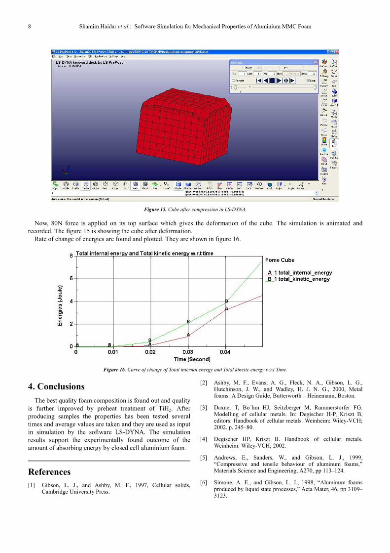
Figure 15. Cube after compression in LS-DYNA.
Now, 80N force is applied on its top surface which gives the deformation of the cube. The simulation is animated and
recorded. The figure 15 is showing the cube after deformation.
Rate of change of energies are found and plotted. They are shown in figure 16.
Figure 16. Curve of change of Total internal energy and Total kinetic energy w.r.t Time.
4. Conclusions
The best quality foam composition is found out and quality
is further improved by preheat treatment of TiH2. After
producing samples the properties has been tested several
times and average values are taken and they are used as input
in simulation by the software LS-DYNA. The simulation
results support the experimentally found outcome of the
amount of absorbing energy by closed cell aluminium foam.
References
[1] Gibson, L. J., and Ashby, M. F., 1997, Cellular solids, Cambridge University Press.
[2] Ashby, M. F., Evans, A. G., Fleck, N. A., Gibson, L. G., Hutchinson, J. W., and Wadley, H. J. N. G., 2000, Metal foams: A Design Guide, Butterworth – Heinemann, Boston.
[3] Daxner T, Bo¨hm HJ, Seitzberger M, Rammerstorfer FG. Modelling of cellular metals. In: Degischer H-P, Kriszt B, editors. Handbook of cellular metals. Weinheim: Wiley-VCH; 2002. p. 245–80.
[4] Degischer HP, Kriszt B. Handbook of cellular metals. Weinheim: Wiley-VCH; 2002.
[5] Andrews, E., Sanders, W., and Gibson, L. J., 1999, “Compressive and tensile behaviour of aluminum foams,” Materials Science and Engineering, A270, pp 113–124.
[6] Simone, A. E., and Gibson, L. J., 1998, “Aluminum foams produced by liquid state processes,” Acta Mater, 46, pp 3109–3123.
American Journal of Materials Synthesis and Processing 2016; 1(1): 1-9 9
[7] Lu, T. J., and Ong, J. M., 2001, “Characterization of close-celled cellular aluminum alloys,” J Mater Sci, 36, pp 2773–2786.
[8] Tzeng, S. C., and Ma, W. P., 2006, “A novel approach to manufacturing and experimental investigation of closed-cell Al foams,” Int J Adv Manuf Technol, 28, pp 1122–1128.
[9] Grenestedt, J. L., 1998, “Influence of wavy imperfections in cell walls on elastic stiffness of cellular solids,” J Mech Phys Solids, 46, pp 29–50.
[10] B. Matijasevic-Lux, et al., Modification of titanium hydride for improved aluminium foam manufacture, Acta Materialia, 54 (2006) 1887–1900.
[11] Sutradhar G. & Kumar S., “Metallic Foam – A Potential Material for the Future”, Indian Foundry Journal, Vol. 54, No.2, Feb. 2008.
[12] Ghose J, Sharma V, Kumar S., “Compressive behavioral analysis of Al-MMC foam”, International Journal of Industrial and production engineering & Technology, Vol 1, No. 1 (2011), pp 35-43.
[13] Mukai, T., Kanahashi, H., Miyoshi, T., Mabuchi, M., Nieh, T. G., and Higashi, K. 1999. Experimental Study of Energy
Absorption in A Close-Celled Aluminum Foam Under Dynamic Loading. Scripta Materialia. Vol. 40, No. 8, pp. 921–927.
[14] Reid, S. R. and Peng, C., 1997, Dynamic uniaxial crushing of wood. International Journal of Impact Engineering. 19(5-6): p. 531-570.
[15] S Haidar, S. C. Mandal, G. Sutradhar, “Electrical Conductivity of Aluminium-SiCp foam by Stir-casting Technique Using Dual Foaming Agent”; International Journal for Research in Emerging Science and Technology, Vol- 2, Issue -2, (2015) pp 62-67.
[16] S. Haidar, J. Ghose, G. Sutradhar, “Synthesis and Compressive Characterization of Aluminium-SiCp Composite foam by Stir-casting Technique Using Dual Foaming Agent”; International Journal of Advanced Information Science and Technology, Vol-36, No-36, (2015) pp 1-6.
[17] S Haidar, S Ansary and A Rahman, “Production and Compressive Characterization of Aluminium MMC Foam Manufactured Using Dual Foaming Agents”, IOP conf. Series: Materials Science and Engineering 115 (2016) 012030.