114
BA 001 N/08/en/02.02 Software Version 4.25 for NMS53x Proservo NMS53x Series Operating Manual Endress+Hauser Systems & Gauging

BA 001 N/08/en/02.02Software Version 4.25 for NMS53x Proservo
NMS53x Series
Operating Manual
Endress+HauserSystems & Gauging
Sakura Endress 1
Proservo NMS53x Table of Contents
Table of ContentsGeneral Notes .................................................................. 2
1 Safety Instructions .................................................... 3
2 System Configuration .............................................. 5
3 Specifications and Dimensions ............................... 83.1 Typical Specifications .................................... 83.2 Dimensions .................................................... 9
4 Necessary Tools for Installation ............................ 10
5 Mounting .................................................................. 115.1 Application drawings for tanks ................... 115.2 Mounting without Guide System .................. 115.3 Mounting with Stilling Well ........................... 125.4 Mounting with Guide Wire ............................ 14
6 Mounting Preparations .......................................... 156.1 Flange .......................................................... 156.2 Electrostatic Charge ..................................... 16
7 Cable Connection ................................................... 177.1 Cabling ........................................................ 187.2 Input and output .......................................... 247.3 Cable Gland ................................................. 24
8 Displacer and Measuring Wire ............................. 258.1 Shape, Diameter, and Material ..................... 25
9 Touch Control and Programming Matrix ............ 269.1 Display and Operating Elements ................. 269.2 Functions of the Operating Elements ........... 269.3 HOME Position ............................................. 289.4 Access Code ............................................... 309.5 Description of the Programming Matrix ........ 319.6 Programming Matrix ..................................... 319.7 Description of the Programming Matrix ........ 40
10 Setting/installation of the wire drum anddisplacer ................................................................... 6210.1 Installation of the Displacer ........................ 62
10.2 Wire drum setting ...................................... 64
11 Initial Settings ......................................................... 6511.1 Setting the System Date and Time ............. 6511.2 Initial Settings of Density Measurement ..... 6611.3 Setting the Tank Height .............................. 67
12 Initial Weight Calibration ..................................... 6812.1 Displacer Weight Calibration ...................... 6812.2 Weight Table .............................................. 72
13 Operation of the Displacer ..................................... 73
14 Level Measurement ................................................ 74
15 On-site Level Calibration ....................................... 7515.1 Before On-Site Level Calibration ................ 7515.2 On-Site Level Calibration Procedure ........... 76
16 Density Measurement ............................................ 7716.1 Preliminary settings.................................... 7716.2 Density Measurement ................................ 78
17 Interface Measurement .......................................... 7917.1 Upper Interface Measurement .................... 7917.2 Lower Interface Measurement .................... 79
18 Remote Communication......................................... 8018.1 Serial Pulse Output (V1/022 protocol) ......... 8018.2 Rackbus RS 485 ........................................ 81
19 Setting for Alarm Outputs (4 contacts) ................ 8219.1 Alarm Setting ............................................. 8219.2 Setting Level and Temperature Alarms ....... 8319.3 Alarm History Display ................................ 8419.4 List of Alarm Messages ............................. 84
20 Setting for Analogue 4...20 mA Outputs(2 channels) .............................................................. 8520.1 Setting for Output Type .............................. 8520.2 Settings for Current Output
When Error Occurs..................................... 86
21 Settings for Operation Inputs ............................... 87
22 Settings for Prothermo NMT535/6/8Connections ............................................................. 88
23 Settings for Promonitor NRF560 Connections .... 89
24 Diagnosis and Troubleshooting ............................ 9024.1 Selection of Diagnostic Code and History .. 9024.2 Error and Status Messages ........................ 91
Appendix A: Settings after Resetting ....................... 93Appendix B: Intelligent Function .............................. 95Appendix C: Calculation of Levels and
Densities ................................................................... 96Appendix D: Sealing of the Proservo ......................... 98Appendix E: Technical Criteria of the Gas Vapor
Explosion-Proof Structure ...................................... 99Appendix F: Protection Class (IEC529) ................... 101Appendix G: Operation Commands and
New Operation Status .......................................... 102Appendix H: Whessoe Matic 550 (WM550) Communication Board Setting ............................ 103Appendix I: Mark / Space (M/S)
Communication Board setting ............................ 104Appendix J: ENRAF Bi Phase Mark
Communication Board Setting ........................... 105
Glossary ........................................................................ 106
Index ............................................................................. 111
2 Sakura Endress
Proservo NMS53x
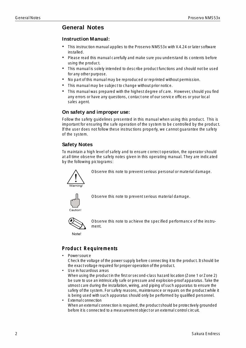
General Notes
Instruction Manual:
• This instruction manual applies to the Proservo NMS53x with V.4.24 or later softwareinstalled.
• Please read this manual carefully and make sure you understand its contents beforeusing the product.
• This manual is solely intended to describe product functions and should not be usedfor any other purpose.
• No part of this manual may be reproduced or reprinted without permission.• This manual may be subject to change without prior notice.• This manual was prepared with the highest degree of care. However, should you find
any errors or have any questions, contact one of our service offices or your localsales agent.
On safety and improper use:Follow the safety guidelines presented in this manual when using this product. This isimportant for ensuring the safe operation of the system to be controlled by the product.If the user does not follow these instructions properly, we cannot guarantee the safetyof the system.
Safety NotesTo maintain a high level of safety and to ensure correct operation, the operator shouldat all time observe the safety notes given in this operating manual. They are indicatedby the following pictograms:
Observe this note to prevent serious personal or material damage.
Observe this note to prevent serious material damage.
Observe this note to achieve the specified performance of the instru-ment.
Product RequirementsProduct RequirementsProduct RequirementsProduct RequirementsProduct Requirements• Power source
Check the voltage of the power supply before connecting it to the product. It should bethe exact voltage required for proper operation of the product.
• Use in hazardous areasWhen using the product in the first or second-class hazard location (Zone 1 or Zone 2)be sure to use an intrinsically safe or pressure and explosion-proof apparatus. Take theutmost care during the installation, wiring, and piping of such apparatus to ensure thesafety of the system. For safety reasons, maintenance or repairs on the product while itis being used with such apparatus should only be performed by qualified personnel.
• External connectionWhen an external connection is required, the product should be protectively groundedbefore it is connected to a measurement object or an external control circuit.
General Notes
Sakura Endress 3
Proservo NMS53x
1. Safety Instructions
Warning!Observe the following notes to prevent serious physical or material damage.
Power supply• Check that voltage and frequency of the local power supply are in the range of the
technical data of the instrument before turning on the power. Please refer to Sect.7.
Power supply cable• Use the power supply cable attached to the instrument when it is ordered from the
manufacturer, or the cable specified in the instruction.• The power source should have a ground terminal, and the power supply cable
should have a ground line. Please refer to Sect.7.
Grounding• Do not remove the grounding of the instrument when the power supply is turned on.
This may set the instrument in a dangerous condition. Please refer to Sect.7.
Wiring• Make sure the grounding of the instrument before connecting input and output to
another system.
Use of the instrumentThe Proservo NMS53x series is designed for level measurement of a liquid in a storagetank or similar facilities.• It is possible to connect auxiliary instruments in the specification described in this
manual. However, the performance of the connected instruments is not guaranteed.Please refer to the instructions attached to the individual instruments when they areconnected.
• A hazardous situation may occur if the instrument is used for a purpose that is notdesigned for or any other improper ways. The instrument has the IEC class 1(ground terminal).
Use in explosion hazardous areas• Please use the explosion-proof type for measurement in explosion-hazardous areas.• Instruments used in explosion hazardous areas should be mounted and wired
according to the explosion-proof regulations.• Instruments mounted in explosion hazardous areas must not be opened when the
power supply is turned on.• Tighten the cable gland firmly.• The maintenance and repair of the instrument are limited to fulfill the explosion
proof regulations.
1. Safety Instructions
4 Sakura Endress
Proservo NMS53x
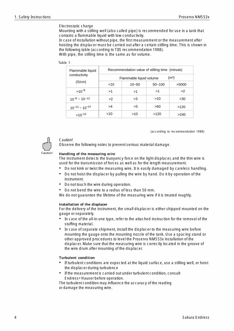
Electrostatic chargeMounting with a stilling well (also called pipe) is recommended for use in a tank thatcontains a flammable liquid with low conductivity.In case of installation without pipe, the first measurement or the measurement afterhoisting the displacer must be carried out after a certain stilling time. This is shown inthe following table (according to TIIS recommendation 1988).With pipe, the stilling time is the same as for volume.
Caution!Observe the following notes to prevent serious material damage.
Handling of the measuring wireThe instrument detects the buoyancy force on the light displacer, and the thin wire isused for the transmission of forces as well as for the length measurement.• Do not kink or twist the measuring wire. It is easily damaged by careless handling.• Do not hoist the displacer by pulling the wire by hand. Do it by operation of the
instrument.• Do not touch the wire during operation.• Do not bend the wire to a radius of less than 50 mm.We do not guarantee the lifetime of the measuring wire if it is treated roughly.
Installation of the displacerFor the delivery of the instrument, the small displacer is either shipped mounted on thegauge or separately.• In case of the all-in-one type, refer to the attached instruction for the removal of the
stuffing material.• In case of separate shipment, install the displacer to the measuring wire before
mounting the gauge onto the mounting nozzle of the tank. Use a spacing stand orother approved procedures to level the Proservo NMS53x installation of thedisplacer. Make sure that the measuring wire is correctly located in the groove ofthe wire drum after mounting of the displacer.
Turbulent condition• If turbulent conditions are expected at the liquid surface, use a stilling well, or hoist
the displacer during turbulence• If the measurement is carried out under turbulent condition, consult
Endress+Hauser before operation.The turbulent condition may influence the accuracy of the readingor damage the measuring wire.
1. Safety Instructions
Table 1
(according to recommendation 1988)
Flammable liquidconductivity
Recommendation value of stilling time
Flammable liquid volume(S/cm)
(minute)
(m³)
<10 10~50 50~100 >5000
>10
-810 ~ 10 -12
-12 10 ~ 10-14
<10
-8
-14
>1 >1 >1 >2
>2 >3 >10 >30
>4
>10 >10 >120
>120>60>5
>240
Sakura Endress 5
Proservo NMS53x
Local
ProthermoNMT535/6/8
ProservoNMS53...
Power (AC &DC)
Power (AC)
TemperatureLevelBottom levelInterface levelDensity
PromonitorNRF560
HART
Proservo NMS53x Application
(Power issupplied byProservoNMS53...)
Analog Output : * Alarm * 4...20mA
Digital Output:* Serial pulse V1* Rackbus RS485* WM550* M/S* HART* Enraf BPM
R
Input : * Status input * Remote operation
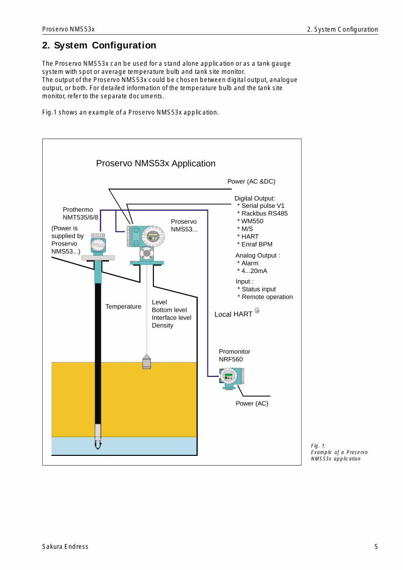
2. System Configuration
The Proservo NMS53x can be used for a stand alone application or as a tank gaugesystem with spot or average temperature bulb and tank site monitor.The output of the Proservo NMS53x could be chosen between digital output, analogueoutput, or both. For detailed information of the temperature bulb and the tank sitemonitor, refer to the separate documents.
Fig.1 shows an example of a Proservo NMS53x application.
Fig. 1:Example of a ProservoNMS53x application
2. System Configuration
6 Sakura Endress
Proservo NMS53x
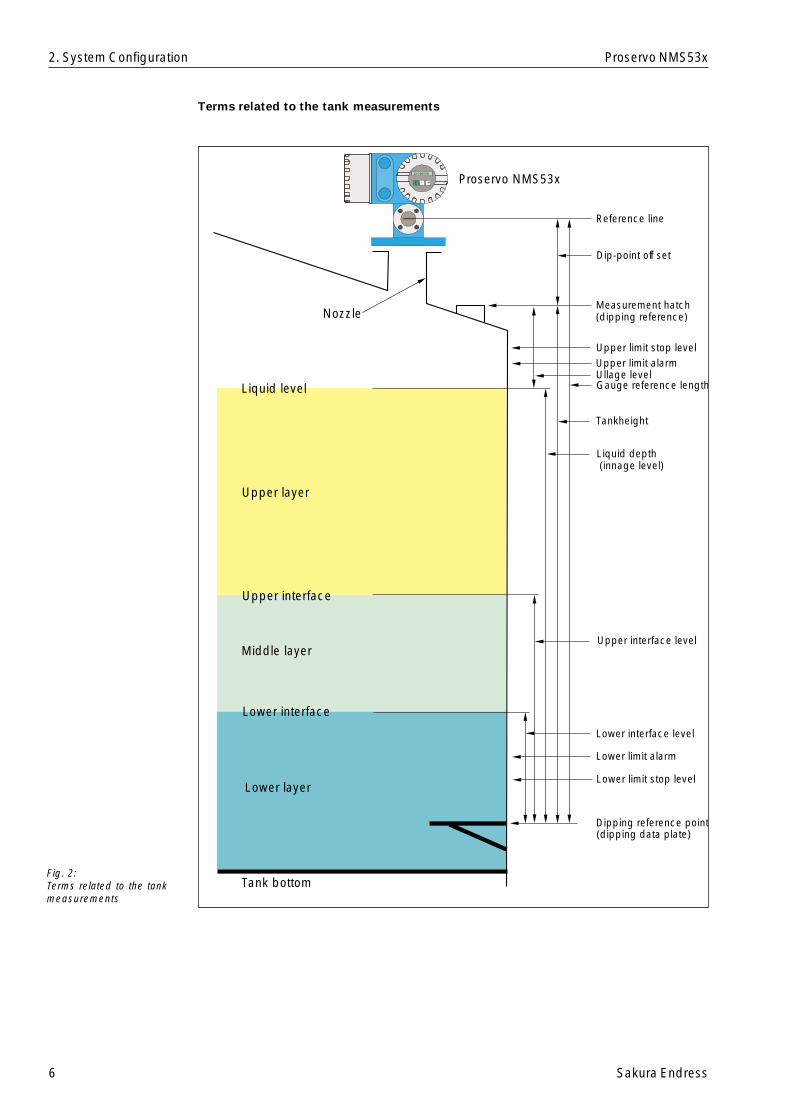
Fig. 2:Terms related to the tankmeasurements
Terms related to the tank measurements
2. System Configuration
Tank bottom
Lower layer
Middle layer
Upper layer
Upper interface
Lower interface
Liquid level
Nozzle
Proservo NMS53x
Reference line
Dip-point off set
Upper limit stop levelUpper limit alarmUllage levelGauge reference length
Tankheight
Upper interface level
Lower interface level
Lower limit alarm
Lower limit stop level
Dipping reference point
Liquid depth (innage level)
Measurement hatch(dipping reference)
(dipping data plate)
Sakura Endress 7
Proservo NMS53x
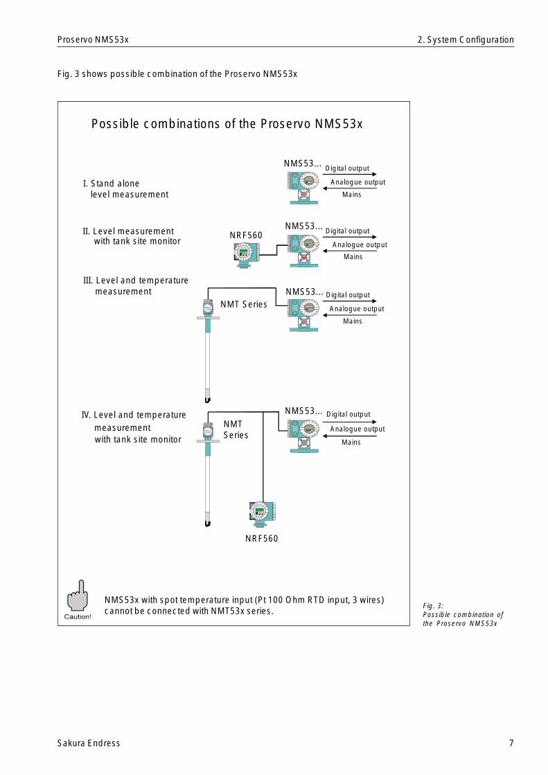
Fig. 3 shows possible combination of the Proservo NMS53x
NMS53x with spot temperature input (Pt 100 Ohm RTD input, 3 wires)cannot be connected with NMT53x series.
Fig. 3:Possible combination ofthe Proservo NMS53x
2. System Configuration
I. Stand alonelevel measurement
II. Level measurement with tank site monitor
III. Level and temperature measurement
IV. Level and temperature measurement with tank site monitor
NRF560
NMTSeries
NMT Series
NRF560
NMS53...
NMS53...
NMS53...
NMS53... Digital output
Digital output
Digital output
Digital output
Analogue output
Analogue output
Analogue output
Analogue output
Mains
Mains
Mains
Mains
Possible combinations of the Proservo NMS53x
8 Sakura Endress
Proservo NMS53x
3. Specifications and Dimensions
3.1 Typical Specifications
Measuring range: 0 to 10/16/28 m
Density limits: 0.5 to 2.0 g/ml
Self-diagnostic function: measuring wire tension, level data input, and communications,status, computer diagnostic, etc.
Liquid surface following speed: 0 to 2,500 mm/min.0 to 99 sec.
Display: Backlight LCD, 2 lines; 16 characters/line(indicating level and temperature at the same time)(Japanese/English, selectable)
Operation: Via touch control (touch-sensitive keys) or external contact input
Calibration: Automated (changes in displacer weight and wire stretchingautomatically compensated)
Compensation: Compensation for tank distortion
Parts maintenance and management Information: Load ratio calculated from the quantity of operation and operatingratio, then displayed and sent out as status information
Notepad function: Maintenance notepad
Accuracy: Liquid surface level: ±0.7 mm (density difference between twoliquids 0.2g/ml; displacer diameter 50mm; measuring range 10m)
Density: ±0.005 g/ml
Tank bottom: ±2.1 mm
Power requirements: high voltage type; 85 ... 264 V AC ,50/60 Hzlow voltage type; 20 ... 60 V DC / 20 ... 55 V AC 50/60 Hz
Consumption: Max. 50 VA, 20W (cos j=0.5)
Lightning arrestor: Standard equipment
Temperature limits: -20 to +60 deg. C(environmental temperature)
Liquid-arrestor: -200 to +200 deg. C
Weight: NMS531/534: 12 kgNMS532/536: 27 kg
Protection class: Ex d IIB T4, (TIIS)EEx d IIB T6, (PTB CENELEC)EEx d IIB T6 Zone0, (PTB CENELEC)XP Class1, Div.1, Gp.CD, (FM)Class1, Div.1, Gp.CD, (CSA)..Ex dEEx d[ia] IIB T6, (ATEX)EEx d[ia] IIB T6 Zone0, (ATEX)XP-AIS Class1, Div.1, Gp.CD, (FM)
Weights & Measures requirements approval: PTB (Germany), NMi (Netherlands)
Liquid leakage alarm requirements approval: TÜV Over Spill Protection (Germany)
Paint color: Body: light blue; Covers: lightgrey
Input/Output: External output: 4 to 20 mA, 4 contact outputs, Bi-directional digital pulse two-wire transmission , Rackbus RS485, Whessoe Matic 550, Mark/Space, HART, or Enraf Bi Phase Mark HARTExternal input/output: Local HART, NMT& NRF, Status input
Remote operation
Model name decoded
Operating pressure1. Atmospheric pressure (0.2 g/cm2: Aluminium casting)2. Atmospheric pressure (0.2 g/cm2: Stainless steel)4. Middle pressure (6 kg/cm2: Aluminium casting)5. Middle pressure (6 kg/cm2: Stainless steel)6. High pressure (25 kg/cm2: Stainless steel)7. Sanitary version (Stainless steel)
NMS-53
3. Specification and Dimensions
Sakura Endress 9
Proservo NMS53x
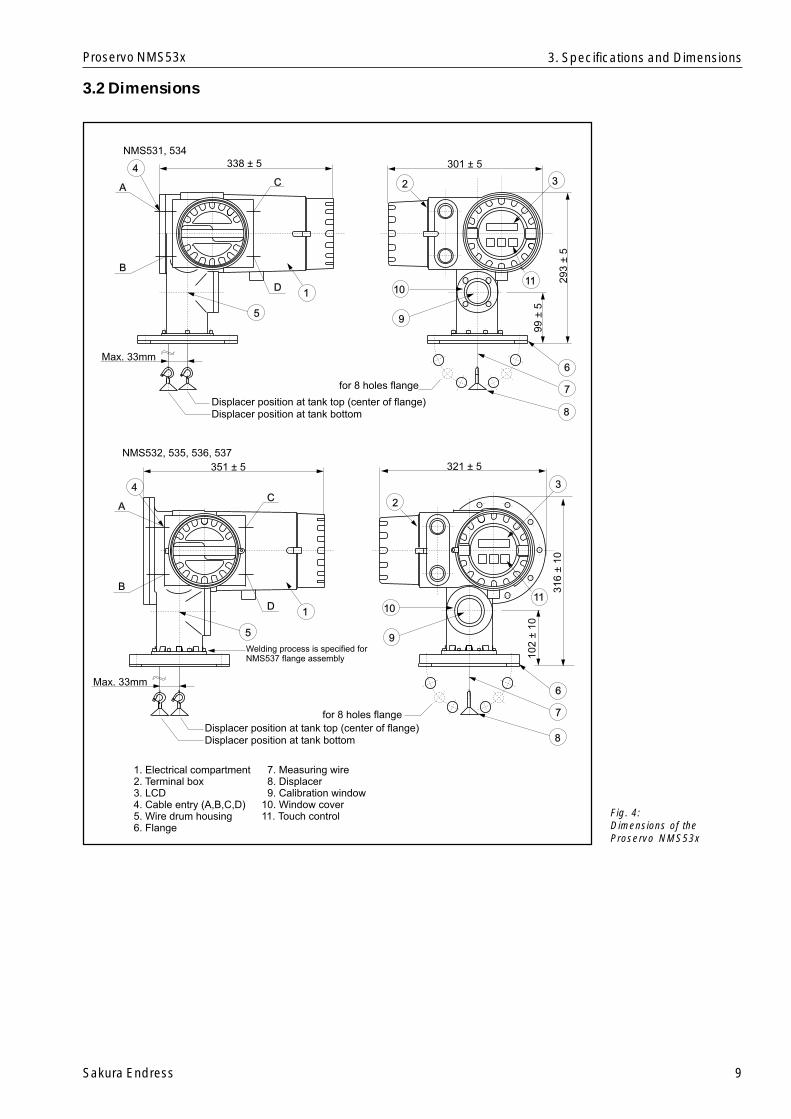
3.2 Dimensions
1. Electrical compartment2. Terminal box3. LCD4. Cable entry (A,B,C,D)5. Wire drum housing6. Flange
7. Measuring wire8. Displacer9. Calibration window
10. Window cover11. Touch control
Max. 33mm
338 ± 5 301 ± 5
293
±5
99
±5
A
B
C
D
4
5
1
for 8 holes flange
6
7
8
1110
9
2 3
Displacer position at tank top (center of flange)Displacer position at tank bottom
NMS531, 534
NMS532, 535, 536, 537
8
Max. 33mm6
7
11
3
for 8 holes flange
10
9
2A
B
C
D
4
5
1
351 ± 5 321 ± 5
316
±10
102
±10
Displacer position at tank top (center of flange)Displacer position at tank bottom
Welding process is specified forNMS537 flange assembly
Fig. 4:Dimensions of theProservo NMS53x
3. Specifications and Dimensions

10 Sakura Endress
Proservo NMS53x
4. Necessary Tools for Installation
You will need the following tools when installing the Proservo NMS53x.
4. Necessary Tools for Installation
* Tools are needed in calibration work for density and interface functions
Box wrench
Crescent wrench
Allen wrench
Screw driver
Wire Cutters / Terminal pliers
Wire terminal
50gweight
Sliding tray
Wire / hook
Screw*
*
*
*
Waterpumppliers
mm
mm
mm
mmB
24,26,30,32
350
3
3
1.25 , 2.0
flat head Philips
Sakura Endress 11
Proservo NMS53x
5. MountingThe following installation procedures are available for the Proservo NMS53x.• Mounting without guide system.• Mounting with stilling well (also called pipe)• Mounting with guide wire
5.1 Application drawing for tanksMounting with stilling well or guide wire is required for the following applications:• Floating roof tank• Covered floating roof tank• Tank with strong agitator or heavy turbulenceMounting without any guide system covers all cases that are not listed above.Fig. 5 shows examples of applications with and without stilling well.
Fig. 5:Application for each tank
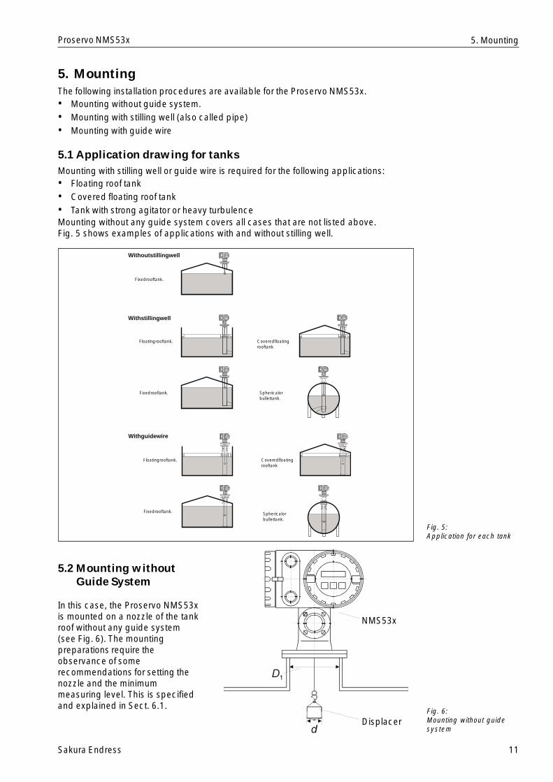
5.2 Mounting withoutGuide System
In this case, the Proservo NMS53xis mounted on a nozzle of the tankroof without any guide system(see Fig. 6). The mountingpreparations require theobservance of somerecommendations for setting thenozzle and the minimummeasuring level. This is specifiedand explained in Sect. 6.1.
Fig. 6:Mounting without guidesystem
5. Mounting
Displacer
NMS53x
Floatingrooftank.
Fixedrooftank.
Withoutstillingwell
Fixedrooftank.
Withstillingwell
Coveredfloatingrooftank
Sphericalorbullettank.
Withguidewire
Floatingrooftank.
Fixedrooftank.
Coveredfloatingrooftank
Sphericalorbullettank.

12 Sakura Endress
Proservo NMS53x
5.3 Mounting with Stilling WellPipe diameterThe pipe diameter that is required to protect the measuring wire without disturbing itsoperation depends on the tank height. The pipe could either be constant diameter, orthinner at its upper part and thicker at its lower part. Fig. 7 shows two examples ofthe latter case, namely an asymmetric pipe and a concentric pipe.
• This valve is necessary when mounting the Proservo NMS53x onto pressurizedliquid tanks.
• The Proservo NMS53x must be mounted on the asymmetric pipe in the directionshown above.
Fig. 7:Mounting with stilling well:Asymmetric pipe andconnection pipe
5. Mounting
ValveValve
Asymmetricpipe
Concentricpipe
Displacer Displacer
ProservoNMS53...
ProservoNMS53...
Asymmetric pipe (Side view) Concentric pipe (Front view)

Sakura Endress 13
Proservo NMS53x
D2 Inner diameter of the lower part of the pipe
L Length of the pipe (from the flange of the Proservo NMS53x to bottom of thestilling well) ...meters
v Deviation of the pipe from the vertical per length
d Diameter of the displacer
e Lateral shift of the displacer per length due to the groove of the wire drum(max.33 mm)
• Upper diameter
D1 > d + 10 mm
where D1 > 3" should be fulfilled.
• Lower diameter
- Asymmetric pipe
D2 > d+ eL + 2vL+ 10mm
- concentric pipe
D2 > d + 2eL + 2vL + 10mm
Recommendations for mountingRecommendations for mountingRecommendations for mountingRecommendations for mountingRecommendations for mountingNote!Observe the following recommendations for mounting with stilling well:• Keep the pipe connection welds smooth.• While drilling holes into the pipe, keep the interior surface of the holes clear of metal
chips and burrs.• Coat or paint the interior surface of the pipe to avoid rust.• Keep the pipe as perfectly vertical as possible. Check this by a plumb.• Install the asymmetric pipe under the valve and fit the centers of the Proservo and
the valve.• Set the center of the lower part of the asymmetric pipe to the direction of the
displacer motion.
5. Mounting
To calculate the required pipe diameters, the formulae below should be used.The variables and constants have the following meanings:
D1 Inner diameter of the upper part of the pipe

14 Sakura Endress
Proservo NMS53x
5.4 Mounting with Guide WireIt is also possible to guide the displacer by a guide wire to prevent lateralmotion. Fig. 8 shows this type of mounting.
Fig. 8:Mounting with guide wire
5. Mounting
Upper plate
ProservoNMS53...
Chamber for maintenance
Displacer100 mm
Wire hook Anchor weight

Sakura Endress 15
Proservo NMS53x
6. Mounting Preparations
6.1 FlangeThe mounting flange should be prepared before mounting the Proservo NMS53x to thetank. The flange size and the rating of the Proservo NMS53x depend on the customers’specifications. However, the standard size of the flange is 3".
Warning!Before pouring liquid into the tank, make sure that the flow from the inlet pipe cannothit the displacer directly.During discharging the tank, avoid suction of the displacer to the outlet pipe.
Note!• Check the flange size which is on the
surface of the Proservo NMS53x• Install the flange on the top of the
tank. Its deviation from the horizontalplane should not exceed +/- 1 deg(see Fig.9).
• For mounting the Proservo NMS53xonto a longer nozzle, make sure thatthe displacer does not touch theinterior surface because of thevertical inclination of the nozzle.
Note!If the Proservo is installed without guidesystem, then consider the followingrecommendations (see Fig. 10):• Set the mounting nozzle in the sector
between 45 and 90 deg (or -45 and-90 deg.) apart from the inlet pipe ofthe tank. This will prevent heavyswing of the displacer caused bywave or turbulence of the inlet liquid.
• Set the mounting nozzle at least500mm away from the tank wall. Thiswill ensure that the measurement isnot influenced by changes of theambient temperature.
• Set the minimum measuring level atleast 500mm above the top of theinlet pipe. This will protect thedisplacer from direct flow of the inletliquid.
If it is not possible to install the ProservoNMS53x in such place, then werecommend mounting with guidesystem. Consult E+H Service for furtherinformation.
Fig. 9:Allowable inclination ofthe mounting flange
Fig. 10:Recommended setting ofmounting nozzle andminimum measuring level
6. Mounting Preparations
Mounting nozzlemax. +1˚max. -1˚
-90˚ 90˚
-45˚ 45˚
0˚
Inletpipe
Mountingnozzle
Mountingnozzle
≥ 500 mm
Minimum measuring level
≥ 500 mmInletpipe

16 Sakura Endress
Proservo NMS53x
6.2 Electrostatic Charge
Note!• If the liquid measured by the Proservo NMS53x has a conductivity of less than 10-8
S/cm, it is quasi-nonconductive. In that case, we recommend to use a stilling well orguide wire made of conductive material. This will release the electrostatic charge onthe liquid surface.
• Without stilling well and guide wire, a certain stilling time must be kept before thedisplacer touches the liquid surface (see Sect. 1).
6. Mounting Preparations
Sakura Endress 17
Proservo NMS53x
7. Cable Connection
The electrical connection of the Proservo NMS53x is shown in Figs. 11 - 16.
Note!The power supply cable should have the following specifications:• PVC, PE, or equivalently isolated• 600 V insulation voltage or equivalent.The size of the core will be defined by core resistance, voltage drop, and requiredpower consumption. The maximum power consumption of the Proservo NMS53x is 50VA.
Caution!• Connect the ground line to the ground terminal inside or outside the terminal box.
7. Cable Connection
18 Sakura Endress
Proservo NMS53x
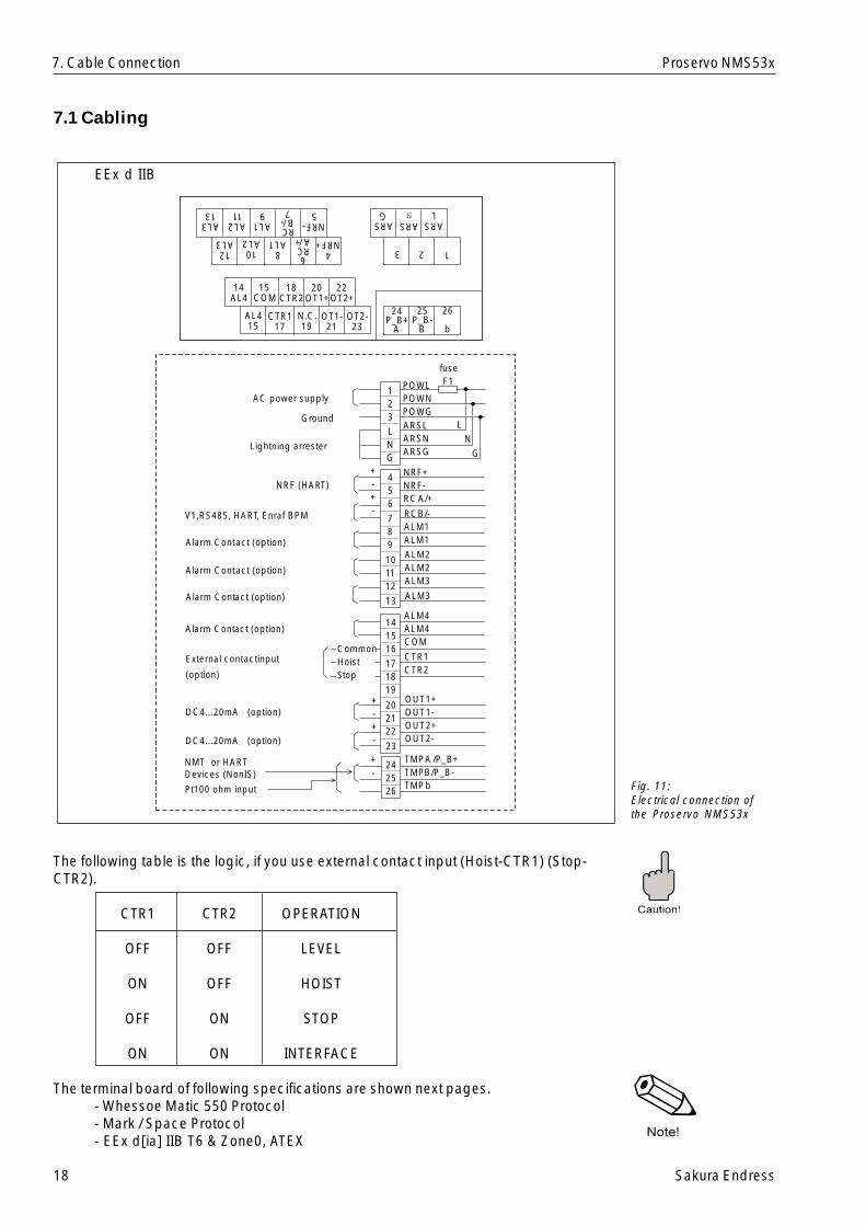
7.1 Cabling
The following table is the logic, if you use external contact input (Hoist-CTR1) (Stop-CTR2).
CTR1 CTR2 OPERATION
OFF OFF LEVEL
ON OFF HOIST
OFF ON STOP
ON ON INTERFACE
The terminal board of following specifications are shown next pages.- Whessoe Matic 550 Protocol- Mark / Space Protocol- EEx d[ia] IIB T6 & Zone0, ATEX
EEx d IIB
Fig. 11:Electrical connection ofthe Proservo NMS53x
7. Cable Connection
14AL4
15COM
18CTR2
20OT1+
22OT2+
AL415
CTR117
N.C.19
OT1-21
OT2-23
4NRF+
8AL1
10AL2
12AL3
AL313
AL211
AL19
RCB/-7
NRF-5
6RCA/+
24P_B+
A
25P_B-
B
26
b
123
ARSL
ARSG
ARS
POWLPOWNPOWGARSLARSNARSG
NRF+NRF-RCA/+
RCB/-ALM1ALM1
ALM2ALM2ALM3
123LNG
AC power supply
242526
+-
+-+-
ALM3
141516
171819
202122
+-+-
23
456
789
101112
13ALM4ALM4COM
CTR1CTR2
OUT1+OUT1-OUT2+OUT2-
TMPA/P_B+TMPB/P_B-TMPb
fuseF1
LN
GLightning arrester
NRF (HART)
V1,RS485, HAR T, Enraf BPM
Alarm Contact (option)
Alarm Contact (option)
Alarm Contact (option)
External contactinput
(option)
Alarm Contact (option)
DC4...20mA (option)
DC4...20mA (option)
NMT or HARTDevices (NonIS)
CommonHoistStop
Ground
Pt100 ohm input
N
Sakura Endress 19
Proservo NMS53x
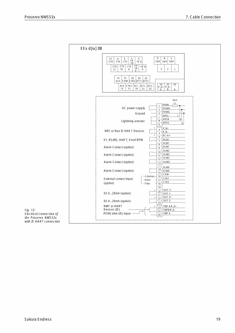
EEx d[ia] IIB
Fig. 12:Electrical connection ofthe Proservo NMS53xwith IS HART connection
7. Cable Connection
14AL4
15COM
18CTR2
20OT1+
22OT2+
AL415
CTR117
N.C.19
OT1-21
OT2-23
4P_B+
8AL1
10AL2
12AL3
AL313
AL211
AL19
RCB/-7
P_B-5
6RCA/+
24P_A+
A
25P_A-
B
26
b
123
ARSL
ARSG
ARSN
POWL
POWN
POWG
ARSL
ARSN
ARSG
P_B+
P_B-
RC A/+
RCB/-
ALM1
ALM1
ALM2
ALM2
ALM3
1
2
3
L
N
G
AC power supply
24
25
26
+
-
+
-
+
-
ALM3
14
15
16
17
18
19
20
21
22
+
-
+
-23
4
5
6
7
8
9
10
11
12
13
ALM4
ALM4
COM
CTR1
CTR2
OUT 1+
OUT 1-
OUT 2+
OUT 2-
TMP A/P_A+
TMPB/P_A-
TMP b
fuse
F1
L
N
GLightning arrester
NRF or Non IS HAR T Devices
V1, RS485, HAR T, Enraf BPM
Alarm Contact (option)
Alarm Contact (option)
Alarm Contact (option)
External contact input(option)
Alarm Contact (option)
DC4...20mA (option)
DC4...20mA (option)
Common
Hoist
Stop
Ground
NMT or HARTDevices (IS)Pt100 ohm (IS) input

20 Sakura Endress
Proservo NMS53x
Whessoe Matic 550 (WM550) Protocol with Non-IS Certificates
Fig. 13:Electrical connection ofthe Proservo NMS53xwith WM550 Protocol withNon-IS HART connection
7. Cable Connection
14AL4
15COM
18CTR2
20Ch1+
22Oh2+
AL415
CTR117
N.C.19
Ch1-21
Oh2-23
4NRF+
8AL1
10AL2
12AL3
AL313
AL211
AL19 7
NRF-5
6
24P_B+
A
25P_B-
B
26
b
123
ARSL
ARSG
ARSN
POWL
POWN
POWG
ARSL
ARSN
ARSG
NRF+
NRF-
ALM1
ALM1
ALM2
ALM2
ALM3
1
2
3
L
N
G
ACpower supply
24
25
26
+
-
+
-
+
-
ALM3
14
15
16
17
18
19
20
21
22
+
-
+
-23
4
5
6
7
8
9
10
11
12
13
ALM4
ALM4
COM
CTR1
CTR2
Ch1+
Ch1-
Ch2+
Ch2-
TMP A /P_B+
TMPB/P_B-
TMP b
fuse
F1
L
N
GLightning arrester
NRF (HAR T)
Alarm Contact (option)
Alarm Contact (option)
Alarm Contact (option)
External contact input(option)
Alarm Contact (option)
Whessoe Matic 550Channel 1
Whessoe Matic 550Channel 2
Common
Hoist
Stop
Ground
Pt100 ohm input
NMT or HARTDevices (Non IS)
Sakura Endress 21
Proservo NMS53x
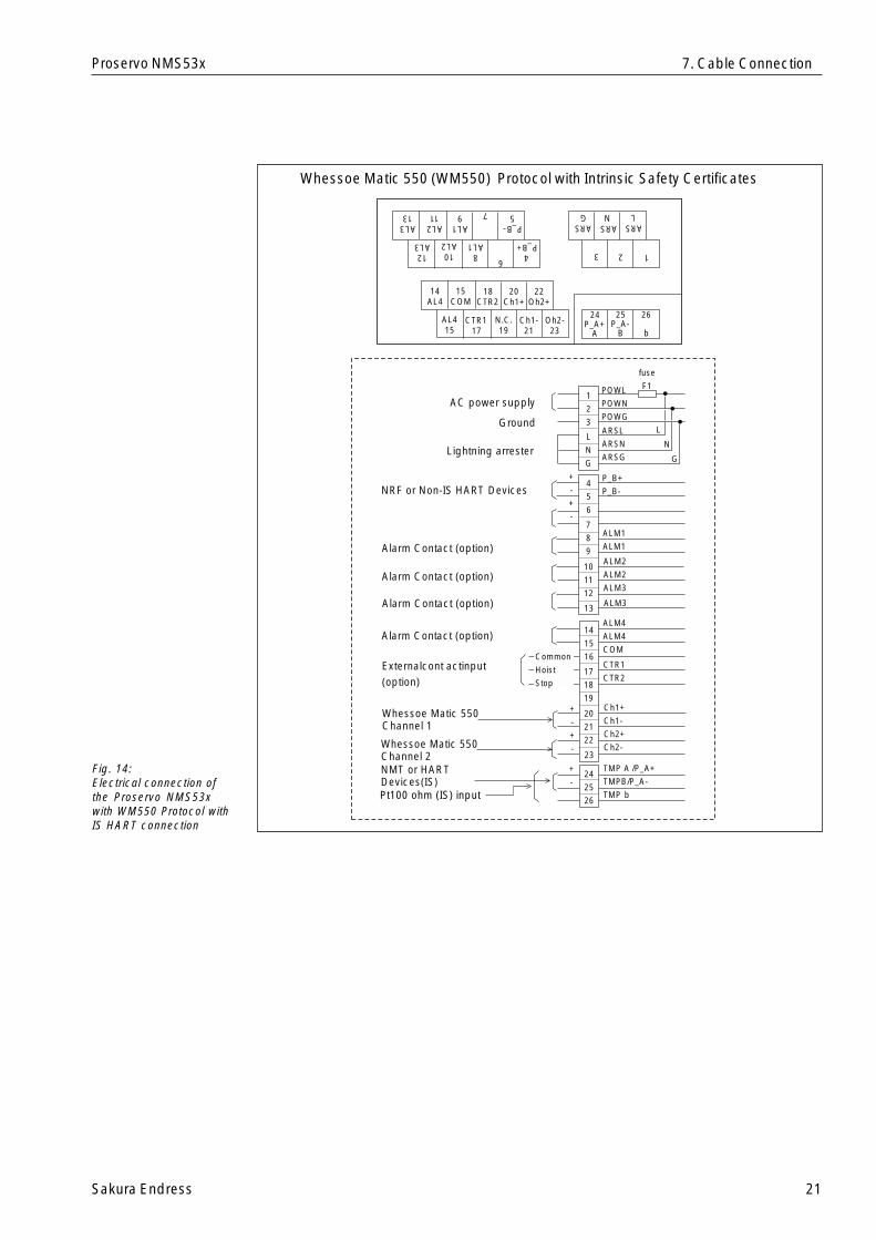
Whessoe Matic 550 (WM550) Protocol with Intrinsic Safety Certificates
Fig. 14:Electrical connection ofthe Proservo NMS53xwith WM550 Protocol withIS HART connection
7. Cable Connection
14AL4
15COM
18CTR2
20Ch1+
22Oh2+
AL415
CTR117
N.C.19
Ch1-21
Oh2-23
4P_B+
8AL1
10AL2
12AL3
AL313
AL211
AL19 7
P_B-5
6
24P_A+
A
25P_A-
B
26
b
123
ARSL
ARSG
ARSN
POWL
POWN
POWG
ARSL
ARSN
ARSG
P_B+
P_B-
ALM1
ALM1
ALM2
ALM2
ALM3
1
2
3
L
N
G
AC power supply
24
25
26
+
-
+
-
+
-
ALM3
14
15
16
17
18
19
20
21
22
+
-
+
-23
4
5
6
7
8
9
10
11
12
13
ALM4
ALM4
COM
CTR1
CTR2
Ch1+
Ch1-
Ch2+
Ch2-
TMP A /P_A+
TMPB/P_A-
TMP b
fuse
F1
L
N
GLightning arrester
Alarm Contact (option)
Alarm Contact (option)
Alarm Contact (option)
Externalcont actinput(option)
Alarm Contact (option)
Whessoe Matic 550Channel 1
Whessoe Matic 550Channel 2
Common
Hoist
Stop
Ground
NMT or HARTDevices(IS)
NRF or Non-IS HART Devices
Pt100 ohm (IS) input
22 Sakura Endress
Proservo NMS53x
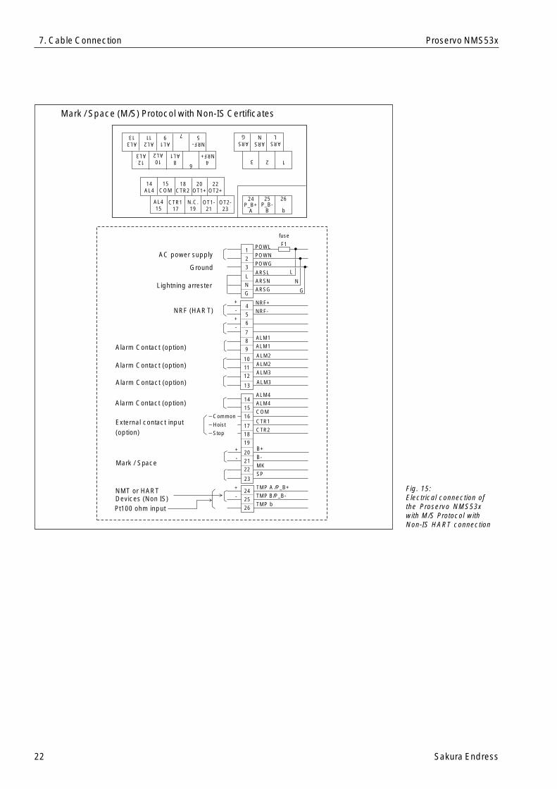
Mark / Space (M/S) Protocol with Non-IS Certificates
Fig. 15:Electrical connection ofthe Proservo NMS53xwith M/S Protocol withNon-IS HART connection
7. Cable Connection
14AL4
15COM
18CTR2
20OT1+
22OT2+
AL415
CTR117
N.C.19
OT1-21
OT2-23
4NRF+
8AL1
10AL2
12AL3
AL313
AL211
AL19 7
NRF-5
6
24P_B+
A
25P_B-
B
26
b
123
ARSL
ARSG
ARSN
POWL
POWN
POWG
ARSL
ARSN
ARSG
NRF+
NRF-
ALM1
ALM1
ALM2
ALM2
ALM3
1
2
3
L
N
G
AC power supply
24
25
26
+
-
+
-
+
-
ALM3
14
15
16
17
18
19
20
21
22
+
-
23
4
5
6
7
8
9
10
11
12
13
ALM4
ALM4
COM
CTR1
CTR2
B+
B-
MK
SP
TMP A /P_B+
TMP B/P_B-
TMP b
fuse
F1
L
N
GLightning arrester
NRF (HAR T)
Alarm Contact (option)
Alarm Contact (option)
Alarm Contact (option)
External contact input(option)
Alarm Contact (option)
Common
Hoist
Stop
Ground
Pt100 ohm input
NMT or HARTDevices (Non IS)
Mark / Space
Sakura Endress 23
Proservo NMS53x
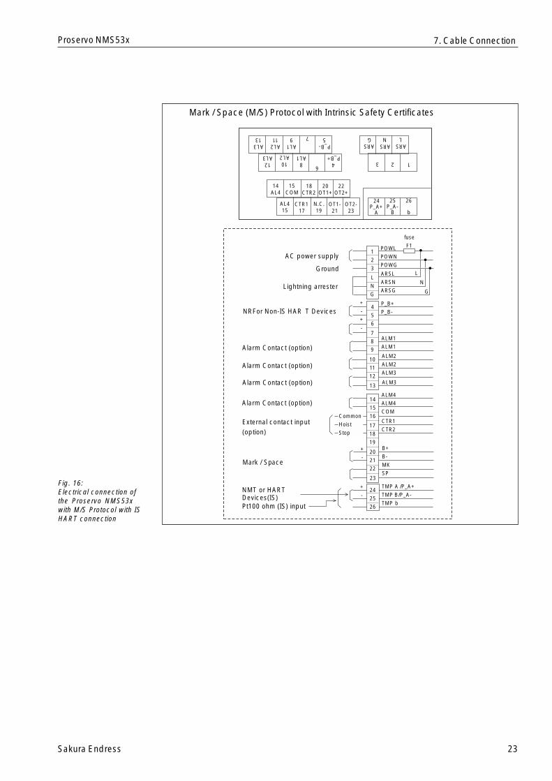
Mark / Space (M/S) Protocol with Intrinsic Safety Certificates
Fig. 16:Electrical connection ofthe Proservo NMS53xwith M/S Protocol with ISHART connection
7. Cable Connection
14AL4
15COM
18CTR2
20OT1+
22OT2+
AL415
CTR117
N.C.19
OT1-21
OT2-23
4P_B+
8AL1
10AL2
12AL3
AL313
AL211
AL19 7
P_B-5
6
24P_A+
A
25P_A-
B
26
b
123
ARSL
ARSG
ARSN
POWL
POWN
POWG
ARSL
ARSN
ARSG
P_B+
P_B-
ALM1
ALM1
ALM2
ALM2
ALM3
1
2
3
L
N
G
AC power supply
24
25
26
+
-
+
-
+
-
ALM3
14
15
16
17
18
19
20
21
22
+
-
23
4
5
6
7
8
9
10
11
12
13
ALM4
ALM4
COM
CTR1
CTR2
B+
B-
MK
SP
TMP A /P_A+
TMP B/P_A-
TMP b
fuse
F1
L
N
GLightning arrester
NRFor Non-IS HAR T Devices
Alarm Contact (option)
Alarm Contact (option)
Alarm Contact (option)
External contact input(option)
Alarm Contact (option)
Common
Hoist
Stop
Ground
NMT or HARTDevices(IS)
Mark / Space
Pt100 ohm (IS) input
24 Sakura Endress
Proservo NMS53x
7.2 Input and output
• V1 serial bus is used for the connection of the existing receiving system of SakuraEndress or the tank farm where the distance from the tank site to the control room ismax. 6 km.
• RS 485 with Rackbus protocol is used for normal applications together with otherEndress+Hauser products.
• Alarm contacts and external contact input analogue signal are available as optionaloutput.
• A HART input is available where temperature sensor Prothermo NMT535/6/8, tanksite monitor Promonitor NRF560, or other HART devices can be connected.
• A Pt100 ohm RTD input is available as optional input.
Warning!The cable used for input and/or output must be more than 24 AWG screened or steelarmored. A twisted pair is required for the HART and/or RS 485 signal.
Two or three cores for mains, two cores for digital output, and two cores for HART inputare normally used for the cabling of the Proservo NMS53x. The instrument has max.four cable entries.
Before you place an order for the Proservo NMS53x, please check the cable size andthe number of cables.
7.3 Cable GlandIf you do not use all the cable entries, then take out unnecessary glands and put theplug to the thread to prevent intrusion of water.
7. Cable Connection
Sakura Endress 25
Proservo NMS53x
8. Displacer and Measuring Wire
8.1 Shape, Diameter, and Material
DisplacerThere are several types of displacer available for the Proservo NMS53x:• The standard type has cylindrical shape and a diameter of 50 mm. Diameters from
30 to 50 mm are optional (PTB Weights & Measures type is a diameter of 110 mm.NMi Weights & Weights type is a diameter of 70 mm)
• Cylindrical shape is used for sticky material. It is also effective if the stilling well hasa burr on its interior surface.
Displacer weight and volume depend on the application. Thin displacers are suited forlevel measurement, thicker ones for bottom level, interface level, and density measure-ment.A counterweight is optional for heavy turbulence.Displacers of three different materials are provided:• The standard material is stainless steel SUS316.• Hastelloy C and PTFE coated are optional for corrosive liquids.• Solid PTFE, however, is not applied for flammable liquids.
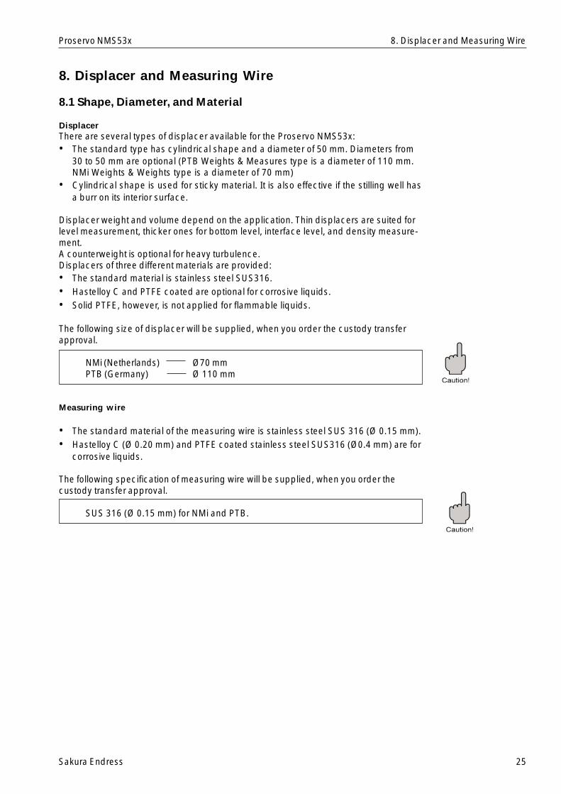
The following size of displacer will be supplied, when you order the custody transferapproval.
NMi (Netherlands) Ø70 mmPTB (Germany) Ø 110 mm
Measuring wire
• The standard material of the measuring wire is stainless steel SUS 316 (Ø 0.15 mm).• Hastelloy C (Ø 0.20 mm) and PTFE coated stainless steel SUS316 (Ø0.4 mm) are for
corrosive liquids.
The following specification of measuring wire will be supplied, when you order thecustody transfer approval.
SUS 316 (Ø 0.15 mm) for NMi and PTB.
8. Displacer and Measuring Wire
26 Sakura Endress
Proservo NMS53x
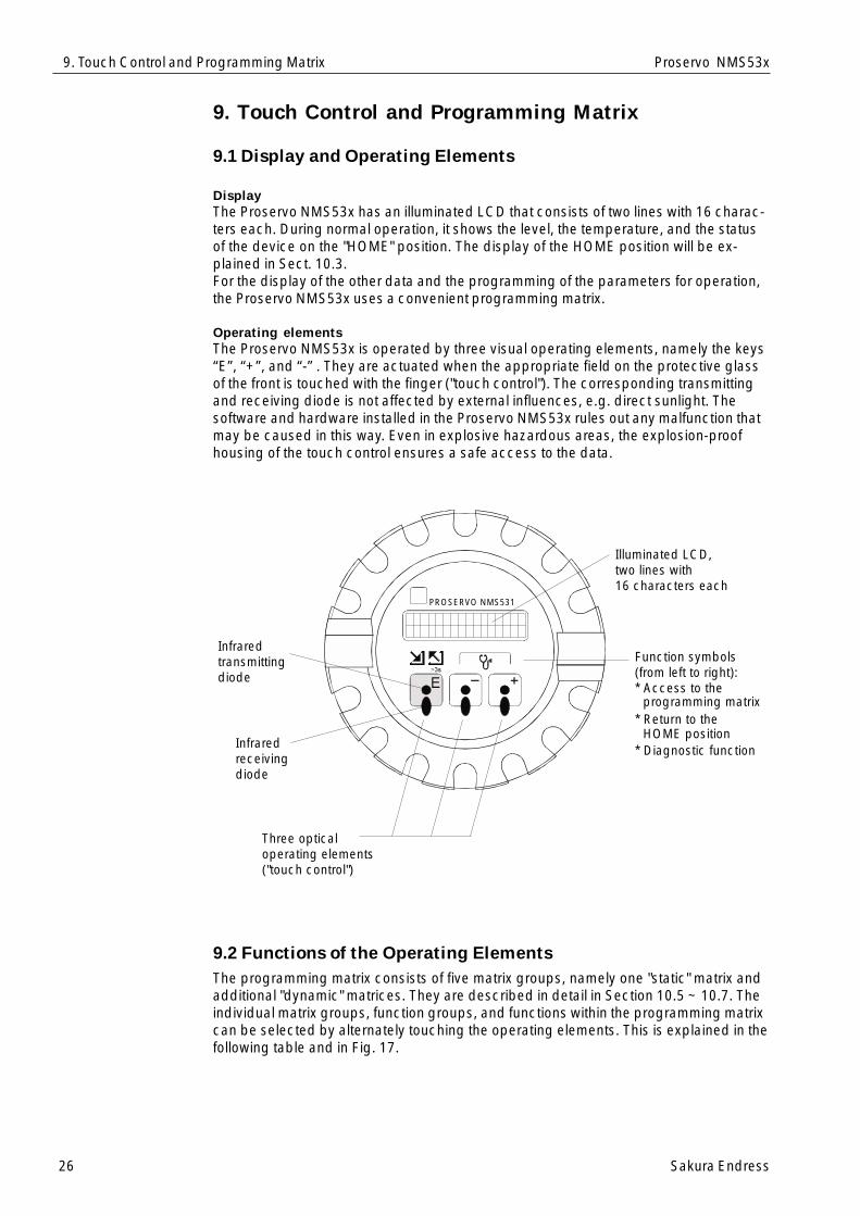
9. Touch Control and Programming Matrix
9.1 Display and Operating Elements
DisplayThe Proservo NMS53x has an illuminated LCD that consists of two lines with 16 charac-ters each. During normal operation, it shows the level, the temperature, and the statusof the device on the "HOME" position. The display of the HOME position will be ex-plained in Sect. 10.3.For the display of the other data and the programming of the parameters for operation,the Proservo NMS53x uses a convenient programming matrix.
Operating elementsThe Proservo NMS53x is operated by three visual operating elements, namely the keys“E”, “+”, and “-” . They are actuated when the appropriate field on the protective glassof the front is touched with the finger ("touch control"). The corresponding transmittingand receiving diode is not affected by external influences, e.g. direct sunlight. Thesoftware and hardware installed in the Proservo NMS53x rules out any malfunction thatmay be caused in this way. Even in explosive hazardous areas, the explosion-proofhousing of the touch control ensures a safe access to the data.
9.2 Functions of the Operating ElementsThe programming matrix consists of five matrix groups, namely one "static" matrix andadditional "dynamic" matrices. They are described in detail in Section 10.5 ~ 10.7. Theindividual matrix groups, function groups, and functions within the programming matrixcan be selected by alternately touching the operating elements. This is explained in thefollowing table and in Fig. 17.
9. Touch Control and Programming Matrix
Infraredtransmittingdiode
Infraredreceivingdiode
Three opticaloperating elements("touch control")
Illuminated LCD,two lines with16 characters each
Function symbols(from left to right):* Access to the
* Return to the
* Diagnostic function
programming matrix
HOME position
PROSERVO NMS531
Sakura Endress 27
Proservo NMS53x
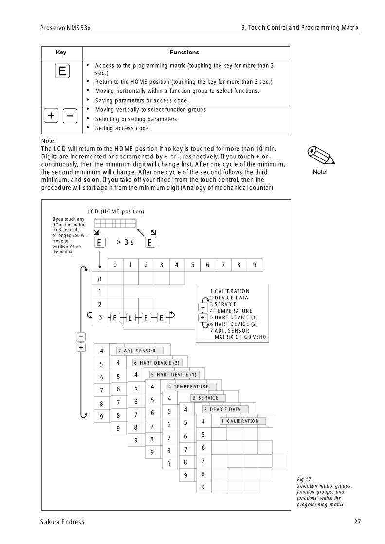
Key Functions
• Access to the programming matrix (touching the key for more than 3sec.)
• Return to the HOME position (touching the key for more than 3 sec.)
• Moving horizontally within a function group to select functions.
• Saving parameters or access code.
• Moving vertically to select function groups
• Selecting or setting parameters
• Setting access code
Note!The LCD will return to the HOME position if no key is touched for more than 10 min.Digits are incremented or decremented by + or -, respectively. If you touch + or -continuously, then the minimum digit will change first. After one cycle of the minimum,the second minimum will change. After one cycle of the second follows the thirdminimum, and so on. If you take off your finger from the touch control, then theprocedure will start again from the minimum digit (Analogy of mechanical counter)
9. Touch Control and Programming Matrix
Fig.17:Selection matrix groups,function groups, andfunctions within theprogramming matrix
LCD (HOME position)
1 CALIBRATION2 DEVICE DATA3 SERVICE4 TEMPERATURE5 HART DEVICE (1)6 HART DEVICE (2)7 ADJ. SENSOR MATRIX OF G0 V3H0
If you touch any"E" on the matrixfor 3 secondsor longer, you willmove to position V0 on the matrix.
E E
E E E E +
_
> 3 s
0 1 2 3 987654
0
1
2
3
4
5
6
9
8
7
4
4
4
4
4
4
5
5
5
5
5
5
6
6
6
6
6
6
7
7
7
7
7
7
8
8
8
8
8
8
9
9
9
9
9
9
7 ADJ. SENSOR
6 HART DEVICE (2)
5 HART DEVICE (1)
4 TEMPERATURE
3 SERVICE
2 DEVICE DATA
1 CALIBRATION
28 Sakura Endress
Proservo NMS53x9. Touch Control and Programming Matrix
9.3 HOME Position
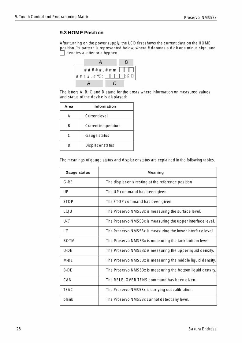
After turning on the power supply, the LCD first shows the current data on the HOMEposition. Its pattern is represented below, where # denotes a digit or a minus sign, and denotes a letter or a hyphen.
The letters A, B, C and D stand for the areas where information on measured valuesand status of the device is displayed:
Area Information
A Current level
B Current temperature
C Gauge status
D Displacer status
The meanings of gauge status and displacer status are explained in the following tables.
Gauge status Meaning
G-RE The displacer is resting at the reference position
UP The UP command has been given.
STOP The STOP command has been given.
LIQU The Proservo NMS53x is measuring the surface level.
U-IF The Proservo NMS53x is measuring the upper interface level.
LIF The Proservo NMS53x is measuring the lower interface level.
BOTM The Proservo NMS53x is measuring the tank bottom level.
U-DE The Proservo NMS53x is measuring the upper liquid density.
M-DE The Proservo NMS53x is measuring the middle liquid density.
B-DE The Proservo NMS53x is measuring the bottom liquid density.
CAN The RELE. OVER TENS command has been given.
TEAC The Proservo NMS53x is carrying out calibration.
blank The Proservo NMS53x cannot detect any level.
# # # # # . # mm
# # # # . # °C: : E �
A
B C
D

Sakura Endress 29
Proservo NMS53x
Displacer statusDisplacer statusDisplacer statusDisplacer statusDisplacer status MeaningMeaningMeaningMeaningMeaning
BAL The displacer is resting on the liquid surface or interface andin balanced status.
T-B Automatic weight calibration is being carried out.
U-U The displacer is being hoisted and in unbalanced status.
U-D The displacer is being lowered and in unbalanced status.
R-U The displacer is being hoisted and in correction of balance.
R-D The displacer is being lowered and in correction of balance.
LOW The displacer is resting at the lower stop.
Note!If no key is touched for more than 10 min., then the Proservo NMS53x will turn off thebacklighting of the LCD to save energy, touching a key again after this time will turn onthe backlighting.
9. Touch Control and Programming Matrix
30 Sakura Endress
Proservo NMS53x9. Touch Control and Programming Matrix
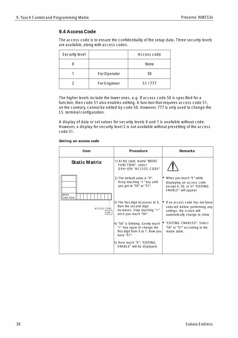
9.4 Access Code
The access code is to ensure the confidentiality of the setup data. Three security levelsare available, along with access codes.
Security level Access code
0 None
1 For Operator 50
2 For Engineer 51 / 777
The higher levels include the lower ones. e.g. If access code 50 is specified for afunction, then code 51 also enables editing. A function that requires access code 51,on the contrary, cannot be edited by code 50. However, 777 is only used to change theI.S. terminal configuration.
A display of data or set values for security levels 0 and 1 is available without code.However, a display for security level 2 is not available without presetting of the accesscode 51.
Setting an access code
Item Procedure Remarks
Static Matrix 1) At the static matrix “MOREFUNCTION”, selectGVH=039 “ACCESS CODE”
2) The default value is “0”.Keep touching “+” key untilyou get to “50” or “51”.
3) The first digit increases to 9,then the second digitincreases. Stop touching “+”once you reach “50”.
4) “50” is blinking. Gently touch“+” key again to change thefirst digit from 0 to 1. Now youhave “51”.
5) Here touch “E”; “EDITINGENABLE” will be displayed.
• When you touch “E” whiledisplaying an access codeexcept 0, 50, or 51 “EDITINGENABLE” will appear.
• If an access code has not beenselected before performing anysettings, the screen willautomatically change to show
• “EDITING ENABLED”. Select“50” or “51” according to thematrix table.
MOREFUNCTION
ACCESS CODE
039
Sakura Endress 31
Proservo NMS53x
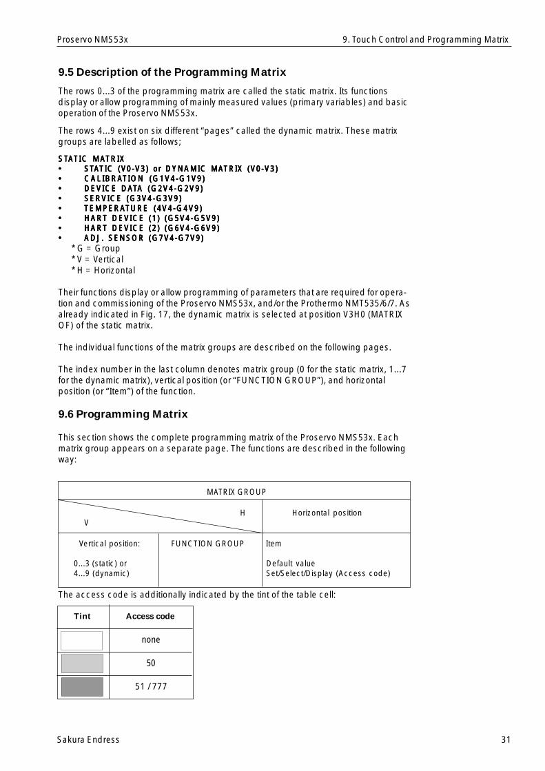
9.5 Description of the Programming Matrix
The rows 0...3 of the programming matrix are called the static matrix. Its functionsdisplay or allow programming of mainly measured values (primary variables) and basicoperation of the Proservo NMS53x.
The rows 4...9 exist on six different “pages” called the dynamic matrix. These matrixgroups are labelled as follows;
STSTSTSTSTAAAAATIC MATIC MATIC MATIC MATIC MATRIXTRIXTRIXTRIXTRIX••••• STSTSTSTSTAAAAATIC (V0-V3) or DYNAMIC MATIC (V0-V3) or DYNAMIC MATIC (V0-V3) or DYNAMIC MATIC (V0-V3) or DYNAMIC MATIC (V0-V3) or DYNAMIC MATRIX (V0-V3)TRIX (V0-V3)TRIX (V0-V3)TRIX (V0-V3)TRIX (V0-V3)••••• CALIBRACALIBRACALIBRACALIBRACALIBRATION (G1V4-G1V9)TION (G1V4-G1V9)TION (G1V4-G1V9)TION (G1V4-G1V9)TION (G1V4-G1V9)••••• DEVICE DADEVICE DADEVICE DADEVICE DADEVICE DATTTTTA (G2V4-G2V9)A (G2V4-G2V9)A (G2V4-G2V9)A (G2V4-G2V9)A (G2V4-G2V9)••••• SERVICE (G3V4-G3V9)SERVICE (G3V4-G3V9)SERVICE (G3V4-G3V9)SERVICE (G3V4-G3V9)SERVICE (G3V4-G3V9)••••• TEMPERATEMPERATEMPERATEMPERATEMPERATURE (4V4-G4V9)TURE (4V4-G4V9)TURE (4V4-G4V9)TURE (4V4-G4V9)TURE (4V4-G4V9)••••• HART DEVICE (1) (G5V4-G5V9)HART DEVICE (1) (G5V4-G5V9)HART DEVICE (1) (G5V4-G5V9)HART DEVICE (1) (G5V4-G5V9)HART DEVICE (1) (G5V4-G5V9)••••• HART DEVICE (2) (G6V4-G6V9)HART DEVICE (2) (G6V4-G6V9)HART DEVICE (2) (G6V4-G6V9)HART DEVICE (2) (G6V4-G6V9)HART DEVICE (2) (G6V4-G6V9)••••• ADJ. SENSOR (G7V4-G7V9)ADJ. SENSOR (G7V4-G7V9)ADJ. SENSOR (G7V4-G7V9)ADJ. SENSOR (G7V4-G7V9)ADJ. SENSOR (G7V4-G7V9)
* G = Group* V = Vertical* H = Horizontal
Their functions display or allow programming of parameters that are required for opera-tion and commissioning of the Proservo NMS53x, and/or the Prothermo NMT535/6/7. Asalready indicated in Fig. 17, the dynamic matrix is selected at position V3H0 (MATRIXOF) of the static matrix.
The individual functions of the matrix groups are described on the following pages.
The index number in the last column denotes matrix group (0 for the static matrix, 1...7for the dynamic matrix), vertical position (or “FUNCTION GROUP”), and horizontalposition (or “Item”) of the function.
9.6 Programming Matrix
This section shows the complete programming matrix of the Proservo NMS53x. Eachmatrix group appears on a separate page. The functions are described in the followingway:
MATRIX GROUP
H Horizontal positionV
Vertical position: FUNCTION GROUP Item
0...3 (static) or Default value4...9 (dynamic) Set/Select/Display (Access code)
The access code is additionally indicated by the tint of the table cell:
Tint Access code
9. Touch Control and Programming Matrix
none
50
51 / 777
32S
akura End
ress
Proservo N
MS
53x10. Touch C
ontrol and P
rogram
ming
Matrix
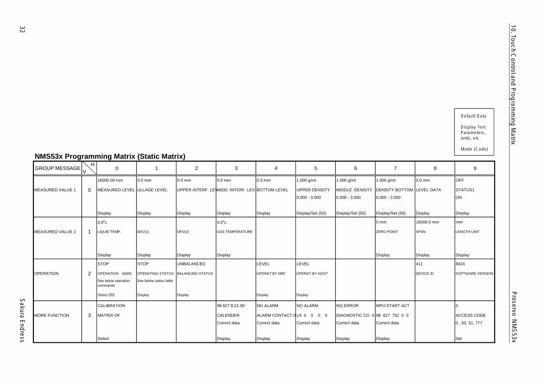
NMS53x Programming Matrix (Static Matrix)GROUP MESSAGE 0 1 2 3 4 5 6 7 8 9
16000.00 mm 0.0 mm 0.0 mm 0.0 mm 0.0 mm 1.000 g/ml 1.000 g/ml 1.000 g/ml 0.0 mm OFF
MEASURED VALUE 1 0 MEASURED LEVEL ULLAGE LEVEL UPPER INTERF. LEVMIDD. INTERF. LEV BOTTOM LEVEL UPPER DENSITY MIDDLE DENSITY DENSITY BOTTOM LEVEL DATA STATUS1
Display Display Display Display Display
0.000 - 3.000
Display/Set (50)
0.000 - 3.000
Display/Set (50)
0.000 - 3.000
Display/Set (50) Display
ON
Display
0.0oc 0.0oc 0 mm 16000.0 mm mm
MEASURED VALUE 2 1 LIQUID TEMP. DEV(1) DEV(2) GAS TEMPERATURE ZERO POINT SPAN LENGTH UNIT
Display Display Display Display Display Display Display
STOP STOP UNBALANCED LEVEL LEVEL 411 8424
OPERATION 2 OPERATION 16000 OPERATING STATUS BALANCING STATUS OPERAT.BY NRF OPERAT.BY HOST DEVICE ID SOFTWARE VERSION
See below operationcommands
Select (50)
See below status table
Display Display Display Display
CALIBRATION 98 627 8:21:00 NO ALARM NO ALARM NO ERROR MPU:START ACT 0
MORE FUNCTION 3 MATRIX OF CALENDER ALARM CONTACT 0 LA 0 0 0 0 DIAGNOSTIC CO 0 98 627 752 0 0 ACCESS CODE
Select
Currect data
Display
Currect data
Display
Currect data
Display
Currect data
Display
Currect data
Display
0 , 50, 51, 777
Set
VH
Default Data
Display TextParameters,units, etc.
Mode (Code)
Sakura E
ndress
33
Proservo N
MS
53x9. Touch C
ontrol and P
rogram
ming
Matrix
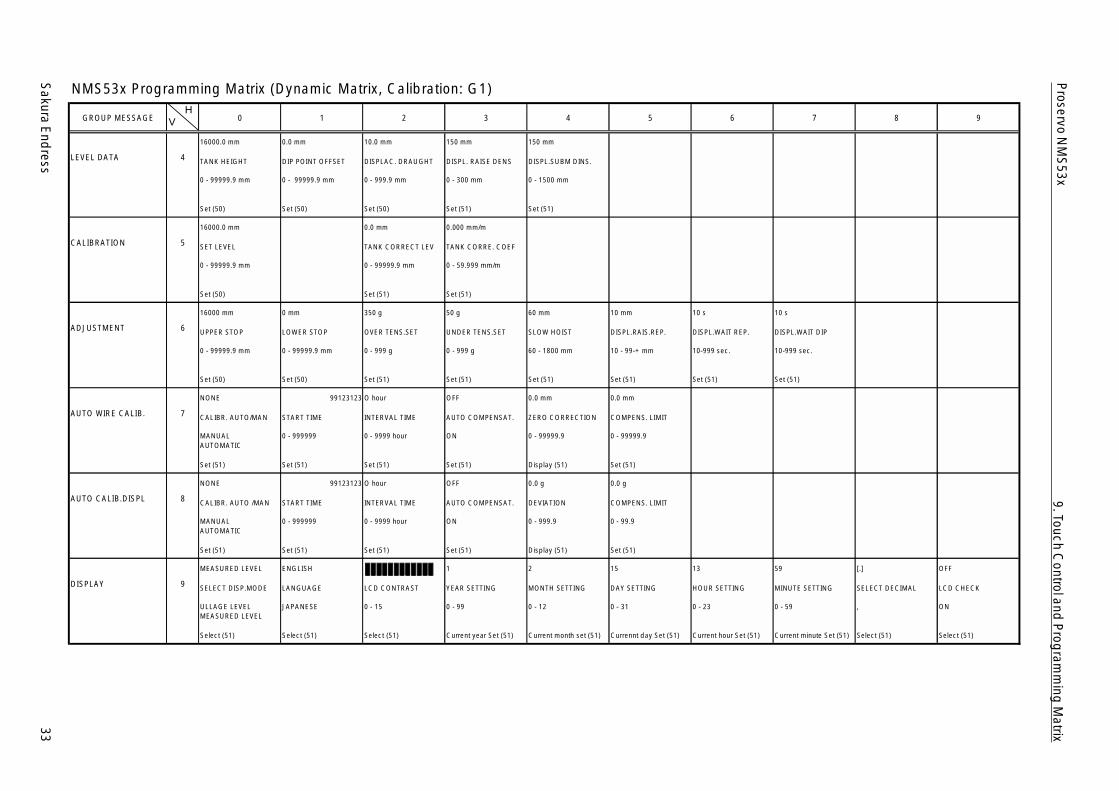
NMS53x Programming Matrix (Dynamic Matrix, Calibration: G1)
GROUP MESSAGE 0 1 2 3 4 5 6 7 8 9
16000.0 mm 0.0 mm 10.0 mm 150 mm 150 mm
LEVEL DATA 4 TANK HEIGHT DIP POINT OFFSET DISPLAC. DRAUGHT DISPL. RAISE DENS DISPL.SUBM DINS.
0 - 99999.9 mm
Set (50)
0 - 99999.9 mm
Set (50)
0 - 999.9 mm
Set (50)
0 - 300 mm
Set (51)
0 - 1500 mm
Set (51)
16000.0 mm 0.0 mm 0.000 mm/m
CALIBRATION 5 SET LEVEL TANK CORRECT LEV TANK CORRE. COEF
0 - 99999.9 mm
Set (50)
0 - 99999.9 mm
Set (51)
0 - 59.999 mm/m
Set (51)
16000 mm 0 mm 350 g 50 g 60 mm 10 mm 10 s 10 s
ADJUSTMENT 6 UPPER STOP LOWER STOP OVER TENS.SET UNDER TENS.SET SLOW HOIST DISPL.RAIS.REP. DISPL.WAIT REP. DISPL.WAIT DIP
0 - 99999.9 mm
Set (50)
0 - 99999.9 mm
Set (50)
0 - 999 g
Set (51)
0 - 999 g
Set (51)
60 - 1800 mm
Set (51)
10 - 99-+ mm
Set (51)
10-999 sec.
Set (51)
10-999 sec.
Set (51)
NONE 99123123 O hour OFF 0.0 mm 0.0 mm
AUTO WIRE CALIB. 7 CALIBR. AUTO/MAN START TIME INTERVAL TIME AUTO COMPENSAT. ZERO CORRECTION COMPENS. LIMIT
MANUALAUTOMATIC
Set (51)
0 - 999999
Set (51)
0 - 9999 hour
Set (51)
ON
Set (51)
0 - 99999.9
Display (51)
0 - 99999.9
Set (51)
NONE 99123123 O hour OFF 0.0 g 0.0 g
AUTO CALIB.DISPL 8 CALIBR. AUTO /MAN START TIME INTERVAL TIME AUTO COMPENSAT. DEVIATION COMPENS. LIMIT
MANUALAUTOMATIC
Set (51)
0 - 999999
Set (51)
0 - 9999 hour
Set (51)
ON
Set (51)
0 - 999.9
Display (51)
0 - 99.9
Set (51)
MEASURED LEVEL ENGLISH 1 2 15 13 59 [.] OFF
DISPLAY 9 SELECT DISP.MODE LANGUAGE LCD CONTRAST YEAR SETTING MONTH SETTING DAY SETTING HOUR SETTING MINUTE SETTING SELECT DECIMAL LCD CHECK
ULLAGE LEVELMEASURED LEVEL
Select (51)
JAPANESE
Select (51)
0 - 15
Select (51)
0 - 99
Current year Set (51)
0 - 12
Current month set (51)
0 - 31
Currennt day Set (51)
0 - 23
Current hour Set (51)
0 - 59
Current minute Set (51)
,
Select (51)
ON
Select (51)
VH
34S
akura End
ress
Proservo N
MS
53x9. Touch C
ontrol and P
rogram
ming
Matrix
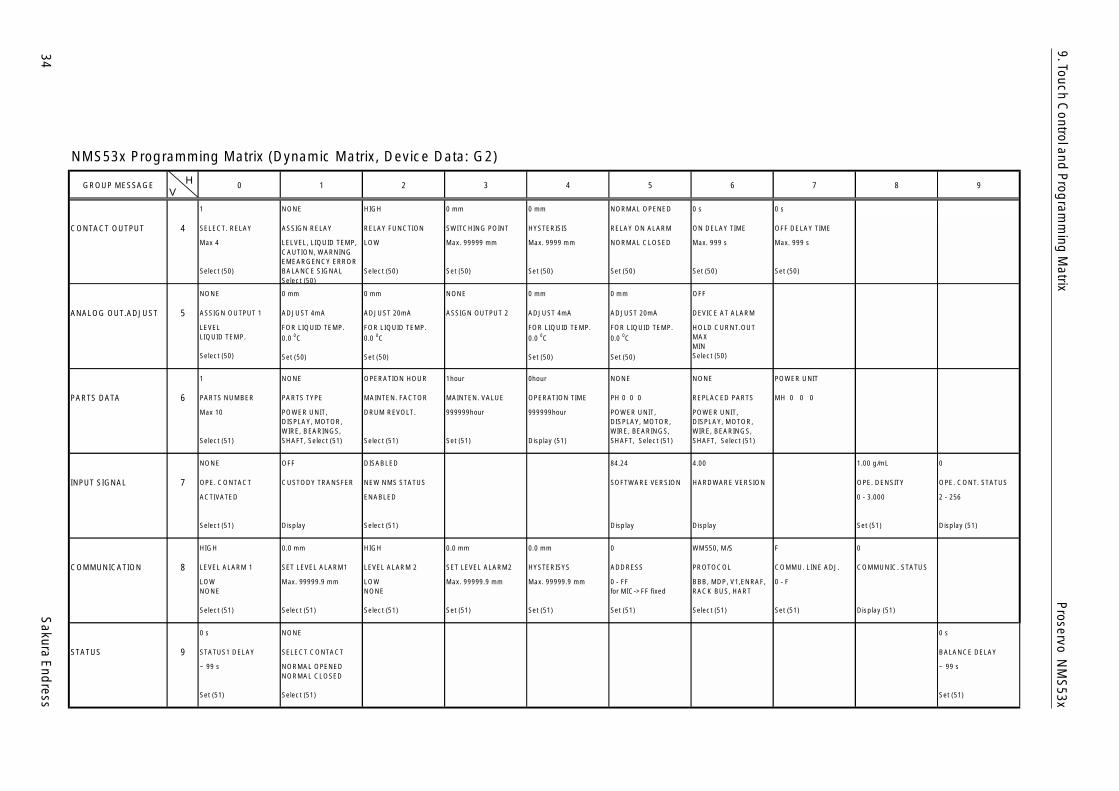
NMS53x Programming Matrix (Dynamic Matrix, Device Data: G2)
GROUP MESSAGE 0 1 2 3 4 5 6 7 8 9
1 NONE HIGH 0 mm 0 mm NORMAL OPENED 0 s 0 s
CONTACT OUTPUT 4 SELECT. RELAY ASSIGN RELAY RELAY FUNCTION SWITCHING POINT HYSTERISIS RELAY ON ALARM ON DELAY TIME OFF DELAY TIME
Max 4
Select (50)
LELVEL, LIQUID TEMP,CAUTION, WARNINGEMEARGENCY ERRORBALANCE SIGNALSelect (50)
LOW
Select (50)
Max. 99999 mm
Set (50)
Max. 9999 mm
Set (50)
NORMAL CLOSED
Set (50)
Max. 999 s
Set (50)
Max. 999 s
Set (50)
NONE 0 mm 0 mm NONE 0 mm 0 mm OFF
ANALOG OUT.ADJUST 5 ASSIGN OUTPUT 1 ADJUST 4mA ADJUST 20mA ASSIGN OUTPUT 2 ADJUST 4mA ADJUST 20mA DEVICE AT ALARM
LEVELLIQUID TEMP.
Select (50)
FOR LIQUID TEMP.0.0 0C
Set (50)
FOR LIQUID TEMP.0.0 0C
Set (50)
FOR LIQUID TEMP.0.0 0C
Set (50)
FOR LIQUID TEMP.0.0 0C
Set (50)
HOLD CURNT.OUTMAXMINSelect (50)
1 NONE OPERATION HOUR 1hour 0hour NONE NONE POWER UNIT
PARTS DATA 6 PARTS NUMBER PARTS TYPE MAINTEN. FACTOR MAINTEN. VALUE OPERATION TIME PH 0 0 0 REPLACED PARTS MH 0 0 0
Max 10
Select (51)
POWER UNIT,DISPLAY, MOTOR,WIRE, BEARINGS,SHAFT, Select (51)
DRUM REVOLT.
Select (51)
999999hour
Set (51)
999999hour
Display (51)
POWER UNIT,DISPLAY, MOTOR,WIRE, BEARINGS,SHAFT, Select (51)
POWER UNIT,DISPLAY, MOTOR,WIRE, BEARINGS,SHAFT, Select (51)
NONE OFF DISABLED 84.24 4.00 1.00 g/mL 0
INPUT SIGNAL 7 OPE. CONTACT CUSTODY TRANSFER NEW NMS STATUS SOFTWARE VERSION HARDWARE VERSION OPE. DENSITY OPE. CONT. STATUS
ACTIVATED
Select (51) Display
ENABLED
Select (51) Display Display
0 - 3.000
Set (51)
2 - 256
Display (51)
HIGH 0.0 mm HIGH 0.0 mm 0.0 mm 0 WM550, M/S F 0
COMMUNICATION 8 LEVEL ALARM 1 SET LEVEL ALARM1 LEVEL ALARM 2 SET LEVEL ALARM2 HYSTERISYS ADDRESS PROTOCOL COMMU. LINE ADJ. COMMUNIC. STATUS
LOWNONE
Select (51)
Max. 99999.9 mm
Select (51)
LOWNONE
Select (51)
Max. 99999.9 mm
Set (51)
Max. 99999.9 mm
Set (51)
0 - FFfor MIC->FF fixed
Set (51)
BBB, MDP, V1,ENRAF,RACK BUS, HART
Select (51)
0 - F
Set (51) Display (51)
0 s NONE 0 s
STATUS 9 STATUS1 DELAY SELECT CONTACT BALANCE DELAY
~ 99 s
Set (51)
NORMAL OPENEDNORMAL CLOSED
Select (51)
~ 99 s
Set (51)
VH

Sakura E
ndress
35
Proservo N
MS
53x9. Touch C
ontrol and P
rogram
ming
Matrix
NMS53x Programming Matrix (Dynamic Matrix, Service: G3)
GROUP MESSAGE 0 1 2 3 4 5 6 7 8 9
300.00 mm 1.4 g / 10m 255.0 g 145.0 mL 60 mL 1.0 mL 20 X 100 mS 0.00 mm/m 0 count
MEAS.WIRE & DRUM 4 WIRE DRUM CIRC. WIRE WEIGHT DISPLACER WEIGHT DISPLACER VOLUME BALANCE VOLUME VOLUME TOLERANCE DELAY DRUM CORRECTION DISPL.HUNT.COUNT
0 - 999.9
Set (51)
0 - 999.9
Set (51)
0 - 999.9
Set (51)
0 - 999.9
Set (51)
0 - 999.9
Set (51)
0 - 99.9
Set (51)
0 - 99
Set (51)
0 - 99.00
Set (51)
0 - 99
Set (51)
OFF OFF 0 s 50 mm Current Data
GAUGE DATA 5 NON HYSTER. MODE HI. ACCURACY MODE HI. ACCR. OPE. TIME HI. ACC. DISP. UP GAUGE TEMP.
ON
Select (51)
ON
Select (51)
0 - 600
Set (51)
0 - 300
Set (51) Display (51)
LOCAL : MASTER OFF OFF OFF
SYSTEM DATA 6 SENSOR DATA CONNECTION NRF CONNECTION NMT SOFT RESET
REMOTED COM. ONSOFTWARE = 04.20HARDWARE=TCB04GEAR 1:36NOT OVERSPILL
CONTACT 1CONTACT 2
Select (51)
SPOT TEMP.AVERAGE TEMP.
Select (51)
ON
Select (51)
0.0 g OFF OFF OFF 70 mm 0.0 g
SERVICE 7 MEASURED WEIGHT RELE. OVER TENS DRUM SETTING WEIGHT CALIBR. DISPL. REFERENCE ZERO ADJ. WEIGHT
Display
ON
Select (51)
ON
Select (51)
ON
Select (51) Set (51) Set (51)
Sa=21000:A=21000
SENSOR VALUE 8 Sb=11000:B=11000
Display (51)
0 0 0.0g 0 0 0..0g
SENSOR DATA 9 WT.COUNT CAL A WT.COUNT CAL B
Display (51) Display (51)
VH

36S
akura End
ress
Proservo N
MS
53x9. Touch C
ontrol and P
rogram
ming
Matrix
NMS53x Programming Matrix (Dynamic Matrix, Temperature: G4)
GROUP MESSAGE 0 1 2 3 4 5 6 7 8 9
xx oC zz oC aaaa.a mm VH00 0.0 oC 150.0 oC
TEMPERATURE DATA 4 LIQUD TEMP. GAS TEMPERATURE MEASURED LEVEL LEV.DATA SELECT REFERENCE ZERO REFERENCE 150
Current data
Display (51)
Current data
Display (51)
Current data
Display (51)
VH08
Select (51)
Current data
Display (51)
Current data
Display (51)
aa.a oC bb.b oC cc.c oC dd.d oC ee.e oC ff.f oC gg.g oC hh.h oC hh.h oC jj.j oC
ELEMENT TEMP. 5 TEMP. NO.1 TEMP. NO.2 TEMP. NO.3 TEMP. NO.4 TEMP. NO.5 TEMP. NO.6 TEMP. NO.7 TEMP. NO.8 TEMP. NO.9 TEMP. NO.10
Current data
Display (51)
Current data
Display (51)
Current data
Display (51)
Current data
Display (51)
Current data
Display (51)
Current data
Display (51)
Current data
Display (51)
Current data
Display (51)
Current data
Display (51)
Current data
Display (51)
xxx.x mm xxx.x mm xxx.x mm xxx.x mm xxx.x mm xxx.x mm xxx.x mm xxx.x mm xxx.x mm xxx.x mm
ELEMENT POSITION 6 ELEM.1 POSITION ELEM.2 POSITION ELEM.3 POSITION ELEM.4 POSITION ELEM.5 POSITION ELEM.6 POSITION ELEM.7 POSITION ELEM.8 POSITION ELEM.9 POSITION ELEM.10 POSITION
Current data
Display (51)
Current data
Display (51)
Current data
Display (51)
Current data
Display (51)
Current data
Display (51)
Current data
Display (51)
Current data
Display (51)
Current data
Display (51)
Current data
Display (51)
Current data
Display (51)
0 x.x oC xx.x oC xxx.x mm 2
NMT ADJUSTMENT 7 SELECT POINT ZERO ADJUST ELEMENT TEMP ELEMENT POSITION AVERAGE TIME
0 - 15 SelectableSELECT POINT + 1= ELEMENT No.Set (51) Set (51)
Current data
Display (51)
Current data
Display (51) Set (51)
0 16 5 EQUAL 500.0 mm 2000.0 mm -49.5 oC 359.0 oC
SET DATA NMT 8 DIAGNOSTIC TOTAL NO.ELEMENTPREAMBLE NUMBER KIND OF INTERVAL BOTTOM POINT ELEMENT INTERVAL TEMP.ELEM.SHORT TEMP.ELEM. OPEN
Display (51)
2 - 16
Set (51)
1 - 16
Set (51)
UNEQUAL
Select (51)
0.0 mm to 500.0 mmvaluable
Set (51) Set (51) Display (51) Display (51)
xxxxxx OFF 2 17 6 2 183
DEVICE DATA NMT 9 INSTRUMENT CODE LAST DIAGNOSTIC OUTPUT AT ERROR CUSTODY TRANSFER POLLING ADDRESS MANUFACTURE ID SOFTWARE VERSION HARDWARE VERSION DEVICE TYPE CODE
Display (51) Display (51) Select (51)
ON
Display (51) Display (51) Display (51) Display (51) Display (51)
181
Display (51)
VH

Sakura E
ndress
37
Proservo N
MS
53x9. Touch C
ontrol and P
rogram
ming
Matrix
NMS53x Programming Matrix (Dynamic Matrix, HART DEVICE (1): G5)
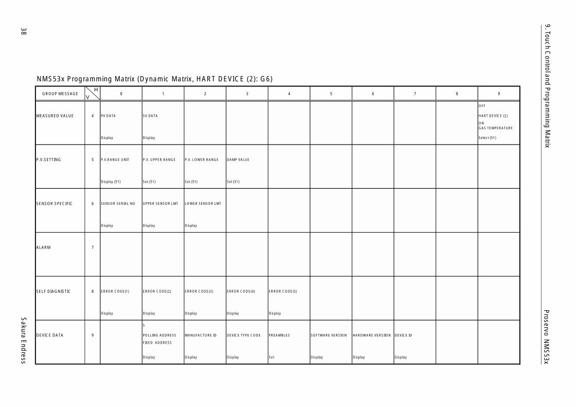
GROUP MESSAGE 0 1 2 3 4 5 6 7 8 9
OFF
MEASURED VALUE 4 PV DATA SV DATA HART DEVICE (1)
Display Display
ONLIQUID TEMP.GAS TEMPERATURESelect (51)
P.V.SETTING 5 P.V.RANGE UNIT P.V. UPPER RANGE P.V. LOWER RANGE DAMP VALUE
Display (51) Set (51) Set (51) Set (51)
SENSOR SPECIFIC 6 SENSOR SERIAL NO UPPER SENSOR LMT LOWER SENSOR LMT
Display Display Display
ALARM 7
SELF DIAGNISTIC 8 ERROR CODE(1) ERROR CODE(2) ERROR CODE(3) ERROR CODE(4) ERROR CODE(5)
Display Display Display Display Display
4
DEVICE DATA 9 POLLING ADDRESS MANUFACTURE ID DEVICE TYPE CODE PREAMBLES SOFTWARE VERSION HARDWARE VERSIION DEVICE ID
FIXED ADDRESS
Display Display Display Set Display Display Display
VH
38S
akura End
ress
Proservo N
MS
53x9. Touch C
ontrol and P
rogram
ming
Matrix
NMS53x Programming Matrix (Dynamic Matrix, HART DEVICE (2): G6)
GROUP MESSAGE 0 1 2 3 4 5 6 7 8 9
OFF
MEASURED VALUE 4 PV DATA SV DATA HART DEVICE (2)
Display Display
ONGAS TEMPERATURE
Select (51)
P.V.SETTING 5 P.V.RANGE UNIT P.V. UPPER RANGE P.V. LOWER RANGE DAMP VALUE
Display (51) Set (51) Set (51) Set (51)
SENSOR SPECIFIC 6 SENSOR SERIAL NO UPPER SENSOR LMT LOWER SENSOR LMT
Display Display Display
ALARM 7
SELF DIAGNISTIC 8 ERROR CODE(1) ERROR CODE(2) ERROR CODE(3) ERROR CODE(4) ERROR CODE(5)
Display Display Display Display Display
5
DEVICE DATA 9 POLLING ADDRESS MANUFACTURE ID DEVICE TYPE CODE PREAMBLES SOFTWARE VERSION HARDWARE VERSIION DEVICE ID
FIXED ADDRESS
Display Display Display Set Display Display Display
VH
Sakura E
ndress
39
Proservo N
MS
53x9. Touch C
ontrol and P
rogram
ming
Matrix
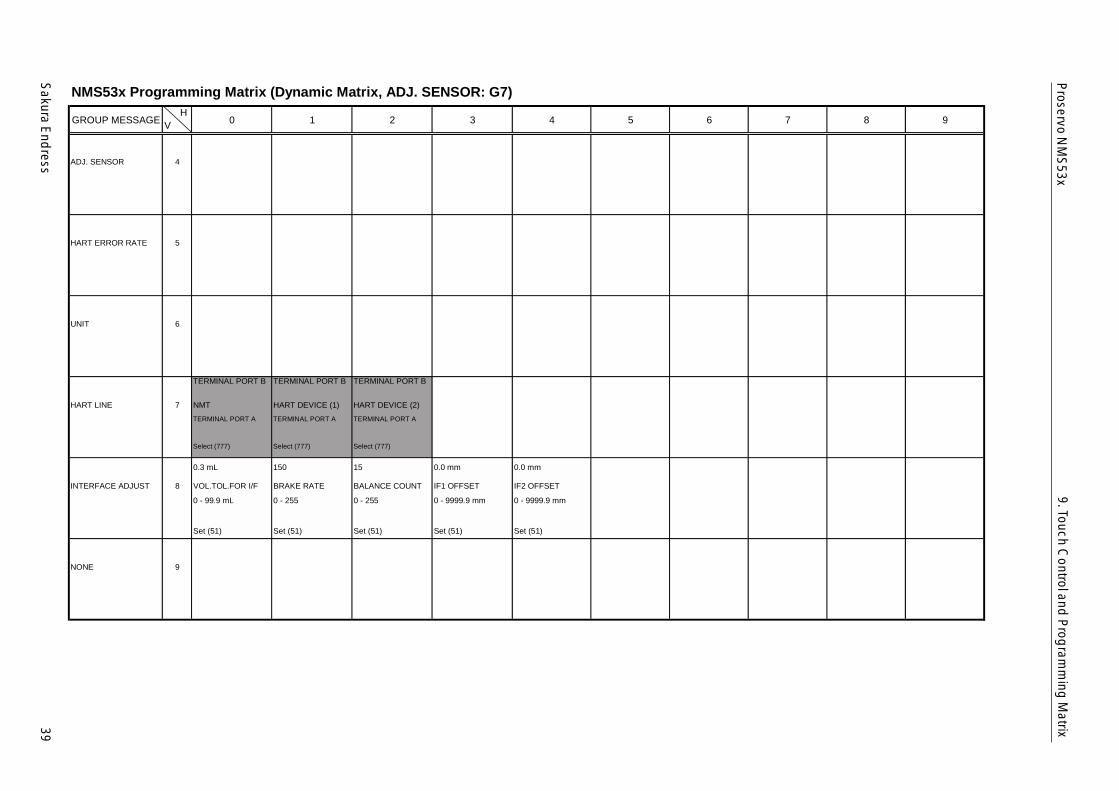
NMS53x Programming Matrix (Dynamic Matrix, ADJ. SENSOR: G7)
GROUP MESSAGE 0 1 2 3 4 5 6 7 8 9
ADJ. SENSOR 4
HART ERROR RATE 5
UNIT 6
TERMINAL PORT B TERMINAL PORT B TERMINAL PORT B
HART LINE 7 NMT HART DEVICE (1) HART DEVICE (2)TERMINAL PORT A
Select (777)
TERMINAL PORT A
Select (777)
TERMINAL PORT A
Select (777)
0.3 mL 150 15 0.0 mm 0.0 mm
INTERFACE ADJUST 8 VOL.TOL.FOR I/F BRAKE RATE BALANCE COUNT IF1 OFFSET IF2 OFFSET
0 - 99.9 mL
Set (51)
0 - 255
Set (51)
0 - 255
Set (51)
0 - 9999.9 mm
Set (51)
0 - 9999.9 mm
Set (51)
NONE 9
VH
40S
akura End
ress
Proservo N
MS
53x9. Touch C
ontrol and P
rogram
ming
Matrix
10.7 Descrip
tion of th
e Prog
ramm
ing
Matrix
Matrix group Function group Item Accesscode
Short description Default vaule SetSelectDisplay
Possible settings,selections, or displays
Index No,GVH
STATIC MATRIX(This word is notshown)
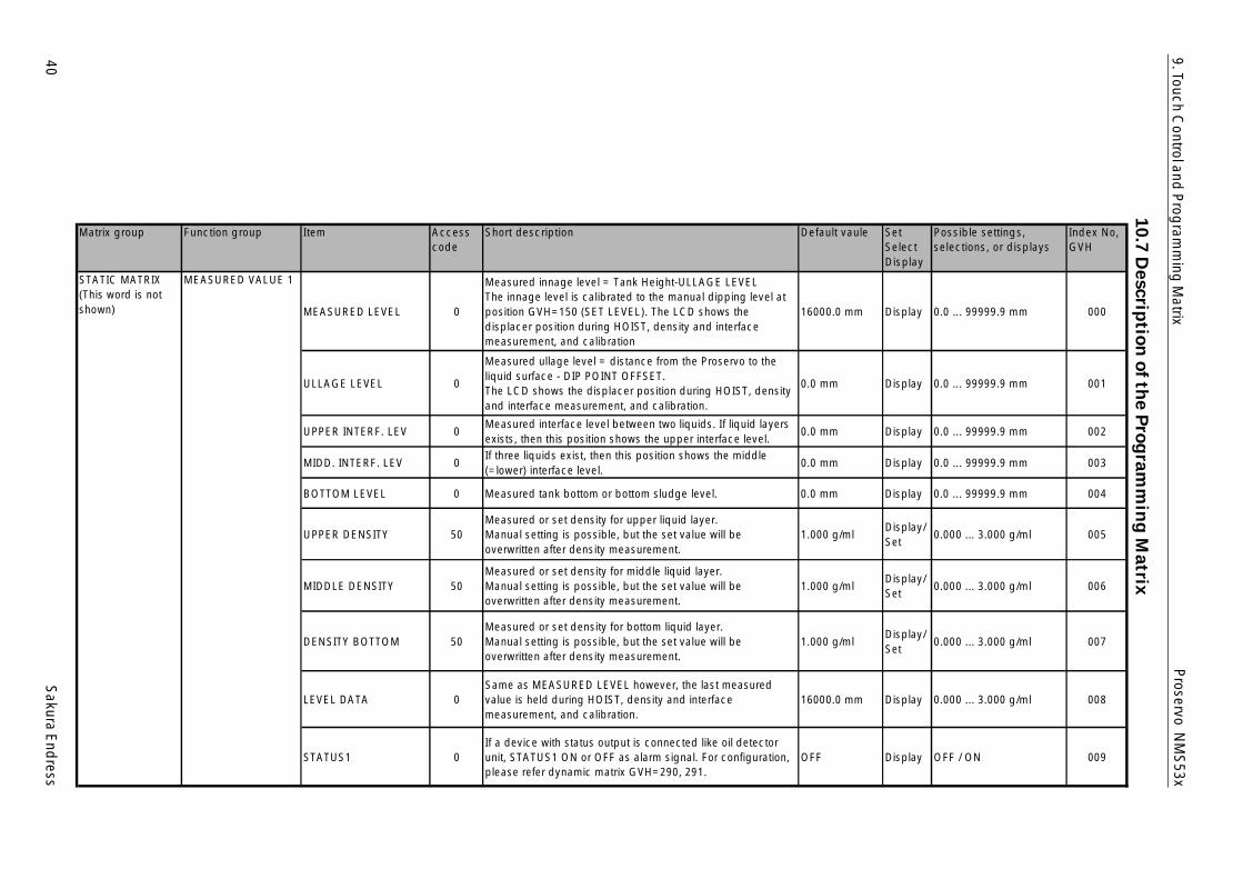
MEASURED VALUE 1
MEASURED LEVEL 0
Measured innage level = Tank Height-ULLAGE LEVELThe innage level is calibrated to the manual dipping level atposition GVH=150 (SET LEVEL). The LCD shows thedisplacer position during HOIST, density and interfacemeasurement, and calibration
16000.0 mm Display 0.0 ... 99999.9 mm 000
ULLAGE LEVEL 0
Measured ullage level = distance from the Proservo to theliquid surface - DIP POINT OFFSET.The LCD shows the displacer position during HOIST, densityand interface measurement, and calibration.
0.0 mm Display 0.0 ... 99999.9 mm 001
UPPER INTERF. LEV 0Measured interface level between two liquids. If liquid layersexists, then this position shows the upper interface level.
0.0 mm Display 0.0 ... 99999.9 mm 002
MIDD. INTERF. LEV 0If three liquids exist, then this position shows the middle(=lower) interface level.
0.0 mm Display 0.0 ... 99999.9 mm 003
BOTTOM LEVEL 0 Measured tank bottom or bottom sludge level. 0.0 mm Display 0.0 ... 99999.9 mm 004
UPPER DENSITY 50Measured or set density for upper liquid layer.Manual setting is possible, but the set value will beoverwritten after density measurement.
1.000 g/mlDisplay/Set
0.000 ... 3.000 g/ml 005
MIDDLE DENSITY 50Measured or set density for middle liquid layer.Manual setting is possible, but the set value will beoverwritten after density measurement.
1.000 g/mlDisplay/Set
0.000 ... 3.000 g/ml 006
DENSITY BOTTOM 50Measured or set density for bottom liquid layer.Manual setting is possible, but the set value will beoverwritten after density measurement.
1.000 g/mlDisplay/Set
0.000 ... 3.000 g/ml 007
LEVEL DATA 0Same as MEASURED LEVEL however, the last measuredvalue is held during HOIST, density and interfacemeasurement, and calibration.
16000.0 mm Display 0.000 ... 3.000 g/ml 008
STATUS1 0If a device with status output is connected like oil detectorunit, STATUS1 ON or OFF as alarm signal. For configuration,please refer dynamic matrix GVH=290, 291.
OFF Display OFF / ON 009
Sakura E
ndress
41
Proservo N
MS
53x9. Touch C
ontrol and P
rogram
ming
Matrix
Matrix group Function group Item Accesscode
Short description Default vaule SetSelectDisplay
Possible settings,selections, or displays
Index No,GVH
STATIC MATRIX(This word is notshown)
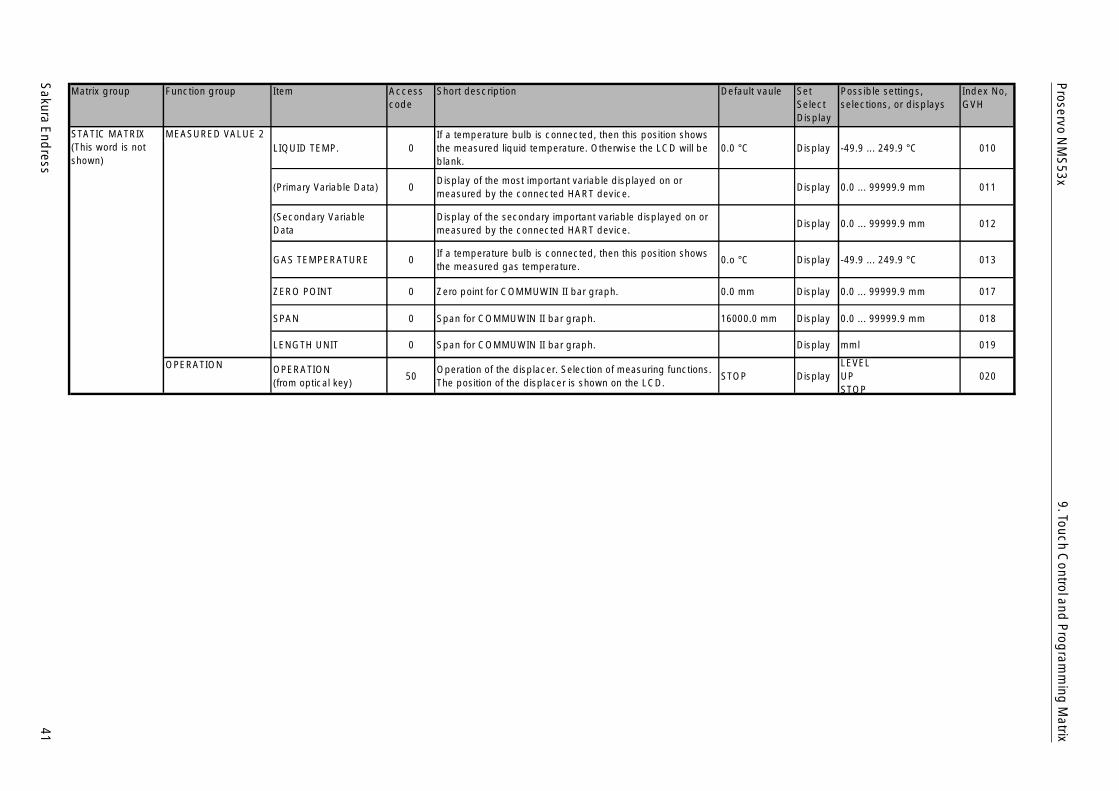
MEASURED VALUE 2LIQUID TEMP. 0
If a temperature bulb is connected, then this position showsthe measured liquid temperature. Otherwise the LCD will beblank.
0.0 °C Display -49.9 ... 249.9 °C 010
(Primary Variable Data) 0Display of the most important variable displayed on ormeasured by the connected HART device.
Display 0.0 ... 99999.9 mm 011
(Secondary VariableData
Display of the secondary important variable displayed on ormeasured by the connected HART device.
Display 0.0 ... 99999.9 mm 012
GAS TEMPERATURE 0If a temperature bulb is connected, then this position showsthe measured gas temperature.
0.o °C Display -49.9 ... 249.9 °C 013
ZERO POINT 0 Zero point for COMMUWIN II bar graph. 0.0 mm Display 0.0 ... 99999.9 mm 017
SPAN 0 Span for COMMUWIN II bar graph. 16000.0 mm Display 0.0 ... 99999.9 mm 018
LENGTH UNIT 0 Span for COMMUWIN II bar graph. Display mml 019
OPERATION OPERATION(from optical key)
50Operation of the displacer. Selection of measuring functions.The position of the displacer is shown on the LCD.
STOP DisplayLEVELUPSTOP
020
42S
akura End
ress
Proservo N
MS
53x9. Touch C
ontrol and P
rogram
ming
MatrixMatrix group Function group Item Access
codeShort description Default vaule Set
SelectDisplay
Possible settings,selections, or displays
Index No,GVH
STATIC MATRIX(This word is notshown)
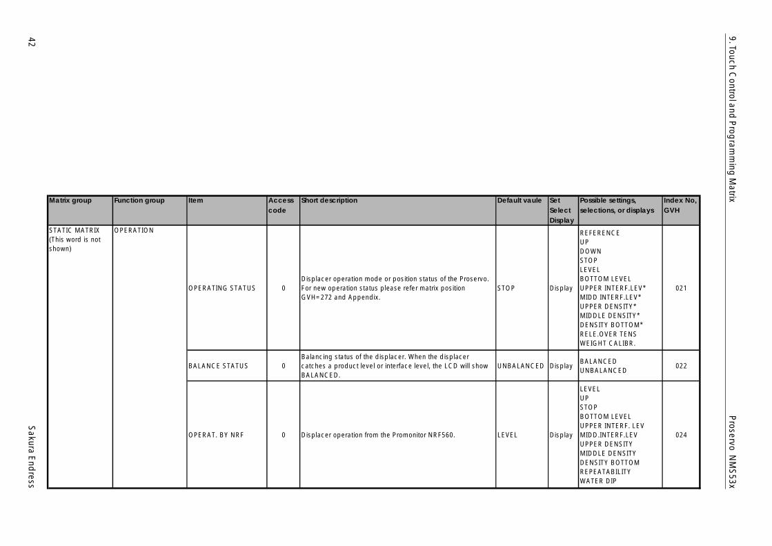
OPERATION
OPERATING STATUS 0Displacer operation mode or position status of the Proservo.For new operation status please refer matrix positionGVH=272 and Appendix.
STOP Display
REFERENCEUPDOWNSTOPLEVELBOTTOM LEVELUPPER INTERF.LEV*MIDD INTERF.LEV*UPPER DENSITY*MIDDLE DENSITY*DENSITY BOTTOM*RELE.OVER TENSWEIGHT CALIBR.
021
BALANCE STATUS 0Balancing status of the displacer. When the displacercatches a product level or interface level, the LCD will showBALANCED.
UNBALANCED DisplayBALANCEDUNBALANCED
022
OPERAT. BY NRF 0 Displacer operation from the Promonitor NRF560. LEVEL Display
LEVELUPSTOPBOTTOM LEVELUPPER INTERF. LEVMIDD.INTERF.LEVUPPER DENSITYMIDDLE DENSITYDENSITY BOTTOMREPEATABILITYWATER DIP
024

Sakura E
ndress
43
Proservo N
MS
53x9. Touch C
ontrol and P
rogram
ming
Matrix
Matrix group Function group Item Accesscode
Short description Default vaule SetSelectDisplay
Possible settings,selections, or displays
Index No,GVH
STATIC MATRIX(This word is notshown)
OPERATION
OPERAT. BY HOST 0Displacer operation from a host system i.e. NXS310,NR30(MDP-II), NRS, NRM, COMMUWIN II, FuelsManager,etc.
LEVEL Display
LEVELUPSTOPBOTTOM LEVELUPPER INTERF. LEVMIDD.INTERF.LEVUPPER DENSITYMIDDLE DENSITYDENSITY BOTTOMREPEATABILITYWATER DIP
025
DEVICE ID 0 Displays a device ID 411 Display 028
SOFTWARE ID 0 Displays a software ID 8424 Display 029
MORE FUNCTION
MATRIX OF 0 Selection of the dynamic matrix of the programming matrix CALIBRATION Select
CALIBRATIONDEVICE DATASERVICETEMPERATUREHART DEVICE (1)HART DEVICE (2)ADJ. SENSOR
030
(Calendar) 0Calendar and clock without daylight saving system.NOT TRANSFERRED BY RACKBUS.
Japaneselocal time
Displaye.g. 1 410 19:10:41Year Month DayHH:MM:SS
033
ALARM CONTACT 0 Alarm message display, depending on current conditions. Display Alam message 034
(Alarm Message) 0Previous alarm with message.Only the last alarm code is transmitted by Rackbus.
DisplayAlarm message (refer toattached table)
035
DIAGNOSTIC CO 0 Self diagnosis at the moment DisplayError message (refer toattached table)
036

44S
akura End
ress
Proservo N
MS
53x9. Touch C
ontrol and P
rogram
ming
Matrix
Matrix group Function group Item Accesscode
Short description Default vaule SetSelectDisplay
Possible settings,selections, or displays
Index No,GVH
STATIC MATRIX(This word is notshown)
MORE FUNCTION(Erroneous Message) 0
Previous alarm with message.Only the last alarm code is transmitted by Rackbus.
(ErroneousDate)
DisplayError message(refer to attached table)
037
ACCESS CODE 0 Access code for programming (see Sec. 10.4) 0 Set 0 ... 9999 039
CALIBRATION LEVEL DATA
TANK HEIGHT 50Elevation level of the manual dipping reference.This level is normally considered as tank height or dip pointreference.
16000.0 mm Set 0 ... 99999.9 mm 140
DIP POINT OFFSET 50Deference between elevation of the reference line of theProservo NMS5/7 and dipping reference (TANK HEIGHT).
0.0 mm Set -99999.9 ... 99999.9 mm 141
DISPLACER DRAUGHT 50Draught of the displacer. This value is used for calibration ofthe Proservo NMS5/7, when the tank is empty.
10.0 mm Set 0.0 ... 999.9 mm 142
DISPL. RAIS DENS 51Value of the displacer hoisted from surface or interface whendensity measurement is activated.
150 mm.. Set 0 ... 300 mm 143
DISPL. SUBM DENS.Value for the displacer lowered from surface or interfacewhen density measurement is activated.
150 mm.. Set 0 ... 1500 mm 144
CALIBRATIONSET LEVEL 50
Calibration or setting of level data. Level indication can be setto manual dipping or other data in this mode. The dip pointoffset will be changed according to the set here.
16000.0 mm Set 0.0 ... 99999.9 mm 150
TANK CORRECT LEV 51Start level for tank roof compensation by level. Thiscompensation is required in case of tank roof distortion dueto hydrostatic pressure on the tank wall.
0.0 mm Set 0.0 ... 99999.9 mm 152
TANK CORRE. COEF 51 Linear coefficient for tank roof compensation by level. 0.000 mm7m Set 0.000 ... 59.999 mm/m 153
ADJUSTMENTUPPER STOP 50 Upper limit of displacer motion. 16000 mm Set 0 ... 99999 mm 160
LOWER STOP 50 Lower limit of displacer motion. 0 mm Set 0 ... 99999 mm 161
SET OVER TENS. 51Over tension value of the measuring wire. If the tensionexceeds this value, then the Proservo stops operation, and anerror message will be displayed.
350 g Set 0 ... 999 g 162

Sakura E
ndress
45
Proservo N
MS
53x9. Touch C
ontrol and P
rogram
ming
Matrix
Matrix group Function group Item Accesscode
Short description Default vaule SetSelectDisplay
Possible settings,selections, or displays
Index No,GVH
CALIBRATION ADJUSTMENT
SET UNDER TENS. 51Under tension value of the measuring wire. If the tension fallsbelow this value, then the Proservo stops operation, and anerror message will be displayed.
50 g Set 0 ... 999 g 163
SLOW HOIST 51
Slow speed hoisting of the displacer to avoid the displacerhitting the opening of the mounting nozzle. If the size of thenozzle is less than or equal to 3" then set the value graterthan the length of the nozzle +60 mm.
60 mm Set 60 ... 1800 mm 164
DISPL. RAIS. REP. 51 Set a hoist distance for displacer under repeatability testing. 10 mm Set 10 ... 99 mm 165
DISPL. WAIT REP. 51Set a waiting time for displacer movement after hoist upunder repeatability testing.
10 s Set 10 ... 999 s 166
DISPL. WAIT DIP. 51Set a waiting time for displacer movement back to levelmeasurement under water dipping function.
10 s Set 10 ... 999 s 167
AUTO WIRE CALIB.
CALIBR. AUTO/MAN. 51
Wire length calibration. When MANUAL is selected, theProservo hoists the wire in the drum housing, and thenmeasures the liquid surface again. By AUTO, the Proservohoists the wire in accordance with set START TIME andINTERVAL TIME.
NONE SetNONEMANUALAUTOMATIC
170
START TIME 51 Start time of wire calibration when AUTO mode is selected. Sete.g. 12 31 23
month date time (hour)171
INTERVAL TIME 51 Interval of wire calibration when AUTO mode as selected. 0 hour Select 0 ... 9999 hour 172
AUTO COMPENSAT. 51 Automatic compensation of length data. OFF DisplayOFFON
173
ZERO CORRECTION 51Zero correction of length when the wire is hoisting from theliquid.
0.0 mm Display 0 ... 99999.9 mm 174
COMPENS. LIMIT 51Allowable deviation of level after level calibration. If thedeviation exceeds the set value, then an alarm will beemitted.
0.0 mm Set 0.0 ... 99999.9 mm 175

46S
akura End
ress
Proservo N
MS
53x9. Touch C
ontrol and P
rogram
ming
Matrix
Matrix group Function group Item Accesscode
Short description Default vaule SetSelectDisplay
Possible settings,selections, or displays
Index No,GVH
CALIBRATION AUTO CALIB. DISPL.
CALIBR. AUTO/MAN. 51
Displacer weight calibration. When MANUAL is selected, theProservo hoists the displacer in the gas phase, once checksits weight, and then measures the liquid surface again. ByAUTO, the Proservo hoists the displacer in accordance withset START TIME and INTERVAL TIME.
NONE SetNONEMANUALAUTOMATIC
180
START TIME 51 Start time of weight calibration when AUTO mode is selected. Sete.g. 12 31 23
month date time (hour)181
INTERVAL TIME 51 Interval of weight calibration when AUTO mode as selected. 0 hour Select 0 ... 9999 hour 182
AUTO COMPENSAT. 51 Automatic compensation of weight data. OFF DisplayOFFON
183
DEVIATION 51Deviation of weight when the displacer is hoisting from theliquid.
0.0 g Display 0.0 ... 99.9 g 184
COMPENS. LIMIT 51Allowable deviation of weight after weight calibration. If"CAUTION" has been selected on GVH=241, and thedeviation exceeds the set value and alarm will be emitted.
0.0 g Set 0.0 99.9 g 185
DISPLAYSELECT DISP. MODE 51 Selection of level display at HOME position: innage or ullage.
MEASUREDLEVEL
SelectMEASURED LEVELULLAGE LEVEL
190
LANGUAGE 51 Language that all text is to be displayed in. ENGLISH SelectENGLISH JAPANESE(with original characters)
191
LCD CONTRAST 51 The display contrast in 16 phases. 12th Phase SetAdjust brightenesswiththe "+" or "-" keys
192
YEAR SETTING 51 Calendar year. Current year Set 0 ...99 193
MONTH SETTING 51 Calendar month. Current month Set 1 ... 12 194
DAY SETTING 51 calendar day. Current day Set 0 ... 31 195
HOUR SETTING 51 Hour Current hour Set 0 ... 23 196
MINUTE SETTING 51 Minute. Clock starts from 0 s when minute is set. Current minute Set 0 ... 59 197
Note!- The default
va lues ofc a lenda r andc loc k refer toJapanese loca ltime.
- A daylightsaving
func tion is notava ilab le

Sakura E
ndress
47
Proservo N
MS
53x9. Touch C
ontrol and P
rogram
ming
Matrix
Matrix group Function group Item Accesscode
Short description Default vaule SetSelectDisplay
Possible settings,selections, or displays
Index No,GVH
CALIBRATION DISPLAY SELECT DECIMAL 51 Selection of decimal point indication by dot or comma. [.] Select[.][,]
198
LCD CHECK 51
The condition of the LCD's display section is checked. If thedisplay is in good condition, the whole screen will darken for3 second when "ON" is selected; and it will lighten for thesame period of time when "OFF" is selected.
OFF SelectOFFON
199
DEVICE DATA CONTACT OUTPUTSELECT. RELAY 50 Selection of output relay. 1 Select 1 ... 4 (standard) 240
ASSIGN RELAY 50Selection of relay contact define by SELECT.RELAY. Thecontacts will be activated corresponding to the selectedmode.
NONE Select
NONELEVELLIQUID TEMP.CAUTIONWARNINGEMERGENCY ERRORBALANCE SIGNAL
241
RELAY FUNCTION 50Selection of an alarm message concerning the specifiedalarm/error output relay. Selected only when "LEVEL" or"LIQUID TEMP." is selected on matrix GVH0241.
HIGH SelectHIGHLOW
242
SWITCHING POINT 50Selection of the alarm activation level of the specifiedalarm/error output relay. Selectable only when "LEVEL" or"LIQUID TEMP." is selected on matrix GVH=241.
0 mm Set0 ... 99999 mm-999 ... 999 °C
243
HYSTERESIS 50Set the hysteresis value at which the alarm of the selectedalarm/error output relay is deactivated. Can be set only when"LEVEL" or "LIQUID TEMP." is selected on matrix GVH=241.
0 mm Set0 ... 99999 mm-999 ... 999 °C
244
RELAY ON ALARM 50
Selection of the output action of the specified alarm/erroroutput relay. Selectable only when "LEVEL" or "LIQUID TEMP."is selected on matrix GVH=241.NOTE: Turning off the power does not affect the alarm/erroroutput contact point.
NORMALOPENED
SelectNORMAL OPENEDNORMAL CLOSED
245
Note!- The wholematrix is ava ilab lewhen relayoutput is insta lled .

48S
akura End
ress
Proservo N
MS
53x9. Touch C
ontrol and P
rogram
ming
Matrix
Matrix group Function group Item Accesscode
Short description Default vaule SetSelectDisplay
Possible settings,selections, or displays
Index No,GVH
DEVICE DATA CONTACT OUTPUT
ON DELAY TIME 50Set the alarm output start delay for the selected alarm/erroroutput relay is deactivated. Can be set only when "LEVEL" or"LIQUID TEMP." is selected on matrix GVH=241.
0 s Set 0 ... 999s 246
OFF DELAY TIME 50Set the alarm output stop delay for the selected alarm/erroroutput relay is deactivated. Can be set only when "LEVEL" or"LIQUID TEMP." is selected on matrix GVH=241.
0 s Set 0 ... 999s 247
ANALOG OUT. ADJUSASSIGN OUTPUT 1 50 Assignment of analogue output channel 1. NONE Select
NONEMANUALAUTOMATIC
250
ADJUST 4 mA 50Sets output channel 1 (DC 4 - 20mA) to transmit a DC 4 mAcurrent. Ban be set only when "LEVEL" or "LIQUID TEMP." isselected at matrix position GVH=250
0 mm Set0 ... 99999 mm-999 ... 999 °C
251
ADJUST 20 mA 50Sets output channel 1 (DC 4 - 20mA) to transmit a DC 20 mAcurrent. Ban be set only when "LEVEL" or "LIQUID TEMP." isselected at matrix position GVH=250
0 mm Set0 ... 99999 mm-999 ... 999 °C
252
ASSIGN OUTPUT 2 50 Assignment of analogue output channel 2. NONE SelectNONEMANUALAUTOMATIC
253
ADJUST 4 mA 50Sets output channel 2 (DC 4 - 20mA) to transmit a DC 4 mAcurrent. Ban be set only when "LEVEL" or "LIQUID TEMP." isselected at matrix position GVH=250
0 mm Set0 ... 99999 mm-999 ... 999 °C
254
ADJUST 20 mA 50Sets output channel 2 (DC 4 - 20mA) to transmit a DC 20 mAcurrent. Ban be set only when "LEVEL" or "LIQUID TEMP." isselected at matrix position GVH=250
0 mm Set0 ... 99999 mm-999 ... 999 °C
255
DEVICE AT ALARM 50
An error causes output channels 1 and 2 (DC 4-20mA) totransmit the preset current(s).HOLD: the output channels continue transmitting the currentthe were transmitting before the error.MAX: The output channels switch to transmit a 20mA current.MIN: The output channels switch to transmit 4mA current.
OFF Select
OFFHOLD CURRENT PUTMAXMIN
256
PARTS DATAPARTS NUMBER 51 Sets the number of the control-target parts. 1 Select 1 ... 10 260
Note!- The wholema trix is ava ilab lewhen ana logueoutput is insta lled .
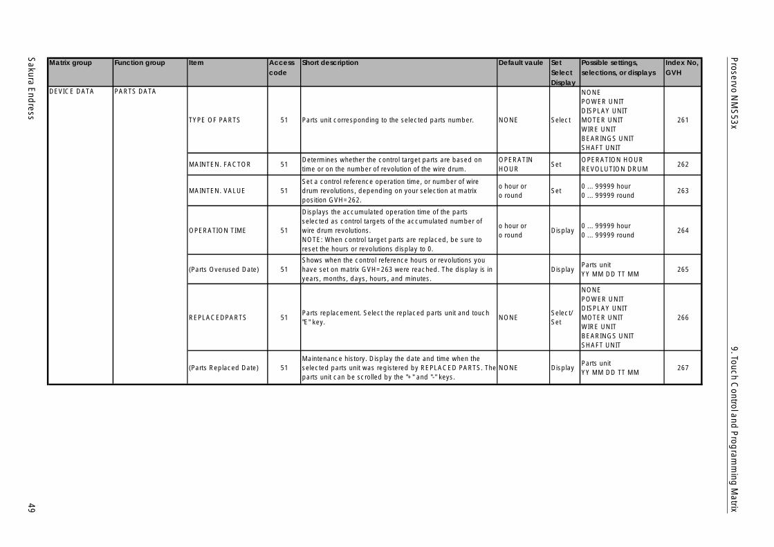
Sakura E
ndress
49
Proservo N
MS
53x9. Touch C
ontrol and P
rogram
ming
Matrix
Matrix group Function group Item Accesscode
Short description Default vaule SetSelectDisplay
Possible settings,selections, or displays
Index No,GVH
DEVICE DATA PARTS DATA
TYPE OF PARTS 51 Parts unit corresponding to the selected parts number. NONE Select
NONEPOWER UNITDISPLAY UNITMOTER UNITWIRE UNITBEARINGS UNITSHAFT UNIT
261
MAINTEN. FACTOR 51Determines whether the control target parts are based ontime or on the number of revolution of the wire drum.
OPERATINHOUR
SetOPERATION HOURREVOLUTION DRUM
262
MAINTEN. VALUE 51Set a control reference operation time, or number of wiredrum revolutions, depending on your selection at matrixposition GVH=262.
o hour oro round
Set0 ... 99999 hour0 ... 99999 round
263
OPERATION TIME 51
Displays the accumulated operation time of the partsselected as control targets of the accumulated number ofwire drum revolutions.NOTE: When control target parts are replaced, be sure toreset the hours or revolutions display to 0.
o hour oro round
Display0 ... 99999 hour0 ... 99999 round
264
(Parts Overused Date) 51Shows when the control reference hours or revolutions youhave set on matrix GVH=263 were reached. The display is inyears, months, days, hours, and minutes.
DisplayParts unitYY MM DD TT MM
265
REPLACEDPARTS 51Parts replacement. Select the replaced parts unit and touch"E" key.
NONESelect/Set
NONEPOWER UNITDISPLAY UNITMOTER UNITWIRE UNITBEARINGS UNITSHAFT UNIT
266
(Parts Replaced Date) 51Maintenance history. Display the date and time when theselected parts unit was registered by REPLACED PARTS. Theparts unit can be scrolled by the "+" and "-" keys.
NONE DisplayParts unitYY MM DD TT MM
267
50S
akura End
ress
Proservo N
MS
53x9. Touch C
ontrol and P
rogram
ming
Matrix
Matrix group Function group Item Accesscode
Short description Default vaule SetSelectDisplay
Possible settings,selections, or displays
Index No,GVH
DEVICE DATA INPUT SIGNAL
OPE. CONTACTThis is an optionalfunction, and is notavailable unless thecontact input unit isconnected.
51
Displacer operation by contact input. If ON is selected, thenthe operation will be as follows:
Contact Operation1 off, 2 off LEVEL1 on, 2 off UP1 off, 2 on STOP1 on, 2 on INTERFACE
OFF SelectONNON (2 contacts)
270
CUSTODY TRANSFER 0
Shows whether the custody transfer mode, which does notallow any internal data to change one the apparatus isselected after customs duties have been paid, is active(regarding custody transfer, refer to Appendix D). Use thisfunction when the apparatus is mounted to a tank withcustody transfer feature. In addition, "ON" will be displayed ifa switch in in a sealed mode.
OFF Display
OFF (Non custodytransfer mode)ON (Custody transfermode)
271
SOFTWARE VERSION 0 Software version of the Proservo NMS5/7 4.24 Display 275
HARDWARE VERSION 0 Hardware version of the Proservo NMS5/7 4.11 Display 276
OPE. DENSITY 51
This is a function conforming to PTB and NMi specificationsthat is used to set the liquid density setting for computingbuoyancy from a given balance volume in custody transfermode. (See Appendix C.) Ulterior level measurements do notafter the value you specify here.
1.0 g/ml Set 0.0 ... 3.0 g/ml 278
OPE. CONT. STATUS 51
Displays the terminal numbers in use (binary data conversedto their decimal equivalents).NOTE: This is an optional function, and is not available unlessthe contact input unit is connected.
0 Set 0 ... 255 279
COMMUNICATION
LEVEL ALARM 1 51Select an upper/lower limit on innage level relative to thesetting of ALARM 1 for bi-directional two-wirecommunications.
HIGH SelectNONEHIGHLOW
280
Sakura E
ndress
51
Proservo N
MS
53x9. Touch C
ontrol and P
rogram
ming
Matrix
Matrix group Function group Item Accesscode
Short description Default vaule SetSelectDisplay
Possible settings,selections, or displays
Index No,GVH
DEVICE DATA COMMUNICATIONSET LEVEL ALARM 1 51
Sets either the upper or the lower alarm activation level, asspecified on matrix GVH=280.
0.0 mm Set 0.0 ... 99999.9 mm 281
LEVEL ALARM 2 51Select an upper/lower limit on innage level relative to thesetting of ALARM 2 for bi-directional two-wirecommunications.
HIGH SelectNONEHIGHLOW
282
SET LEVEL ALARM 2 51Sets either the upper or the lower alarm activation level, asspecified on matrix GVH=280.
0.0 mm Set 0.0 ... 99999.9 mm 283
HYSTERESIS 51
Sets a hysteresis for the alarm setting for bi-directional two-wire communications. Hysteresis here refers to the differencebetween the level at which the alarm is deactivated and thespecified upper/lower limit. The alarm is deactivated whenthe liquid surface nears its normal height, the rising orlowering volume exceeding that difference.
0.0 mm Set 0.0 ... 99999.9 mm 284
ADDRESS 51Sets an address for remote communication. A number for bi-directional two-wire communications is also specified here.
0 Set
0 - 9A - F (for MIC: FF fixed)Total 16 addressed canbe set.
285
PROTOCOL 51 Selection of communication protocols. WM550 / MS Select
WM550 / MSBBB (MIC)MDPV1 / BPMRACKBUS (RS485)HART
286
COMMU. LINE ADJ. 51 Line resistance for serial pulse output (Sakura protocol). F Set
0 - 9A - F (for MIC: FF fixed)Total 16 addressed canbe set.
287
COMMUNIC. STATUS 51 Display of the communication status of the digital output. 0 Display 288
STATUSSTATUS1 DELAY 51 Set a detay time for status 1 input. 0 S Set 0 ... 99 s 290

52S
akura End
ress
Proservo N
MS
53x9. Touch C
ontrol and P
rogram
ming
Matrix
Matrix group Function group Item Accesscode
Short description Default vaule SetSelectDisplay
Possible settings,selections, or displays
Index No,GVH
DEVICE DATA STATUS
SELECT CONTACT 51
Select a contact tape as follows:- NONE- NORMAL OPENED- NORMAL CLOSED
NONE SelectNONENORMAL OPENEDNORMAL CLOSED
291
BALANCE DELAY 51Set a delay time for balance status according to the matrixposition GVH=241.
0 S Set 0 ... 99 s 299
SERVICE MEAS. WIRE & DRUMWIRE DRUM CIRC. 51
Circumference of the wire drum. Set the data marked on thewire drum.
300.00 mm Set 0.00 ... 599.99 mm 340
WIRE WEIGHT 51
Measuring wire weight per 10 m wire.- Stainless steel SUS316: 1.4 g / 10 m- PTFE coated wire: 4.55 g / 10 m- Hasteloy C wire : 2.48 g / 10 m
1.4 g / 10 m Set 0.00 ... 99.99 g / 10 m 341
DISPLACER WEIGHT 51 Displacer weight. Set the value marked on the displacer. 255.0 g Set 0.0 ... 999.9 g 342
DISPLACER VOLUME 51 Displacer volume. Set the value marked on the displacer. 145.0 ml Set 0.0 ... 999.9 ml 343
BALANCE VOLUME 51Volume submerged in the liquid. For interface measurement,this is the volume submerged in the lower liquid. Set thevalue marked on the displacer.
60 ml Set 0.0 ... 999.9 ml 344
VOLUME TOLERANCE 51
Set the valid tolerance volume when the displacer is in abalanced state. This setting specifies the immunity of thedisplacer to level variation, beyond which the displacer willstart moving and abandon ist balancing position.- Displacer less the 70 ml in diameter: 1.0 ml- Displacer less the 110 ml in diameter: 5.0 ml
1.0 ml Set 0.0 ... 99.9 ml 345
DELAY 51
Set the interval before the displacer responds to a liquid levelvariation that exceeds the preset VOLUME TOLERANCE. Toprevent the displacer from responding to a momentarydisturbance in the liquid's surface, the Proservo understandsthat the displacer returns to temporary balancing conditiononly after a certain time has passed.
5 x 100 ms Set 0 ... 99 x 100 ms 347
Sakura E
ndress
53
Proservo N
MS
53x9. Touch C
ontrol and P
rogram
ming
Matrix
Matrix group Function group Item Accesscode
Short description Default vaule SetSelectDisplay
Possible settings,selections, or displays
Index No,GVH
SERVICE MEAS. WIRE & DRUM
DRUM CORRECTION 51
Set the correction value to compensate for possible errorsduring one revolution of the wire drum.When drum circumference value has been input, drumcorrection is not required.
0.00 mm/m Set 0.00 ... 99.99 mm/m 348
HUNTING COUNT 51
Defines the number of huntings when the displacer touchesthe solid surfaces. If the set value is greater than or equal to1, then the displacer moving speed slows down when thehuntings exceeds the set count.
0 count Set 9 ... 999 count 349
GAUGE DATA
NON-HYSTER. MODE 51
Non-hysteresis measuring mode. If On is selected, then theProservo will raise the displacer approx. 2 mm from the liquidsurface after balancing and measure slowly downward. Thismode allows measurement without hysteresis.
OFF SelectOFFON
352
HI. ACCURACY MODE 51
Hi accuracy measurement. This is carried out in two phases,namely temporary and precise balance on the liquid surface.The Proservo hoists the displacer when it registers thetemporary balance and weighs it. The displacer comes downslowly afterwards and registers the precise balance.
OFF SelectOFFON
353
HI. ACCR-OPE.TIME 51
If the high accuracy measurement mode is activated, and theliquid surface ripples, the displacer goes into a temporarybalanced state. Thereafter, the displacer is hoisted once tomeasure ist weight again. You can here specify the delaybetween when the displacer goes into its temporary balancedstate and when it is weighed.
0 s Set 0 ... 600 s 354
HI.ACC.DISP.UP 51Sets the height to which the displacer is hoisted to measureist weight after the interval specified on matrix GVH=354 haspassed.
0 mm Set 0 ... 300 mm 355
GAUGE TEMP. 51 Temperature in the Proservo Current data Display -999 ... 999 °C 356
54S
akura End
ress
Proservo N
MS
53x9. Touch C
ontrol and P
rogram
ming
Matrix
Matrix group Function group Item Accesscode
Short description Default vaule SetSelectDisplay
Possible settings,selections, or displays
Index No,GVH
SERVICE SYSTEM DATA
SENSOR DATA 51 The Proservo specification. Display
SOFTWARE VERSIONHARDWARE VERSIONREMOTE COM. ONREMOTE COM. OFFGEAR 1:36NOT OVERSPILL
360
CONNECTION NRF 51 Connection of the Promonitor NRF560. OFF Select
OFFCONTACT 1 (connectedto old type)CONTACT 2 (connectedto new type)
361
CONNECTION NMT 51 Connection of the Prothermo NMT53x series. OFF Select
OFFSPOT (three wire RTDinput)Average (NMT535/6/7)
362
SOFT RESET 51Restart the Proservo software. If ON is selected then thesoftware will start from the beginning as soon as powersupply is switched on.
OFF SelectOFFON
369
SERVICE
MEASURED WEIGHT 51Measured displacer weight by the Proservo.NOTE: Before weight calibration measured weight shows 0.0g.
Display 0.0 ... 999 g 370
RELE. OVER TENS. 51Release of overtension error from the displacer. If ON isselected, then the displacer will slowly till overtension error iscancelled. * Set OPERATION = STOP first.
OFF SelectOFFON
371
DRUM SETTING 51Adjustment of the internal unit of the Proservo and the wiredrum.
OFF SelectOFFON
372
WEIGHT CALIBR. 51Calibration of weight data for the initialization of the Proservo.If ON is selected, then follow the instructions on the LCDdisplay.
OFF selectOFFON
373
DISPL. REFERENCE 51
Length for the starting position of weight calibration. Thedisplacer will stop at this position without regard to the highstop level when it is hoisted, if the high stop level is set higherthan this point.
70 mm Set 10 ... 999 mm 378
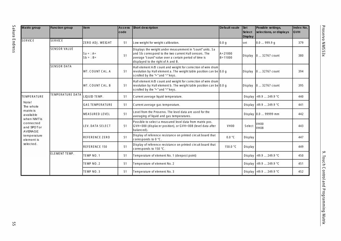
Sakura E
ndress
55
Proservo N
MS
53x9. Touch C
ontrol and P
rogram
ming
Matrix
Matrix group Function group Item Accesscode
Short description Default vaule SetSelectDisplay
Possible settings,selections, or displays
Index No,GVH
SERVICE SERVICEZERO ADJ. WEIGHT 51 Low weight for weight calibration. 0.0 g set 0.0 ... 999.9 g 379
SENSOR VALUE
Sa = : A=Sb = : B=
51
Displays the weight under measurement in "count" units. Saand Sb correspond to the two current Hall sensors. Theaverage "count" value over a certain period of time isdisplayed to the right of A and B.
A=21000B=11000
Display 0 ... 32767 count 380
SENSOR DATA
WT. COUNT CAL. A 51Hall element A/D count and weight for correction of wire drumrevolution by Hall element a. The weight table position can bescrolled by the "+" and "-" keys.
0.0 g Display 0 ... 32767 count 394
WT. COUNT CAL. B 51Hall element A/D count and weight for correction of wire drumrevolution by Hall element b. The weight table position can bescrolled by the "+" and "-" keys.
0.0 g Display 0 ... 32767 count 395
TEMPERATURETEMPERATURE DATA
LIQUID TEMP. 51 Current average liquid temperature. Display -49.9 ... 249.9 °C 440
GAS TEMPERATURE 51 Current average gas temperature. Display -49.9 ... 249.9 °C 441
MEASURED LEVEL 51Level from the Proservo. The level data are used for theaveraging of liquid and gas temperatures.
Display 0.0 ... 99999 mm 442
LEV. DATA SELECT 51Possible to select a measured level data from matrix pos.GVH=000 (displacer position), or GVH=008 (level data afterbalanced).
VH00 SelectVH00VH08
443
REFERENCE ZERO 51Display of reference resistance on printed circuit board thatcorresponds to 0 °C.
0.0 °C Display 447
REFERENCE 150 51Display of reference resistance on printed circuit board thatcorresponds to 150 °C.
150.0 °C Display 449
ELEMENT TEMP.TEMP NO. 1 51 Temperature of element No. 1 (deepest point) Display -49.9 ... 249.9 °C 450
TEMP NO. 2 51 Temperature of element No. 2 Display -49.9 ... 249.9 °C 451
TEMP NO. 3 51 Temperature of element No. 3 Display -49.9 ... 249.9 °C 452
Note!The wholematrix isava ilab lewhen NMTisc onnec tedand SPOTorAVERAGEtempera tureelement isselec ted .
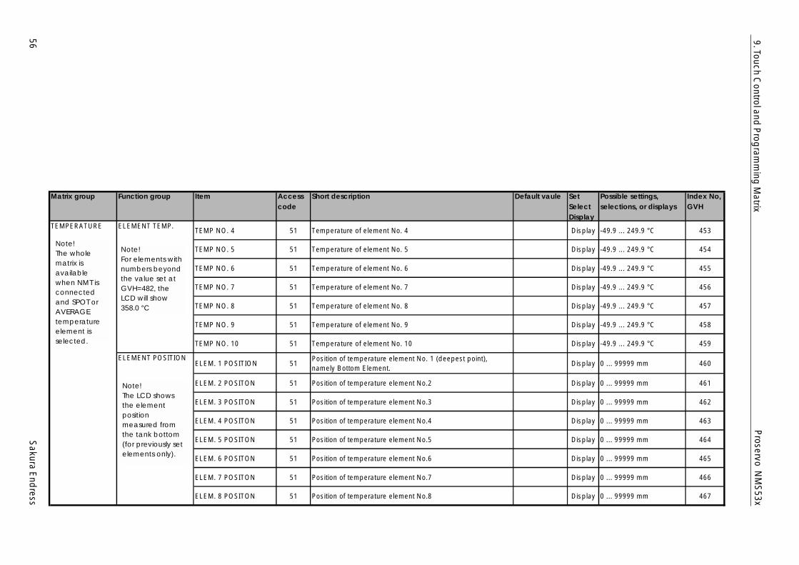
56S
akura End
ress
Proservo N
MS
53x9. Touch C
ontrol and P
rogram
ming
Matrix
Matrix group Function group Item Accesscode
Short description Default vaule SetSelectDisplay
Possible settings,selections, or displays
Index No,GVH
TEMPERATURE ELEMENT TEMP.TEMP NO. 4 51 Temperature of element No. 4 Display -49.9 ... 249.9 °C 453
TEMP NO. 5 51 Temperature of element No. 5 Display -49.9 ... 249.9 °C 454
TEMP NO. 6 51 Temperature of element No. 6 Display -49.9 ... 249.9 °C 455
TEMP NO. 7 51 Temperature of element No. 7 Display -49.9 ... 249.9 °C 456
TEMP NO. 8 51 Temperature of element No. 8 Display -49.9 ... 249.9 °C 457
TEMP NO. 9 51 Temperature of element No. 9 Display -49.9 ... 249.9 °C 458
TEMP NO. 10 51 Temperature of element No. 10 Display -49.9 ... 249.9 °C 459
ELEMENT POSITIONELEM. 1 POSITION 51
Position of temperature element No. 1 (deepest point),namely Bottom Element.
Display 0 ... 99999 mm 460
ELEM. 2 POSITON 51 Position of temperature element No.2 Display 0 ... 99999 mm 461
ELEM. 3 POSITON 51 Position of temperature element No.3 Display 0 ... 99999 mm 462
ELEM. 4 POSITON 51 Position of temperature element No.4 Display 0 ... 99999 mm 463
ELEM. 5 POSITON 51 Position of temperature element No.5 Display 0 ... 99999 mm 464
ELEM. 6 POSITON 51 Position of temperature element No.6 Display 0 ... 99999 mm 465
ELEM. 7 POSITON 51 Position of temperature element No.7 Display 0 ... 99999 mm 466
ELEM. 8 POSITON 51 Position of temperature element No.8 Display 0 ... 99999 mm 467
Note!For elements w ithnumbers beyondthe va lue set a tGVH=482, theLCD will show358.0 °C
Note!The LCD showsthe elementpositionmeasured fromthe tank bottom(for previously setelements only).
Note!The wholematrix isava ilab lewhen NMTisconnec tedand SPOTorAVERAGEtempera tureelement isselec ted .
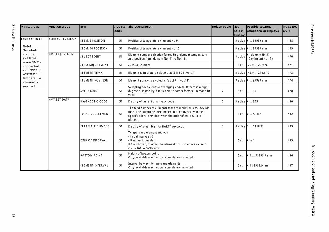
Sakura E
ndress
57
Proservo N
MS
53x9. Touch C
ontrol and P
rogram
ming
Matrix
Matrix group Function group Item Accesscode
Short description Default vaule SetSelectDisplay
Possible settings,selections, or displays
Index No,GVH
TEMPERATURE ELEMENT POSITIONELEM. 9 POSITON 51 Position of temperature element No.9 Display 0 ... 99999 mm 468
ELEM. 10 POSITION 51 Position of temperature element No.10 Display 0 ... 99999 mm 469
NMT ADJUSTMENTSELECT POINT 51
Element number selection for reading element temperatureand position from element No. 11 to No. 16.
Display0 (element No.1)10 (element No.11)
470
ZERO ADJUSTMENT 51 Zero adjustment Set -20.0 ... 20.0 °C 471
ELEMENT TEMP. 51 Element temperature selected at "SELECT POINT" Display -49.9 ... 249.9 °C 473
ELEMENT POSITION 51 Element position selected at "SELECT POINT" Display 0 ... 99999 mm 474
AVERAGING 51Sampling coefficient for averaging of data. If there is a highdegree of instability due to noise or other factors, increase istvalue.
2 Set 1 ... 10 478
NMT SET DATADIAGNOSTIC CODE 51 Display of current diagnostic code. 0 Display 0 ... 255 480
TOTAL NO. ELEMENT 51
The total number of elements that are mounted in the flexibletube. This number is determined in accordance with thespecifications provided when the order of the device isplaced.
Set a ... A HEX 482
PREAMBLE NUMBER 51 Display of preambles for HART® protocol. 5 Display 2 ... 14 HEX 483
KIND OF INTERVAL 51
Temperature element intervals.- Equal intervals: 0- Unequal intervals: 1If 1 is chosen, then set the element position on matrix fromGVH=460 to GVH=469.
Set 0 or 1 485
BOTTOM POINT 51Height of bottom point.Only available when equal intervals are selected.
Set 0.0 ... 99999.9 mm 486
ELEMENT INTERVAL 51Interval between temperature elements.Only available when equal intervals are selected.
Set 0.0 99999.9 mm 487
Note!The wholematrix isava ilab lewhen NMTisconnec tedand SPOTorAVERAGEtempera tureelement isselec ted .
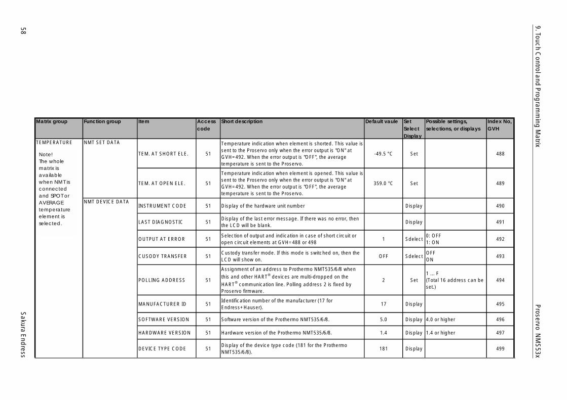
58S
akura End
ress
Proservo N
MS
53x9. Touch C
ontrol and P
rogram
ming
Matrix
Matrix group Function group Item Accesscode
Short description Default vaule SetSelectDisplay
Possible settings,selections, or displays
Index No,GVH
TEMPERATURE NMT SET DATA
TEM. AT SHORT ELE. 51
Temperature indication when element is shorted. This value issent to the Proservo only when the error output is "ON" atGVH=492. When the error output is "OFF", the averagetemperature is sent to the Proservo.
-49.5 °C Set 488
TEM. AT OPEN ELE. 51
Temperature indication when element is opened. This value issent to the Proservo only when the error output is "ON" atGVH=492. When the error output is "OFF", the averagetemperature is sent to the Proservo.
359.0 °C Set 489
NMT DEVICE DATAINSTRUMENT CODE 51 Display of the hardware unit number Display 490
LAST DIAGNOSTIC 51Display of the last error message. If there was no error, thenthe LCD will be blank.
Display 491
OUTPUT AT ERROR 51Selection of output and indication in case of short circuit oropen circuit elements at GVH=488 or 498
1 Sdelect0: OFF1: ON
492
CUSODY TRANSFER 51Custody transfer mode. If this mode is switched on, then theLCD will show on.
OFF SdelectOFFON
493
POLLING ADDRESS 51
Assignment of an address to Prothermo NMT535/6/8 whenthis and other HART® devices are multi-dropped on theHART® communication line. Polling address 2 is fixed byProservo firmware.
2 Set1 ... F(Total 16 address can beset.)
494
MANUFACTURER ID 51Identification number of the manufacturer (17 forEndress+Hauser).
17 Display 495
SOFTWARE VERSION 51 Software version of the Prothermo NMT535/6/8. 5.0 Display 4.0 or higher 496
HARDWARE VERSION 51 Hardware version of the Prothermo NMT535/6/8. 1.4 Display 1.4 or higher 497
DEVICE TYPE CODE 51Display of the device type code (181 for the ProthermoNMT535/6/8).
181 Display 499
Note!The wholematrix isava ilab lewhen NMTisc onnec tedand SPOTorAVERAGEtempera tureelement isselec ted .
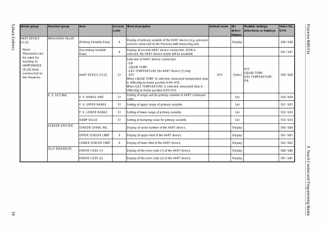
Sakura E
ndress
59
Proservo N
MS
53x9. Touch C
ontrol and P
rogram
ming
Matrix
Matrix group Function group Item Accesscode
Short description Default vaule SetSelectDisplay
Possible settings,selections, or displays
Index No,GVH
HART DEVICE(1) (2)
MEASURED VALUE(Primary Variable Data) 0
Display of primary variable of the HART device (e.g. pressuresensor) connected to the Proservo with measuring unit.
Display 540 / 640
(Secondary VariableData)
0Display of second HART device connection. If ON isselected, the HART device matrix will be available.
541 / 641
HART DEVICE (1) (2) 51
Selection of HART device connection.- ON- LIQUID TEMP.- GAS TEMPERATURE (for HART device (1) only- OFFWhen LIQUID TEMP. Is selected, measured temperature datais reflecting to matrix position GVH=010.When GAS TEMPERATURE is selected, measured data isreflecting to matrix position GVH=013
OFF Select
OFFLIQUID TEMP.GAS TEMPERATUREON
549 / 649
P. V. SETTING P. V. RANGE UNIT 51Setting of range unit for primary variable in HART commandcode.
Set 550 / 650
P. V. UPPER RANGE 51 Setting of upper range of primary variable. Set 551 / 651
P. V. LOWER RANGE 51 Setting of lower range of primary variable. Set 552 / 652
DAMP VALUE 51 Setting of damping value for primary variable. Set 553 / 653
SENSOR SPECIFICSENSOR SERIAL NO. Display of serial number of the HART device. Display 560 / 660
UPPER SENSOR LIMIT 0 Display of upper limit of the HART device. Display 561 / 661
LOWER SENSOR LIMIT 0 Display of lower limit of the HART device. Display 562 / 662
SELF DIAGNOSISERROR CODE (1) Display of the error code (1) of the HART device. Display 580 / 680
ERROR CODE (2) Display of the error code (2) of the HART device. Display 581 / 681
Note!This matrix canbe used forread ing ofHARTDEVICE(1) (2) dataconnec ted tothe Proservo.
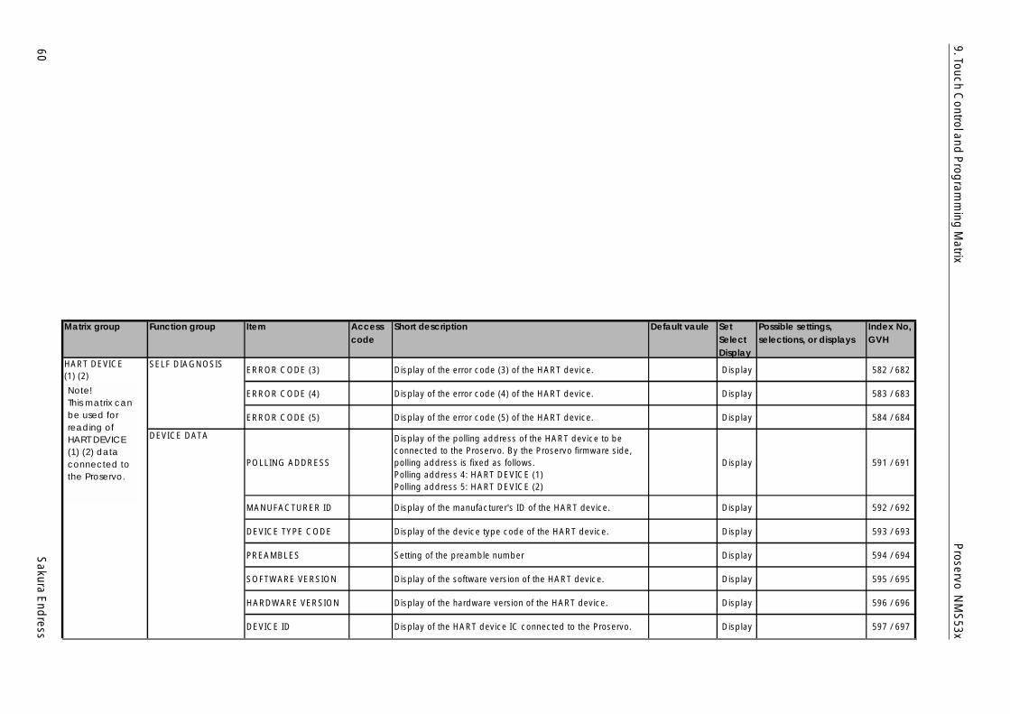
60S
akura End
ress
Proservo N
MS
53x9. Touch C
ontrol and P
rogram
ming
Matrix
Matrix group Function group Item Accesscode
Short description Default vaule SetSelectDisplay
Possible settings,selections, or displays
Index No,GVH
HART DEVICE(1) (2)
SELF DIAGNOSISERROR CODE (3) Display of the error code (3) of the HART device. Display 582 / 682
ERROR CODE (4) Display of the error code (4) of the HART device. Display 583 / 683
ERROR CODE (5) Display of the error code (5) of the HART device. Display 584 / 684
DEVICE DATA
POLLING ADDRESS
Display of the polling address of the HART device to beconnected to the Proservo. By the Proservo firmware side,polling address is fixed as follows.Polling address 4: HART DEVICE (1)Polling address 5: HART DEVICE (2)
Display 591 / 691
MANUFACTURER ID Display of the manufacturer's ID of the HART device. Display 592 / 692
DEVICE TYPE CODE Display of the device type code of the HART device. Display 593 / 693
PREAMBLES Setting of the preamble number Display 594 / 694
SOFTWARE VERSION Display of the software version of the HART device. Display 595 / 695
HARDWARE VERSION Display of the hardware version of the HART device. Display 596 / 696
DEVICE ID Display of the HART device IC connected to the Proservo. Display 597 / 697
Note!This matrix c anbe used forread ing ofHARTDEVICE(1) (2) dataconnec ted tothe Proservo.
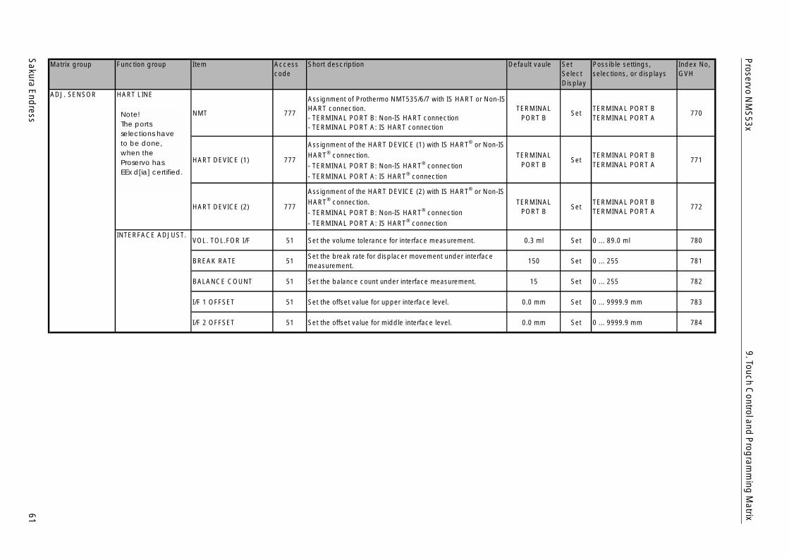
Sakura E
ndress
61
Proservo N
MS
53x9. Touch C
ontrol and P
rogram
ming
Matrix
Matrix group Function group Item Accesscode
Short description Default vaule SetSelectDisplay
Possible settings,selections, or displays
Index No,GVH
ADJ. SENSOR HART LINE
NMT 777
Assignment of Prothermo NMT535/6/7 with IS HART or Non-ISHART connection.- TERMINAL PORT B: Non-IS HART connection- TERMINAL PORT A: IS HART connection
TERMINALPORT B
SetTERMINAL PORT BTERMINAL PORT A
770
HART DEVICE (1) 777
Assignment of the HART DEVICE (1) with IS HART® or Non-ISHART® connection.- TERMINAL PORT B: Non-IS HART® connection- TERMINAL PORT A: IS HART® connection
TERMINALPORT B
SetTERMINAL PORT BTERMINAL PORT A
771
HART DEVICE (2) 777
Assignment of the HART DEVICE (2) with IS HART® or Non-ISHART® connection.- TERMINAL PORT B: Non-IS HART® connection- TERMINAL PORT A: IS HART® connection
TERMINALPORT B
SetTERMINAL PORT BTERMINAL PORT A
772
INTERFACE ADJUST.VOL. TOL.FOR I/F 51 Set the volume tolerance for interface measurement. 0.3 ml Set 0 ... 89.0 ml 780
BREAK RATE 51Set the break rate for displacer movement under interfacemeasurement.
150 Set 0 ... 255 781
BALANCE COUNT 51 Set the balance count under interface measurement. 15 Set 0 ... 255 782
I/F 1 OFFSET 51 Set the offset value for upper interface level. 0.0 mm Set 0 ... 9999.9 mm 783
I/F 2 OFFSET 51 Set the offset value for middle interface level. 0.0 mm Set 0 ... 9999.9 mm 784
Note!The portsselec tions haveto be done,when theProservo hasEEx d [ia ] c ertified .
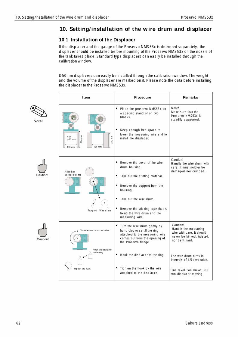
62 Sakura Endress
Proservo NMS53x10. Setting/installation of the wire drum and displacer
10.1 Installation of the DisplacerIf the displacer and the gauge of the Proservo NMS53x is delivered separately, thedisplacer should be installed before mounting of the Proservo NMS53x on the nozzle ofthe tank takes place. Standard type displacers can easily be installed through thecalibration window.
Ø50mm displacers can easily be installed through the calibration window. The weightand the volume of the displacer are marked on it. Please note the data before installingthe displacer to the Proservo NMS53x.
Item Procedure Remarks
• Place the proservo NMS53x ona spacing stand or on twoblocks.
• Keep enough free space tolower the measuring wire and toinstall the displacer.
• Remove the cover of the wiredrum housing.
• Take out the stuffing material.
• Remove the support from thehousing.
• Take out the wire drum.
• Remove the sticking tape that isfixing the wire drum and themeasuring wire.
• Turn the wire drum gently byhand clockwise till the ringattached to the measuring wirecomes out from the opening ofthe Proservo flange.
• Hook the displacer to the ring.
• Tighten the hook by the wireattached to the displacer.
Note!Make sure that theProservo NMS53x issteadily supported.
Caution!Handle the wire drum withcare. It must neither bedamaged nor crimped.
Caution!Handle the measuringwire with care. It shouldnever be kinked, twisted,nor bent hard.
The wire drum turns inintervals of 1/5 revolution.
One revolution draws 300mm displacer moving.
Holeφ 70 mm
130 mm 130 mm
200
mm
200
mm
Support Wire drum
Allen hexsocket bolt M6
Tighten the hook
Turn the wire drum clockwise
Hook the displacerto the ring
10. Setting/installation of the wire drum and displacer
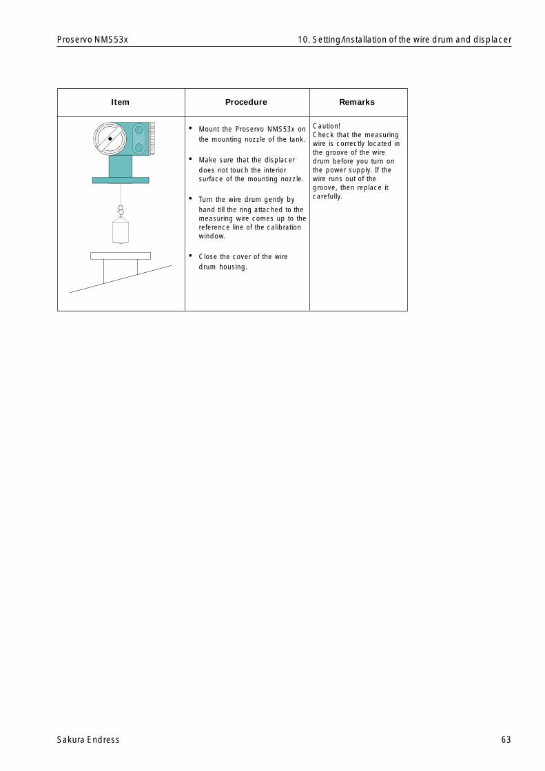
Sakura Endress 63
Proservo NMS53x
Item Procedure Remarks
Caution!Check that the measuringwire is correctly located inthe groove of the wiredrum before you turn onthe power supply. If thewire runs out of thegroove, then replace itcarefully.
• Mount the Proservo NMS53x onthe mounting nozzle of the tank.
• Make sure that the displacerdoes not touch the interiorsurface of the mounting nozzle.
• Turn the wire drum gently byhand till the ring attached to themeasuring wire comes up to thereference line of the calibrationwindow.
• Close the cover of the wiredrum housing.
10. Setting/installation of the wire drum and displacer
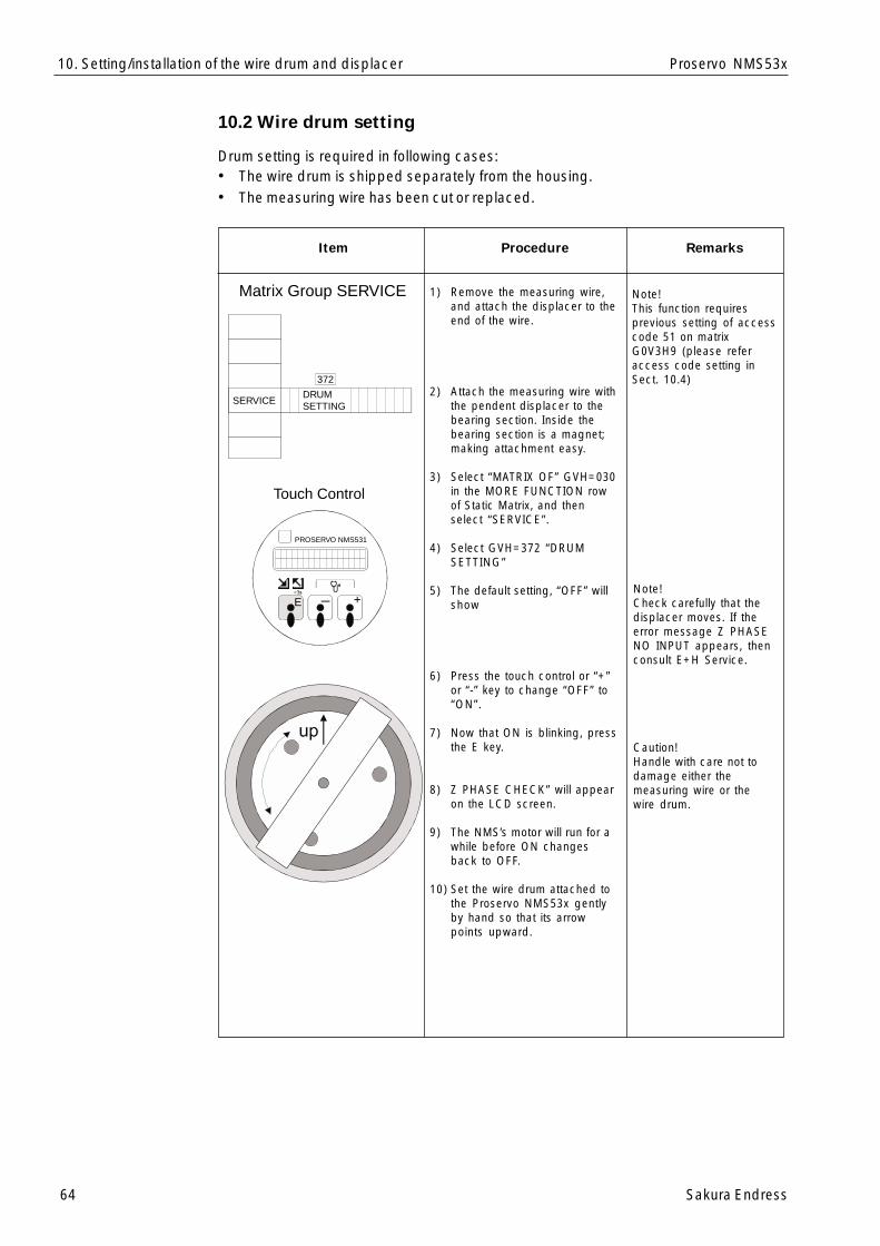
64 Sakura Endress
Proservo NMS53x
10.2 Wire drum setting
Drum setting is required in following cases:• The wire drum is shipped separately from the housing.• The measuring wire has been cut or replaced.
Item
1) Remove the measuring wire,and attach the displacer to theend of the wire.
2) Attach the measuring wire withthe pendent displacer to thebearing section. Inside thebearing section is a magnet;making attachment easy.
3) Select “MATRIX OF” GVH=030in the MORE FUNCTION rowof Static Matrix, and thenselect “SERVICE”.
4) Select GVH=372 “DRUMSETTING”
5) The default setting, “OFF” willshow
6) Press the touch control or “+”or “-” key to change “OFF” to“ON”.
7) Now that ON is blinking, pressthe E key.
8) Z PHASE CHECK” will appearon the LCD screen.
9) The NMS’s motor will run for awhile before ON changesback to OFF.
10) Set the wire drum attached tothe Proservo NMS53x gentlyby hand so that its arrowpoints upward.
Procedure Remarks
Note!This function requiresprevious setting of accesscode 51 on matrixG0V3H9 (please referaccess code setting inSect. 10.4)
Caution!Handle with care not todamage either themeasuring wire or thewire drum.
Note!Check carefully that thedisplacer moves. If theerror message Z PHASENO INPUT appears, thenconsult E+H Service.
Matrix Group SERVICE
SERVICEDRUMSETTING
372
Touch Control
PROSERVO NMS531
E_ +
10. Setting/installation of the wire drum and displacer
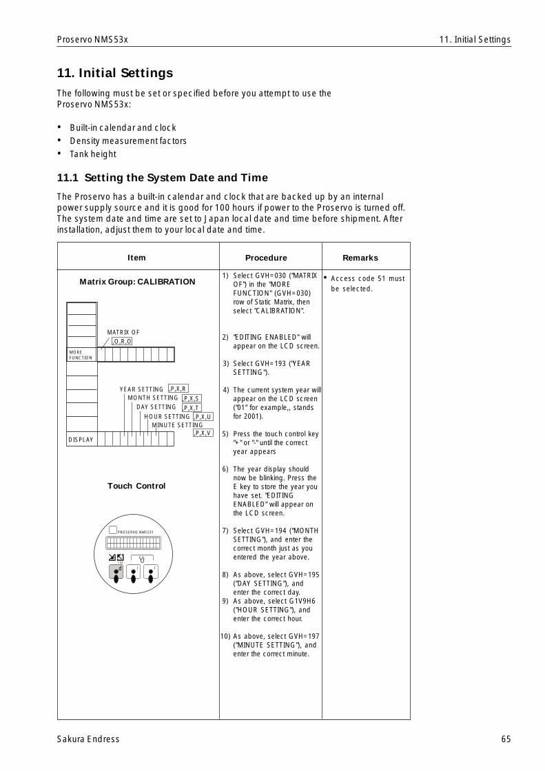
Sakura Endress 65
Proservo NMS53x
Item
Matrix Group: CALIBRATION
Touch Control
RemarksProcedure
11. Initial Settings
The following must be set or specified before you attempt to use theProservo NMS53x:
• Built-in calendar and clock• Density measurement factors• Tank height
11.1 Setting the System Date and Time
The Proservo has a built-in calendar and clock that are backed up by an internalpower supply source and it is good for 100 hours if power to the Proservo is turned off.The system date and time are set to Japan local date and time before shipment. Afterinstallation, adjust them to your local date and time.
1) Select GVH=030 ("MATRIXOF") in the "MOREFUNCTION" (GVH=030)row of Static Matrix, thenselect "CALIBRATION".
2) "EDITING ENABLED" willappear on the LCD screen.
3) Select GVH=193 ("YEARSETTING").
4) The current system year willappear on the LCD screen("01" for example,, standsfor 2001).
5) Press the touch control key"+" or "-" until the correctyear appears
6) The year display shouldnow be blinking. Press theE key to store the year youhave set. "EDITINGENABLED" will appear onthe LCD screen.
7) Select GVH=194 ("MONTHSETTING"), and enter thecorrect month just as youentered the year above.
8) As above, select GVH=195("DAY SETTING"), andenter the correct day.
9) As above, select G1V9H6("HOUR SETTING"), andenter the correct hour.
10) As above, select GVH=197("MINUTE SETTING"), andenter the correct minute.
YEAR SETTINGMONTH SETTING
DAY SETTING
HOUR SETTINGMINUTE SETTING
DISPLAY
MATRIX OF
MOREFUNCTION
‚O‚R‚O
‚P‚X‚R
‚P‚X‚S‚P‚X‚T
‚P‚X‚U
‚P‚X‚V
{|‚d>3s
PROSERVO NMS531
• Access code 51 mustbe selected.
11. Initial Settings

66 Sakura Endress
Proservo NMS53x
Item
Static Matrix
Touch Control
RemarksProcedure
1) Select function GVH=005of the Static Matrix todisplay the "UPPERDENSITY".
2) Using the "+" and "-"keys, enter the valueexpressing the correctdensity,, then press the"E" key to confirm theentry.
3) "EDITING ENABLED" willappear on the LCDscreen.
{|‚d>3s
PROSERVO NMS531
• Access code 51 must beselected.
11.2 Initial Settings of Density Measurement
UPPER DENSITY(Density of the
Upper Liquid Layer)
MEASUREDVALUE 1
005
If the liquid is layered,, thefollowing steps must alsobe performed.
1) Select GVH=006 of StaticMatrix to display the"MIDDLE DENSITY".
2) Using the "+" and "-" keys,enter the valueexpressing the correctdensity of the middleliquid layer. Press the "E"key to confirm the entry.
3) As above, selectGVH=007 "LOWERDENSITY" and enter thedensity value of the lowerliquid layer.
The interfacial measurementrequires that the correctdensity of the middle andlower layers be entered. Thedensity value is updatedwhen the Proservo measuresthe density.
Static Matrix
MIDDLE DENSITY(Density of the MiddleLiquid Layer)
MEASUREDVALUE 1
LOWER DENSITY(Density of the Lower
Liquid Layer)
0 0 7
0 0 6
11. Initial Settings
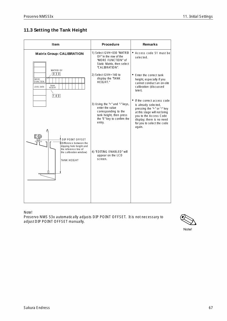
Sakura Endress 67
Proservo NMS53x 11. Initial Settings
Item
Matrix Group: CALIBRATION
RemarksProcedure
1) Select GVH=030 "MATRIXOF" in the row of the"MORE FUNCTION" ofStatic Matrix, then select"CALIBRATION".
2) Select GVH=140 todisplay the "TANKHEIGHT."
3) Using the "+" and "-" keys,enter the valuecorresponding to thetank height, then pressthe "E" key to confirm theentry.
4) "EDITING ENABLED" willappear on the LCDscreen.
LEVEL DATATANK
HEIGHT
MOREFUNCTION
MATRIX OF
1 4 0
0 3 0
PROSERVO
E | {
TANK HEIGHT
DIP POINT OFFSET(Difference between thedipping hole height andthe reference line ofthe calibration window)
• Access code 51 must beselected.
11.3 Setting the Tank Height
• Enter the correct tankheight, especially if youcannot conduct an on-sitecalibration (discussedlater).
• If the correct access codeis already selected,pressing the "+" or "-" keyat this stage will not bringyou to the Access Codedisplay; there is no needfor you to select the codeagain.
Note!Proservo NMS 53x automatically adjusts DIP POINT OFFSET. It is not necessary toadjust DIP POINT OFFSET manually.

68 Sakura Endress
Proservo NMS53x
12. Initial Weight Calibration
12.1 Displacer Weight Calibration
Weight table calibration must be done after Hall sensor adjustment. Use this procedurefor NMS 53x with level measurement function only.
Note! Wind and vibration affect weight table calibration.
Item RemarksProcedure
12. Initial Calibration
Not necessary to make Initial Calibration for Startup “All-in-one” (displacer attached)shipments.
Weight Table calibration,Basic 1) Enter Access Code 51or higher, confirm thefollowing data.
G3V4H0 Wire DrumCircum.(engraved onwire drum)
G3V4H1 Wire Weight Standard SUS
=1.40 PTFE=4.55 Hastelloy=2.48 G3V4H2 Displacer
Weight (engraved ondisplacer)
2) Displacer is incalibration window ormaintenance chamber
Set Operation=STOP Set G3V7H3 Weight
Calib.=ON At ”Low weight set?”
enter Yes (+)
At ”Displacer Down?” for calibration window,
enter NO (-) for maintenance
chamber, enter Yes (+)
e.g.300.110
e.g.250.2 g
HV
0 1 2
4 xxx.xxx x.xx xxx.x
ServiceMatrix: G3
Wire Drum Displacer
1.
530ACCESS CODE
e.g.
+
+
-STOPOPERATION
ONWEIGHT CALIB.
Low weight set: ok?
Displacer down?
2.
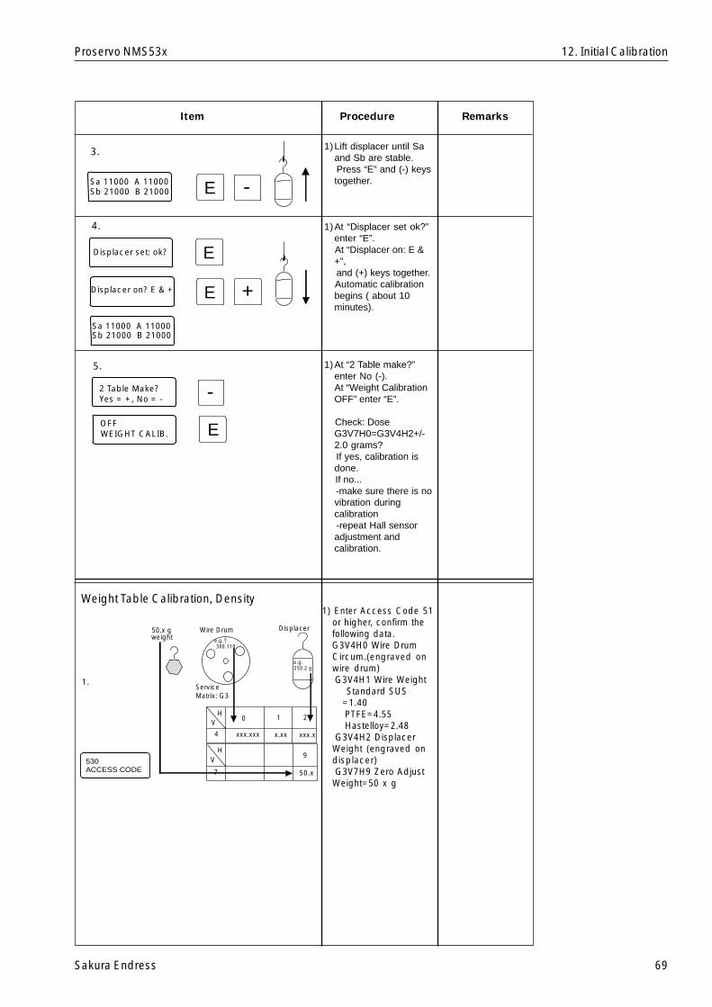
Sakura Endress 69
Proservo NMS53x
-E
E
E +
-
Sa 11000 A 11000Sb 21000 B 21000
Displacer set: ok?
Displacer on? E & +
Sa 11000 A 11000Sb 21000 B 21000
2 Table Make?Yes = +, No = -
OFFWEIGHT CALIB. E
3.
4.
5.
1)Lift displacer until Saand Sb are stable.
Press “E” and (-) keystogether.
1)At “Displacer set ok?”enter “E”.
At “Displacer on: E &+”,
and (+) keys together. Automatic calibration
begins ( about 10minutes).
1)At “2 Table make?”enter No (-).
At “Weight CalibrationOFF” enter “E”.
Check: DoseG3V7H0=G3V4H2+/-2.0 grams?
If yes, calibration isdone.
If no... -make sure there is no
vibration duringcalibration
-repeat Hall sensoradjustment andcalibration.
Item RemarksProcedure
12. Initial Calibration
Weight Table Calibration, Density1) Enter Access Code 51
or higher, confirm thefollowing data.
G3V4H0 Wire DrumCircum.(engraved onwire drum)
G3V4H1 Wire Weight Standard SUS
=1.40 PTFE=4.55 Hastelloy=2.48 G3V4H2 Displacer
Weight (engraved ondisplacer)
G3V7H9 Zero AdjustWeight=50 x g
e.g.300.110
e.g.250.2 g
HV
0 1 2
4 xxx.xxx x.xx xxx.x
ServiceMatrix: G3
Wire Drum Displacer
1.
530ACCESS CODE
HV
7
9
50.x
50.x gweight
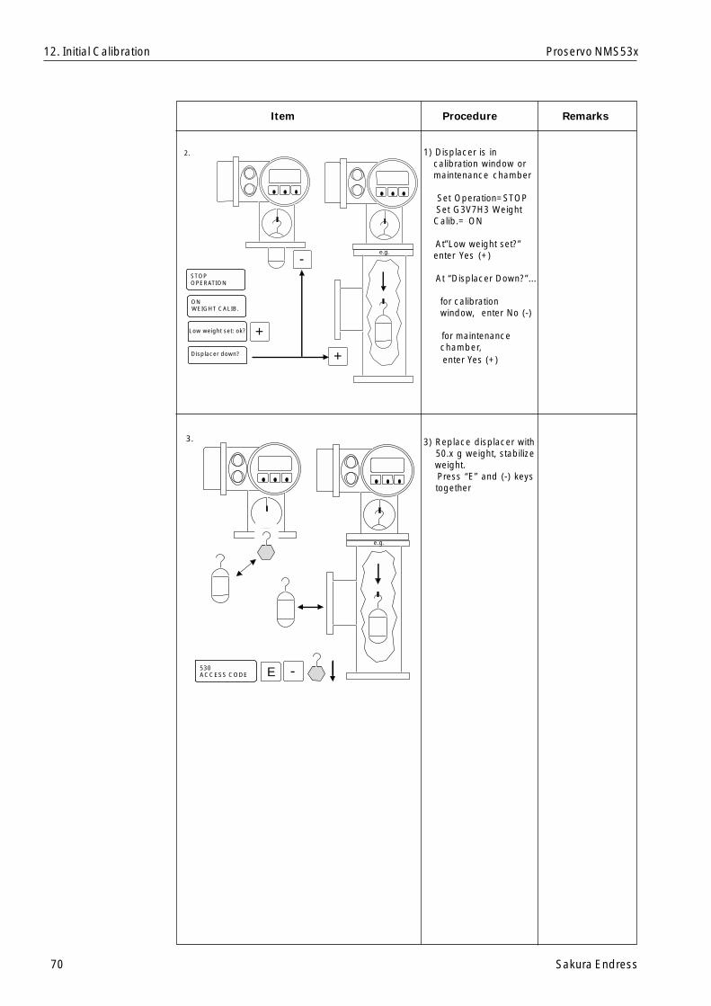
70 Sakura Endress
Proservo NMS53x
Item RemarksProcedure
1) Displacer is incalibration window ormaintenance chamber
Set Operation=STOP Set G3V7H3 Weight
Calib.= ON
At”Low weight set?”enter Yes (+)
At “Displacer Down?”...
for calibrationwindow, enter No (-)
for maintenancechamber,
enter Yes (+)
3) Replace displacer with 50.x g weight, stabilize weight. Press “E” and (-) keys together
12. Initial Calibration
e.g.
+
+
-STOPOPERATION
ONWEIGHT CALIB.
Low weight set: ok?
Displacer down?
2.
e.g.
3.
530ACCESS CODE -E

Sakura Endress 71
Proservo NMS53x
e.g.
4.
-E
EDisplacer set: ok?
Displacer on: E & +
Sa 21000 A 21000Sb 11000 B 11000
Item RemarksProcedure
1) Replace displacer onwire.
At “Displacer set ok?”enter “E”.
AT “Displacer on: E &+”, press “E” and (+)keys together.
Automatic calibrationbegins (about 10minutes).
1) At “2 Table Make?enter No (-).
At “Weight CalibrationOFF” enter “E”.
Check: Dose G3V7H2+/- 2.0 grams?
If yes, calibration isdone.
If no... -make sure there is no
vibration duringcalibration
-repeat Hall sensoradjustment andcalibration
12. Initial Calibration
-
E
2 Table Make?Yes = +, No = -
OFFWEIGHT CALIB.
5.
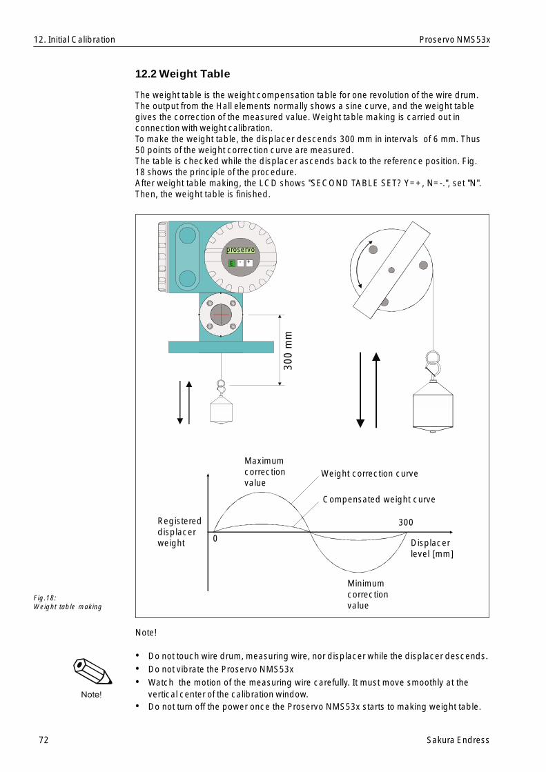
72 Sakura Endress
Proservo NMS53x
12.2 Weight Table
The weight table is the weight compensation table for one revolution of the wire drum.The output from the Hall elements normally shows a sine curve, and the weight tablegives the correction of the measured value. Weight table making is carried out inconnection with weight calibration.To make the weight table, the displacer descends 300 mm in intervals of 6 mm. Thus50 points of the weight correction curve are measured.The table is checked while the displacer ascends back to the reference position. Fig.18 shows the principle of the procedure.After weight table making, the LCD shows "SECOND TABLE SET? Y=+, N=-.", set "N".Then, the weight table is finished.
Note!
• Do not touch wire drum, measuring wire, nor displacer while the displacer descends.• Do not vibrate the Proservo NMS53x• Watch the motion of the measuring wire carefully. It must move smoothly at the
vertical center of the calibration window.• Do not turn off the power once the Proservo NMS53x starts to making weight table.
12. Initial Calibration
Fig.18:Weight table making
300
mm
Maximumcorrectionvalue
Weight correction curve
Compensated weight curve
300
Displacerlevel [mm]
Minimumcorrectionvalue
Registereddisplacerweight
proservo
E - +
0

Sakura Endress 73
Proservo NMS53x
Item RemarksProcedure
13. Operation of the Displacer
The operation of the displacer for level, bottom level, interface level, and densitymeasurement is possible by touch control.
Static Matrix 1)Select function groupGVH=020 OPERATION.
2)Select item OPERATION.The LCD shows thecommand given to theProservo NMS53x andthe displacer position.
The following commandsare available at thisposition:
LEVELUPSTOPBOTTOM LEVELUPPER INTERF.LEV*MIDD.INTERF.LEV*MIDDLE DENSITY*DENSITY BOTTOM*WATER DIP*REPEATABILITY TEST
* Interface and densitymeasurements are notavailable unlessspecifically requested.
• Set access code to 50.
• If editing has previouslybeen enabled by a validaccess code, then therequest for the code willnot appear.
• The optional operationcommands are availablewhen such options areset.
• Density measurement isdescribed in AppendixC.
13. Operation of the Displacer
OPERATION OPERATION
Touch Control
PROSERVO NMS531
proservo
E - +
LevelDensity
Interfacelevel
Bottomlevel
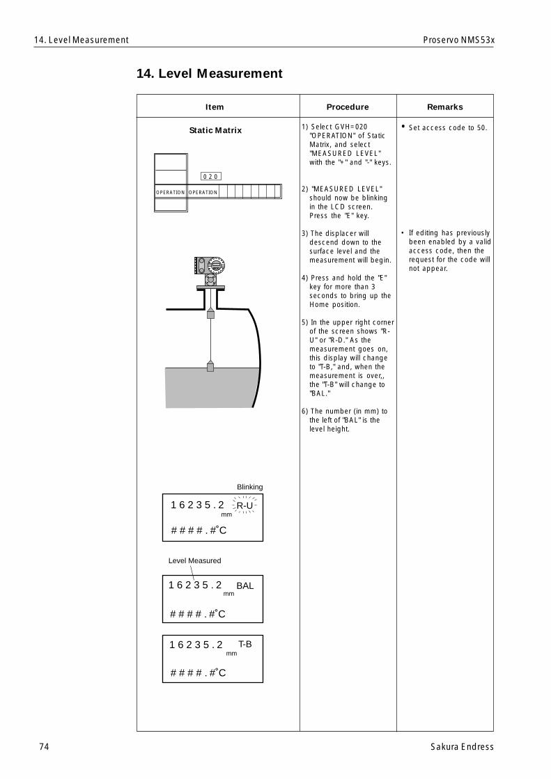
74 Sakura Endress
Proservo NMS53x
14. Level Measurement
Item RemarksProcedure
1) Select GVH=020"OPERATION" of StaticMatrix, and select"MEASURED LEVEL"with the "+" and "-" keys.
2) "MEASURED LEVEL"should now be blinkingin the LCD screen.Press the "E" key.
3) The displacer willdescend down to thesurface level and themeasurement will begin.
4) Press and hold the "E"key for more than 3seconds to bring up theHome position.
5) In the upper right cornerof the screen shows "R-U" or "R-D." As themeasurement goes on,this display will changeto "T-B," and, when themeasurement is over,,the "T-B" will change to"BAL."
6) The number (in mm) tothe left of "BAL" is thelevel height.
• Set access code to 50.
• If editing has previouslybeen enabled by a validaccess code, then therequest for the code willnot appear.
14. Level Measurement
Static Matrix
Blinking
Level Measured
1 6 2 3 5 . 2 R-U
# # # # . #˚C
# # # # . #˚C
# # # # . #˚C
1 6 2 3 5 . 2 BAL
1 6 2 3 5 . 2 T-B
mm
mm
mm
PROSERVO
E +
OPERATION OPERATION
0 2 0
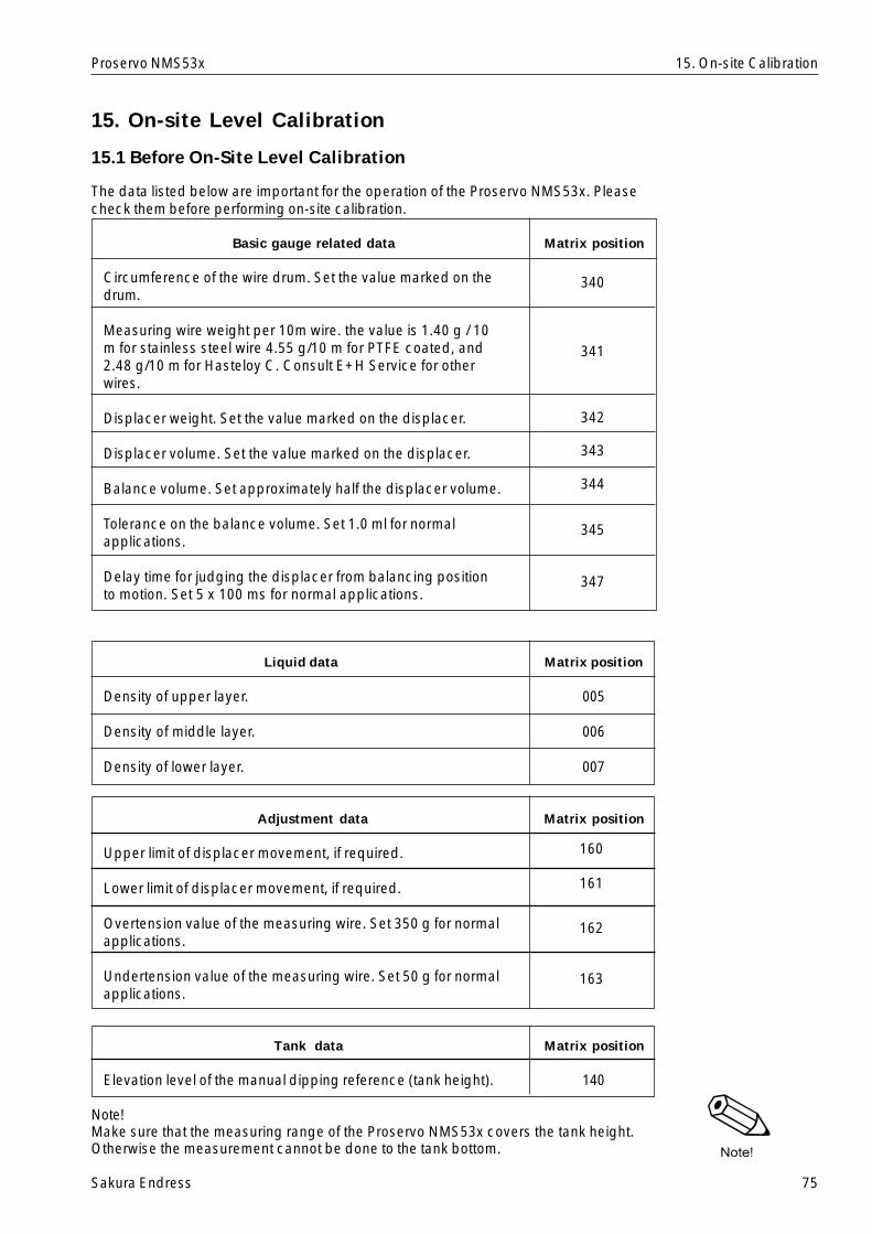
Sakura Endress 75
Proservo NMS53x
15. On-site Level Calibration
15.1 Before On-Site Level Calibration
The data listed below are important for the operation of the Proservo NMS53x. Pleasecheck them before performing on-site calibration.
Basic gauge related data Matrix position
Circumference of the wire drum. Set the value marked on thedrum.
Measuring wire weight per 10m wire. the value is 1.40 g / 10m for stainless steel wire 4.55 g/10 m for PTFE coated, and2.48 g/10 m for Hasteloy C. Consult E+H Service for otherwires.
Displacer weight. Set the value marked on the displacer.
Displacer volume. Set the value marked on the displacer.
Balance volume. Set approximately half the displacer volume.
Tolerance on the balance volume. Set 1.0 ml for normalapplications.
Delay time for judging the displacer from balancing positionto motion. Set 5 x 100 ms for normal applications.
Liquid data Matrix position
Density of upper layer. 005
Density of middle layer. 006
Density of lower layer. 007
Adjustment data Matrix position
Upper limit of displacer movement, if required.
Lower limit of displacer movement, if required.
Overtension value of the measuring wire. Set 350 g for normalapplications.
Undertension value of the measuring wire. Set 50 g for normalapplications.
Tank data Matrix position
Elevation level of the manual dipping reference (tank height). 140
Note!Make sure that the measuring range of the Proservo NMS53x covers the tank height.Otherwise the measurement cannot be done to the tank bottom.
15. On-site Calibration
340
341
342
343
344
345
347
160
161
162
163
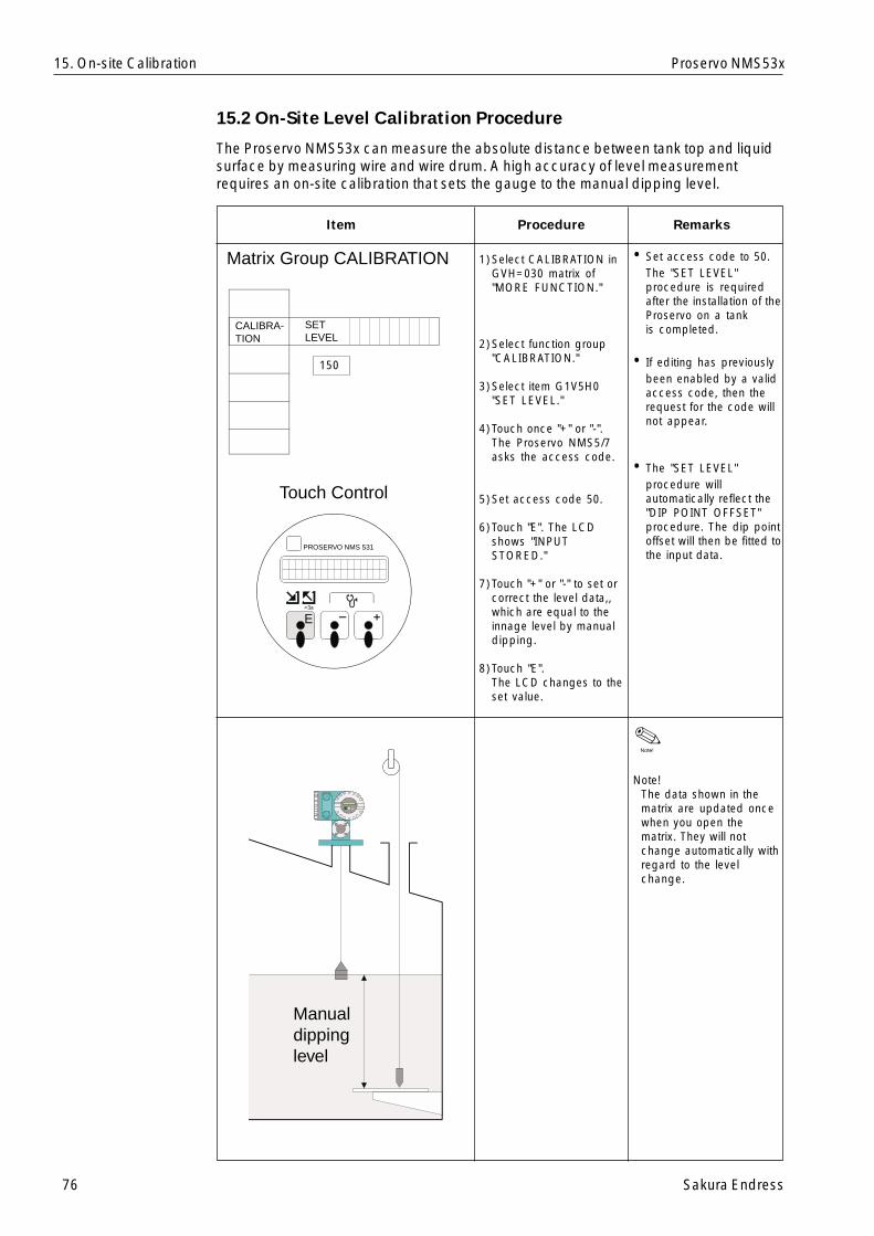
76 Sakura Endress
Proservo NMS53x
Matrix Group CALIBRATION
Touch Control
PROSERVO NMS 531
SETLEVEL
CALIBRA-TION
15. On-site Calibration
15.2 On-Site Level Calibration Procedure
The Proservo NMS53x can measure the absolute distance between tank top and liquidsurface by measuring wire and wire drum. A high accuracy of level measurementrequires an on-site calibration that sets the gauge to the manual dipping level.
Item RemarksProcedure
1)Select CALIBRATION inGVH=030 matrix of"MORE FUNCTION."
2)Select function group"CALIBRATION."
3)Select item G1V5H0"SET LEVEL."
4)Touch once "+" or "-".The Proservo NMS5/7asks the access code.
5)Set access code 50.
6)Touch "E". The LCDshows "INPUTSTORED."
7)Touch "+" or "-" to set orcorrect the level data,,which are equal to theinnage level by manualdipping.
8)Touch "E".The LCD changes to theset value.
Note!The data shown in thematrix are updated oncewhen you open thematrix. They will notchange automatically withregard to the levelchange.
• Set access code to 50.The "SET LEVEL"procedure is requiredafter the installation of theProservo on a tankis completed.
• If editing has previouslybeen enabled by a validaccess code, then therequest for the code willnot appear.
• The "SET LEVEL"procedure willautomatically reflect the"DIP POINT OFFSET"procedure. The dip pointoffset will then be fitted tothe input data.
150
Manualdippinglevel
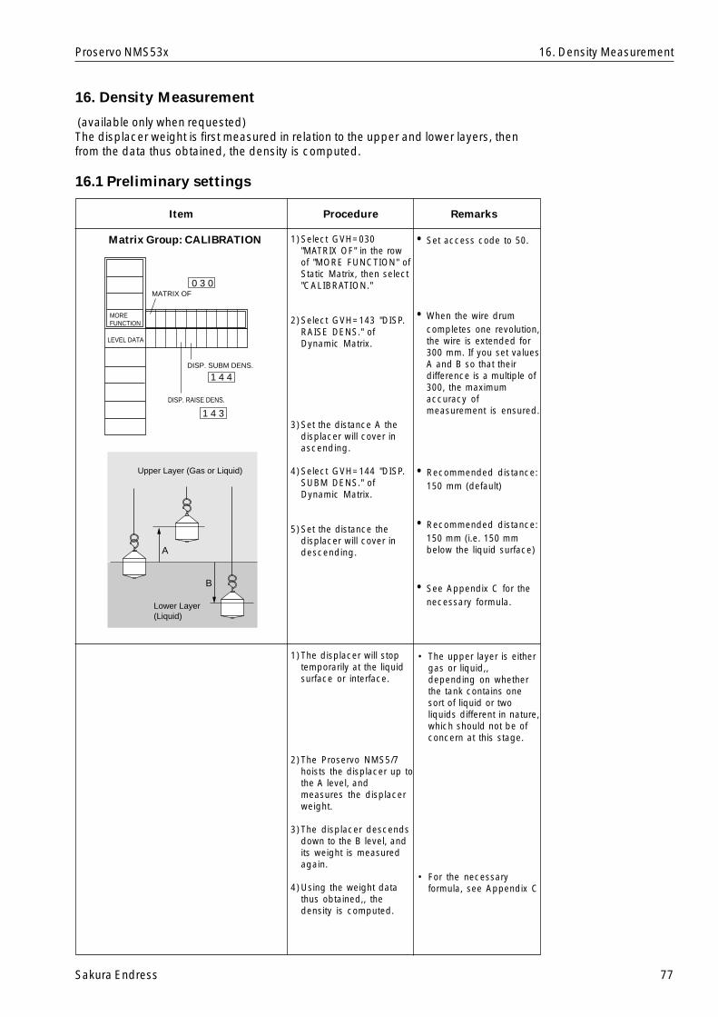
Sakura Endress 77
Proservo NMS53x
16. Density Measurement
(available only when requested)The displacer weight is first measured in relation to the upper and lower layers, thenfrom the data thus obtained, the density is computed.
16.1 Preliminary settings
Item RemarksProcedure
Matrix Group: CALIBRATION 1)Select GVH=030"MATRIX OF" in the rowof "MORE FUNCTION" ofStatic Matrix, then select"CALIBRATION."
2)Select GVH=143 "DISP.RAISE DENS." ofDynamic Matrix.
3)Set the distance A thedisplacer will cover inascending.
4)Select GVH=144 "DISP.SUBM DENS." ofDynamic Matrix.
5)Set the distance thedisplacer will cover indescending.
• Set access code to 50.
• When the wire drumcompletes one revolution,the wire is extended for300 mm. If you set valuesA and B so that theirdifference is a multiple of300, the maximumaccuracy ofmeasurement is ensured.
• Recommended distance:150 mm (default)
• Recommended distance:150 mm (i.e. 150 mmbelow the liquid surface)
• See Appendix C for thenecessary formula.
1)The displacer will stoptemporarily at the liquidsurface or interface.
2)The Proservo NMS5/7hoists the displacer up tothe A level, andmeasures the displacerweight.
3)The displacer descendsdown to the B level, andits weight is measuredagain.
4)Using the weight datathus obtained,, thedensity is computed.
• The upper layer is eithergas or liquid,,depending on whetherthe tank contains onesort of liquid or twoliquids different in nature,which should not be ofconcern at this stage.
• For the necessaryformula, see Appendix C
16. Density Measurement
Upper Layer (Gas or Liquid)
Lower Layer(Liquid)
A
B
LEVEL DATA
DISP. SUBM DENS.
DISP. RAISE DENS.
MATRIX OF
MOREFUNCTION
0 3 0
1 4 4
1 4 3
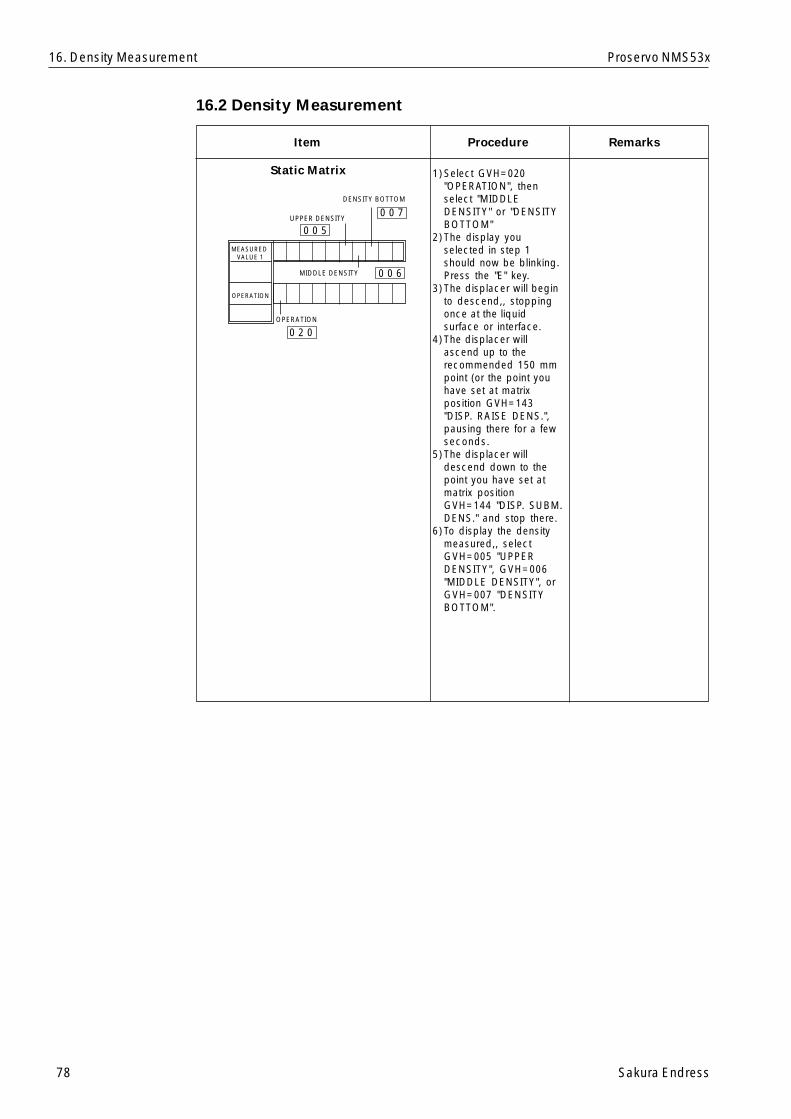
78 Sakura Endress
Proservo NMS53x
16.2 Density Measurement
Item RemarksProcedure
Static Matrix 1)Select GVH=020"OPERATION", thenselect "MIDDLEDENSITY" or "DENSITYBOTTOM"
2)The display youselected in step 1should now be blinking.Press the "E" key.
3)The displacer will beginto descend,, stoppingonce at the liquidsurface or interface.
4)The displacer willascend up to therecommended 150 mmpoint (or the point youhave set at matrixposition GVH=143"DISP. RAISE DENS.",pausing there for a fewseconds.
5)The displacer willdescend down to thepoint you have set atmatrix positionGVH=144 "DISP. SUBM.DENS." and stop there.
6)To display the densitymeasured,, selectGVH=005 "UPPERDENSITY", GVH=006"MIDDLE DENSITY", orGVH=007 "DENSITYBOTTOM".
16. Density Measurement
OPERATION
UPPER DENSITY
MIDDLE DENSITY
MEASURED VALUE 1
OPERATION
DENSITY BOTTOM
0 0 5
0 0 7
0 0 6
0 2 0
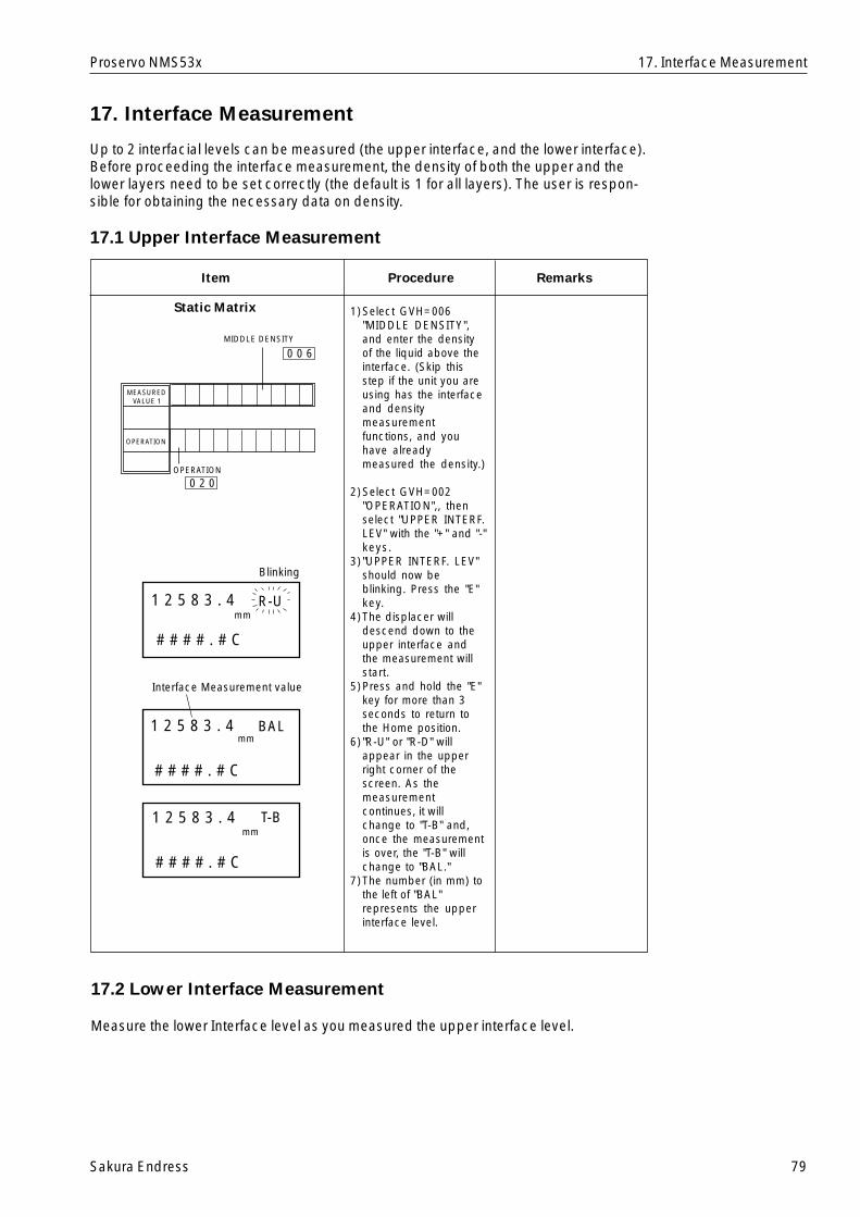
Sakura Endress 79
Proservo NMS53x
17. Interface Measurement
Up to 2 interfacial levels can be measured (the upper interface, and the lower interface).Before proceeding the interface measurement, the density of both the upper and thelower layers need to be set correctly (the default is 1 for all layers). The user is respon-sible for obtaining the necessary data on density.
17.1 Upper Interface Measurement
Item RemarksProcedure
Static Matrix 1)Select GVH=006"MIDDLE DENSITY",and enter the densityof the liquid above theinterface. (Skip thisstep if the unit you areusing has the interfaceand densitymeasurementfunctions, and youhave alreadymeasured the density.)
2)Select GVH=002"OPERATION",, thenselect "UPPER INTERF.LEV" with the "+" and "-"keys.
3) "UPPER INTERF. LEV"should now beblinking. Press the "E"key.
4)The displacer willdescend down to theupper interface andthe measurement willstart.
5)Press and hold the "E"key for more than 3seconds to return tothe Home position.
6) "R-U" or "R-D" willappear in the upperright corner of thescreen. As themeasurementcontinues, it willchange to "T-B" and,once the measurementis over, the "T-B" willchange to "BAL."
7)The number (in mm) tothe left of "BAL"represents the upperinterface level.
17.2 Lower Interface Measurement
Measure the lower Interface level as you measured the upper interface level.
17. Interface Measurement
0 0 6
0 2 0
MIDDLE DENSITY
OPERATION
MEASURED VALUE 1
OPERATION
Blinking
Interface Measurement value
1 2 5 8 3 . 4 R-U
# # # # . # C
# # # # . # C
# # # # . # C
BAL
T-B
mm
mm
mm
1 2 5 8 3 . 4
1 2 5 8 3 . 4
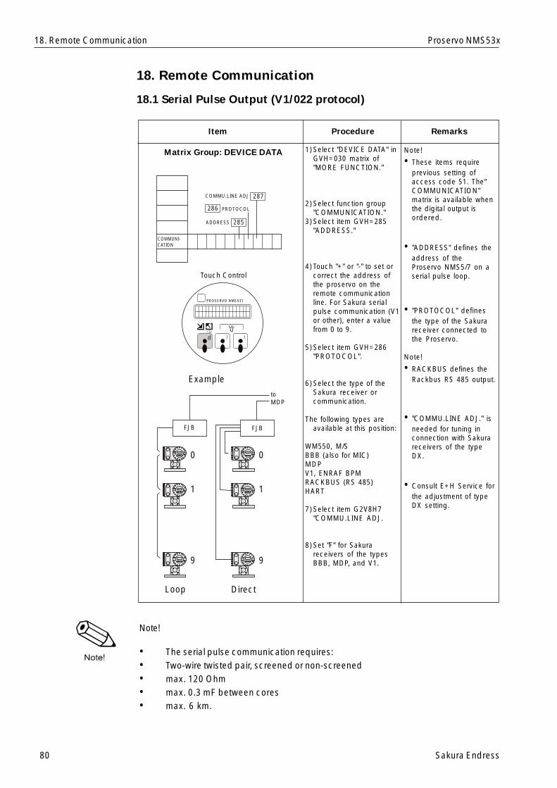
80 Sakura Endress
Proservo NMS53x
18. Remote Communication
18.1 Serial Pulse Output (V1/022 protocol)
Item RemarksProcedure
Matrix Group: DEVICE DATA 1)Select "DEVICE DATA" inGVH=030 matrix of"MORE FUNCTION."
2)Select function group"COMMUNICATION."
3)Select item GVH=285"ADDRESS."
4)Touch "+" or "-" to set orcorrect the address ofthe proservo on theremote communicationline. For Sakura serialpulse communication (V1or other), enter a valuefrom 0 to 9.
5)Select item GVH=286"PROTOCOL".
6)Select the type of theSakura receiver orcommunication.
The following types areavailable at this position:
WM550, M/SBBB (also for MIC)MDPV1, ENRAF BPMRACKBUS (RS 485)HART
7)Select item G2V8H7"COMMU.LINE ADJ.
8)Set "F" for Sakurareceivers of the typesBBB, MDP, and V1.
Note!
• These items requireprevious setting ofaccess code 51. The"COMMUNICATION"matrix is available whenthe digital output isordered.
• "ADDRESS" defines theaddress of theProservo NMS5/7 on aserial pulse loop.
• "PROTOCOL" definesthe type of the Sakurareceiver connected tothe Proservo.
Note!
• RACKBUS defines theRackbus RS 485 output.
• "COMMU.LINE ADJ." isneeded for tuning inconnection with Sakurareceivers of the typeDX.
• Consult E+H Service forthe adjustment of typeDX setting.
Note!
• The serial pulse communication requires:• Two-wire twisted pair, screened or non-screened• max. 120 Ohm• max. 0.3 mF between cores• max. 6 km.
18. Remote Communication
{|d>3s
PROSERVO NMS531
Touch Control
PROSERVO
E | {
COMMUNI-CATION
PROSERVO
E | {
PROSERVO
E | {
0
1
9
PROSERVO
E | {
PROSERVO
E | {
PROSERVO
E | {
0
1
9
toMDP
Example
ADDRESS
PROTOCOL
COMMU.LINE ADJ
FJBFJB
287
285
286
Loop Direct
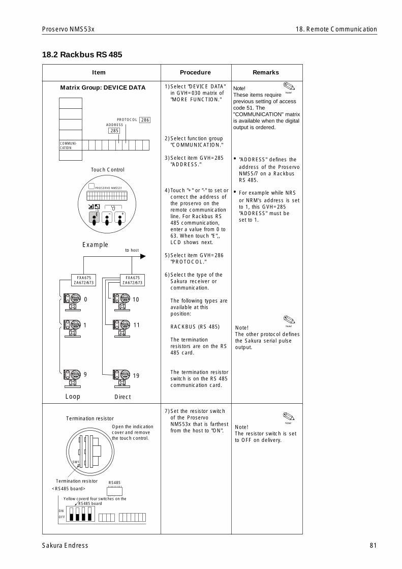
Sakura Endress 81
Proservo NMS53x
18.2 Rackbus RS 485
Item RemarksProcedure
Matrix Group: DEVICE DATA 1)Select "DEVICE DATA"in GVH=030 matrix of"MORE FUNCTION."
2)Select function group"COMMUNICATION."
3)Select item GVH=285"ADDRESS."
4)Touch "+" or "-" to set orcorrect the address ofthe proservo on theremote communicationline. For Rackbus RS485 communication,enter a value from 0 to63. When touch "E",,LCD shows next.
5)Select item GVH=286"PROTOCOL."
6)Select the type of theSakura receiver orcommunication.
The following types areavailable at thisposition:
RACKBUS (RS 485)
The terminationresistors are on the RS485 card.
The termination resistorswitch is on the RS 485communication card.
7)Set the resistor switchof the ProservoNMS53x that is farthestfrom the host to "ON".
Note!These items requireprevious setting of accesscode 51. The"COMMUNICATION" matrixis available when the digitaloutput is ordered.
• "ADDRESS" defines theaddress of the ProservoNMS5/7 on a RackbusRS 485.
• For example while NRSor NRM's address is setto 1, this GVH=285"ADDRESS" must beset to 1.
Note!The other protocol definesthe Sakura serial pulseoutput.
Note!The resistor switch is setto OFF on delivery.
18. Remote Communication
>3s
PROSERVO NMS531
Touch Control
PROSERVO
E | {
COMMUNI-CATION
PROSERVO
E | {
PROSERVO
E | {
PROSERVO
E | {
PROSERVO
E | {
PROSERVO
E | {
toExample
ADDRESSPROTOCOL
285
286
Loop
E - +
host
FXA675ZA672/673
FXA675ZA672/673
0
1
9
10
11
19
Direct
Termination resistor
Termination resistor
Open the indication cover and remove the touch control.
<RS485 board>
Yellow coverd four switches on the RS485 board
RS485
ON
OFF
SW1
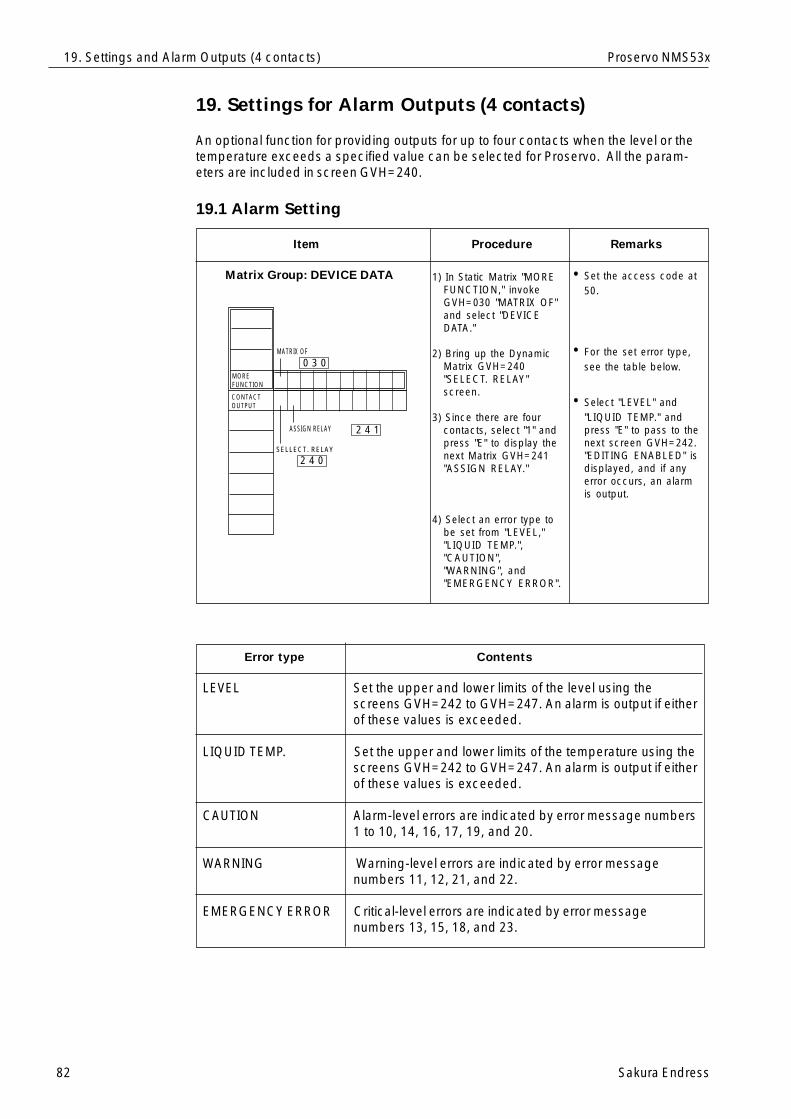
82 Sakura Endress
Proservo NMS53x
19. Settings for Alarm Outputs (4 contacts)
An optional function for providing outputs for up to four contacts when the level or thetemperature exceeds a specified value can be selected for Proservo. All the param-eters are included in screen GVH=240.
19.1 Alarm Setting
Item RemarksProcedure
Matrix Group: DEVICE DATA 1) In Static Matrix "MOREFUNCTION," invokeGVH=030 "MATRIX OF"and select "DEVICEDATA."
2) Bring up the DynamicMatrix GVH=240"SELECT. RELAY"screen.
3) Since there are fourcontacts, select "1" andpress "E" to display thenext Matrix GVH=241"ASSIGN RELAY."
4) Select an error type tobe set from "LEVEL,""LIQUID TEMP.","CAUTION","WARNING", and"EMERGENCY ERROR".
• Set the access code at50.
• For the set error type,see the table below.
• Select "LEVEL" and"LIQUID TEMP." andpress "E" to pass to thenext screen GVH=242."EDITING ENABLED" isdisplayed, and if anyerror occurs, an alarmis output.
Error type Contents
LEVEL Set the upper and lower limits of the level using thescreens GVH=242 to GVH=247. An alarm is output if eitherof these values is exceeded.
LIQUID TEMP. Set the upper and lower limits of the temperature using thescreens GVH=242 to GVH=247. An alarm is output if eitherof these values is exceeded.
CAUTION Alarm-level errors are indicated by error message numbers1 to 10, 14, 16, 17, 19, and 20.
WARNING Warning-level errors are indicated by error messagenumbers 11, 12, 21, and 22.
EMERGENCY ERROR Critical-level errors are indicated by error messagenumbers 13, 15, 18, and 23.
19. Settings and Alarm Outputs (4 contacts)
CONTACT OUTPUT
SELLECT. RELAY
ASSIGN RELAY
MOREFUNCTION
MATRIX OF
0 3 0
2 4 1
2 4 0
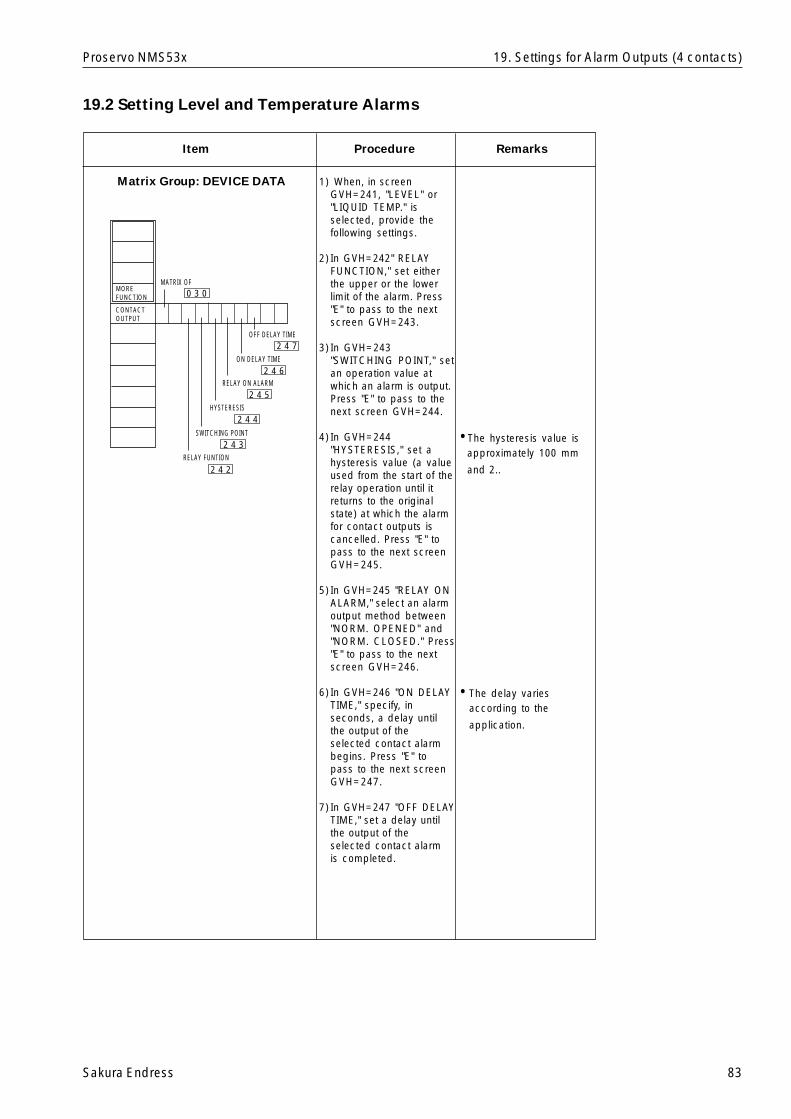
Sakura Endress 83
Proservo NMS53x 19. Settings for Alarm Outputs (4 contacts)
19.2 Setting Level and Temperature Alarms
Item RemarksProcedure
Matrix Group: DEVICE DATA 1) When, in screenGVH=241, "LEVEL" or"LIQUID TEMP." isselected, provide thefollowing settings.
2) In GVH=242" RELAYFUNCTION," set eitherthe upper or the lowerlimit of the alarm. Press"E" to pass to the nextscreen GVH=243.
3) In GVH=243"SWITCHING POINT," setan operation value atwhich an alarm is output.Press "E" to pass to thenext screen GVH=244.
4) In GVH=244"HYSTERESIS," set ahysteresis value (a valueused from the start of therelay operation until itreturns to the originalstate) at which the alarmfor contact outputs iscancelled. Press "E" topass to the next screenGVH=245.
5) In GVH=245 "RELAY ONALARM," select an alarmoutput method between"NORM. OPENED" and"NORM. CLOSED." Press"E" to pass to the nextscreen GVH=246.
6) In GVH=246 "ON DELAYTIME," specify, inseconds, a delay untilthe output of theselected contact alarmbegins. Press "E" topass to the next screenGVH=247.
7) In GVH=247 "OFF DELAYTIME," set a delay untilthe output of theselected contact alarmis completed.
•The hysteresis value isapproximately 100 mm
and 2..
•The delay variesaccording to the
application.
OFF DELAY TIME
ON DELAY TIME
RELAY ON ALARM
HYSTERESIS
SWITCHING POINT
RELAY FUNTION
MOREFUNCTION
CONTACTOUTPUT
MATRIX OF0 3 0
2 4 7
2 4 6
2 4 5
2 4 4
2 4 3
2 4 2
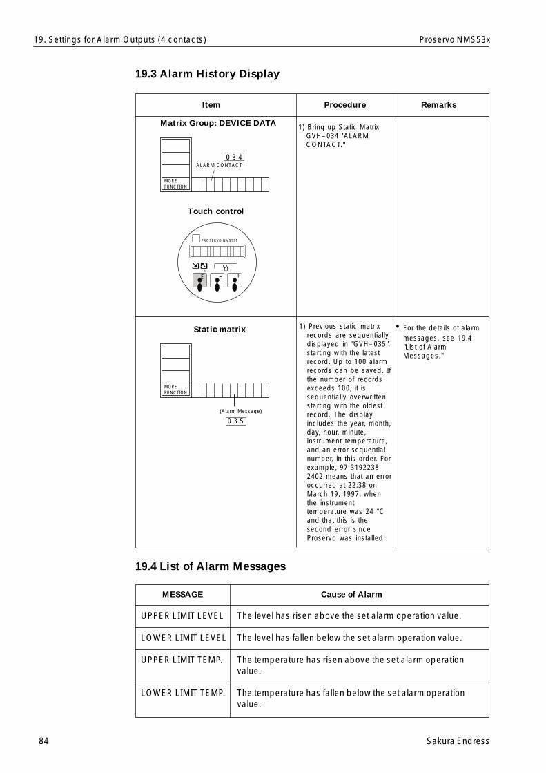
84 Sakura Endress
Proservo NMS53x19. Settings for Alarm Outputs (4 contacts)
Item RemarksProcedure
Matrix Group: DEVICE DATA 1) Bring up Static MatrixGVH=034 "ALARMCONTACT."
• For the details of alarmmessages, see 19.4"List of AlarmMessages."
19.3 Alarm History Display
1) Previous static matrixrecords are sequentiallydisplayed in "GVH=035",starting with the latestrecord. Up to 100 alarmrecords can be saved. Ifthe number of recordsexceeds 100, it issequentially overwrittenstarting with the oldestrecord. The displayincludes the year, month,day, hour, minute,instrument temperature,and an error sequentialnumber, in this order. Forexample, 97 31922382402 means that an erroroccurred at 22:38 onMarch 19, 1997, whenthe instrumenttemperature was 24 °Cand that this is thesecond error sinceProservo was installed.
Touch control
Static matrix
19.4 List of Alarm Messages
MESSAGE Cause of Alarm
UPPER LIMIT LEVEL The level has risen above the set alarm operation value.
LOWER LIMIT LEVEL The level has fallen below the set alarm operation value.
UPPER LIMIT TEMP. The temperature has risen above the set alarm operationvalue.
LOWER LIMIT TEMP. The temperature has fallen below the set alarm operationvalue.
+-E>3s
PROSERVO NMS531
ALARM CONTACT
MOREFUNCTION
0 3 4
(Alarm Message)
MOREFUNCTION
0 3 5
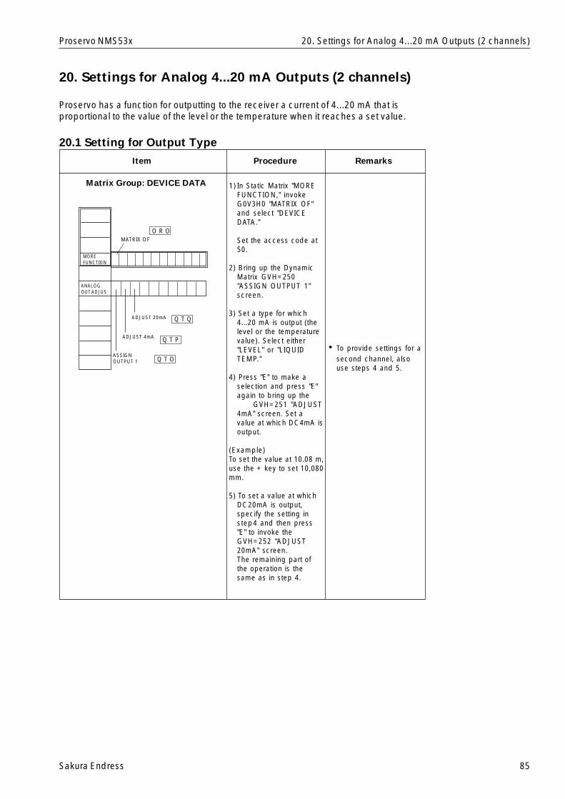
Sakura Endress 85
Proservo NMS53x
Item RemarksProcedure
Matrix Group: DEVICE DATA
• To provide settings for asecond channel, alsouse steps 4 and 5.
20. Settings for Analog 4...20 mA Outputs (2 channels)
Proservo has a function for outputting to the receiver a current of 4...20 mA that isproportional to the value of the level or the temperature when it reaches a set value.
20.1 Setting for Output Type
1) In Static Matrix "MOREFUNCTION," invokeG0V3H0 "MATRIX OF"and select "DEVICEDATA."
Set the access code at50.
2) Bring up the DynamicMatrix GVH=250"ASSIGN OUTPUT 1"screen.
3) Set a type for which4...20 mA is output (thelevel or the temperaturevalue). Select either"LEVEL" or "LIQUIDTEMP."
4) Press "E" to make aselection and press "E"again to bring up the
GVH=251 "ADJUST4mA" screen. Set avalue at which DC4mA isoutput.
(Example)To set the value at 10.08 m,use the + key to set 10,080mm.
5) To set a value at whichDC20mA is output,specify the setting instep4 and then press"E" to invoke theGVH=252 "ADJUST20mA" screen.The remaining part ofthe operation is thesame as in step 4.
20. Settings for Analog 4...20 mA Outputs (2 channels)
ANALOGOUT.ADJUS
ASSIGNOUTPUT 1
ADJUST 4mA
Q T O
Q T P
ADJUST 20mA Q T Q
MOREFUNCTION
O R OMATRIX OF

86 Sakura Endress
Proservo NMS53x20. Settings for Analog 4...20 mA Outputs (2 channels)
Item RemarksProcedure
Matrix Group: DEVICE DATA
• HOLD: When an erroroccurs, the current valueof the output current isfixed and will notrespond to changes inlevel or temperature.MAX: When an erroroccurs, a 20 mA currentis output instead of thecurrent output current.MIN: When an erroroccurs, a 4 mA currentis output instead of thecurrent output current.OFF: No special currentis output when an erroroccurs.
20.2 Settings for Current Output When Error Occurs
6) Next, set the currentoutput when an erroroccurs. Press "E" tobring up the MatrixGVH=256 "DEVICE ATALARM screen.
7) On the screen, select acurrent type from"HOLD," "MAX," and"MIN."
DEVICE AT ALARM
MOREFUNCTION
ANALOGOUT.ADJUS
2 5 6
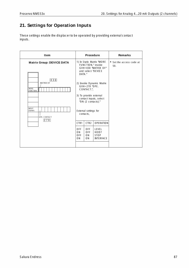
Sakura Endress 87
Proservo NMS53x 20. Settings for Analog 4...20 mA Outputs (2 channels)
Item RemarksProcedure
Matrix Group: DEVICE DATA • Set the access code at50.
21. Settings for Operation Inputs
These settings enable the displacer to be operated by providing external contactinputs.
1) In Static Matrix "MOREFUNCTION," invokeGVH=030 "MATRIX OF"and select "DEVICEDATA."
2) Invoke Dynamic MatrixGVH=270 "OPE.CONTACT.",
3) To provide externalcontact inputs, select"ON (2 contacts)."
External settings forcontacts,
CTR1 CTR2 OPERATION
OFF OFF LEVELON OFF HOISTOFF ON STOPON ON INTERFACE
OPE. CONTACT
MOREFUNCTION
INPUTSIGNAL
MATRIX OF
2 7 0
0 3 0
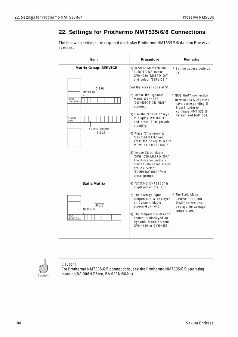
88 Sakura Endress
Proservo NMS53x
Item RemarksProcedure
Matrix Group: SERVICE • Set the access code at51.
22. Settings for Prothermo NMT535/6/8 Connections
The following settings are required to display Prothermo NMT535/6/8 data on Proservoscreens.
1) In Static Matrix "MOREFUNCTION," invokeGVH=030 "MATRIX OF"and select "SERVICE."
Set the access code at 51.
2) Invoke the DynamicMatrix GVH=362"CONNECTION NMT"screen.
3) Use the "+" and "-" keysto display "AVERAGE"and press "E" to providea setting.
4) Press "E" to return to"SYSTEM DATA" andpress the "-" key to returnto "MORE FUNCTION."
5) Invoke Static Matrix"GVH=030 MATRIX OF."The Proservo matrix isdivided into seven matrixgroups. Select"TEMPERATURE" fromthese groups.
6) "EDITING ENABLED" isdisplayed on the LCD.
7) The average liquidtemperature is displayedon Dynamic Matrixscreen GVH=440.
8) The temperature of eachcontact is displayed onDynamic Matrix screensGVH=450 to GVH=459.
22. Settings for Prothermo NMT535/6/7
• The Static MatrixGVH=010 "LIQUIDTEMP." screen alsodisplays the averagetemperature.
Static Matrix
Caution!For Prothermo NMT535/6/8 connections, see the Prothermo NMT535/6/8 operatingmanual (BA 006N/08/en, BA 020N/08/en)
CONNECTION NMT
MOREFUNCTION
SYSTEMDATA
MATRIX OF0 3 0
3 6 2
MOREFUNCTION
MATRIX OF0 3 0
• NMS HART connection (terminal 24 & 25) must have corresponding IS input in order to configure NMT 535 IS version and NMT 538.
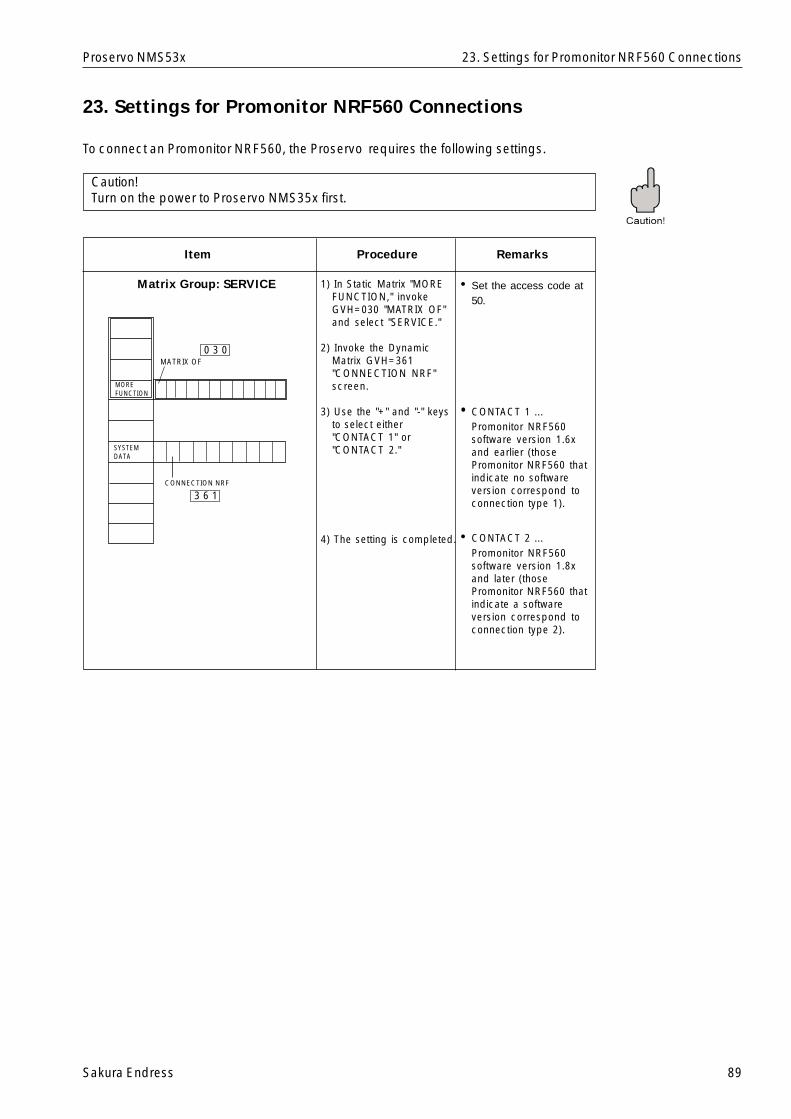
Sakura Endress 89
Proservo NMS53x
Item RemarksProcedure
Matrix Group: SERVICE • Set the access code at50.
23. Settings for Promonitor NRF560 Connections
To connect an Promonitor NRF560, the Proservo requires the following settings.
1) In Static Matrix "MOREFUNCTION," invokeGVH=030 "MATRIX OF"and select "SERVICE."
2) Invoke the DynamicMatrix GVH=361"CONNECTION NRF"screen.
3) Use the "+" and "-" keysto select either"CONTACT 1" or"CONTACT 2."
4) The setting is completed.
23. Settings for Promonitor NRF560 Connections
Caution!Turn on the power to Proservo NMS35x first.
• CONTACT 1 ...Promonitor NRF560software version 1.6xand earlier (thosePromonitor NRF560 thatindicate no softwareversion correspond toconnection type 1).
• CONTACT 2 ...Promonitor NRF560software version 1.8xand later (thosePromonitor NRF560 thatindicate a softwareversion correspond toconnection type 2).
MOREFUNCTION
SYSTEMDATA
CONNECTION NRF
MATRIX OF0 3 0
3 6 1
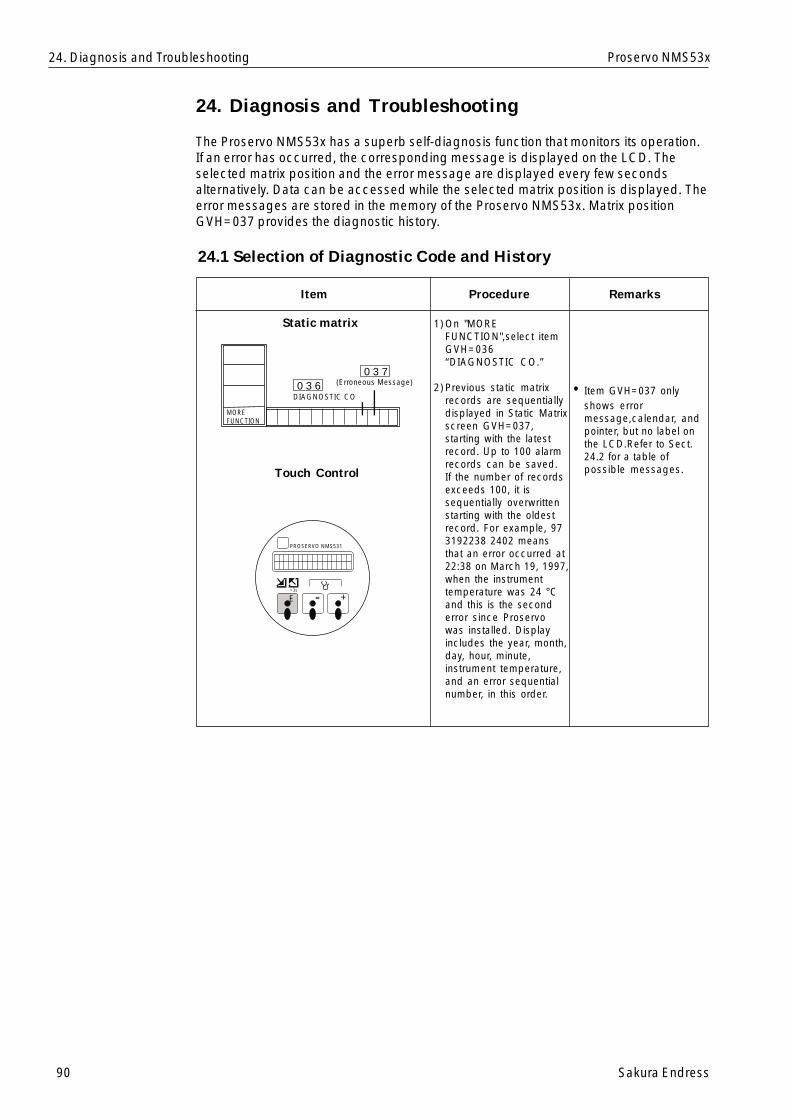
90 Sakura Endress
Proservo NMS53x
Item RemarksProcedure
Static matrix
24. Diagnosis and Troubleshooting
The Proservo NMS53x has a superb self-diagnosis function that monitors its operation.If an error has occurred, the corresponding message is displayed on the LCD. Theselected matrix position and the error message are displayed every few secondsalternatively. Data can be accessed while the selected matrix position is displayed. Theerror messages are stored in the memory of the Proservo NMS53x. Matrix positionGVH=037 provides the diagnostic history.
1)On "MOREFUNCTION",select itemGVH=036“DIAGNOSTIC CO.”
2)Previous static matrixrecords are sequentiallydisplayed in Static Matrixscreen GVH=037,starting with the latestrecord. Up to 100 alarmrecords can be saved.If the number of recordsexceeds 100, it issequentially overwrittenstarting with the oldestrecord. For example, 973192238 2402 meansthat an error occurred at22:38 on March 19, 1997,when the instrumenttemperature was 24 °Cand this is the seconderror since Proservowas installed. Displayincludes the year, month,day, hour, minute,instrument temperature,and an error sequentialnumber, in this order.
24. Diagnosis and Troubleshooting
• Item GVH=037 onlyshows errormessage,calendar, andpointer, but no label onthe LCD.Refer to Sect.24.2 for a table ofpossible messages.Touch Control
24.1 Selection of Diagnostic Code and History
+-E>3s
PROSERVO NMS531
MOREFUNCTION
DIAGNOSTIC CO
(Erroneous Message)0 3 7
0 3 6
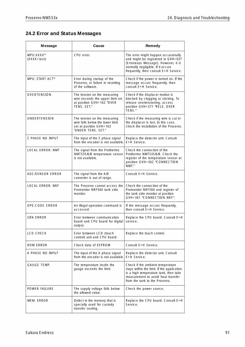
Sakura Endress 91
Proservo NMS53x
MPU:XXXX* CPU error.(XXXX=text)
MPU: START ACT* Error during startup of theProservo, or failure in resettingof the software.
OVERTENSION The tension on the measuringwire exceeds the upper limit setat position GVH=162 "OVERTENS. SET."
UNDERTENSION The tension on the measuringwire falls below the lower limitset at position GVH=163"UNDER TENS. SET."
Z PHASE NO INPUT The input of the Z phase signalfrom the encoder is not available.
LOCAL ERROR: NMT The signal from the ProthermoNMT535/6/8 temperature sensoris not available.
ADC/SENSOR ERROR The signal from the A/Dconverter is out of range.
LOCAL ERROR: NRF The Proservo cannot access thePromonitor NRF560 tank sidemonitor.
OPE.CODE ERROR An illegal operation command isaccessed.
SIFA ERROR Error between communicationboard and CPU board for digitaloutput.
LCD CHECK Error between LCD (touchcontrol) unit and CPU board.
ROM ERROR Check data of EEPROM
A PHASE NO INPUT The input of the A phase signalfrom the encoder is not available.
GAUGE TEMP. The temperature inside thegauge exceeds the limit.
POWER FAILURE The supply voltage falls belowthe allowed value.
MEM. ERROR Defect in the memory that isspecially used for custodytransfer sealing.
24.2 Error and Status Messages
24. Diagnosis and Troubleshooting
Message Cause Remedy
The error might happen occasionallyand might be registered in GVH=037(Erroneous Message). However, it isnormally negligible. If it occursfrequently, then consult E+H Service.
Check if the power is turned on. If themessage occurs frequently, thenconsult E+H Service.
Check if the displacer motion isblocked by clogging or sticking. Torelease overtensioning, accessposition GVH=371 "RELE. OVERTENS."
Check if the measuring wire is cut orthe displacer is lost. In this case,check the installation of the Proservo.
Replace the detector unit. ConsultE+H Service.
Check the connection of theProthermo NMT535/6/8. Check theregister of the temperature sensor atposition GVH=362 "CONNECTIONNMT."
Consult E+H Service.
Check the connection of thePromonitor NRF560 and register ofthe tank side monitor at positionGVH=361 "CONNECTION NRF".
If the message occurs frequently,then consult E+H Service.
Replace the CPU board. Consult E+Hservice.
Replace the touch control.
Consult E+H Service.
Replace the detector unit. ConsultE+H Service.
Check if the ambient temperaturestays within the limit. If the applicationis a high temperature tank, then takemeasurement to avoid heat transferfrom the tank to the Proservo.
Check the power source.
Replace the CPU board. Consult E+HService.
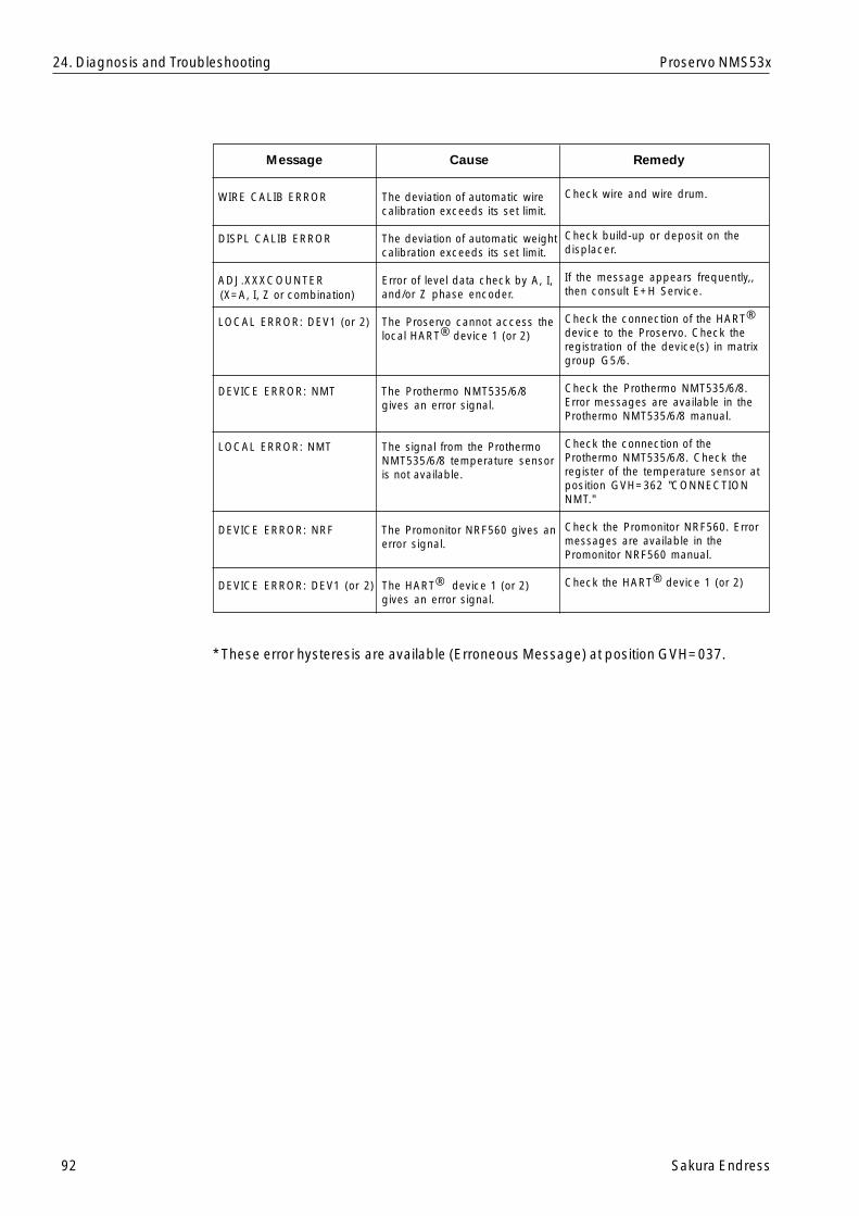
92 Sakura Endress
Proservo NMS53x
WIRE CALIB ERROR The deviation of automatic wirecalibration exceeds its set limit.
DISPL CALIB ERROR The deviation of automatic weightcalibration exceeds its set limit.
ADJ.XXXCOUNTER Error of level data check by A, I,and/or Z phase encoder.
LOCAL ERROR: DEV1 (or 2) The Proservo cannot access thelocal HART® device 1 (or 2)
DEVICE ERROR: NMT The Prothermo NMT535/6/8gives an error signal.
LOCAL ERROR: NMT The signal from the ProthermoNMT535/6/8 temperature sensoris not available.
DEVICE ERROR: NRF The Promonitor NRF560 gives anerror signal.
DEVICE ERROR: DEV1 (or 2) The HART® device 1 (or 2)gives an error signal.
Message Cause Remedy
Check wire and wire drum.
Check build-up or deposit on thedisplacer.
If the message appears frequently,,then consult E+H Service.
Check the connection of the HART®
device to the Proservo. Check theregistration of the device(s) in matrixgroup G5/6.
Check the Prothermo NMT535/6/8.Error messages are available in theProthermo NMT535/6/8 manual.
Check the connection of theProthermo NMT535/6/8. Check theregister of the temperature sensor atposition GVH=362 "CONNECTIONNMT."
Check the Promonitor NRF560. Errormessages are available in thePromonitor NRF560 manual.
Check the HART® device 1 (or 2)
(X=A, I, Z or combination)
* These error hysteresis are available (Erroneous Message) at position GVH=037.
24. Diagnosis and Troubleshooting
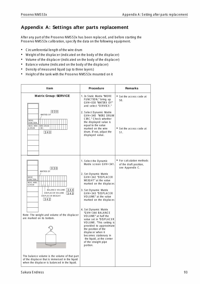
Sakura Endress 93
Proservo NMS53x
Appendix A: Settings after parts replacement
After any part of the Proservo NMS53x has been replaced, and before starting theProservo NMS53x calibration, specify the data on the following equipment.
• Circumferential length of the wire drum• Weight of the displacer (indicated on the body of the displacer)• Volume of the displacer (indicated on the body of the displacer)• Balance volume (indicated on the body of the displacer)• Density of measured liquid (up to three layers)• Height of the tank with the Proservo NMS53x mounted on it
Item RemarksProcedure
Matrix Group: SERVICE • Set the access code at50.
1. In Static Matrix "MOREFUNCTION," bring upGVH=030 "MATIRX OF"and select "SERVICE."
2. Select Dynamic MatrixGVH=340 "WIRE DRUMCIRC." Check whetherthe displayed value isequal to the valuemarked on the wiredrum. If not, adjust thedisplayed value.
1. Select the DynamicMatrix screen GVH=341.
2. Set Dynamic MatrixGVH=342 "DISPLACERWEIGHT" at the valuemarked on the displacer.
3. Set Dynamic MatrixGVH=343 "DISPLACERVOLUME" at the valuemarked on the displacer.
4. Set Dynamic Matrix"GVH=344 BALANCEVOLUME" at half thevalue set in "DISPLACERVOLUME. "This setting isprovided to approximatethe position of thedisplacer when itbecomes stationary in the liquid, at the centerof the straight pipeportion.
• Set the access code at51.
• For calculation methodsof the draft position,see Appendix C.
The balance volume is the volume of that partof the displacer that is immersed in the liquidwhen the displacer is balanced in the liquid.
Note: The weight and volume of the displacerare marked on its bottom.
Appendix A: Setting after parts replacement
WIRE DRUMCIRC.
MEAS. WIRE& DRUM
MATRIX OF
MOREFUNCTION
0 3 0
3 4 0
BALANCE VOLUME
DISPLACER VOLUMEDISPLACER WEIGHT
MEAS. WIRE& DRUM
MATRIX OF
MOREFUNCTION
0 3 0
3 4 43 4 3
3 4 2
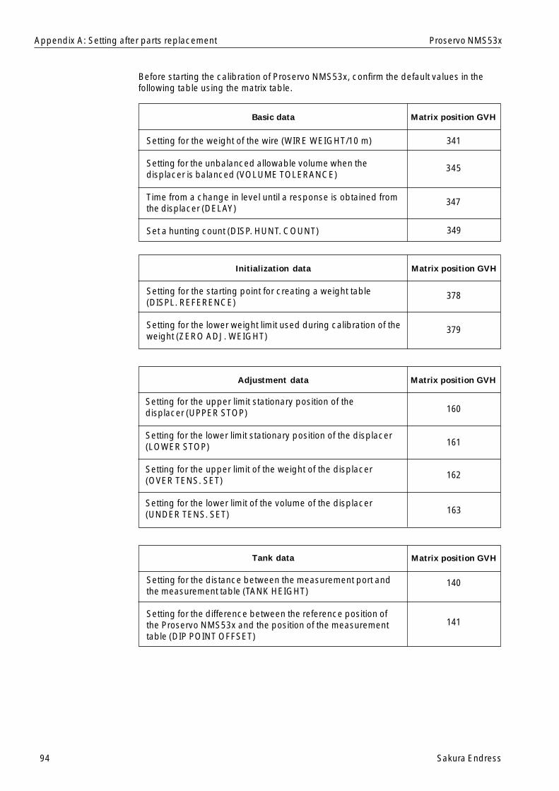
94 Sakura Endress
Proservo NMS53xAppendix A: Setting after parts replacement
Before starting the calibration of Proservo NMS53x, confirm the default values in thefollowing table using the matrix table.
Basic data Matrix position GVH
Setting for the weight of the wire (WIRE WEIGHT/10 m)
Setting for the unbalanced allowable volume when thedisplacer is balanced (VOLUME TOLERANCE)
Time from a change in level until a response is obtained fromthe displacer (DELAY)
Set a hunting count (DISP. HUNT. COUNT)
341
345
347
349
Initialization data Matrix position GVH
Setting for the starting point for creating a weight table(DISPL. REFERENCE)
Setting for the lower weight limit used during calibration of theweight (ZERO ADJ. WEIGHT)
378
379
Adjustment data Matrix position GVH
163
Setting for the upper limit stationary position of thedisplacer (UPPER STOP)
Setting for the lower limit stationary position of the displacer(LOWER STOP)
Setting for the upper limit of the weight of the displacer(OVER TENS. SET)
Setting for the lower limit of the volume of the displacer(UNDER TENS. SET)
Tank data Matrix position GVH
140
141
Setting for the distance between the measurement port andthe measurement table (TANK HEIGHT)
Setting for the difference between the reference position ofthe Proservo NMS53x and the position of the measurementtable (DIP POINT OFFSET)
160
161
162
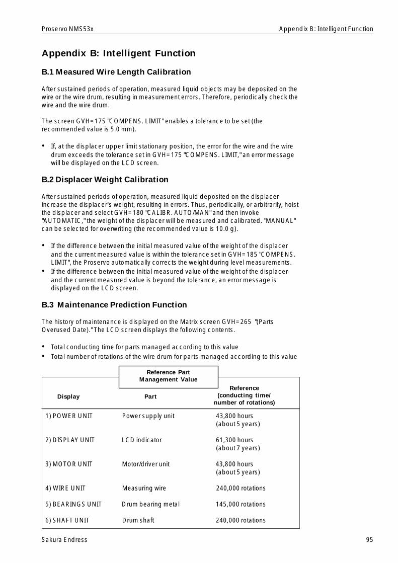
Sakura Endress 95
Proservo NMS53x
Appendix B: Intelligent Function
B.1 Measured Wire Length Calibration
After sustained periods of operation, measured liquid objects may be deposited on thewire or the wire drum, resulting in measurement errors. Therefore, periodically check thewire and the wire drum.
The screen GVH=175 "COMPENS. LIMIT" enables a tolerance to be set (therecommended value is 5.0 mm).
• If, at the displacer upper limit stationary position, the error for the wire and the wiredrum exceeds the tolerance set in GVH=175 "COMPENS. LIMIT," an error messagewill be displayed on the LCD screen.
B.2 Displacer Weight Calibration
After sustained periods of operation, measured liquid deposited on the displacerincrease the displacer's weight, resulting in errors. Thus, periodically, or arbitrarily, hoistthe displacer and select GVH=180 "CALIBR. AUTO/MAN" and then invoke"AUTOMATIC," the weight of the displacer will be measured and calibrated. "MANUAL"can be selected for overwriting (the recommended value is 10.0 g).
• If the difference between the initial measured value of the weight of the displacerand the current measured value is within the tolerance set in GVH=185 "COMPENS.LIMIT", the Proservo automatically corrects the weight during level measurements.
• If the difference between the initial measured value of the weight of the displacerand the current measured value is beyond the tolerance, an error message isdisplayed on the LCD screen.
B.3 Maintenance Prediction Function
The history of maintenance is displayed on the Matrix screen GVH=265 "(PartsOverused Date)." The LCD screen displays the following contents.
• Total conducting time for parts managed according to this value• Total number of rotations of the wire drum for parts managed according to this value
1) POWER UNIT Power supply unit 43,800 hours(about 5 years)
2) DISPLAY UNIT LCD indicator 61,300 hours(about 7 years)
3) MOTOR UNIT Motor/driver unit 43,800 hours(about 5 years)
4) WIRE UNIT Measuring wire 240,000 rotations
5) BEARINGS UNIT Drum bearing metal 145,000 rotations
6) SHAFT UNIT Drum shaft 240,000 rotations
Display PartReference
(conducting time/number of rotations)
Reference PartManagement Value
Appendix B: Intelligent Function
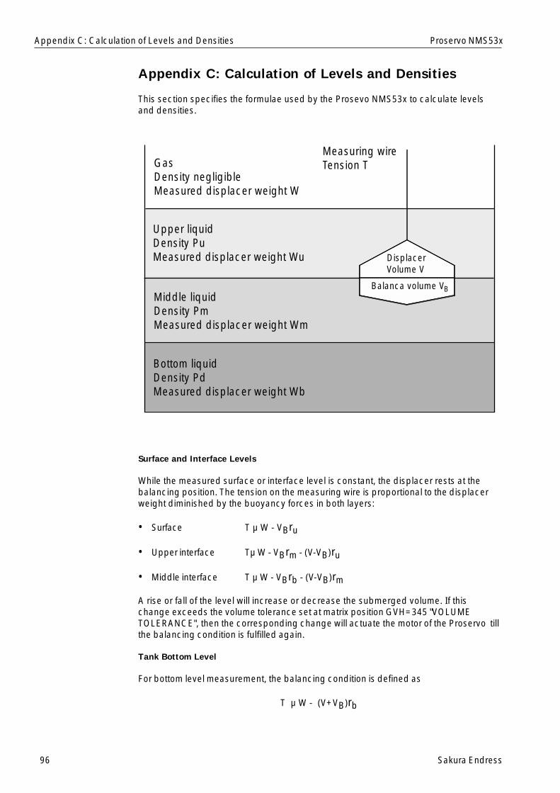
96 Sakura Endress
Proservo NMS53x
Appendix C: Calculation of Levels and Densities
This section specifies the formulae used by the Prosevo NMS53x to calculate levelsand densities.
Appendix C: Calculation of Levels and Densities
Surface and Interface Levels
While the measured surface or interface level is constant, the displacer rests at thebalancing position. The tension on the measuring wire is proportional to the displacerweight diminished by the buoyancy forces in both layers:
• Surface T µ W - VBru
• Upper interface Tµ W - VBrm - (V-VB)ru
• Middle interface T µ W - VBrb - (V-VB)rm
A rise or fall of the level will increase or decrease the submerged volume. If thischange exceeds the volume tolerance set at matrix position GVH=345 "VOLUMETOLERANCE", then the corresponding change will actuate the motor of the Proservo tillthe balancing condition is fulfilled again.
Tank Bottom Level
For bottom level measurement, the balancing condition is defined as
T µ W - (V+VB)rb
DisplacerVolume V
Balanca volume VB
Measuring wireTension TGas
Density negligibleMeasured displacer weight W
Upper liquidDensity PuMeasured displacer weight Wu
Middle liquidDensity PmMeasured displacer weight Wm
Bottom liquidDensity PdMeasured displacer weight Wb

Sakura Endress 97
Proservo NMS53x
Densities
The upper, middle, and bottom densities are calculated by the following formulae:
• Upper density
• Middle density
• Bottom density
Draught
The draught depends on the shape of the displacer. For conical shape, the draught is
where the variables and constants have the following meanings;
V2 Submerged volumeV1 Volume of the lower coneh Height of the lower coned Diameter of the displacer
The surface or interface level should be within the cylindrical part of the displacer andapproximately in the middle of its total height.
The table shows the draught of a conical displacer with V1 = 4.23 ml, h = 7 mm, andd = 50 mm for some values of the submerged volume.
Vs [ml] D [mm]
25 17.6
50 30.3
60 35.4
65 38.0
Appendix C: Calculation of Levels and Densities
Pu =W - Wu
V
Pm =Wu - Wm
+ Pu
V
Pb =Wm - Wb
+ Pm
V
D =4000( )V - Vs 1
h +� d
2
Surfaceor interface
D
d
h
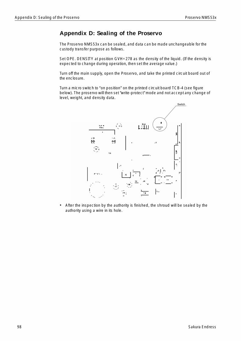
98 Sakura Endress
Proservo NMS53x
Appendix D: Sealing of the Proservo
The Proservo NMS53x can be sealed, and data can be made unchangeable for thecustody transfer purpose as follows.
Set OPE. DENSITY at position GVH=278 as the density of the liquid. (If the density isexpected to change during operation, then set the average value.)
Turn off the main supply, open the Proservo, and take the printed circuit board out ofthe enclosure.
Turn a micro switch to “on position” on the printed circuit board TCB-4 (see figurebelow). The proservo will then set "write-protect" mode and not accept any change oflevel, weight, and density data.
• After the inspection by the authority is finished, the shroud will be sealed by theauthority using a wire in its hole.
Appendix D: Sealing of the Proservo
Switch
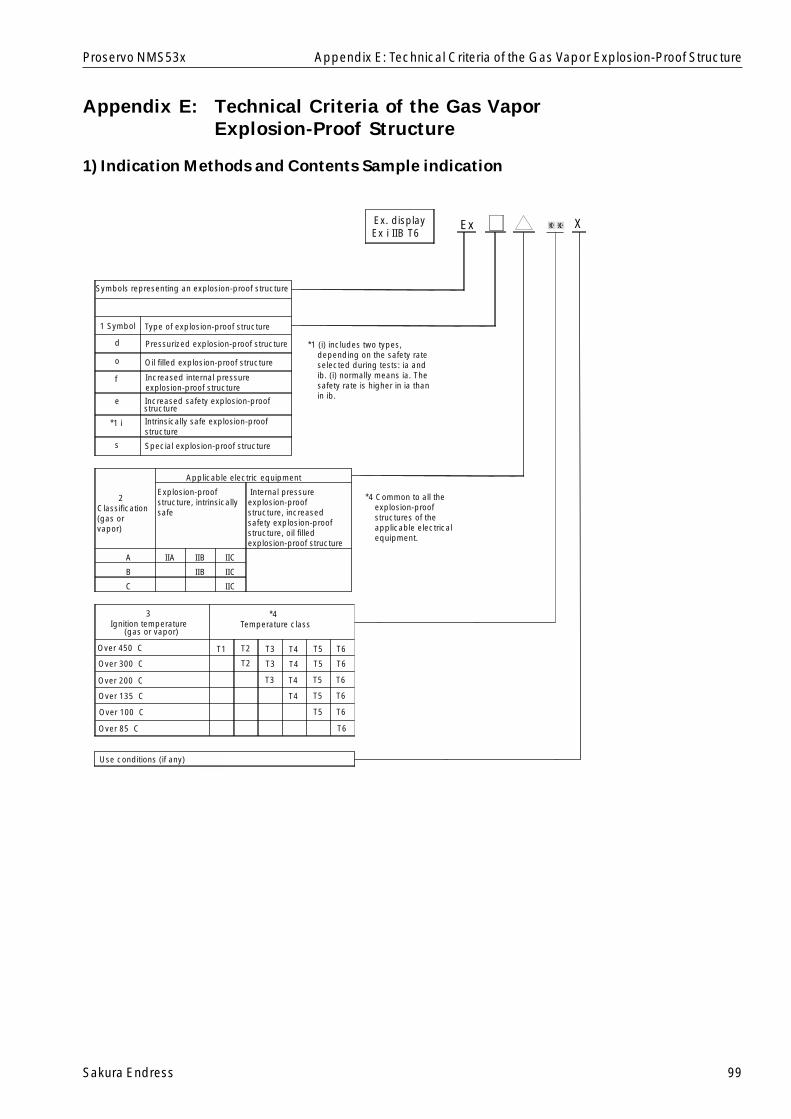
Sakura Endress 99
Proservo NMS53x
Appendix E: Technical Criteria of the Gas VaporExplosion-Proof Structure
1) Indication Methods and Contents Sample indication
Appendix E: Technical Criteria of the Gas Vapor Explosion-Proof Structure
Ex X....X ....X
Symbols representing an explosion-proof structure
1 Symbol Type of explosion-proof structure
d Pressurized explosion-proof structure
o Oil filled explosion-proof structure
f eIncreased internal pressurexplosion-proof structure
estructurIncreased safety explosion-proof
e
*1 i Intrinsically safe explosion-proofstructure
s Special explosion-proof structure
2Classification(gas orvapor)
Applicable electric equipment
Explosion-proofstructure, intrinsicallysafe
Internal pressureexplosion-proofstructure, increasedsafety explosion-proofstructure, oil filledexplosion-proof structure
A IIA IIB IIC
B IIB IIC
C IIC
3Ignition temperature
(gas or vapor)
*4Temperature class
Over 450 C T1 T2
T2
T3
T3
T3
T4
T4
T4
T4
T5
T5
T5
T5
T5
T6
T6
T6
T6
T6
T6
Over 300 C
Over 200 C
Over 135 C
Over 100 C
Over 85 C
Use conditions (if any)
Ex. displayEx i IIB T6
*1 (i) includes two types,depending on the safety rateselected during tests: ia andib. (i) normally means ia. Thesafety rate is higher in ia thanin ib.
*4 Common to all theexplosion-proofstructures of theapplicable electricalequipment.
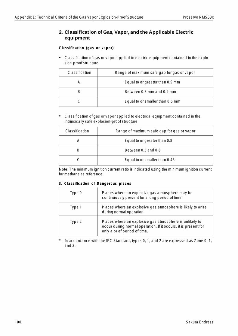
100 Sakura Endress
Proservo NMS53x
2. Classification of Gas, Vapor, and the Applicable Electricequipment
Classification (gas or vapor)Classification (gas or vapor)Classification (gas or vapor)Classification (gas or vapor)Classification (gas or vapor)
• Classification of gas or vapor applied to electric equipment contained in the explo-sion-proof structure
Classification Range of maximum safe gap for gas or vapor
A Equal to or greater than 0.9 mm
B Between 0.5 mm and 0.9 mm
C Equal to or smaller than 0.5 mm
• Classification of gas or vapor applied to electrical equipment contained in theintrinsically safe explosion-proof structure
Classification Range of maximum safe gap for gas or vapor
A Equal to or greater than 0.8
B Between 0.5 and 0.8
C Equal to or smaller than 0.45
Note: The minimum ignition current ratio is indicated using the minimum ignition currentfor methane as reference.
3. Classification of Dangerous places3. Classification of Dangerous places3. Classification of Dangerous places3. Classification of Dangerous places3. Classification of Dangerous places
Type 0 Places where an explosive gas atmosphere may becontinuously present for a long period of time.
Type 1 Places where an explosive gas atmosphere is likely to ariseduring normal operation.
Type 2 Places where an explosive gas atmosphere is unlikely tooccur during normal operation. If it occurs, it is present foronly a brief period of time.
* In accordance with the IEC Standard, types 0, 1, and 2 are expressed as Zone 0, 1,and 2.
Appendix E: Technical Criteria of the Gas Vapor Explosion-Proof Structure
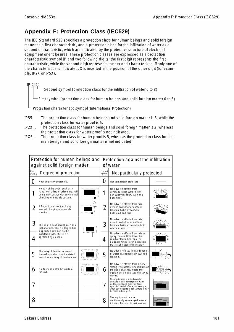
Sakura Endress 101
Proservo NMS53x
Appendix F: Protection Class (IEC529)The IEC Standard 529 specifies a protection class for human beings and solid foreignmatter as a first characteristic, and a protection class for the infiltration of water as asecond characteristic, which are indicated by the protective structure of electricalequipment or enclosures. These protection classes are expressed as a protectioncharacteristic symbol IP and two following digits; the first digit represents the firstcharacteristic, while the second digit represents the second characteristic. If only one ofthe characteristics is indicated, X is inserted in the position of the other digit (for exam-ple, IP2X or IP5X).
IPSecond symbol (protection class for the infiltration of water 0 to 8)
First symbol (protection class for human beings and solid foreign matter 0 to 6)
Protection characteristic symbol (International Protection)
IP55... The protection class for human beings and solid foreign matter is 5, while theprotection class for water proof is 5.
IP2X... The protection class for human beings and solid foreign matter is 2, whereasthe protection class for water proof is not indicated.
IPX5... The protection class for water proof is 5, whereas the protection class for hu-man beings and solid foreign matter is not indicated.
Appendix F: Protection Class (IEC529)
Protection for human beings and against solid foreign matter
First symbol Degree of protection
Not completely protected.
No part of the body, such as a hand, with a large surface area will come into contact with any internal charging or movable section.
A fingertip can not touch any internal charging or movable \section.
The tip of a solid object such as a tool or a wire, which is larger than a specified size can not beinserted inside. The size is specified by classes.
The entry of dust is prevented. Normal operation is not inhibited even if some entry of dust occurs.
No dust can enter the inside of the unit.
Secondsymbol Not particularly protected
Protection against the infiltration of water
Not completely protected.
No adverse effects from vertically falling water drops; non-windy location, such as a basement.
No adverse effects from rain, even in an indoor or outdoor location that is exposed to both wind and rain
No adverse effects from rain, even in an indoor or outdoor location that is exposed to both wind and rain.
No adverse effects from rain or spray, on a tall iron tower that is subjected to horizontal or diagonal winds , or in a location that is subjected only to spray.
No advers effects from a direct jet of water in a periodically washed location.
No adverse effects from a direct, strong jet of water, for example, onthe deck of a ship, where the equipment is subjected directly to waves.The equipment is not adversely affected if it is submerged in water under a specified pressure for a specified period of time, for example, when used beside a pool, where it may become submerged.
The equipment can be continuously submerged in water if it must be used in that manner.
0
1
2
3
4
5
6
7
8
0
1
2
3
4
5
6
7
8
15
60 60
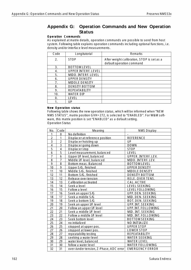
102 Sakura Endress
Proservo NMS53x
Appendix G: Operation Commands and New OperationStatus
Operation CommandsOperation CommandsOperation CommandsOperation CommandsOperation CommandsAs explained at matrix details, operation commands are possible to send from hostsystem. Following table explains operation commands including optional functions, i.e.density and/or interface level measurements.
2. STOP After weight calibration, STOP is set as adefault operation command
3. BOTTOM LEVEL4. UPPER INTERF. LEVEL5. MIDD. INTERF. LEVEL6. UPPER DENSITY7. MIDDLE DENSITY8. DENSITY BOTTOM9. REPEATABILITY10. WATER DIP0. LEVEL1. UP
New Operation statusNew Operation statusNew Operation statusNew Operation statusNew Operation statusFollowing table shows the new operation status, which will be informed when “NEWNMS STATUS”, matrix position GVH=272, is selected to “ENABLED”. For W&M soft-ware, this matrix position is set “ENABLED” as a default setting.Operation Status
No. Code Meaning NMS Display1 0 No definition -2 1 Displacer at reference position REFERENCE3 2 Displacer hoisting up UP4 3 Displacer going down DOWN5 4 Displacer stop STOP6 5 Level measurement, balanced LEVEL7 6 Upper I/F level, balanced UPPER. INTERF. LEV.8 7 Middle I/F level, balanced MIDD. INTERF. LEV.9 8 Bottom meas. Balanced BOTTOM LEVEL10 9 Upper S/G, finished UPPER DENSITY11 10 Middle S/G, finished MIDDLE DENSITY12 11 Bottom S/G, finished DENSITY BOTTOM13 12 Release over tension RELE. OVER TENS.14 13 Calibration activated CAL. ACTIVE15 14 Seek a level LEVEL SEEKING16 15 Follow a level LEVEL FOLLOWING17 16 Seek an upper S/G UPP. DEN. SEEKING18 17 Seek a middle S/G MID. DEN. SEEKING19 18 Seek a bottom S/G BOT. DEN. SEEKING20 19 Seek an upper I/F level UPP. INT. SEEKING21 20 Follow an upper I/F level UPP. INT. FOLLOWING22 21 Seek a middle I/F level MID. INT. SEEKING23 22 Follow a middle I/F level MID. INT. FOLLOWING24 23 Seek bottom level BOTTOM SEEKING25 24 no initialized NO INITIALIZE26 25 stopped at upper pos. UPPER STOP27 26 stopped at lower pos. LOWER STOP28 27 repeatability testing REPEATABILITY29 28 seeking a water level WATER SEEKING30 29 water level, balanced WATER LEVEL31 30 follow a water level WATER FOLLOWING32 31 over-/under tension, Z-Phase, ADC error EMERGENCY ERROR
Appendix G: Operation Commands and New Operation Status
Longitutorial RemarksCode
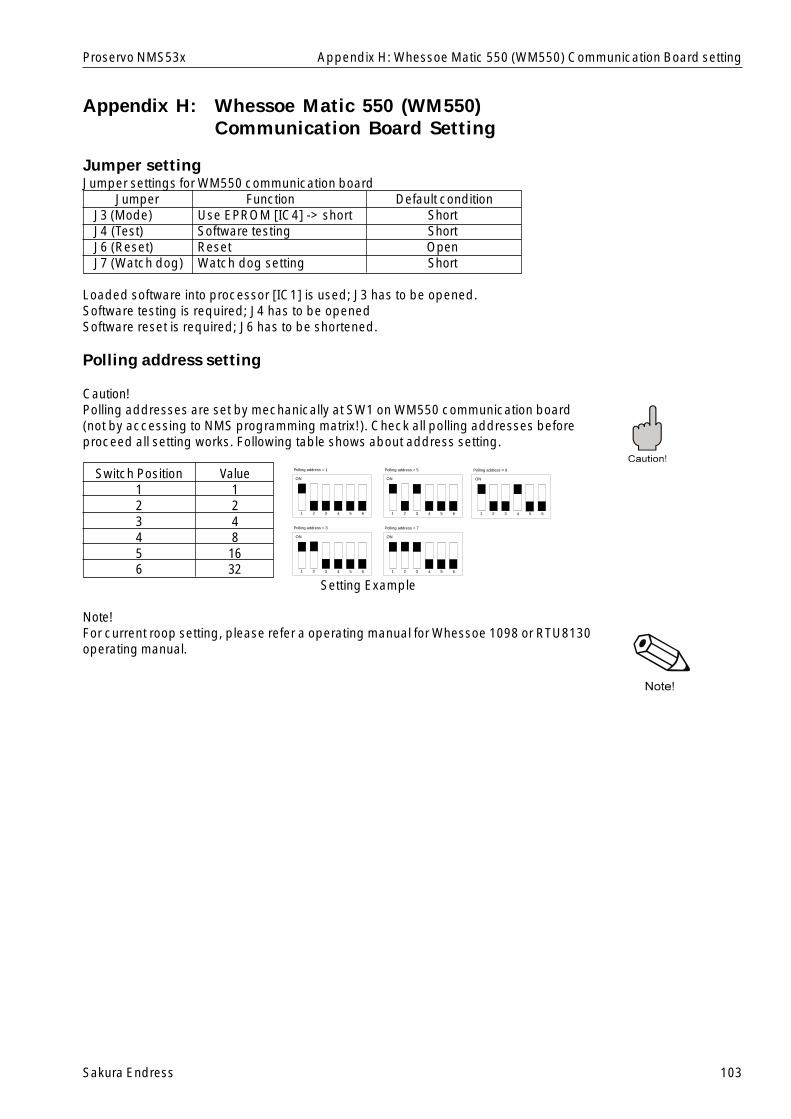
Sakura Endress 103
Proservo NMS53x
Appendix H: Whessoe Matic 550 (WM550)Communication Board Setting
Jumper settingJumper settings for WM550 communication board
Jumper Function Default conditionJ3 (Mode) Use EPROM [IC4] -> short ShortJ4 (Test) Software testing ShortJ6 (Reset) Reset OpenJ7 (Watch dog) Watch dog setting Short
Loaded software into processor [IC1] is used; J3 has to be opened.Software testing is required; J4 has to be openedSoftware reset is required; J6 has to be shortened.
Polling address setting
Caution!Polling addresses are set by mechanically at SW1 on WM550 communication board(not by accessing to NMS programming matrix!). Check all polling addresses beforeproceed all setting works. Following table shows about address setting.
Switch Position Value1 12 23 44 85 166 32
Setting Example
Note!For current roop setting, please refer a operating manual for Whessoe 1098 or RTU8130operating manual.
Appendix H: Whessoe Matic 550 (WM550) Communication Board setting
ON
1 2 3 4 5 6
Polling address = 1
ON
1 2 3 4 5 6
Polling address = 5
ON
1 2 3 4 5 6
Polling address = 9
ON
1 2 3 4 5 6
Polling address = 3
ON
1 2 3 4 5 6
Polling address = 7
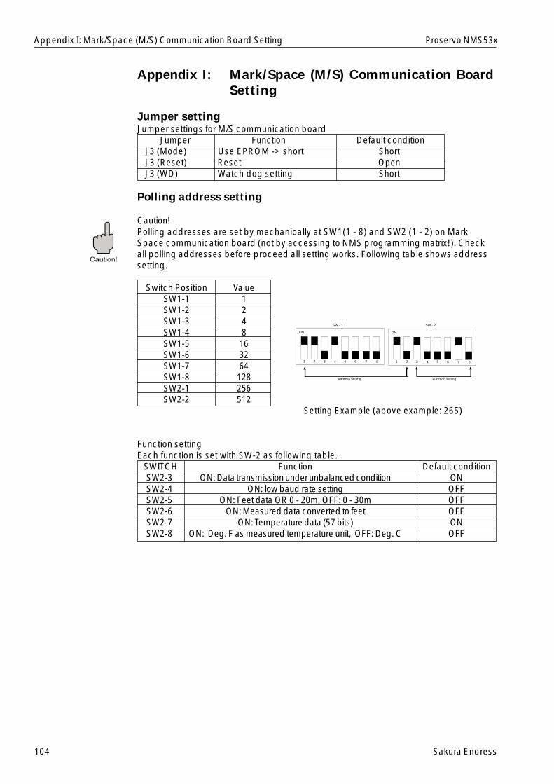
104 Sakura Endress
Proservo NMS53x
Appendix I: Mark/Space (M/S) Communication BoardSetting
Jumper settingJumper settings for M/S communication board
Jumper Function Default conditionJ3 (Mode) Use EPROM -> short ShortJ3 (Reset) Reset OpenJ3 (WD) Watch dog setting Short
Polling address setting
Caution!Polling addresses are set by mechanically at SW1(1 - 8) and SW2 (1 - 2) on MarkSpace communication board (not by accessing to NMS programming matrix!). Checkall polling addresses before proceed all setting works. Following table shows addresssetting.
Switch Position ValueSW1-1 1SW1-2 2SW1-3 4SW1-4 8SW1-5 16SW1-6 32SW1-7 64SW1-8 128SW2-1 256SW2-2 512
Setting Example (above example: 265)
Function settingEach function is set with SW-2 as following table.
SWITCH Function Default conditionSW2-3 ON: Data transmission under unbalanced condition ONSW2-4 ON: low baud rate setting OFFSW2-5 ON: Feet data OR 0 - 20m, OFF: 0 - 30m OFFSW2-6 ON: Measured data converted to feet OFFSW2-7 ON: Temperature data (57 bits) ONSW2-8 ON: Deg. F as measured temperature unit, OFF: Deg. C OFF
Appendix I: Mark/Space (M/S) Communication Board Setting
ON
1 2 3 4 5 6 7 8
ON
1 2 3 4 5 6 7 8
SW - 1 SW - 2
Address setting Function setting
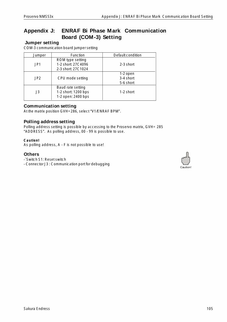
Sakura Endress 105
Proservo NMS53x
Jumper settingCOM-3 communication board jumper setting
Jumper Function Default conditionROM type setting
JP1 1-2 short: 27C4096 2-3 short2-3 short: 27C1024
1-2 openJP2 CPU mode setting 3-4 short
5-6 shortBaud rate setting
J3 1-2 short: 1200 bps 1-2 short1-2 open: 2400 bps
Communication settingAt the matrix position GVH=286, select “V1/ENRAF BPM”.
Polling address settingPolling address setting is possible by accessing to the Proservo matrix, GVH= 285“ADDRESS”. As polling address, 00 - 99 is possible to use.
Caut ion!Caut ion!Caut ion!Caut ion!Caut ion!As polling address, A - F is not possible to use!
Others-´Switch S1: Reset switch- Connector J3 : Communication port for debugging
Appendix J: ENRAF Bi Phase Mark CommunicationBoard (COM-3) Setting
Appendix J: ENRAF Bi Phase Mark Communication Board Setting
106 Sakura Endress
Proservo NMS53x
Glossary
AAAAAA/D converter A circuit for converting an analogue signal into a digital
signal.Access Code An identification number required to switch the matrix
or to change set dataAD Count A number that is a count value represents the digital
signal into which the analogue output of the Hall sensoris converted.
Alarm Contact A contact output if it reaches a certain value or meets acertain condition.
Alarm Relay A relay that outputs a contact if it reaches a certainvalue or meets a certain condition.
Analogue Signal A signal with a temporally continuous valueAnchor Weight A weight used in the guide wire method when the wire
hook cannot be welded to the bottom of the tank.Asymmetric Pipe A short pipe that is used for the steel pipe method and
that is mounted between the pipe in the tank and theProservo NMS53x flange to connect them byeccentrically varying its diameter if there is a differencebetween the pipe and the Proservo NMS53x flange indiameter.
Automatic Compensation After a long operation time, deposits are collected onthe Weight Data displacer, resulting in a change in theweight of the displacer. This function automaticallycorrects such change.
BBBBBBalance The displacer is balanced and can detect the level or
the interface.Balance Volume The volume (ml) of that part of the displacer, which is
submerged in the liquid when it is balanced.Bearing Unit A section that holds the shaft of the wire drum.Burr Protrusions that occur when steel pipes are welded,
connected, or cut.
CCCCCCable A collection of various conductors, which are provided
with a cover.Cable Gland A fixture installed to draw the cable into the terminal
box.Calibration Adjustment or calibration conducted after suspending
the operation.Calibration Window A window for checking the position of the displacer
after calibration.Calibration Window Reference A position or line used as a reference duringLine calibration.Chamber for Maintenance A T-shaped, short pipe normally mounted for
maintenance when the guide wire method and apressurized tank are used.
Circumference of the Wire The length of the wire rolled around the wire drum perDrum its rotation.
Glossary
Sakura Endress 107
Proservo NMS53x
Common A wire common to plural signals of the same type(potential)
Communication I C (SIFA) A sensor interface ASIC (a customer IC) developed byEndress+Houser Inc. and having various functions. InProservo NMS53x, it is used as an integrated circuit toprocess HART signals.
Concentric Pipe A short pipe that is used for the steel pipe method andthat is mounted between the pipe in the tank and theProservo NMS53x flange to connect them byconcentrically varying its diameter if there is adifference between the pipe and the Proservo NMS53xflange in diameter.
Conductivity S/m or an inverse of the resistance rate (j/m).According to the Ohm’s law, I = eE is establishedwherein (I) is the density of a current, “E” is anelectrolytic strength, and e is a conducting rate.
Conical Displacer A displacer shape.Contact Output A close signal that can be obtained when the relay is
activated.Correction of Balance A condition in which the apparatus is operating very
slowly to find a balance point.Correction value for tank roof Distortion rate mm/mdistortionCovered Floating Roof Tank A tank with a double roof.
IIIIIInsulation Voltage Cables, the covers of which are not damaged if a
disturbance of a relatively high voltage level occurs.Intelligent Thermometer A thermometer with a microcomputer (Prothermo
NMT535/6/7 series thermometers)Interface Measurement Measuring the depth of the interface between multiple
liquids if they are completely separated from eachother.
Interface measurement To measure the depth of the interface between multipleliquids that are completely separated from one another.
IP67 (water proof) One of the protection class symbols specified in theJIS Standard.
JJJJJJumper Pin A pin used to connect multiple portions in order to
create a certain condition.
KKKKKKink A condition in which the measuring wire is bent.
LLLLLLCD Liquid crystal displayLevel The level at which, during level measurements, the
displacer is first balanced after being lowered from thereference position.
Level Measurement A condition in which Proservo NMS53x detects thelevel.
Line Resistance A value input to adjust the resistance of a transmissionpath used for communication with the exclusivereceiver.
Glossary

108 Sakura Endress
Proservo NMS53x
Low Weight A set value required during adjustments in order toaccurately measure the weight (0.0 g).
Lower Stop The position at which the motor automatically stopswhen, during measurements, the value of the level,interface, or tank bottom falls below the set value.
MMMMMManaged part A part that is periodically changed.Matrix Position LCD display screens for the static and the dynamic
matrixes.Maximum Correction Value The maximum value of the corrections (the weight
of the displacer minus the measured weight) storedafter the creation of a weight table.
Measurement Port A port through which the operator inserts ameasurement tape to measure the height of theliquid in the tank from its bottom.
Measurement Port Reference A roof-side reference position for measurements.PositionMeasuring Wire A wire used to hoist the displacer.Measuring Wire Tension Applied tension when the measuring wire is pulled
in the direction of the displacer.Middle Density The density of the intermediate layer of liquid when
three types of liquids are separated from oneanother.
Middle Interface Level The boundary between the intermediate layer ofliquid and the lower layer of liquid when three typesof liquids are separated from one another.
Minimum Weight Correction The minimum value of the corrections (the weight ofValue the displacer minus the measured weight) stored
after the creation of a weight table.Mounting Nozzle A short pipe disposed at the top of the tank to
mount Proservo NMS53x on it.
NNNNNNormal Close A contact is closed during normal operation and
opened when a set value is reached.Normal Open A contact is open during normal operation and
closed when a set value is reached.Number of Cable Cores The number of conductor cores accommodated in
the covered cable.OOOOOOperation Parameter Set values and data required for operations.Optical Operating Element A part (a product) that provides an optical signal
when touched by a hand.Output Outputting information or data in Proservo NMS53x.Over Tension An error in which the weight detected by the
detector exceeds the upper limit (set value).Over Tension A set value used to automatically stop level
measurements if a weight larger than a specifiedvalue is applied to the measuring wire, in order toprevent the wire from snapping.
PPPPPPE Polyethylene (a synthetic resin)Power Supply Cable An electric wire that supplies power to the power
supply section.Power Unit An electric circuit for generating power required to
operate the apparatus.
Glossary
Sakura Endress 109
Proservo NMS53x
Programming Matrix A collective name for the static and the dynamicmatrixes.
Pt100 ohm RTD Input Platinum resistance 100 ohm input (spot thermometerinput)
PTEE Poly Tetra Fluore Ethylene; commonly referred to as“Teflon”.
PVC Stands for Poly Vinyl Chloride (a synthetic resin).
RRRRRRACK BUS A digital signal used in a rack system commercially
available from Endress+Hauser.RACK BUS RS485 A digital communication method in which a rack bus is
used for field communications.Receiver Protocol A unique address assigned to Proservo NMS53x in
order to communicate with a receiver.Relay Output A contact signal output when the contact reaches a
certain value or meets a certain condition.Resistance The longer a cable is or the smaller its cross section is,
the more difficulty a current has in flowing through thecable. The resistance value represents the degree ofsuch a difficulty.
Resistor input An input to a spot thermometer.Rod A stick-like object used to adjust the weight of the
displacer by somewhat raising the displacer.
SSSSSSerial bus (pulse) A signal that enables a large amount of information to
be exchanged between multiple devices through twocables.
Serial Pulse Output A form of signal communication in which data can beupdated in both directions, that is, during bothtransmission and reception. Proservo NMS53x uses anexclusive pulse signal for this form of communication.
Spherical tank A spherical tank that is often used as a high pressuretank.
Stilling Well A steel pipe generally made of iron that is often usedfor a floating roof tank.
Support A supporting plate for fixing the wire drum to the drumchamber.
SUS316 One of the metallic materials and their grades specifiedin the JIS Standard (SUS means stainless).
Static Matrix A group of matrixes that display and set basic data forProservo NMS53x.
TTTTTTank Bottom The bottom surface of the tank (bottom plate, zero
point)Tank Roof Distortion The degree of the expansion of the side and the
bottom walls of the tank varies depending on whetherthe tank is empty or filled.
Tank Side Monitor Displays at the starting portion of a companionway thesame data on the level and temperature as in theProservo NMS53x disposed on the tank (PromonitorNRF560).
Tape-armored Measuring One type of measuring cable that is used to provideCable mechanical protection against external force.Terminal Block A relay point used when equipment is connected to the
cables and operated.
Glossary
110 Sakura Endress
Proservo NMS53x
Terminating Resistance An impedance that is used to terminate the transmissionpath and that is approximately equal to the characteristicimpedance of the line.
Tolerance A tolerance used in measurements. In the ProservoNMS53x matrix, it is considered to be a maximum valuethat can be output in the presence of an error.
Touch Control The operator can touch the touch control to change thedisplay and to carry out calibrations and operations.
Twisted Pair One or more pairs of twisted cables wrapped by ametallic tape or net, which is further covered with aninsulating material.
UUUUUUllage Level The distance between the measurement port and the
interface.Unbalanced Status A condition in which the displacer can not detect the level
accurately.Under Tension A set value used to indicated when the weight detected
by the detector is abnormally small compared to theweight of the displacer.
Upper Density Density of the top layer of liquid, when three types ofliquids are separated from one another.
Upper Interface Level The boundary between the highest layer of liquid and thesecond highest layer of liquid, when three types of liquidsare separated from one another.
Upper Plate A metallic plate mounted immediately below the Proservoflange in the guide-wire method in order to fix the guidewires.
VVVVVValve A valve for a pressurized tank, which releases the
pressure from the tank during maintenance.Very Accurate Measurement A mode used to guarantee higher accuracy in levelMode measurements.Voltage Drop A phenomenon in which a current flowing through a
resistor or an inductor causes the voltage to decrease.Volume tolerance Changes in weight, from balanced status to the beginning
of the movement of the displacer, are based on thisvolume.
WWWWWWeight Calibration Adjustments provided to accurately measure the weightWeight Correction Curve A curve generated when the correction values (the weight
of the displacer minus the measured weight) stored afterthe creation of a weight table are expressed in a graph.
Weight Table Correction values used to automatically save the(drum correction values) imbalance on the diagonal line on the wire drum.Wire drum A part that the measuring wire is rolled around to convert
the distance over which the displacer has moved into arotational movement in order to transmit it to the detector.
Wire Hook A fixture that is used for the guide wire method andaround which the terminal of the guide wire is wound.
Without Guide System A Proservo NMS53x mounting method that does not usethe guide wires or the steel pipes.
ZZZZZZ Phase Signal One pulse output from the level encoder every 300mm.
Glossary
Sakura Endress 111
Proservo NMS53x Index
Index
AAccess code................................................. 30, 31Alarm ...................................................... 18, 80~81Analogue output ............................... 18, 51, 85~86Asymmetric pipe .......................................... 12~13
BBalance............................................................... 74Balance volume .................................................. 52
CCable connection .......................................... 17~23Cable for input and/or output ........................ 17~23Cable glands ...................................................... 23Calculation of levels and densities ................ 96~97Calendar ....................................................... 46, 65Calibration............................................... 68~72, 76Clock ............................................................ 46, 65Custody transfer (Tax & weight) ...................... 8, 31
DDensity .................................................... 65, 77, 97Diagnosis ............................................................ 90Diagnostic code ............................................ 43, 90Diagnostic history ......................................... 43, 84Dimensions ........................................................... 9Dip point offset ............................................... 6, 44Displacer status ................................ 28~29, 62~64Displacer volume .......................................... 68~71Displacer weight ........................................... 68~73Display ............................................................... 26Draught ............................................................... 97Dynamic matrices ............................. 26~27, 44~61
EElectrostatic charge ........................................ 4, 16ENRAF BPM ......................................... 18~19, 105Error and status messages ........................... 90~91Explosion-proof type ........................... 3, 8, 99~100
FFlange ................................................................. 15Floating roof tank ................................................ 11
GGauge status ...................................................... 23Grounding ....................................................... 3, 18Guide wire..................................................... 11, 14
HHOME position .................................................... 28
IInitial Setting ................................................. 65~67Input ................................................................... 24Interface measurement ................................... 6, 79
JJumper .............................................. 103, 104, 105
LLanguage ............................................................ 46LCD .............................................................. 26, 46
MMaintenance prediction ....................................... 95Mark/Space (M/S) ................................. 22~23, 104Matrix groups ............................................... 26, 31Measuring wire ................................................ 4, 25Mounting ....................................................... 11~16Mounting preparations .................................. 15~16Mounting with guide wire .............................. 11, 14Mounting with stilling well ............................. 11~12Mounting without guide system .......................... 11
NNMT ............................................................ 5, 7, 88NRF ............................................................ 5, 7, 89
OOn-site calibration ......................................... 75~76Operating Contact ...................................18, 47, 87Operating elements ............................................ 26Operating of the displacer .................................. 73Output ....................................................... 5,18~24
PPipe .................................................... 4, 11~13, 15Pipe diameter ............................................... 12~13Power consumption ...................................... 17~24Power supply ............................................ 3, 17~24Power supply cable .................................. 3, 17~24Programming matrix .......................... 26~27, 31~61Protection class ............................................ 8, 101
RRackbus RS 485 ................................................. 81Remote communication ................................ 80~81Resister switch ................................................... 81
SSafety instructions ............................................ 3~4Sealing ................................................................ 98Serial pulse ......................................................... 80Specifications ....................................................... 8Static matrix .................................................. 31~32System configuration ........................................ 5~7
TTank height ..................................................... 6, 67Tools ................................................................... 10Touch control ................................................... 8, 26

112 Sakura Endress
Proservo NMS53x
VV1/022 protocol ................................................... 80
WWeight calibration ................................... 68~71, 95Weight table ....................................................... 72Whessoe Matic 550 (WM550) ............... 20~21, 103Wire length calibration ........................................ 95
ZZ phase check .............................................. 68~71
Index

Sakura Endress Co.,Ltd.862-1 Mitsukunugi,Sakaigawamura,Higashi-Yatsushirogun,Yamanashiken 406-0846Japan
Phone: ++81-55-266-4964Fax: ++81-55-266-4969E-mail: [email protected]
BA 001N/08/en/02.02Printed in Japan
Endress+HauserSystems & Gauging


