AA Holdings Pty Ltd Level 1, 40 Johnston Street Collingwood VIC 3066 C/- Beveridge Williams 1 Glenferrie Road Malvern VIC 3144 Attention: Chris White Dear Chris, RE: 92 Lot Residential Subdivision, 185 Rix Road Officer Geotechnical Investigation & Pavement Design Please find attached our report on the Geotechnical Investigation & Pavement Design for the 92 Lot Residential Subdivision project located at 185 Rix Road, Officer. Should you have any queries or comments regarding this report please feel free to contact the undersigned. Regards ………………………………………………………. Frank Tostovrsnik B.E. (Civil) Hons. Senior Geotechnical Engineer SITE GEOTECHNICAL PTY LTD
SITE GeotechnicalSoil Investigation Testing & Evaluation
SITE GeotechnicalSoil Investigation Testing & Evaluation
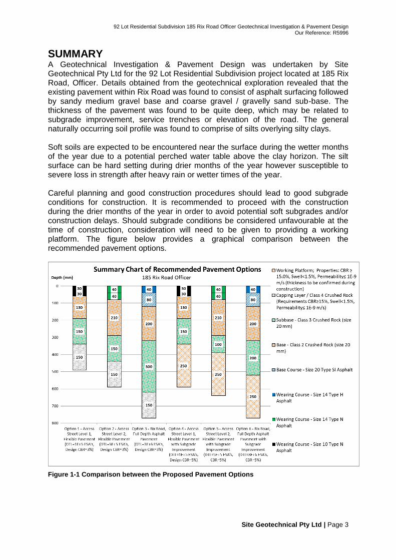
SUMMARY A Geotechnical Investigation & Pavement Design was undertaken by Site Geotechnical Pty Ltd for the 92 Lot Residential Subdivision project located at 185 Rix Road, Officer. Details obtained from the geotechnical exploration revealed that the existing pavement within Rix Road was found to consist of asphalt surfacing followed by sandy medium gravel base and coarse gravel / gravelly sand sub-base. The thickness of the pavement was found to be quite deep, which may be related to subgrade improvement, service trenches or elevation of the road. The general naturally occurring soil profile was found to comprise of silts overlying silty clays. Soft soils are expected to be encountered near the surface during the wetter months of the year due to a potential perched water table above the clay horizon. The silt surface can be hard setting during drier months of the year however susceptible to severe loss in strength after heavy rain or wetter times of the year. Careful planning and good construction procedures should lead to good subgrade conditions for construction. It is recommended to proceed with the construction during the drier months of the year in order to avoid potential soft subgrades and/or construction delays. Should subgrade conditions be considered unfavourable at the time of construction, consideration will need to be given to providing a working platform. The figure below provides a graphical comparison between the recommended pavement options.
Figure 1-1 Comparison between the Proposed Pavement Options
TABLE OF CONTENTS 1 INTRODUCTION ................................................................................................. 5 2 OBJECTIVES AND SCOPE OF WORKS ........................................................... 5
2.1 Field Investigation and Testing Scope of Works ........................................... 5 2.2 Laboratory Testing Scope of Works .............................................................. 5 2.3 Engineering & Reporting Scope of Works ..................................................... 5
3 SITE DESCRIPTION ........................................................................................... 5 3.1 Vegetation ..................................................................................................... 6 3.2 Rock Outcrop ................................................................................................ 6 3.3 Fill ................................................................................................................. 6
8.3 Vegetation ................................................................................................... 25 8.4 General Guide to Good Site Preparation for Placing Fill ............................. 26 8.5 Subgrade Improvement ............................................................................... 27
8.5.1 In Situ Subgrade Stabilisation With Granular Material and Cement ..... 27 8.5.2 Weathered Rock ................................................................................... 27
8.6 Thick Asphalt in the Vicinity of Heavily Trafficked Intersections .................. 28 8.7 General Specifications for Pavement Construction ..................................... 28
8.7.1 Considerations for Pavements Founded on Expansive Subgrades ...... 30 8.8 General Pavement Maintenance & Performance ........................................ 31
9 BIBLIOGRAPHY ............................................................................................... 31 10 VALIDATION ..................................................................................................... 32 11 IMPORTANT INFORMATION ........................................................................... 32
Appendix A –Engineering Log Location Plan ........................................................... 33 Appendix B – Engineering Logs ............................................................................... 34 Appendix C – Laboratory Tests ................................................................................ 35 Appendix D – Circly .................................................................................................. 36 Appendix E – Important Information About Your Geotechnical Engineering Report 42
1 INTRODUCTION This report presents the findings of a Geotechnical Investigation & Pavement Design undertaken by Site Geotechnical Pty Ltd for the 92 Lot Residential Subdivision project located at 185 Rix Road, Officer. The work was commissioned by Beveridge Williams on behalf of AA Holdings Pty Ltd. The investigation was carried out in accordance with our proposal, reference Q5996, dated 23 November 2015.
2 OBJECTIVES AND SCOPE OF WORKS The main objective of this geotechnical investigation is the characterisation of the soil and pavement profile for geotechnical design. The scope of works and methodology adopted has been based on site-specific conditions and information supplied.
2.1 Field Investigation and Testing Scope of Works Characterise the soil profile using visual and tactile assessment generally
complying with AS1726 Geotechnical site investigations.
Perform Dynamic Cone Penetrometer (DCP) tests.
2.2 Laboratory Testing Scope of Works Moisture content on selected samples.
Laboratory soil classification using the Atterberg limits and sieve analysis.
Maximum dry density (MDD) & optimum moisture content (OMC), using standard compactive effort.
Laboratory soaked CBR, using standard compactive effort.
2.3 Engineering & Reporting Scope of Works Prepare a report presenting the factual findings of the investigation together
with comments relating to the design and construction options for the proposed works.
Provide several pavement profile options following relevant guidelines.
Analyse pavement profile options with computer modelling through CIRCLY.
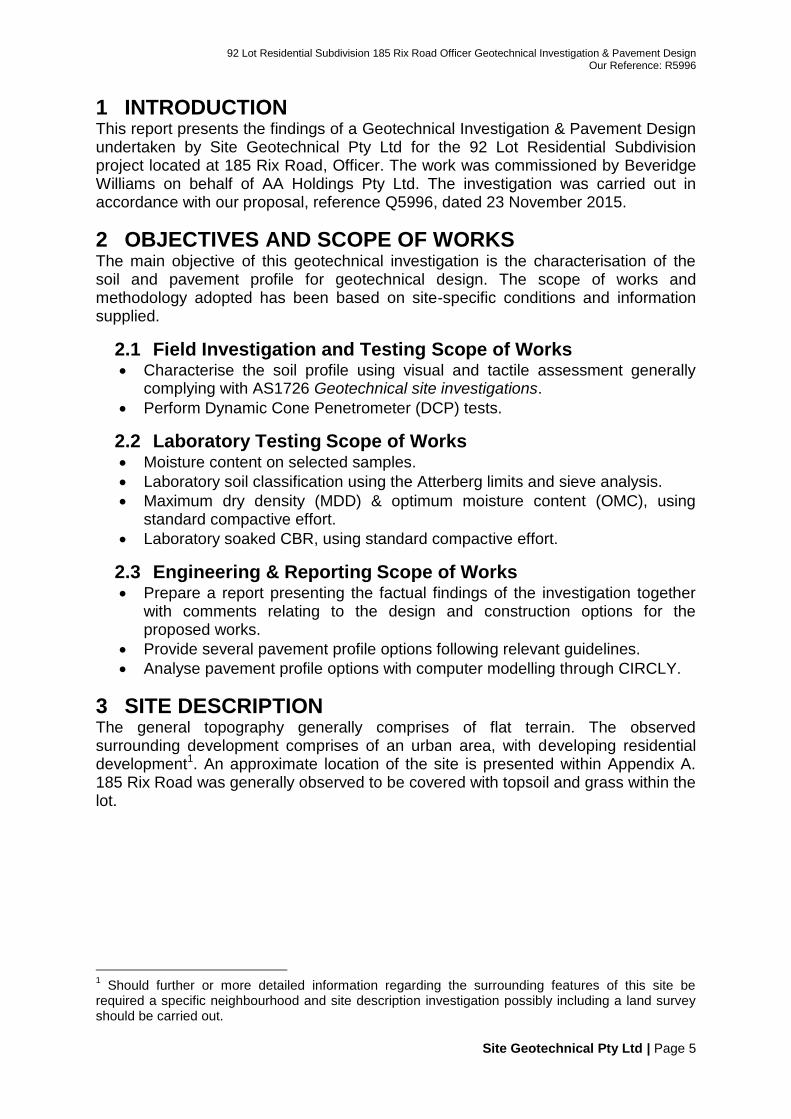
3 SITE DESCRIPTION The general topography generally comprises of flat terrain. The observed surrounding development comprises of an urban area, with developing residential development1. An approximate location of the site is presented within Appendix A. 185 Rix Road was generally observed to be covered with topsoil and grass within the lot.
1 Should further or more detailed information regarding the surrounding features of this site be
required a specific neighbourhood and site description investigation possibly including a land survey should be carried out.
3.1 Vegetation A sparse cover of trees was observed within the site at the time of the investigation. From a structural perspective, trees and shrubs that are allowed to grow in the vicinity of shallow footings, pavements and underground services can cause foundation movement through roots which grow under footings eventually increasing in cross-sectional size and consequently exerting forces on footings or through the roots absorbing moisture and subsequently causing shrinkage or subsidence, particularly within reactive soils. It should also be noted that the removal of trees can also have the opposite effect and for new construction it is preferred that commencement of foundation construction be delayed to allow soil to regain normal moisture conditions. Further advice could be gained from a tree specialist and your structural engineer regarding methods of reducing the effects of tree roots to structures.
3.2 Rock Outcrop Rock outcrops were not observed within the site.
3.3 Fill2 Fill which has been placed under uncontrolled conditions can lead to settlement and/or differential movement. Observations across the site and information collected from the boreholes suggest that the soils within the lot are generally naturally occurring.
2 The presence of fill is normally regarded with caution as it is often associated with high variation in
strength, density and potential for differential settlement. Non-engineered fills (fills with no engineering treatment during deposition) may settle variably and have poor bearing capacity. The extent to which non-engineered fill will be suitable as foundation material depends largely on its age, composition, uniformity, properties and the method by which the material was placed. Therefore with these factors unknown it is recommended that footings and pavements are founded into the naturally occurring soils through the filling where possible.
4.1 Geology Geological information obtained from the Department of Primary Industries indicates that the site is in the geological area of Unnamed alluvium. Geological Polygons 250K Unique Feature Identifier: 4 Map Code: Qa1 Old Map Codes: Qra,Qa,Qrt,Qc Unit Type: Rock Rank: Formation Unit Name: Unnamed alluvium Youngest Age: Quaternary (Holocene) Oldest Age: Quaternary (Holocene) Classification or Environment: Sedimentary (Non-Marine (Alluvial)) Feature Type: ROCK_UNIT Subtype: Sedimentary Lithological Description: Fluvial: alluvium, gravel, sand, silt Area Square Metres: 112225167.95 Hectares: 11222.52 Full Reference: VANDENBERG, A.H.M., 1997. QUEENSCLIFF SJ
55-9 Edition 2, 1:250 000 Geological Map Series 1:250,000 geological map. Geological Survey of Victoria.
Layer 4 - Silty clay Detailed engineering logs are attached within Appendix B. The figures below represent a general graphical summary of the underlying soil profiles encountered.
Figure 4-1 General soil profile
4.3 Groundwater Water exists in different forms and in different places and for widely varying times in the hydrologic cycle. Groundwater or soil moisture content depends on several factors such as permeability, infiltration rate, plant use, hydraulic gradient and surface runoff and evapotranspiration (Delleur, 1999). Observations during drilling revealed a localised evidence of groundwater where borehole 03 revealed soft and wet clay below 0.6 m depth. Should further or more detailed information regarding groundwater at this site wish to be obtained a specific groundwater investigation including surveying, the installation of piezometers, periodic monitoring, and groundwater bore licensing (where required) should be carried out.
5 LABORATORY TESTING Laboratory testing was undertaken on selected samples. The laboratory testing was carried out in general accordance with the Australian Standard AS1289 including Methods of Testing Soils for Engineering Purposes and are presented within the appendixes. A summary of the laboratory test results are presented within the tables below:
Table 5-1 Particle size distribution
Table 5-2 Atterberg limits and soil classification
Where: LL = Liquid Limit, PL = Plastic Limit, PI = Plasticity Index, LS = Linear Shrinkage, LCS = Laboratory Classification of Soil, NP= non plastic, N/O= Not obtained
Table 5-3 Maximum Dry Density and Soil Strength
Where Std MDD = Standard Maximum Dry Density, Std OMC = Standard Moisture Content, CBR = California Bearing Ratio
Table 5-5 Comparison of existing pavement materials with quality standards (Class 3 FCR)
Figure 5-2 Comparison of existing pavement materials with quality standards (Class 3 FCR)
Analysis of Results: Comparison of laboratory findings with quality standards revealed that the sample taken within Rix Road is within the limits recommended for Class 2 FCR and 3 FCR.
Sample ID S5996-02C
Sieve Size (mm)
53.000 100 100 100 100 100
37.500 100 100 100 100 100
26.500 100 100 100 100 100
19.000 97 100 95 100 95
13.200 84 95 75 95 75
9.500 71 90 60 90 60
6.700 62
4.750 52 76 42 76 42
2.360 38 60 28 60 28
1.180 27
0.600 20
0.425 17 28 10 28 14
0.300 15
0.150 10
0.075 8 10 2 13 6
Liquid Limit (%) 18
Plasticity Index (%) 1
Note: figures shown in red highlight values outside recommended limits
% Passing
Recommended Grading for Class 3 (size 20mm)
Los Angeles value of 26 or more Los Angeles value of 25 or less
5.2 Recommended Grading Curve for Foam Bitumen Stabilisation
The grading curve of the material to be stabilised should fall within the range recommended by VicRoads.
Table 5-6 Comparison of laboratory findings with Recommended Grading Curve for Foam Stabilisation
Figure 5-3 Material Comparison with Recommended Grading Curve
Analysis of Results: Comparison of laboratory findings with quality standards revealed that the sample is within the limits recommended for foam bitumen stabilisation.
Sample ID S5996-02C
Sieve Size (mm)
53.000 100 100 100
37.500 100 100 100
26.500 100 100 73
19.000 97 100 64
13.200 84
9.500 71 75 44
6.700 62
4.750 52 55 29
2.360 38 45 23
1.180 27 38 18
0.600 20 31 14
0.425 17
0.300 15 27 10
0.150 10 24 8
0.075 8 20 5
Liquid Limit (%) 18 Max n/a
Plasticity Index (%) 1 Max 10%
Vic
Ro
ads
Tab
le 3
08
.05
1
Recommended Grading for
Foam Bitumen Stabilisation% Passing
Note: figures shown in red highlight values outside recommended limits
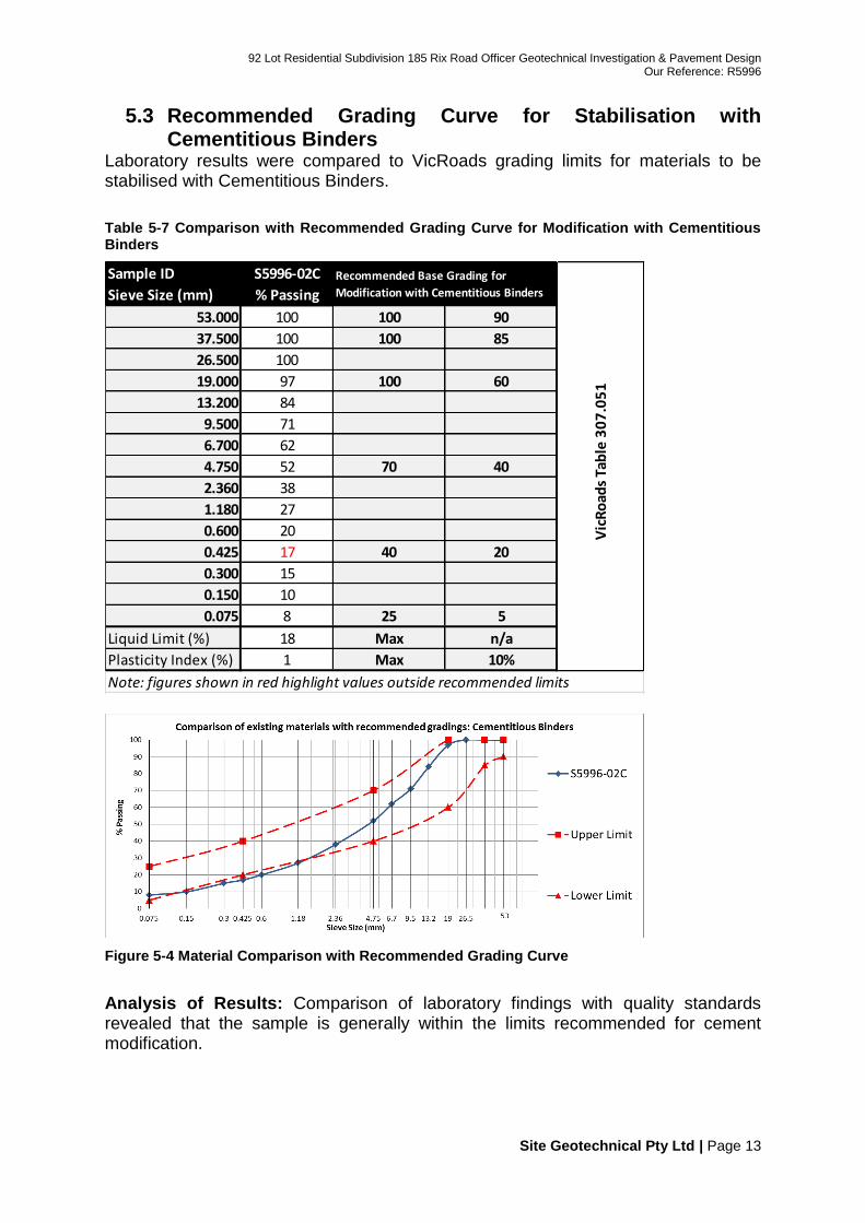
5.3 Recommended Grading Curve for Stabilisation with Cementitious Binders
Laboratory results were compared to VicRoads grading limits for materials to be stabilised with Cementitious Binders.
Table 5-7 Comparison with Recommended Grading Curve for Modification with Cementitious Binders
Figure 5-4 Material Comparison with Recommended Grading Curve
Analysis of Results: Comparison of laboratory findings with quality standards revealed that the sample is generally within the limits recommended for cement modification.
Sample ID S5996-02C
Sieve Size (mm)
53.000 100 100 90
37.500 100 100 85
26.500 100
19.000 97 100 60
13.200 84
9.500 71
6.700 62
4.750 52 70 40
2.360 38
1.180 27
0.600 20
0.425 17 40 20
0.300 15
0.150 10
0.075 8 25 5
Liquid Limit (%) 18 Max n/a
Plasticity Index (%) 1 Max 10%
Vic
Ro
ads
Tab
le 3
07
.05
1
Recommended Base Grading for
Modification with Cementitious Binders% Passing
Note: figures shown in red highlight values outside recommended limits
6 PAVEMENT DESIGN Details obtained from the geotechnical exploration revealed that the existing pavement within Rix Road was found to consist of asphalt surfacing followed by sandy medium gravel base and coarse gravel / gravelly sand sub-base. The thickness of the pavement was found to be quite deep, which may be related to subgrade improvement, service trenches or elevation of the road. The general naturally occurring soil profile was found to comprise of silts overlying silty clays. The upper surface silt/sand can be firm/hard setting during drier months of the year however susceptible to severe loss in strength after heavy rain or wetter times of the year. The thin layers of sands/silts are not preferred as founding material for pavements and/or structural fillings. The pavements and any structural filling are preferred to be founded on the underlying firm/stiff clays.
Table 6-1 Interpretative Subgrade
Layer Comment
Layer 1: sandy medium gravel
Comparison of laboratory findings with quality standards revealed that the sample taken within Rix Road is within the limits recommended for Class 2 FCR and 3 FCR. The sandy gravel with silt may be considered suitable for re-use as sub-base, subgrade improvement or mixed with binders to form a modified material with higher levels of strength and performance.
Layer 2: coarse gravel / gravelly sand
The coarse gravel / gravelly sand may be considered suitable for re-use as lower sub-base or subgrade improvement.
Layer 3: silt These materials may be susceptible to a seasonal or perched water table above the underlying clay horizon which may cause soil weakening. Should a seasonal or perched water table be encountered during construction it is likely to cause construction difficulties (including trench collapse for example). To minimise the potential influences from excessive moisture caused by a perched water table an appropriately installed subsurface drain should be installed or considered. Where these soils are encountered close to the surface, it is often preferred to found pavements into the underlying cohesive clay soils where possible.
Layer 4: silty clay
Fair to good subgrade support was recorded during our site investigation. These soils were generally described as stiff and very stiff. Field CBR’s were found to be generally between 4% and 10+%. Laboratory soaked CBR values were determined to be between 2.5% and 3.5%. The lower laboratory soaked CBR highlights the loss of strength that these materials can experienced with increments in moisture content.
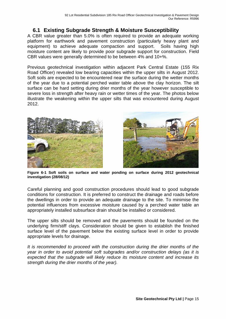
6.1 Existing Subgrade Strength & Moisture Susceptibility A CBR value greater than 5.0% is often required to provide an adequate working platform for earthwork and pavement construction (particularly heavy plant and equipment) to achieve adequate compaction and support. Soils having high moisture content are likely to provide poor subgrade support for construction. Field CBR values were generally determined to be between 4% and 10+%. Previous geotechnical investigation within adjacent Park Central Estate (155 Rix Road Officer) revealed low bearing capacities within the upper silts in August 2012. Soft soils are expected to be encountered near the surface during the wetter months of the year due to a potential perched water table above the clay horizon. The silt surface can be hard setting during drier months of the year however susceptible to severe loss in strength after heavy rain or wetter times of the year. The photos below illustrate the weakening within the upper silts that was encountered during August 2012.
Figure 6-1 Soft soils on surface and water ponding on surface during 2012 geotechnical investigation (28/08/12)
Careful planning and good construction procedures should lead to good subgrade conditions for construction. It is preferred to construct the drainage and roads before the dwellings in order to provide an adequate drainage to the site. To minimise the potential influences from excessive moisture caused by a perched water table an appropriately installed subsurface drain should be installed or considered. The upper silts should be removed and the pavements should be founded on the underlying firm/stiff clays. Consideration should be given to establish the finished surface level of the pavement below the existing surface level in order to provide appropriate levels for drainage. It is recommended to proceed with the construction during the drier months of the year in order to avoid potential soft subgrades and/or construction delays (as it is expected that the subgrade will likely reduce its moisture content and increase its strength during the drier months of the year).
Should subgrade conditions be considered unfavourable at the time of construction, consideration will need to be given to providing a working platform. Proven methods of constructing adequate working platforms within clays of high plasticity include the construction of a subgrade which incorporates the use of subgrade stabilisation (utilising cement), drainage blankets or the use of highly or extremely weathered rock. Preferably the requirements for subgrade improvement should be discussed with the client, superintendent, contractor and Site Geotechnical at the time of construction. The subgrade improvement treatments offer two basic functions: 1) the provision of low plasticity material cover over expansive subgrades to minimise potential environmental effects (where these materials are applied for the full depth) and 2) to provide a subgrade with additional strength consequently providing an adequate working platform to allow construction to proceed (particularly within road reserve areas where a reasonably high degree of construction trafficking may be required for the delivery of fill materials).
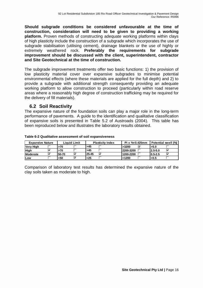
6.2 Soil Reactivity The expansive nature of the foundation soils can play a major role in the long-term performance of pavements. A guide to the identification and qualitative classification of expansive soils is presented in Table 5.2 of Austroads (2004). This table has been reproduced below and illustrates the laboratory results obtained.
Table 6-2 Qualitative assessment of soil expansiveness
Comparison of laboratory test results has determined the expansive nature of the clay soils taken as moderate to high.
Expansive Nature
Very High >70 >3200 >5.0
High >70 2200-3200 2.5-5.0
Moderate 50-70 1200-2200 0.5-2.5
Low <50 <1200 <0.5
>45
>45
25-45
<25
Potential swell (%)Liquid Limit PI x %<0.425mmPlasticity Index
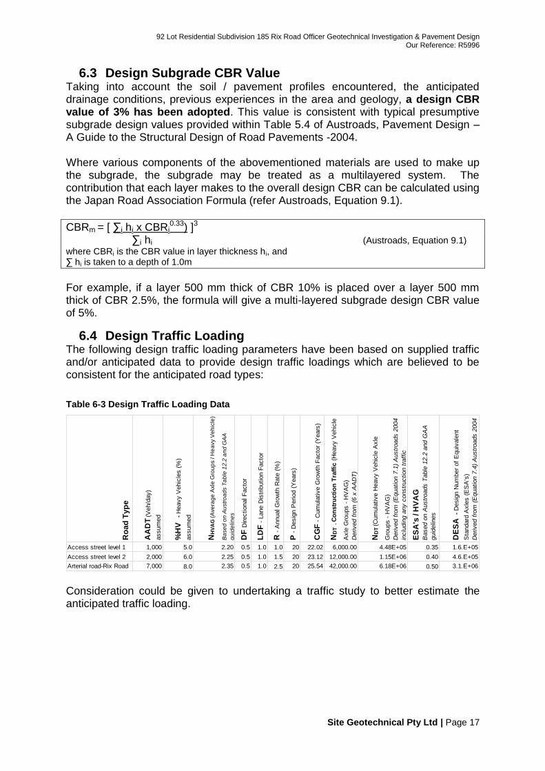
6.3 Design Subgrade CBR Value Taking into account the soil / pavement profiles encountered, the anticipated drainage conditions, previous experiences in the area and geology, a design CBR value of 3% has been adopted. This value is consistent with typical presumptive subgrade design values provided within Table 5.4 of Austroads, Pavement Design – A Guide to the Structural Design of Road Pavements -2004. Where various components of the abovementioned materials are used to make up the subgrade, the subgrade may be treated as a multilayered system. The contribution that each layer makes to the overall design CBR can be calculated using the Japan Road Association Formula (refer Austroads, Equation 9.1).
CBRm = [ ∑i hi x CBRi0.33) ]3
∑i hi (Austroads, Equation 9.1)
where CBRi is the CBR value in layer thickness hi, and ∑ hi is taken to a depth of 1.0m
For example, if a layer 500 mm thick of CBR 10% is placed over a layer 500 mm thick of CBR 2.5%, the formula will give a multi-layered subgrade design CBR value of 5%.
6.4 Design Traffic Loading The following design traffic loading parameters have been based on supplied traffic and/or anticipated data to provide design traffic loadings which are believed to be consistent for the anticipated road types:
Table 6-3 Design Traffic Loading Data
Consideration could be given to undertaking a traffic study to better estimate the anticipated traffic loading.
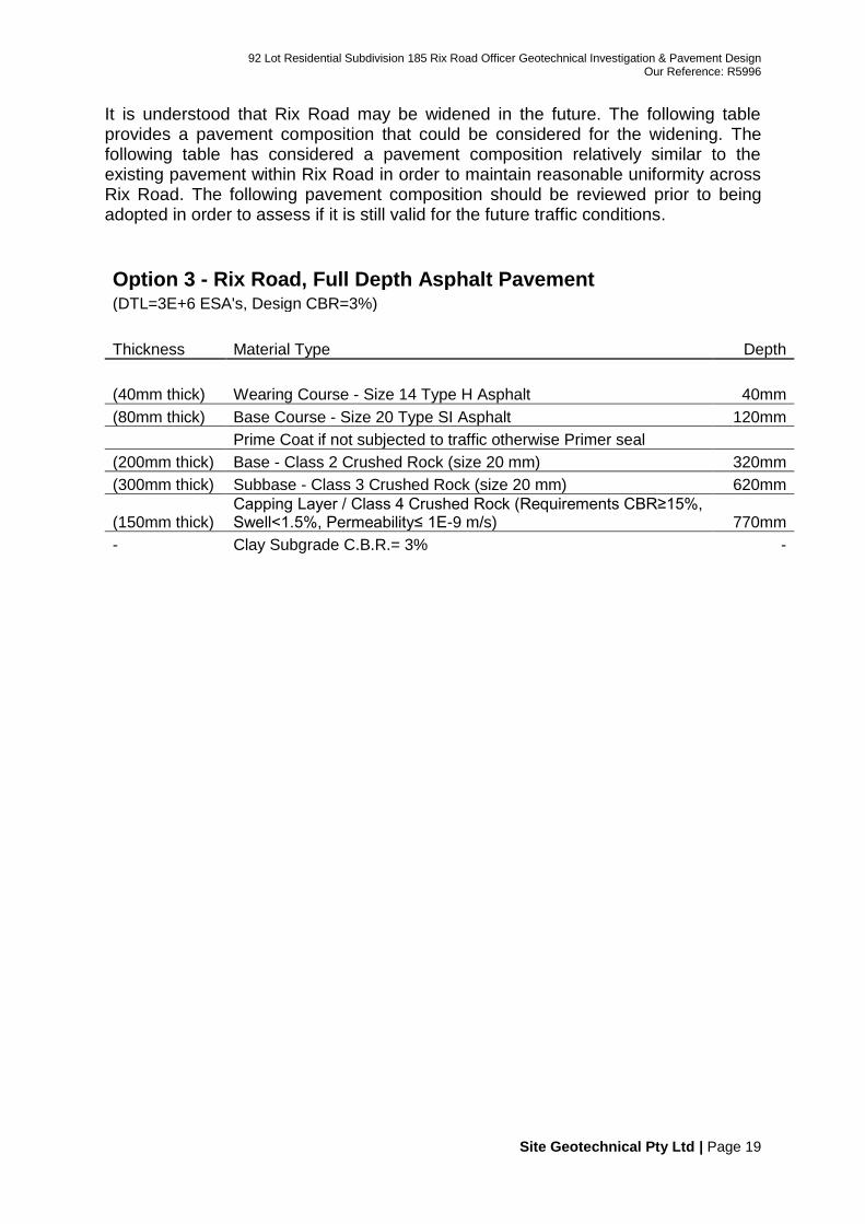
It is understood that Rix Road may be widened in the future. The following table provides a pavement composition that could be considered for the widening. The following table has considered a pavement composition relatively similar to the existing pavement within Rix Road in order to maintain reasonable uniformity across Rix Road. The following pavement composition should be reviewed prior to being adopted in order to assess if it is still valid for the future traffic conditions.
6.5.1 Recommendations for Soft Ground Conditions during Construction
Should poor/soft ground conditions be encountered at the time of construction, consideration will need to be given to providing a working platform. Depending on the extension of the soft soils, different approaches could be considered:
a) Where localised areas present soft ground conditions during construction, consideration could be given to over excavate the subgrade and backfill with a suitable stronger material3 or in-situ stabilise4 the underlying clays with granular material and cement in order to provide a working platform. Then, the pavement options described within the previous section5 can proceed to be built.
b) In large areas presenting soft ground conditions during construction and
subgrade improvement has been undertaken, a reduction of the pavement thickness can be considered to be practical to the whole as the subgrade improvement increases the overall subgrade strength. The following options provide pavement recommendations where subgrade improvement is required to be undertaken in a large scale.
c) VicRoads RC500.22 states that “Lime stabilised material meeting the
requirements of Type A fill including permeability criteria and Section 7.4 of this Code may be used as a capping layer.” It is understood that the City of Casey have had good experience with Lime and Cement stabilised subgrades in the past and would prefer to use stabilisation over and above an imported capping layer. Consideration could be given to utilising some of the existing pavement material together with the underlying clays and cementitious additive to create a suitable working platform / capping layer. Past experience has found that 50% granular material with 50% clay together with 3% GP cement has worked well. Commonly used stabilisation treatments including 3% lime and 3% cement have successfully been used within clay soils in the past.
3 E.g. Class 4 crushed rock (size 40 mm) or soft weathered rock
4 Upper silts/sands and/or over wet materials are not recommended for in-situ stabilisation.
5 Small areas having soft soils: it is more convenient to keep consistency of the pavement
composition across the site after the subgrade improvement has been carried out in localised areas.
Option 6 - Rix Road, Full Depth Asphalt Pavement with Subgrade Improvement (DTL=3E+6 ESA's, Design CBR=5%)
Thickness Material Type Depth
(40mm thick) Wearing Course - Size 14 Type H Asphalt 40mm
(80mm thick) Base Course - Size 20 Type SI Asphalt 120mm
Prime Coat if not subjected to traffic otherwise Primer seal
(200mm thick) Base - Class 2 Crushed Rock (size 20 mm) 320mm
(200mm thick) Subbase - Class 3 Crushed Rock (size 20 mm) 520mm
(250mm thick)
Working Platform; Properties: CBR ≥ 15.0%, Swell<1.5%, Permeability≤ 1E-9 m/s (thickness to be confirmed during construction) 770mm
- Clay Subgrade C.B.R.= 3% -
Matching In – Widening and / or lengthening of existing pavements is common practice however the treatment of the joint or interface between the existing pavement and new (i.e. widening) pavement area can be easily overlooked. Previous experience has shown that where treatment of “joints” has not been paid particular attention, they have regularly displayed cracking between the existing pavement and new area. The reason for this cracking can be numerous and is generally attributed to differential movement between the existing pavement and new area or a construction joint. An important feature of the widening works will be to have its construction match in well with the existing pavement works. For adequate keying-in to be achieved, the widening and the existing pavement should be benched with an aim to eliminating or at least minimising any cracking occurring between the new construction and the widening. Cracking between existing pavements and new pavements can be minimised through the use of pavement materials with similar properties, the use of suitable boxing out procedures, provision of a uniform overlay layer over both the widening and existing pavement (which provides cover to prevent cracking) and the use of geotextiles. Pavement Jointing Details At the joint between the existing and new pavements, stepping the pavement layers should be used to 'tie in' the two pavements. The stepped pavement joints should be constructed in accordance with VicRoads' Standard Specifications for Roadworks and Bridgeworks - Section Clauses 304.06 and 407.16. The installation of subsurface drainage at the joint, should be in accordance with VicRoads Technical Bulletin 32 - Drainage of Subsurface Water from Roads.
6.5.2 Pavement Profile Specifications for Construction An important aspect for every design is the construction. The pavement profile recommendations provided within this report require certain specifications to be implemented in order to assure a satisfactory construction and long-term performance. The following list illustrates the requirements for the pavement profile recommendations provided within this report. Subgrade preparation for pavement construction
Where groundwater or seepage is encountered, the Contractor shall notify the Superintendent and any action to be taken shall, unless otherwise specified, be submitted to the Superintendent for review. The Contractor shall not commence placing any fill on the prepared areas until the Superintendent has inspected these areas and has given consent to proceed. Areas upon which pavements are to be constructed shall be prepared for test rolling by the Contractor. The surface of the prepared area shall be test rolled and any unstable areas detected by test rolling shall be rectified.
Subgrade Improvement
Should subgrade conditions be considered unfavourable at the time of construction, consideration will need to be given to providing a working platform. Preferably the requirements for subgrade improvement should be discussed with the client, superintendent, contractor and Site Geotechnical at the time of construction.
Capping layer material
Consideration could be given to utilising some of the existing pavement material together with the underlying clays and cementitious additive to create a suitable working platform / capping layer. Past experience has found that 50% granular material with 50% clay together with 3% GP cement has worked well. Commonly used stabilisation treatments including 3% lime and 3% cement have successfully been used within clay soils in the past. Alternatively, consideration can be given to importing the capping layer.
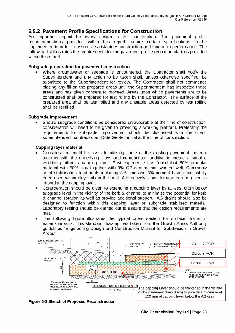
Consideration should be given to extending a capping layer by at least 0.5m below subgrade level in the vicinity of the kerb & channel to minimise the potential for kerb & channel rotation as well as provide additional support. AG drains should also be designed to function within this capping layer or subgrade stabilized material. Laboratory testing should be carried out to assure that the design requirements are met.
The following figure illustrates the typical cross section for surface drains in expansive soils. This standard drawing has taken from the Growth Areas Authority guidelines “Engineering Design and Construction Manual for Subdivision in Growth Areas”.
Figure 6-2 Sketch of Proposed Reconstruction
Class 2 FCR
Class 3 FCR
Capping Layer
Min 150 mm
The capping Layer should be thickened in the vicinity of the pavement drain (kerb) to provide a minimum of
6.6 Graphical Representation of Proposed Pavements The figure below provides a graphical comparison between the recommended pavement options.
Figure 6-3 Comparison between the Proposed Pavement Options
7 PAVEMENT RECOMMENDATIONS It is recommended that Site Geotechnical review plans and specifications
related to geotechnical engineering to assure that the analysis and recommendations provided within this report are properly implemented.
Site Geotechnical should be engaged to undertake site visits (together with the building surveyor or superintendent of the project) during construction.
Laboratory tests of the pavement materials should be undertaken during construction.
8.1 Design Prior to adopting pavement options and earthworks a survey of the site should
be carried out to determine any constraints related to the treatment including (however not limited to) fixed level constraints, existing cross fall compared with desired cross fall, depth of underground services which may otherwise incur damage during excavation and/or compaction works.
8.2 Drainage To minimise the potential influences from excessive moisture caused by a
perched water table an appropriately installed subsurface drain should be installed or considered.
Consideration should be given to establish the finished surface level of the pavement below the existing surface level in order to provide appropriate levels for drainage. Careful planning and good construction procedures should lead to good subgrade conditions for construction.
8.3 Vegetation It is recommended that landscaping and plating techniques close to roads are
undertaken in accordance with VicRoads Technical Report No. 75 - The Influence of Trees and Shrubs on Pavement Loss of Shape.
8.4 General Guide to Good Site Preparation for Placing Fill Site derived or locally imported materials placed on a suitably prepared surface at this site may be suitable if drainage and construction conditions remain favourable. The risks related to potential construction delays and construction problems are anticipated to be higher should construction take place during wetter times of the year or after heavy rainfall. Where it is impracticable to achieve compaction of the prepared surface, a working platform may provide a suitable foundation for subsequent filling. The performance of earthworks relies on good construction practices for both short term and long term performance. The following guidelines (although not exhaustive) provide general information which will assist in good construction:
Top soil containing grass roots or other organic material should be removed from the area on to which filled soils are expected to be placed.
Removal of weak materials and other unsuitable material as defined within section 4.2 of AS3798 will be required prior to placing controlled fill.
The fill area should be protected from wind and / or water erosion
Construction equipment should be supported on material with an allowable bearing pressure of at least 50kPa, it has often been found that material having a CBR value of less than 5.0% at the time of construction will often cause construction problems. Where soil conditions are considered unfavourable for the placement of filling consideration should be given to providing a working platform which allows construction to proceed.
Fill construction should be adequately compacted and retained or battered and protected from erosion.
Adequate drainage of the site will assist construction and avoid softening or weakening of foundation materials. It should be noted that leaving excavations open during prolonged dry weather can also have a long term effect on fill performance.
Fill material should be placed in near-horizontal layers of uniform thickness, deposited systematically across the fill area. The thickness of each compacted layer should not exceed 200mm where practical.
Detailed guidelines in relation to fill placement are provided within “AS3798 - Guidelines on earthworks for commercial and residential developments”
8.5.1 In Situ Subgrade Stabilisation With Granular Material and Cement It is considered that a mixture of 50% Gravel and 50% Site Derived Clay with approximately 3% GP cement (and lime if required) would be appropriate to meet the project objectives for subgrade improvement. Commonly used stabilisation treatments including 3% lime and 3% cement have successfully been used within clay soils in the past. Additional laboratory testing would be required to ensure that the stabilization objectives are met. Further information relating to in situ stabilisation should be obtained from stabilisation specialists and contractors to determine the most appropriate additive and construction method for the conditions at the time of construction. Stabilisation of materials which are well above optimum moisture content or considered as wet at the time of construction or are non-cohesive (low clay content) may not be considered suitable for stabilisation.
8.5.2 Weathered Rock There are many examples, where selective placement of weathered rock within residential developments has been successfully used in the past as subgrade improvement, where poor subgrade conditions have been encountered. Generally ‘weathered’ material should consist of local or site derived material with the following specification used as a guide:
Minimum Soaked CBR ≥ 15%
Plasticity Index ≤ 45
Swell ≤ 1.5%
Permeability ≤ 5.0 x 10⁻⁷ cm/sec
Practical minimum thickness of 150mm Where weathered rock material is used for filling, the after-compaction quantity of material coarser than 37.5 mm may exceed 20%. With such material, the test procedures for in situ determination of dry density ratio specified in the relevant parts of AS 1289 are not applicable and special consideration should be given to alternative methods of testing for compaction. In such circumstances, it is common to adopt a method specification which may include test rolling. Once an adequate working platform has been established subsequent soil or granular layers could comprise of site derived or locally imported soils.
8.6 Thick Asphalt in the Vicinity of Heavily Trafficked Intersections
Based on previous experience, it is often found beneficial to provide a thick layer of asphalt in the vicinity of roundabouts and heavily trafficked intersections. Evidence from roundabouts and heavily trafficked intersections with relatively thin asphalt surfacings have developed shoving and rutting defects which can be inferred to have been caused from the thin asphalt being structurally weak. To minimise these types of defects it is suggested that a moderately thick asphalt (say at least 80mm thick) be used in the intersection. Say a minimum of 50m from the stop line and extend through the intersection (including the entire length of the turn lane taper) and at least the first 30m of the exit lanes.
8.7 General Specifications for Pavement Construction Asphalt - Asphalt shall conform to the requirements of Australian Standard AS2150 “Asphalt (hot-mixed)” Asphalt shall be supplied, placed and compacted to the minimum thicknesses specified in accordance with the Australian Standard AS 2150 Tack Coat- Consideration should be given to providing a prime (if not subjected to traffic). Otherwise primerseal the finished surface of the base prior to placing the subsequent asphalt. The tack coat should comprise of Class 170 bitumen sprayed at a rate in the order of 1 l/m2 unless otherwise determined by the Contractor on site at the time of application. Granular Material - Granular material shall conform to the requirements of the Local Government / Council or State Road Authority specification for base sub-base or lower sub-base crushed rock. Crushed Rock - Where required, the base, subbase and / or lower subbase material shall be supplied, spread to the required thickness, graded to level and compacted. The minimum compacted density of the material shall be 98% for bases and 95% for subbases and lower subbases or cementitious modified or cemented materials of the (Modified) Maximum Dry Density as determined in accordance with Australian Standard AS1289.5.2.1. Subgrade - Where required, the subgrade will be prepared and graded for the subsequent placement of pavement materials. The minimum compacted density of the subgrade shall be 95% of the (Standard) Maximum Dry Density at a moisture content between 90% and 120% of Optimum Moisture Content as determined in accordance with Australian Standard AS1289.5.1.1. Testing & Quality Control - The Contractor shall undertake or arrange to be undertaken all testing as specified herein. The testing shall be undertaken by a laboratory certified by NATA for the specified test or tests. Testing frequencies of testing shall conform to the requirements of the Local Government / Council or State Road Authority.
Sub-surface Drainage - Where required, sub-surface drains shall be installed at appropriate depths to provide adequate subsurface drainage and yet not be installed too deep (particularly within reactive subgrade sites) to promote effects of drying and shrinkage. These drains should be connected to a free outlet, storm water collection pit, drain or channel. These drains shall meet the relevant authorities requirements, however typically comprise of 100 mm slotted PVC pipe or slotted flexible polyethylene pipe and shall be laid in trenches of 200 mm width, which shall be backfilled to the appropriate level using filter materials. Further recommendations regarding the selection of filter material can be found within VicRoad specifications Section 702 - Subsurface Drainage Further advice on subsurface drainage can be found in Technical Bulletin 32 - Drainage of subsurface water from roads. Matching In – Widening and / or lengthening of existing pavements is common practice however the treatment of the joint or interface between the existing pavement and new (i.e. widening) pavement area can be easily overlooked. Previous experience has shown that where treatment of “joints” has not been paid particular attention, they have regularly displayed cracking between the existing pavement and new area. The reason for this cracking can be numerous and is generally attributed to differential movement between the existing pavement and new area or a construction joint. An important feature of the widening works will be to have its construction match in well with the existing pavement works. For adequate keying-in to be achieved, the widening and the existing pavement should be benched with an aim to eliminating or at least minimising any cracking occurring between the new construction and the widening. Cracking between existing pavements and new pavements can be minimised through the use of pavement materials with similar properties, the use of suitable boxing out procedures, provision of a uniform overlay layer over both the widening and existing pavement (which provides cover to prevent cracking) and the use of geotextiles. Pavement Jointing Details At the joint between the existing and new pavements, stepping the pavement layers should be used to 'tie in' the two pavements. The stepped pavement joints should be constructed in accordance with VicRoads' Standard Specifications for Roadworks and Bridgeworks - Section Clauses 304.06 and 407.16. The installation of subsurface drainage at the joint, should be in accordance with VicRoads Technical Bulletin 32 - Drainage of Subsurface Water from Roads.
8.7.1 Considerations for Pavements Founded on Expansive Subgrades For the construction of new pavements or existing pavements constructed on expansive subgrades, consideration should be given to section 5.3.5.1 of the Austroads Pavement Design Guide (2004). This section provides several strategies on how to minimise volume changes in expansive soils, some items which may reflect causes of cracking at this site include the following items:
Compaction of soil at equilibrium moisture content.
Compaction should be adequate and be conducted at the appropriate moisture content otherwise the pavement is likely to suffer from differential movement and cracking.
Ensure that the location of pavement drains is confined to the impermeable subbase and does not extend into the expansive soils.
Anecdotal evidence indicates that it is common practice is to install these drains well within the expansive soils. Deep subsurface drainage within an expansive subgrade is likely to cause differential moisture changes – particularly within the outer wheel path. Drains located within expansive soils have been known to cause fluctuations in the moisture content of the soil, and has been highlighted within observations undertaken within Glinden and Chatsworth Avenue where longitudinal cracking was extensively observed close to the outer wheel path of rehabilitated areas, however not so extensively observed within existing (untreated) sections of Glinden and Chatsworth Avenue.
The figure above represents a pictorial illustration of longitudinal cracking observed with the rehabilitated pavement within Chatsworth Avenue.
Restrict the planting of trees and shrubs close to the pavement.
Consideration could be given to planting trees which are less likely to cause damage, installing root barriers or providing irrigation to minimise the roots search/extent for moisture.
Consider minimum cover requirements for expansive subgrade soils.
VicRoads Technical Bulletin No. 37 and VicRoads Code of Practice RC 500.22 provide recommendations for minimum cover over expansive subgrades. The required cover increases with traffic loading to reflect better ride quality on higher traffic volume roads. The minimum recommended overall pavement depth recommended for a design traffic loading of 1x10⁵
ESA’s is 400mm according to the abovementioned requirements.
Appropriate design of cross - section.
Consideration should be given to extending a capping layer by 1.0m outside the edge of traffic lanes to minimise moisture changes, particularly under the outer wheel paths, with careful consideration of subsurface drainage also requiring attention.
8.8 General Pavement Maintenance & Performance The recommended pavement designs for flexible pavements within this report are based on the performance requirement that significant damage can be avoided, provided that foundation site conditions are properly maintained. Maintenance of pavements should include maintaining stable moisture conditions and will require attention to the following items:
Drainage of the site
Limitations on over-wetting and drying
Restrictions on trees and shrubs
Repair of any surface deficiencies (including crack sealing) and strengthen any distressed areas.
The probability for failure for reasonable site conditions is low, but higher if extreme conditions are encountered. It is not considered possible nor economical to design for extreme conditions that could occur in the foundation if a site is not properly maintained. In some cases designers, constructors or asset owners may consider to undertake additional precautionary measures within their pavement design where extremes of wetting and drying for example, cannot be economically protected against by undertaking maintenance measures alone. The level to which these measures are implemented should be based on site conditions, reactivity of the site and the type of construction. This report applies to normal sites.
9 BIBLIOGRAPHY Austroads (2004), A Guide to the Structural Design of Road Pavements
Austroads (1998), A Guide to the design of new pavements for light traffic, APRG Report No. 21.
Delleur, J. (1999) The Handbook of Groundwater Engineering. CRC Press LLC 2000 Corporate Blvd., N.W. Boca Raton, FL 33431, U.S.A.
Department of Primary Industry (2007), Geology Map, GeoVic.
Glade et al (2005), Landslide Hazard and Risk John Wiley & Sons Ltd, The Atrium, Southern Gate, Chichester, West Sussex PO19 8SQ, England.
Hunt, R. (2007), Geologic Hazards, A Field Guide for Geotechnical Engineers. CRC Press Taylor & Francis Group, USA
Look, B. (2007), Handbook of Geotechnical Investigation and Design Tables. Taylor & Francis Group, London, UK
Standards Australia (1993), Geotechnical site investigations, AS1726
Standards Australia (2007), Guidelines on earthworks for commercial and residential developments, AS 3798.
VicRoads (2004), Code of Practice for Selection and Design of Pavements and Surfacings, RC 500.22.
10 VALIDATION Collection of information and its appraisal, should continue during any construction works, to confirm or otherwise the assumed ground model. In this case it may be preferred that the geotechnical consultant assess and monitor the ground conditions during construction, particularly in light of potentially poor or variable ground conditions or unexpected findings.
11 IMPORTANT INFORMATION Ownership of the data collected and recorded by Site Geotechnical and any specialist testing remains with Site Geotechnical Pty Ltd until all amount owing to Site Geotechnical Pty Ltd by the client are fully discharged. This report has been prepared for the particular project described and no responsibility is accepted for the use of any part of this report in any other context or for any other purpose. Copyright in this report is the property of Site Geotechnical Pty Ltd. The client and / or its representatives alone shall have a license to use this report. This report shall not be reproduced except in full. Soil and rock exploration and testing have inherent uncertainties. Thus your attention is drawn to limitations inherent in the extrapolation of the limited subsurface information obtained from the site, which is further discussed within the last appendix. Should you have any queries or comments regarding this report please feel free to contact the undersigned. Regards, ……………………………………………... ……………………………………………... Report reviewed by:- Report written by:- Nael Yassi B.E. (Civil) Hons. Geotechnical Engineer
Title:- 92 Lot Residential Subdivision 185 Rix Road - Officer Plan Not to Scale (Plan source: Supplied by Client) Pins show approximate borehole locations
Appendix E – Important Information About Your Geotechnical Engineering Report INTRODUCTION The purpose of this document is related to subsurface conditions, and to address the variable nature of soil and rock materials when used as a foundation or construction material. This information should be of benefit to Owners, Developers, Geotechnical, Design and Construction personnel. Early recognition of geotechnical problems during the design stage is still the best way to reduce the risk of geotechnical construction problems and thereby bid prices. This normally means conducting an adequate desktop study and subsurface investigation in advance of final design for a particular project. The complete disclosure of available subsurface information in the contract documents is also an important factor in both preventing contractor claims and in obtaining fair bids for the work to be performed. Matters which could influence the project may include, however may not be limited to, easements, site features, slope stability, acid sulphate soils (ASS), mining subsidence and earthquakes. Undertaking a desktop study, such as a review of management overlays, may recognise potential problems associated with the site which may require particular attention. The amount of desktop study and subsurface information actually presented and the method of presentation in the geotechnical report can vary depending on client requirements and the complexity of the project. It should be noted that not all the information provided here is necessarily relevant to all types of our reports and that Geoenvironmental concerns are not covered. ENGINEERING REPORTS Professional judgments and recommendations are presented in this report. They are based partly on evaluation of the technical information gathered, partly on historical reports (where obtained) and partly on our general experience with subsurface conditions in the area. It should be noted that the borings may not represent potentially unfavourable subsurface conditions between borings. If during construction soil conditions are encountered that vary from those discussed in this report or other reports or if design loads and/or configurations change, we should be notified immediately in order that we may evaluate effects, if any, on foundation performance. The recommendations presented in this report are applicable only to this specific site. The data provided should not be used for other purposes, where the report has been prepared for a specific design proposal as the information and interpretation may not be relevant. Nevertheless Site Geotechnical will be pleased to review the report and the sufficiency of the investigation work for other purposes, and discuss any further information which may be required. ENGINEERING LOGS The engineering logs are an interpretation of the subsurface condition, and their reliability will depend to some extent on the frequency of sampling and the method of excavation. The descriptions of the soils found closely follow those outlined in AS1726-1993, Geotechnical Site Investigations.
FILL The presence of fill materials can often be determined by the visual inspection of foreign objects (i.e. building rubble) or by distinctly unusual smell, texture or colour. Where natural soils similar to those at the site are used for fill, it may be difficult to readily determine the extent of fill, and test pits are often preferred over boreholes to determine their extent. The presence of fill is normally regarded with caution as it is often associated with high variation in strength and density and potential for differential settlement which can often be associated with higher construction costs to minimise its effect to a particular project unless it can be proven and/or documented that the fill materials have been placed under controlled conditions. POTENTIAL FOR DIFFERING SITE CONDITIONS Subsurface conditions at a particular site are the result of natural geologic processes modified in time by physical events, such as erosion, or by man. Site Geotechnical Pty Ltd routinely provides subsurface information to their clients in good faith to permit a general appraisal of below ground conditions. However unanticipated latent ground conditions can and do occur. SHOULD DIFFERING SITE CONDITIONS BE ENCOUNTERED During the progress of the work, if subsurface or physical conditions are encountered at the site differing materially from those indicated in the geotechnical report or if unknown physical conditions of an unusual nature, differing materially from those ordinarily encountered and generally recognized as inherent in the work provided for the project are encountered at the site, the party discovering such conditions shall promptly notify Site Geotechnical Pty Ltd in writing of the specific differing conditions before the site is disturbed and before the affected work is performed. Changes in ground such as filling, nearby construction or by natural events such as flooding which has occurred after the engineering logs were completed, are an example of a differing site condition at or above ground level, in which case Site Geotechnical should be contacted before applying the report to determine if it is still relevant. A minor amount of additional investigation could prevent major problems. Site Geotechnical Pty Ltd will not be responsible for any financial losses (consequential or otherwise) that may result from required changes and / or revised report recommendations. KEEP IN TOUCH WITH YOUR CONSULTANT (SITE GEOTECHNICAL PTY LTD) Recommendations provided within our report are not necessarily final. It is often found with the passage of time that more information is gathered related to a specific site or project and it is often beneficial to have a geotechnical engineer available to undertake construction observations and undertake meetings with design members and contractors to minimise misinterpretation and risk related to geotechnical issues.