HYDROLOGICAL PROCESSES Hydrol. Process. 24, 1548–1566 (2010) Published online 24 March 2010 in Wiley InterScience (www.interscience.wiley.com) DOI: 10.1002/hyp.7634 Soil piping and catchment response J. A. A. Jones* Institute of Geography and Earth Sciences, Aberystwyth University, SY23 3DB, UK Abstract: Over the 40 years, since soil piping was first considered to be a potential factor in the hydrological response of catchments, research has revealed a considerable amount about its hydrological role and its geographical, climatic and pedological distribution. Piping has been shown to be a major factor supporting the hypothesis that subsurface flow can be a significant contributor to quickflow by field experiments ranging from the United Kingdom to Canada, India and China. This research has demonstrated that, at least in some areas, soil pipes may contribute up to nearly 50% of stormwater discharge. Piping processes therefore merit inclusion within rainfall–runoff simulation models, but this has yet to be achieved. Some progress has been made in modelling pipeflow itself, but integration within a catchment model presents major problems, not least in quantifying or parameterizing the nature and distribution of pipe networks. The wider environmental implications of soil piping are also only just beginning to be recognized. These range from the effects of changing residence times on water chemistry, especially on the acidification of surface waters, to the effects of hillslope drainage patterns on soil development and vegetation diversity. Copyright 2010 John Wiley & Sons, Ltd. KEY WORDS soil piping; pipeflow; quickflow; throughflow; catchment response contributing areas Received 27 August 2009; Accepted 26 January 2010 BACKGROUND The concept of preferential flow is now a dominant theme in hillslope hydrology, as the session on hydrological connectivity on hillslopes at the San Francisco meeting of the American Geophysical Union in December 2009 and the earlier conference on preferential flow held by the American Society of Agricultural and Biological Engi- neers (Bosch and King, 2001) demonstrate. Uhlenbrook (2006) went so far as to suggest that all hillslope drainage is preferential. Weiler and McDonnell (2007) state that one of the greatest challenges in hillslope hydrology is conceptualizing and parameterizing lateral subsurface preferential flow, which current physically based and con- ceptual models often ignore. They point out that, in order to obtain models that are capable of predicting the effects of land use change, it is important to identify the domi- nant hydrological processes. One might add that another, perhaps, even more important application of such mod- els is to predict the effects of climate change on basin response (Pilling and Jones, 2002). This paper is devoted to just one of these subsurface pathways: soil pipes. Soil pipes are the largest category of macropore and have the potential to provide net- works with the greatest connectivity. Beven and Germann (1982) drew special attention to the role of macropores in causing bypass flow (bypassing the soil matrix) and identified soil pipes as macropores that are sufficiently large for water to sculpt their form. This offers a work- able, visual means of defining a pipe. However, the exact * Correspondence to: J. A. A. Jones, Institute of Geography and Earth Sciences, Aberystwyth University, SY23 3DB, UK. E-mail: [email protected]point at which a macropore becomes a water-sculpted pipe is elusive and variable, depending particularly on soil properties and hydraulic gradients. Jones (1987a) attempts to answer this question, making particular use of the work of engineers concerned with the stability of earth dams. The Australian engineer Ingles (1968) sug- gests that submicrometre-size particles can be eroded by throughflow velocities associated with permeabilities as low as 10 4 mm s 1 , but in soils bonded in silt-size particles permeabilities in excess of 10 1 mm s 1 are needed. Both thresholds have been advanced as critical for the onset of piping erosion in earth dams. Turbu- lent flow is not a prerequisite for erosional development, although it is clearly the more effective. Field observa- tions reported by Jones and Crane (1984) suggest that no flows within small ephemerally flowing pipes (<50 mm diameter) were unequivocally turbulent with Reynolds numbers <300. By contrast, 4% of flows in larger peren- nial pipes (250 mm in diameter) were turbulent, and sed- iment traps in these pipes suggest that they could be the source of 15% of the annual sediment discharge from the basin. A degree of confusion has recently been introduced by Weiler et al. (2003) and Weiler and McDonnell (2007), who propose their own definition of soil pipes which is at variance with established definitions (cp. Jones, 1981). This is in no way a criticism of the otherwise excellent monitoring and modelling work done at the Maimai research catchment in New Zealand. But Weiler and McDonnell restrict the term ‘macropore’ to vertical preferential flow paths and use ‘pipe’ for pathways parallel to the slope. In reality, macropores as defined by Beven and Germann (1982) can be lateral as well Copyright 2010 John Wiley & Sons, Ltd.
Transcript
HYDROLOGICAL PROCESSESHydrol. Process. 24, 1548–1566 (2010)Published online 24 March 2010 in Wiley InterScience(www.interscience.wiley.com) DOI: 10.1002/hyp.7634
Soil piping and catchment response
J. A. A. Jones*Institute of Geography and Earth Sciences, Aberystwyth University, SY23 3DB, UK
Abstract:
Over the 40 years, since soil piping was first considered to be a potential factor in the hydrological response of catchments,research has revealed a considerable amount about its hydrological role and its geographical, climatic and pedologicaldistribution. Piping has been shown to be a major factor supporting the hypothesis that subsurface flow can be a significantcontributor to quickflow by field experiments ranging from the United Kingdom to Canada, India and China. This researchhas demonstrated that, at least in some areas, soil pipes may contribute up to nearly 50% of stormwater discharge. Pipingprocesses therefore merit inclusion within rainfall–runoff simulation models, but this has yet to be achieved. Some progresshas been made in modelling pipeflow itself, but integration within a catchment model presents major problems, not leastin quantifying or parameterizing the nature and distribution of pipe networks. The wider environmental implications of soilpiping are also only just beginning to be recognized. These range from the effects of changing residence times on waterchemistry, especially on the acidification of surface waters, to the effects of hillslope drainage patterns on soil developmentand vegetation diversity. Copyright 2010 John Wiley & Sons, Ltd.
KEY WORDS soil piping; pipeflow; quickflow; throughflow; catchment response contributing areas
Received 27 August 2009; Accepted 26 January 2010
BACKGROUND
The concept of preferential flow is now a dominant themein hillslope hydrology, as the session on hydrologicalconnectivity on hillslopes at the San Francisco meeting ofthe American Geophysical Union in December 2009 andthe earlier conference on preferential flow held by theAmerican Society of Agricultural and Biological Engi-neers (Bosch and King, 2001) demonstrate. Uhlenbrook(2006) went so far as to suggest that all hillslope drainageis preferential. Weiler and McDonnell (2007) state thatone of the greatest challenges in hillslope hydrologyis conceptualizing and parameterizing lateral subsurfacepreferential flow, which current physically based and con-ceptual models often ignore. They point out that, in orderto obtain models that are capable of predicting the effectsof land use change, it is important to identify the domi-nant hydrological processes. One might add that another,perhaps, even more important application of such mod-els is to predict the effects of climate change on basinresponse (Pilling and Jones, 2002).
This paper is devoted to just one of these subsurfacepathways: soil pipes. Soil pipes are the largest categoryof macropore and have the potential to provide net-works with the greatest connectivity. Beven and Germann(1982) drew special attention to the role of macroporesin causing bypass flow (bypassing the soil matrix) andidentified soil pipes as macropores that are sufficientlylarge for water to sculpt their form. This offers a work-able, visual means of defining a pipe. However, the exact
* Correspondence to: J. A. A. Jones, Institute of Geography and EarthSciences, Aberystwyth University, SY23 3DB, UK.E-mail: [email protected]
point at which a macropore becomes a water-sculptedpipe is elusive and variable, depending particularly onsoil properties and hydraulic gradients. Jones (1987a)attempts to answer this question, making particular useof the work of engineers concerned with the stability ofearth dams. The Australian engineer Ingles (1968) sug-gests that submicrometre-size particles can be eroded bythroughflow velocities associated with permeabilities aslow as 10�4 mm s�1, but in soils bonded in silt-sizeparticles permeabilities in excess of 10�1 mm s�1 areneeded. Both thresholds have been advanced as criticalfor the onset of piping erosion in earth dams. Turbu-lent flow is not a prerequisite for erosional development,although it is clearly the more effective. Field observa-tions reported by Jones and Crane (1984) suggest that noflows within small ephemerally flowing pipes (<50 mmdiameter) were unequivocally turbulent with Reynoldsnumbers <300. By contrast, 4% of flows in larger peren-nial pipes (250 mm in diameter) were turbulent, and sed-iment traps in these pipes suggest that they could be thesource of 15% of the annual sediment discharge from thebasin.
A degree of confusion has recently been introduced byWeiler et al. (2003) and Weiler and McDonnell (2007),who propose their own definition of soil pipes whichis at variance with established definitions (cp. Jones,1981). This is in no way a criticism of the otherwiseexcellent monitoring and modelling work done at theMaimai research catchment in New Zealand. But Weilerand McDonnell restrict the term ‘macropore’ to verticalpreferential flow paths and use ‘pipe’ for pathwaysparallel to the slope. In reality, macropores as definedby Beven and Germann (1982) can be lateral as well
Copyright 2010 John Wiley & Sons, Ltd.
SOIL PIPING AND CATCHMENT RESPONSE 1549
as vertical and the critical feature of a pipe is itswater-sculpted form. Weiler and McDonnell also statethat these pipes are either formed by soil fauna or bydead root holes, whereas the classic theory of the origin ofpiping propounded by Terzaghi (1922, 1943) is hydraulic.The notion that pipes are formed primarily by biologicalagents persists in some quarters, e.g. Nieber (undated)who confusingly cites Jones and Connelly’s (2002) workon water-sculpted pipes in Wales in this presentation onbiopores. The actual origins of those pipes, accordingto Jones (1982, 1990), are: desiccation cracks on theupper slopes, mass movement on the mid-slopes andpossibly Terzaghian ‘boiling’ processes on the lowerslopes. Fortunately, Nieber (2006) partially corrects hisearlier view.
Weiler and McDonnell are building upon previousresearch in the Maimai research catchment that has notedthe significance of macropores in generating subsurfacestormflow, but which does not refer explicitly to pipes(Mosley, 1979; McDonnell, 1990). These latter macro-pores are similar to those that Whipkey (1965, 1966)referred to in his classic pioneering work at the USDepartment of Agriculture Northeast (USDA NE) For-est Service Station in Ohio as producing ‘pipe-like’ or‘faucet-like’ outflows in soil pits. At the same station,Aubertin (1971) described it in the same terms. The workof Whipkey and Aubertin gave a major fillip to Hewlett’s(1961) hypothesis of subsurface contributions to streamresponse. However, Aubertin’s diagrams clearly indicatethat he is referring to cracks and biotic holes that showno water sculpting. Weiler and McDonnell (2007) andAubertin (1971) state that the features they observe intheir soil pits are caused by animals, like earthworms,moles or cicadas, plant roots or cracks.
Some confusion is already present in the geomorpho-logical literature between pipes and tunnels, wherebysome maintain that pipes are only hydraulicly formedfeatures and tunnels are features which generally havedifferent origins that have been subsequently molded bywater (Jones, 1981, 1987a). Sherard et al. (1972) rec-ognize ‘rainfall erosion tunnels’ on the surface of earthdams, which may have exploited cracks, as distinct fromhydraulic piping below the phreatic surface. These dis-tinctions are only of relevance to hydrology in so far as:(1) they may relate to the location of the pipes relative toany groundwater or saturated zone, (2) whether the pipesflow full or part-full and (3) whether pipeflow is gener-ated by the hydraulic head vertically above the pipe, asWeiler and McDonnell’s (2007) model assumes, or bythe collection of water from some possibly quite remotelocation further up the hillslope. Weiler and McDonnell’smodel also assumes that these pipes are short and fit into a2-m grid, based on their observations suggesting averagelengths of 2–5 m. In this, they acknowledge that they arenot modelling ‘the continuous, large pipe networks’ mod-elled by Jones and Connelly (2002). Herein lies a danger,that authors may not be comparing like with like.
This paper is concerned with soil pipes as defined andstudied in the Centre for Hydrology and Ecology Upper
Wye subcatchments, the Aberystwyth University Maes-nant catchment and elsewhere in the United Kingdom.
As the most connected form of macropore, soil pipes(as thus defined) are capable of extending the dynamiccontributing area for stream response well beyond thecontiguous riparian zone envisaged in the original con-cept of partial contributing areas Tennesee Valley Author-ity (TVA), 1960; Hewlett, 1961; Betson, 1964; Hewlettand Hibbert, 1967). One British pipe network studiedby the author is 750-m long, beginning as a shallow,ephemerally flowing pipe 150 mm deep, then entering amid-slope bog where resurgent groundwater allows thenetwork to continue to the stream as a perennially flow-ing pipe 500 mm deep (Jones, 1987b). In this particularcatchment, the pipe network is responsible for doublingthe size of the dynamic contributing area compared withcontribution measured from the standard sources of over-land flow and bank seepage (Jones, 1987b). Jones (1979)proposed that pipeflow should be incorporated into anextended form of Hewlett’s (1961) theory of catchmentresponse, an idea taken up by Ward (1980). Jones alsointroduced the concept of a ‘dynamic contributing vol-ume’, extending the established idea of a contributingarea, which owes its origins to surface overland flowtheory (cp. Dickinson and Whiteley, 1970), into the thirddimension to incorporate the volume of soil contributingthroughflow and pipeflow.
The potential role of soil piping in accelerating sub-surface flow was first highlighted by British researchers.Jones (1971) reported the discovery of soil piping in thebanks of the Burbage Brook catchment, a tributary of theRiver Derwent in the English Peak District, in 1968, andspeculated on its possible role in streamflow response andin stream channel extension through pipe enlargementand roof collapse (Jones, 1987a). The first attempts toquantify its role in streamflow response were made in theearly 1970s in the Cambrian Mountains of mid-Wales byJones (1975, 1978) in the Maesnant basin and by mem-bers of the Institute of Hydrology in the adjacent UpperWye catchment (Gilman and Newson, 1980). The lat-ter included unpublished data collected during Gilman’smonitoring experiments in 1971 and 1972 on selectedslopes within the catchment. On the basis of the evi-dence collected in these initial studies, Newson (1976)and Jones (1978) called for more research to be focussedon pipeflow contributions.
The first catchment scale monitoring programme wasundertaken in the Maesnant catchment, 1979–1982. Thiswas followed by further monitoring programmes in thecatchment funded by the Natural Environment ResearchCouncil (NERC) up to the early 1990s, one attached tothe Department of Environment funded Acid Waters inWales programme tracing the role of pipeflow in surfacewater acidification (Hyett, 1990), the other concerned tomodel pipeflow response (Connelly, 1993).
Parallel research into the geomorphic, ecological andwater quality effects of piping based on the Maesnantprogrammes has been reported in Jones (1986, 1987a,1994, 1997d, 2004); Jones et al. (1991) and Jones and
Cottrell (2007). One interesting outcome of this researchis the recognition of the synergy between soil pipelocation and the development of soil type and micro-topography, whereby pipes can create their own environ-ment which improves their efficiency by concentratingsurface and subsurface water towards swales or linearmicro-depressions above the larger pipes. As a true syn-ergy, the feedbacks work both ways, so that initially theform and location of pipe networks are controlled bypre-existing soil and topography, like a propensity to des-iccation cracking and an impermeable substrate, but overtime the feedback can be reversed (Jones, 1987a). Animportant consequence of this is that the a/s index ofbasin topography (and its derivatives), which Carson andKirkby (1972) developed to map the topographic concen-tration of overland flow and throughflow, can be mislead-ing in the presence of soil pipe networks. Jones (1986)demonstrated the lack of correspondence between a/s andln(a/s) and the location of the pipeflow generated con-tributing areas in Maesnant even when using a 1 : 7500scale ground-surveyed map with a-4 m vertical resolu-tion to calculate the parameters. He concludes that pipelocation is determined by two different groups of factors,not only just topographic form but also favourable soilproperties. Jones (1987b) noted that the a/s values at allthe pipe monitoring sites in Maesnant are orders of mag-nitude above the threshold for appreciable overland flowerosion in Kirkby’s (1978) model, yet no overland flowwas ever observed except as overflows from the pipes(Figure 5b). The implication is that rainwater is infil-trating through cracks, blowholes and macropores, whichare not covered in standard measurements of infiltrationcapacity by double-ring infiltrometers. A similar situa-tion was observed in Slithero Clough, Yorkshire, whereMcCaig (1984) mapped overland flow and wash erosionand showed that the relationship to surface topographybroke down where pipe inlets captured the flow. Kin-ner and Stallard (2004) add evidence that, although theoriginal TOPMODEL (Beven and Kirkby, 1979), whichuses the a/s index, gave reasonable results for the LutzCreek catchment in the tropical forest of Panama, it wasoutperformed by models with the additional linear directflow element introduced by Pinol et al. (1997). They con-cluded that the pipe networks, which averaged one outletper square metre of stream bank, play a major role in rout-ing fast flows within the catchment. The implication isthat, although topography can be a good indicator of hills-lope drainage routes and residence times (McGuire et al.,2005), soil pipes may significantly alter this. Scale isalso an important factor: digital elevation models (DEMs)derived from published maps are likely to be too crudeto predict drainage routes when pipes are present.
Monitoring programmes have now revealed significantcontributions from pipeflow in catchments around theworld in a wide variety of climatic and edaphic envi-ronments (Bryan and Jones, 1997). The most extensivework outside the United Kingdom has been in Japan,where research began in the early 1980s in the HachiojiExperimental Basin in the Tama Hills NW of Tokyo,
expanding to other catchments in Honshu, Toinotani nearKyoto and the Hitachi Ohta and Hakyuchi basins nearTokyo, and the Jozankei basin in Hokkaido (Yasuhara,1980; Tanaka, 1982; Tsukamoto et al., 1982; Ohta et al.,1983; Tanaka et al., 1988; Kitahara, 1989, 1994; Kita-hara and Nakai, 1992; Kitahara et al., 1994; Mizuyamaet al., 1994; Sidle et al., 1995; Terajima et al., 1996a,b, 1997, 2000; Uchida et al., 1999, 2001, 2005; Noguchiet al., 1999; Uchida, 2000; Koyama and Okumura, 2002).Research in Canada has shown significant pipeflow activ-ity in a wide range of environments, from the arid bad-lands of Alberta (Bryan and Harvey, 1985) and the forestsof southern Quebec (Roberge and Plamondon, 1987) tothe subarctic tundra in the James Bay lowlands (Wooand diCenzo, 1988; Carey and Woo, 2000, 2002). In theUnited States, a number of researchers have measuredsignificant pipeflow contributions in California (Albright,1991; Ziemer and Albright, 1987; Swanson et al., 1989;Swanson, 1983a, b; Ziemer, 1992). Similar confirmationcomes from China, in the Loess Plateau of Shanxi (Zhu,1997; Zhu et al., 2002), from Putty and Prasad (2000) inthe Western Ghats, southern India, from Sabah, BorneoIsland, Malaysia (Bidin, 1995; Sayer et al., 2004, 2006;Chappell and Sherlock, 2005), from Singapore (Chap-pell and Sherlock, 2005) and South Africa (Garland andHumphrey, 1992).
The most extensive evidence for the hydrologicalsignificance of outflows from water-sculpted pipes comesfrom the United Kingdom: from the western slopes ofPlynlimon in the Cambrian Mountains of mid-Wales inthe Aberystwyth University Maesnant research catchment(Jones, 1975, 1978, 1979, 1981, 1982, 1986, 1987a,1988, 1990, 1994, 1997a, b, c, d, 2004; Jones andCrane, 1982, 1984; Hyett, 1990; Jones et al., 1991, 1997;Richardson, 1992; Connelly, 1993; Jones and Connelly,2002); from the eastern slopes of Plynlimon in theNERC Centre for Ecology and Hydrology (formerlythe Institute of Hydrology) Upper Wye ExperimentalCatchment (Knapp, 1970; Newson, 1976; Gilman andNewson, 1980; Neal and Rosier, 1990; Chapman, 1994;Chapman et al., 1993, 1997; Sklash et al., 1996; Neal andKirchner, 2000); from the Peak District in Derbyshire(Jones, 1971, reprinted 2006, 1981; Jones and Cottrell,2007); the Brecon Beacons in South Wales (Wilson,1977; Wilson and Smart, 1984); the East Twins basin,Mendip (Weyman, 1970, 1971, 1974; Stagg, 1974); and anumber of catchments in the Pennines, northern England(McCaig, 1983, 1984; Gardiner, 1983; Burt et al., 1990;Burt, 1992; Holden and Burt, 2002; Holden et al., 2002,2006, 2009; Holden, 2005, 2009).
There are three vital questions that need to be answeredif pipeflow is to be considered as a significant contributorto streamflow responses. First is the question of the vol-ume and timing of pipeflow response: can pipes providesubstantial discharges and are these discharges correlatedwith stream response? Second, how does the yield frompipeflow compare with the yield from other, more firmlyestablished sources of streamflow? Third, is soil pipingsufficiently widespread to be considered as a common
source for streamflow? If the answers to all these are‘yes’, then can pipeflow response be monitored, mod-elled and predicted with sufficient accuracy to make itworth considering as a separate process in rainfall–runoffmodels? In essence, is it possible to extrapolate fromthe results of what still remains a very limited numberof studies to provide useful indications of likely con-tributions from pipeflow in ungauged basins? This lastquestion is not unique to pipeflow, as the IAHS’s pre-diction in ungauged basins (PUBS) programme amplyillustrates, but it is far more critical for pipeflow in viewof the total lack of any data collection outside the fewexperimental studies.
VOLUME AND TIMING OF PIPEFLOW RESPONSE
With very few exceptions, wherever pipeflow has beenmonitored it has proven to be a significant contrib-utor to streamflow. Table I summarizes these results.The geographical and climatic range of these results are
impressive, even though many of them are based onrather limited samples of rainfall events and only theMaesnant studies include extended, continuous monitor-ing of rainfall, pipeflow and streamflow covering base-flow as well as stormflow. The Maesnant programmesalso included measurements of soil moisture, bank seep-age and overland flow. Unfortunately, the monitoringprogrammes in the Centre for Ecology and Hydrology(CEH) Upper Wye Experimental Catchment reported byGilman and Newson (1980) failed to measure the effectson streamflow at the foot of the pipeflow hillslopes. Con-sequently, Gilman and Newson only report the proportionof rainfall estimated to have passed through the pipesand the discharge measured in a flush below some ofthe pipes. The monitored pipes do not extend directly tothe stream channel, stopping short on the lower slopes,and there was speculation that this might significantlyreduce pipeflow contributions to the stream. Much ofthe subsequent research by Neal focussed on pipeflowchemistry, but lacks a link to stream discharge (Neal
Table I. Pipeflow contributions to stream stormflow and baseflow in international studies
Country Basin Authors Percentage contribution Comments
Japan Hachioji basin, TamaHills
Tanaka (1982) 45–52% Four storms monitored
Japan ditto Tsukamoto et al. (1982) Up to 75%Canada Milk River Canyon,
AlbertaBryan and Harvey (1985) 33% Badlands
Canada Lac Laflamme, Quebec Roberge and Plamondon(1987)
Average 20–22%, risingto 76% when groundsaturated
Peak at snowmelt,thought dry most oftime
Canada James Bay lowlands,northern Ontario
Woo and diCenzo (1987) 10% but pattern followsstream and significantcontributor on risinglimb
Summer survey
89% overland flowCanada Subarctic Yukon Carey and Woo (2000) 21% Melt periodDominica Pointe Baptiste Walsh and Howells
1–61% 12 storms, percentage offlow in flush at base ofside slope, noconcurrent streamflowmeasurement
UK Ditto Chapman (1994) 38% in peak quickflow shallow ephemeral pipesonly
Chapman et al. (1993,1997)
10% overall
UK Shiny Brook, Pennines Gardiner (1983) 1% Only monitored smallerpipes, ignored largerpipes in deep peat
Burt et al. (1990)UK Little Dodgen Pot Sike,
PenninesHolden and Burt (2002) 30% during stream
recessionDeep peat
10Ð5% overall 10% monitored and extra0Ð5% fromhand-sampling (Holdenpers. comm., 2001)
UK Moor House NatureReserve, N. Pennines
Holden et al. (2006) 28–29% in intactpeatland
Four storms, maualsampling of most oflarger pipes only
38–44% in artificiallydrained peatland
and Rosier, 1990; Neal and Kirchner, 2000). Chapman(1994) and Chapman et al. (1993, 1997) remedy this,although only for a single ephemeral pipe entering afirst-order stream in a 4-ha tributary of the Afon Cyffon Plynlimon.
Many of the ‘exceptions’ in Table I are based onlimited evidence. The evidence from Dominica presentedby Walsh and Howells (1988) was based on a shortreconnaissance survey that covered only the deeper pipesand did not include any major storms. Also, their surveydid not cover the wet and dry tropical zones of the islandwhere the smectoid–montmorillonite soils are likelyto have developed more extensive piping than in theallophone latosolics and kaolin soils that were monitoredin the tropical rainforest belt (Jones et al., 1991). Walshet al. (2006) have since upgraded the estimate to atleast 20% with this in mind. Gardiner’s (1983) studyomitted to monitor the larger, deeper seated pipes in hiscatchment (Table I), and this evidence was subsequentlyused by Burt et al. to suggest that piping in uplandpeat soils is of minor hydrological importance. Thisview was later modified by Holden’s research (Holden
and Burt, 2002), which has continued to explore therole of piping in both deep (histosols) and shallowpeats (histic podzols), although now more focussed oncarbon sequestration and soil erosion issues (Holdenet al., 2009). Similarly, all the early pipe studies in theCEH Upper Wye catchment focussed solely on ephemeralpipes, although larger perennially flowing pipes do existthere (e.g. Chapman et al., 1993, 1997; Chapman, 1994).Indeed, based on early discussions with the Plynlimonteam, Rodda et al. (1976) state that both permanent andintermittent pipes are the obvious source of baseflowin the stream and may cause minor floods. Chapmanet al., (1993, 1997) and Chapman (1994) also basetheir estimates on monitoring one ephemeral pipe forseven stormflow events, and they conclude that furthersignificant contributions also come from other ungaugedephemeral pipes (Table I).
Woo and diCenzo (1988) were also dealing only withephemeral pipes in northern Ontario, but in their casethere are no perennial pipes and the depth of piping islimited by frozen soil. On the other hand, Wilson andSmart’s (1984) estimates of pipeflow contributions in
Figure 1. Timing of responses from pipes and seeps relative to the Maesnant stream, mid-Wales (Jones, 1987)
the Brecon Beacons, which are at the high end of therange, also need to be treated with caution as they arebased not on actual measurements of natural pipeflow, butestimated by combining pipe yields in artificial pumpingexperiments with mapping the size of the pipe networkderived from aerial photographs. Pump experiments canbe very misleading. Gilman and Newson (1980) usedthem on the Upper Wye and found that a considerableamount of leakage occurred from the pipes during theexperiments. Discussion with the Plynlimon team basedon these results clearly led Rodda et al. (1976) to believethat most pipes are ephemeral and suffer from largelosses so that water may not reach the stream. However,the degree of leakage must depend on the antecedentsoil moisture status prior to the experiment and whetherthe natural phreatic surface intersects to bed of thepipe or not. It is therefore very variable and the pumpexperiments do not cover the situation where old wateris a driving factor in pipeflow.
One important observation from the Maesnant workis that, although the pipes respond at different timesduring the same storm event and these different timesalso vary from event to event, depending on antecedentwetness and the intensity patterns of storm rainfall, onaverage the pipe ensemble responds in sync with thestream. This is different from some observations andsuggestions that pipeflow response may be so delayedas to only provide significant contributions during therecession limb of the streamflow hydrograph, as is the
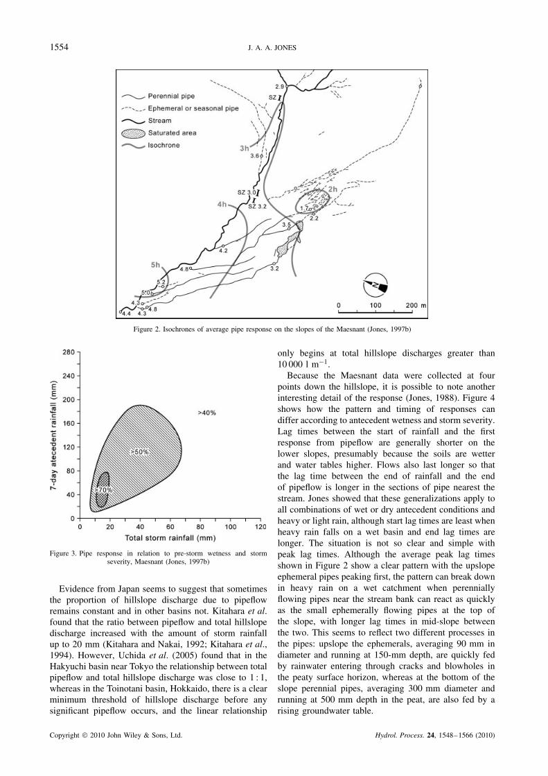
case with Weiler and McDonnell’s (2007) macroporeflow contributions. Indeed, there is some evidence that thepipes in Maesnant actually drive the timing of response.Figure 1 illustrates some of this variation. Figure 2 showsaverage isochrones of peak response relative to peakrainfall on the pipe slopes and in the stream, illustratingboth the timing and the spatial extension of stormflowcontributions.
The interplay between the wetness of the basin andthe amount and intensity of storm rainfall is crucial tothe timing and amount of pipe response. Figure 3 showsthis for the percentage of stream stormflow attributableto pipeflow in the Maesnant. Relative contributions arelow when the basin is dry and storm rainfall is low. Inthese situations, the ephemeral pipes may not respondat all, or else only after many hours delay. In fact, theephemeral pipes only react to about a quarter of theevents recorded in the perennial pipes which maintaincontinuous baseflow and are ‘ready primed’ to respond.Relative contributions peak when the basin is moderatelywet prior to the storm and the storm is of moderate size,and then they fall off when the basin is very wet beforethe storm and storm rainfall is high. Note, however, thatthis relates to percentage contributions. Contributions arehighest in absolute terms in the wettest conditions, butthe proportion of streamflow due to pipeflow falls off asother processes like overland flow and diffuse seepagefrom riparian bog areas begin to contribute significantdischarges.
Figure 2. Isochrones of average pipe response on the slopes of the Maesnant (Jones, 1997b)
Figure 3. Pipe response in relation to pre-storm wetness and stormseverity, Maesnant (Jones, 1997b)
Evidence from Japan seems to suggest that sometimesthe proportion of hillslope discharge due to pipeflowremains constant and in other basins not. Kitahara et al.found that the ratio between pipeflow and total hillslopedischarge increased with the amount of storm rainfallup to 20 mm (Kitahara and Nakai, 1992; Kitahara et al.,1994). However, Uchida et al. (2005) found that in theHakyuchi basin near Tokyo the relationship between totalpipeflow and total hillslope discharge was close to 1 : 1,whereas in the Toinotani basin, Hokkaido, there is a clearminimum threshold of hillslope discharge before anysignificant pipeflow occurs, and the linear relationship
only begins at total hillslope discharges greater than10 000 l m�1.
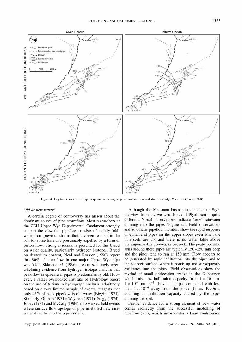
Because the Maesnant data were collected at fourpoints down the hillslope, it is possible to note anotherinteresting detail of the response (Jones, 1988). Figure 4shows how the pattern and timing of responses candiffer according to antecedent wetness and storm severity.Lag times between the start of rainfall and the firstresponse from pipeflow are generally shorter on thelower slopes, presumably because the soils are wetterand water tables higher. Flows also last longer so thatthe lag time between the end of rainfall and the endof pipeflow is longer in the sections of pipe nearest thestream. Jones showed that these generalizations apply toall combinations of wet or dry antecedent conditions andheavy or light rain, although start lag times are least whenheavy rain falls on a wet basin and end lag times arelonger. The situation is not so clear and simple withpeak lag times. Although the average peak lag timesshown in Figure 2 show a clear pattern with the upslopeephemeral pipes peaking first, the pattern can break downin heavy rain on a wet catchment when perenniallyflowing pipes near the stream bank can react as quicklyas the small ephemerally flowing pipes at the top ofthe slope, with longer lag times in mid-slope betweenthe two. This seems to reflect two different processes inthe pipes: upslope the ephemerals, averaging 90 mm indiameter and running at 150-mm depth, are quickly fedby rainwater entering through cracks and blowholes inthe peaty surface horizon, whereas at the bottom of theslope perennial pipes, averaging 300 mm diameter andrunning at 500 mm depth in the peat, are also fed by arising groundwater table.
Figure 4. Lag times for start of pipe response according to pre-storm wetness and storm severity, Maesnant (Jones, 1988)
Old or new water?
A certain degree of controversy has arisen about thedominant source of pipe stormflow. Most researchers atthe CEH Upper Wye Experimental Catchment stronglysupport the view that pipeflow consists of mainly ‘old’water from previous storms that has been resident in thesoil for some time and presumably expelled by a form ofpiston flow. Strong evidence is presented for this basedon water quality, particularly hydrogen isotopes. Basedon deuterium content, Neal and Rossier (1990) reportthat 80% of stormflow in one major Upper Wye pipewas ‘old’. Sklash et al. (1996) present seemingly over-whelming evidence from hydrogen isotope analysis thatpeak flow in ephemeral pipes is predominantly old. How-ever, a rather overlooked Institute of Hydrology reporton the use of tritium in hydrograph analysis, admittedlybased on a very limited sample of events, suggests thatonly 45% of peak pipeflow is old water (Biggin, 1971).Similarly, Gilman (1971); Weyman (1971); Stagg (1974);Jones (1981) and McCaig (1984) all observed field eventswhere surface flow upslope of pipe inlets fed new rain-water directly into the pipe system.
Although the Maesnant basin abuts the Upper Wye,the view from the western slopes of Plynlimon is quitedifferent. Visual observations indicate ‘new’ rainwaterdraining into the pipes (Figure 5a). Field observationsand automatic pipeflow monitors show the rapid responseof ephemeral pipes on the upper slopes even when thethin soils are dry and there is no water table abovethe impermeable greywacke bedrock. The peaty podsolicsoils around these pipes are typically 150–250 mm deepand the pipes tend to run at 150 mm. Flow appears tobe generated by rapid infiltration into the pipes and tothe bedrock surface, where it ponds up and subsequentlyexfiltrates into the pipes. Field observations show themyriad of small desiccation cracks in the O horizonwhich raise the infiltration capacity from 1 ð 10�3 to1 ð 10�4 mm s�1 above the pipes compared with lessthan 1 ð 10�6 away from the pipes (Jones, 1990): adoubling of infiltration capacity caused by the pipesdraining the soil.
Further evidence for a strong element of new watercomes indirectly from the successful modelling ofpipeflow (v.i.), which incorporates a large contribution
Figure 5. Exchanges between surface and subsurface flow in Maesnant:(a) overland flow draining into a pipe; (b) resurgence of pipeflowgenerating overland flow as pipe capacity is exceeded. Elsenbeer andVertessy (2000) also noted the frequent exchange between surface andsubsurface routes that complicate the analytical separation of sourcesin the La Cuenza basin, Amazonian rainforest, Peru. And Chappell andSherlock (2005) observed sink holes and resurgences along pipe routes onthe slopes of their research catchment at the Danum Valley Field Centre
in Borneo Island
from current rainfall (Jones and Connelly, 2002). It isalso clear from analysis of the numerous events moni-tored in Maesnant that pipe discharges and streamfloware proportionate to storm rainfalls with relatively lit-tle being stored within the basin. Further support comesfrom Elsenbeer et al. (1995), who concluded from chem-ical analyses that quickflow pathways, overland flow andpipeflow, in the Amazonian rainforest at La Cuenca, Peru,were dominated by new water.
More evidence is presented in Figure 6 which comesfrom Hyett’s (1990) study as part of the Welsh acidrain programme. This is taken from the largest peren-nial pipe in the system and shows the pattern of sodiumconcentration in pipeflow closely following the pattern ofsodium concentration in the current rainfall (Jones, 2004).Neal and Kirchner (2000) showed that sea-salt contam-inated rainfall is the predominant source of sodium onPlynlimon and very little is derived from weathering, soit is a good indicator of a rainfall source. They foundstrong correlations between sodium levels in rainwaterand groundwater on weekly or longer timescales, but the
time lag of hours in Hyett’s observations strongly sug-gests that the pipeflow is draining short residence timewater, either by direct supply to the pipes via macroporesor from shallow groundwater fed by rapid bypass flowthrough these macropores. The pattern in Figure 6 is wellpreserved until the latter stages, by which time, as Jones(2004) suggests, older groundwater might be issuing intothe pipe and diluting the rainfall signal. The dampening ofthe signal in the earlier stages may be partly explained byadsorption onto the soil cation exchange sites: Neal andKirchner (2000) found that sodium adsorption increasesas concentrations rise above the norm. Dampening mightalso be due to an element of older groundwater effluentfrom the start, but there is no significant decoupling oftimescales between rainfall and pipeflow.
Jones (1982) proposed the hypothesis that pipeflowis generated by a combination of vertical infiltrationthrough macropores into the pipe network and risingphreatic surfaces caused by vertical macropore flow inareas away from the pipes, which creates an hydraulicgradient in the direction of the pipes and hence effluentdrainage into the pipes. This hypothesis is generallyconfirmed by subsequent work at Maesnant and wasused as the basis for successful simulation modellingexperiments by Connelly (1993) and Jones and Connelly(2002). McDonnell (1990) came to the same conclusionindependently from research at Maimai.
An interesting feature was discovered by placingdipwells and piezometers in banks perpendicular to thelargest perennial pipe in Maesnant (Jones and Connelly,2002). This revealed a wave of groundwater mirroringthe progress of storm response in the pipe and migratingdownslope in sync with the peak discharge in the pipe.The wave occupies a slight trough in the surface andsubsurface topography along the length of the pipe. Theauthors conclude that this is evidence for groundwaterbeing fed by pipeflow—the reverse of the situationnormally envisaged. In fact, it could be seen as a variantof Gilman and Newson’s (1980) pipe leakage.
The throughput of acid rain also sheds light on thelikely processes. By diverting drainage through the Ohorizon and away from weathering mineral surfaces, theephemeral pipes reduce the buffering or acid neutralizingcapacity of the basin. Jones (1997b) reports average pHvalues of 4Ð84 in rainfall, 4Ð18 in ephemeral pipes, 4Ð92perennial pipes and 5Ð16 in the stream. The streamflow isclearly buffered by groundwater seepage from weatheringbedrock and this is also present in a more minor way inthe perennial pipes, which run on a mineral soil base andare fed by groundwater. Even so, pH in the perennialpipes falls during storms, e.g. averaging 4Ð27 in thelargest pipe. It also falls along the pipe as it starts off fedfrom a groundwater-fed mid-slope bog and then receivesextra discharge from peat-based tributaries and matrixflow (Jones, 1997b).
The solution to the dilemma must be that pipeflow canbe a variable mix of old and new water, and that this mixwill vary through the storm and from storm to storm, andfrom pipe to pipe, depending on antecedent conditions
Figure 6. Plot of sodium concentrations in rainfall and pipeflow (Hyett, 1990; Jones, 2004). Similarity of response indicates rapid drainage of newrainwater through the pipe
and storm rainfall intensity, amount and temporal pattern.Monitoring in relatively light storms and during the earlypart of pipeflow response is likely to display more oldwater, but the balance is likely to be reversed later in thestorm and with longer and heavier events. The fact thatHyett’s record comes from a perennial pipe where thecontribution from groundwater is expected to be strongerthan in the upslope ephemeral pipes adds further weightto the argument.
COMPARATIVE HYDROLOGY
The second important question is how the yield and tim-ing of pipeflow contributions compare with other hills-lope processes individually, even less research has beendevoted to this issue. Only two research programmes shedlight on it, one in the United Kingdom and the other inJapan. Jones (1997a) used data from Maesnant to plotpipeflow response on the graphs of peak lag time andpeak runoff rates for overland flow and throughflow ver-sus drainage basin area drawn by Anderson and Burt(1990). The original graphs were based on data collatedby Dunne (1978) and Kirkby (1985). In order to map
pipeflow response onto these graphs, Jones had to devisea method for estimating the drainage area feeding thepipes. He chose to use the common method for estimat-ing partial contributing areas in stream catchments, i.e.storm discharge divided by storm rainfall (Dickinson andWhiteley, 1970), omitting any rain falling after cessationof flow and selecting the worst storm on record.
The result shown in Figure 7, somewhat surprisingto the author, turned out to fit a very logical pattern.Pipeflow maps almost perfectly in between throughflowand saturation overland flow, with peak lag time increas-ing exponentially with ‘basin’ area and peak runoff ratesdecreasing. Data from 15 Maesnant pipes were used.
Uchida et al. (1999) provide a degree of corroborationfrom the Toinotani watershed in Ashiu near Kyoto.Although they only have results from two pipes, thesemap perfectly into the space between subsurface flow andsaturation flow in terms of peak lag times and are not faroff in terms of peak runoff rate. Their results have beenadded to those of Jones in Figure 7. Indirect evidence alsocomes from Kinner and Stallard (2004), who observedthat responses in the Lutz catchment in Panama plottednear the border of pipeflow and saturation overland flow
Figure 7. Generalized graph of hillslope process responses in relationto size of contributing area, showing position of ephemeral and peren-nial pipeflow (Jones, 1997b) with two additional pipeflow records fromUchida et al. (1999). Overland flow and throughflow/subsurface storm-flow data from Dunne (1978) and Kirkby (1985), as collated by Anderson
and Burt (1990) and Burt (1992)
in Figure 7, which they took to indicate the dominanceof these two processes in generating streamflow in thecatchment.
The conclusion to be drawn from this is that pipeflowis capable of approaching the performance of saturation
overland flow. The Maesnant evidence also suggeststhat the ephemeral pipes do not behave in a wayfundamentally different from perennial pipes in thisparticular regard: they are extensions of the same trends.They do, however, have smaller contributing areas andreact to fewer storms because they are shallower, furtherremoved from the water table and run through soils thatare generally drier at the start of rainfall.
But there are a number of factors that limit perfor-mance. One is whether the environment is conduciveto pipe development or not. The second is how exten-sive and interconnected the pipe networks are. The thirdis the size of the pipes. The ephemeral pipes in Maes-nant are barely one third of the diameter of the perennialpipes, and all pipes are limited by there cross-sectionalarea compared with saturation overland flow. The sys-tem partially overcomes this limit by overflowing throughsurface blowholes, or by even small artesian fountains,releasing overland flow, which may or may not return tothe pipe system lower downslope. There are also somepipes that are purely overflow pipes, only operating whenthe main pipe is near capacity. These are distributarypipes, like channels in a river delta. It may be that some ofthe clusters of ephemeral pipes found by Jones (1971) inthe banks of the Burbage Brook are formed by concealedpipe deltas. In Malaysia, Sayer et al. (2006) observedpipe capacities of 2Ð8 l s�1 rising to 4Ð3 l s�1 in stormsof high intensity and magnitude as connectivity improvedwithin the system.
The Maesnant programmes also measured contribu-tions from riparian seepage zones, some of them fed bypipes, others not (Figure 8). Figure 9 shows a comparisonof the yield efficiency of these seeps with the ephemeral
Figure 8. Monitored pathways of hillslope drainage in the Maesnant Experimental Catchment during an average storm of 30 mm (Jones, 1990)
Figure 9. Relative efficiency of drainage response from pipes and seepsin Maesnant, measured by yield per square metre of contributing area
and contributions per metre length of streambank (Jones, 1997a)
and perennial pipes, determined by the yield per squaremetre of the drainage area contributing to them (Jones,1997a). It shows the relative efficiency of the pipes.
One major deficiency to date has been the lack oflike-for-like comparative studies on pipeflow effects indifferent environments. As Table I shows, the collatedevidence ranges from a handful of manual samples ofpipeflow taken over a few weeks to one case of 9 yearsof continuous measurements at up to 17 pipeflow sites.Many site descriptions also present limited environmen-tal information and different soil classifications. Uchidaet al. (2005) were the first to undertake a comparativehydrology of a number of piped catchments in a reason-ably uniform approach, taking basins in Georgia, USA,and three Japanese basins near Kyoto and Tokyo in Hon-shu and one in Hokkaido. They discovered a numberof features common to all the sites: the relationshipsbetween rainfall and pipeflow amounts were highly non-linear and exhibited thresholds, the threshold for pipeflowinitiation varied with pre-storm and storm rainfall, peakpipeflow discharge was sensitive to peak rainfall inten-sity, and the ratio of total pipeflow to total hillslopedischarge was constant.
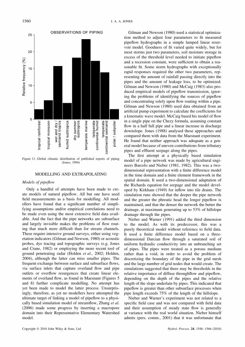
OCCURRENCE AND DISTRIBUTION OF SOILPIPING
Despite this evidence, pipeflow would remain little morethan a curiosity if soil piping is a rare occurrence. Studieson the distribution of natural piping show that it is limitedto certain environments, but that it is also widespread inthose which are favourable.
The survey by Jones et al. (1997) showed that it iswidespread in the British uplands (Figure 10). Its relativeabsence in the lowlands may be explained partly by
Figure 10. Map of 70 basins in Britain with known piping, relative tohydrological classification of soils. Most are in the uplands and onsoils with low permeability (low Winter Rainfall Acceptance Potential)traditionally seen as favouring overland flow (Jones, 1997b; Jones
et al., 1997)
agricultural interference, but it is principally explainedby lack of suitable soils and the erosive potential createdby steeper slopes and hydraulic gradients. The needfor cracking (high expansion index) or dispersive soils,sufficient hydraulic conductivity to permit turbulent flowsand underlying horizons with low permeability are welldocumented (Jones, 1981). The one sighting of pipingin the East Anglian lowlands on the Bourne Brook nearCambridge owes its existence to local highly expansiveclay soils.
In global terms, reports of piping span almost everyclimatic zone (Figure 11). A considerable amount ofresearch has been conducted on piping processes, e.g. inAustralia, New Zealand and Spain, including a detailedmonograph on piping in South Africa (Beckedahl, 1998),but most of this has been more concerned with geomor-phological processes than with hydrological processes(cp. Jones and Bryan, 1997; Jones, 1981). Jones (1981)gives a full exploration of the environmental factors con-ducive to piping development and this has been thor-oughly updated by Faulkner (2006) exploring the risk ofpipe erosion in the EU.
Figure 11. Global climatic distribution of published reports of piping(Jones, 1994)
MODELLING AND EXTRAPOLATING
Models of pipeflow
Only a handful of attempts have been made to cre-ate models of natural pipeflow. All but one have usedfield measurements as a basis for modelling. All mod-ellers have found that a significant number of simpli-fying assumptions and/or empirical correlations need tobe made even using the most extensive field data avail-able. And the fact that the pipe networks are subsurfaceand largely invisible makes the problems of flow rout-ing that much more difficult than for stream channels.These require intensive ground surveys, either using veg-etation indicators (Gilman and Newson, 1980) or acousticprobes, dye tracing and topographic surveys (e.g. Jonesand Crane, 1982) or employing the more recent tool ofground penetrating radar (Holden et al., 2002; Holden,2004), although the latter can miss smaller pipes. Thefrequent exchange between surface and subsurface flows,via surface inlets that capture overland flow and pipeoutlets or overflow resurgences that create linear ele-ments of overland flow, as found in Maesnant (Figures 5and 8) further complicate modelling. No attempt hasyet been made to model the latter process. Unsurpris-ingly, therefore, as yet no modellers have attempted theultimate target of linking a model of pipeflow to a physi-cally based simulation model of streamflow, Zhang et al.(2006) made some progress by inserting a macroporedomain into their Representative Elementary Watershedmodel.
Gilman and Newson (1980) used a statistical optimiza-tion method to adjust four parameters to fit measuredpipeflow hydrographs in a simple lumped linear reser-voir model. Goodness of fit varied quite widely, but formost storms just two parameters, soil moisture storage inexcess of the threshold level needed to initiate pipeflowand a recession constant, were sufficient to obtain a rea-sonable fit. Some storm hydrographs with exceptionallyrapid responses required the other two parameters, rep-resenting the amount of rainfall passing directly into thepipes and the amount of leakage loss, to be optimized.Gilman and Newson (1980) and McCaig (1983) also pro-duced empirical models of pipeflow transmission, ignor-ing the problems of identifying the sources of pipeflowand concentrating solely upon flow routing within a pipe.Gilman and Newson (1980) used data obtained from anartificial pump experiment to calculate the coefficients fora kinematic wave model. McCaig based his model of flowin a single pipe on the Chezy formula, assuming constantflow in a half full pipe and a linear increase in dischargedownslope. Jones (1988) analysed these approaches andcompared them with data from the Maesnant experiment.He found that neither approach was adequate as a gen-eral model because of uneven contributions from tributarypipes and effluent seepage along the pipes.
The first attempt at a physically based simulationmodel of a pipe network was made by agricultural engi-neers Barcelo and Nieber (1981, 1982). This was a two-dimensional representation with a finite difference modelin the time domain and a finite element framework in thespatial domain. It used a two-dimensional adaptation ofthe Richards equation for seepage and the model devel-oped by Kirkham (1949) for inflow into tile drains. Thesimulation runs showed that the deeper the pipe networkand the greater the phreatic head the longer pipeflow ismaintained, and that the denser the network the better thedrainage, at maximum generating up to 53% of hillslopedrainage through the pipes.
Nieber and Warner (1991) added the third dimensionto the model. As with its predecessor, this was apurely theoretical model without reference to field data.It used a finite difference model based on a three-dimensional Darcian flow through a saturated soil ofuniform hydraulic conductivity into an unbranching setof pipes. The pipes were treated as a porous mediumrather than a void, in order to avoid the problem ofdiscretizing the boundary of the pipe in the grid meshand the large number of grid nodes that would create. Thesimulations suggested that there may be thresholds in therelative importance of diffuse throughflow and pipeflow,depending on the depth of the pipes and the relativelength of the slope underlain by pipes. This indicated thatpipeflow is greater than other subsurface processes whenpipe length exceeds 75% of the length of the hillslope.
Nieber and Warner’s experiment was not related to aspecific field case and was not compared with field dataand their assumption of steady state flow is generallyat variance with the real world situation. Nieber himselfadmits (pers. comm., 2001) that it was unfortunate that
Figure 12. Comparison of the results of Nieber and Warner’s (1991)pipeflow simulation model with the field data on overland flow andthroughflow used in Figure 7, together with the Maesnant pipeflow data.The points marked by ‘x’ are plotted from calculations based on Nieberand Warner’s Table I. ‘O’ indicates overland flow, ‘T’ throughflow and
‘P’ pipeflow
the simplifying assumptions of the model meant thatcontinuous saturation overland flow had to be maintainedthroughout each simulation. As a result, Nieber andWarner’s (1991) Table I clearly shows that only 3% ofrainfall actually drained by subsurface routes and 94%ran off as overland flow, although the authors did notcomment on this.
Figure 12 compares the results of Nieber and Warner’scomputer simulations with data collated from a widevariety of field experiments and presented by Dunne(1978), Kirkby (1985), Anderson and Burt (1990) andBurt (1992) on overland flow and throughflow and byJones (1997a, b, c) on pipeflow. Interpolating from thesedata for a catchment area of 0Ð001 km2 indicates typi-cal runoff coefficients of only 35% for Hortonian over-land flow, 10% for throughflow and 56% for pipeflow(Jones, 1997b), compared with the largest catchment inNieber and Warner’s simulations with a comparable areaof 0Ð0012 km2 in which the figures are, respectively, 94,1Ð2 and 1Ð6%. Admittedly, the pipeflow data are derivedsolely from one catchment and the runoff coefficient forsaturation overland flow may be somewhat higher thanfor infiltration excess overland flow. However, the dis-crepancies between the model results and the best fielddata available are very marked. The discrepancies areeven greater when Nieber and Warner’s results are com-pared with field data from the Maesnant ExperimentalCatchment shown in the flow chart of Figure 8. For anaverage storm in this basin, the overall runoff coeffi-cient is 68%, which is divided between pipeflow (44%),throughflow seepage (21%) and saturation overland flow(3%).
Jones and Connelly (2002) present the most physicallybased simulation model to date, based on the extensivedatabase from Maesnant. This is admittedly site specificand relates solely to the main pipe system in the basin,which is 750-m long and comprises ephemeral pipesin the upslope area and a mid-slope bog that suppliescontinuous baseflow to the perennial pipe on the lowerslope (Figure 4). It includes two sources of pipeflow:(1) a headwater feeding zone and (2) lateral and verti-cal inflows along the length of the pipe. Overland flowentering through cracks or pipeheads is supplementedby saturated throughflow effluent. The model is semi-distributed as the pipe system is broken down into dis-crete sections of varying length that each have their owndistinct geometric properties, which are assumed to beuniform within that segment. This includes depth, slope,diameter and cross-sectional shape, each modelled to fitthe actual system in the basin. The model was run for anumber of storm events recorded in the field, includingantecedent and storm rainfall, and the results comparedwith reality. The results were encouraging, with the �2
goodness of fit test showing no significant differencebetween observed and predicted discharges. Neverthe-less, calibration was needed and some parameters wereadjusted empirically to improve the fit, especially thoserelating to the lateral hydraulic gradient perpendicularto the pipe, the rate of lateral seepage into the pipeand the recession constant, which are highly dependenton antecedent moisture levels. To do this, the recordedevents were split into 5 calibrating storms and 15 simu-lated storms.
The laborious task of deriving the geometric parame-ters of the network and the difficulties in monitoring orestimating soil moisture levels around the pipes illustratethe severe problems inherent in this approach and thedifficulties of using it to extrapolate to ungauged basins.
Extrapolating results
Given the difficulties of developing transportableprocess-based models, is it possible to use generalizationsbased on the limited data available?
Jones (1997c) explored the prospects for predicting theintensity of piping landforms and of piping processesbased on data presented in published surveys. Theintensity of piping is a more meaningful measure thanpipe frequency, and is defined as the total area of pipecross-sections per kilometre of distance along a transectperpendicular to the slope across the lower side slopesor along the streambank, in square metres per kilometre.Only some of the British surveys provide enough mapinformation to work with, a total of just nine basins forthe landforms. These suggested power law relationshipsbetween pipe intensity and side slope gradient, meanannual rainfall and mean annual water surplus, but onlythe first of these correlations was significant at the 5%level. Interestingly, despite the evidence presented byHolden and Burt (2002) suggesting that the hydrologicalrole of piping may be different in deep peats, when Jones
Figure 13. Relationship between average hillslope gradient and intensityof piping based on ten British catchments (Jones, 2004)
Figure 14. Pipeflow runoff coefficients and contributing areas in Maes-nant (Jones, 1997c)
(2004) added piping intensity measurements from theirLittle Dodgen Pot Sike catchment to the intensity/slopegraph, it did not plot so far out of line with the other ninecatchments (Figure 13). It actually adds to the number oflow gradient/low intensity cases, making a total of three:still very few and really diagnosing any trend at all isvery dependent on those three cases.
The graphs in Figure 7 could offer some basis forextrapolating pipe response, but only provided the sizeof the pipeflow contributing areas can be estimated,perhaps by remote sensing. Jones (2004) found a weakrelationship between pipeflow runoff coefficients andcatchment area, based on the 15 pipe sites in Maesnant(Figure 14).
CONCLUDING REMARKS
The available evidence suggests that pipeflow can be ahighly significant contributor to storm runoff in catch-ments. Only certain environments are conducive to pipedevelopment, depending on soil type, relief, land use,rainfall and water balance. However, it is not as rareas once supposed. Reports of piping are widespreadthroughout the world. Most of these reports have beenconcerned with pipe erosion rather than pipe hydrology,but where the hydrology has been studied, the pipes gen-erally prove to have a significant role. Studies on pipehydrology in the field in the United States are quite lim-ited, despite the modelling efforts of Nieber et al., theconcern for piping in river banks expressed by Hagertyet al. (e.g. Hagerty, 1991a, b) and studies on widespreadpiping in the arid zone (e.g. Masannat, 1980). EvenMcDonnell’s excellent new online virtual short coursestill refers to the main contribution of stormwater comingfrom the near-stream saturated zone and delayed con-tributions coming from higher upslope only during therecession (McDonnell, online). The large and extensivepipe networks which are the main focus of this reviewalter this model substantially, especially by extending thepeak stormflow contributing areas of streams much fur-ther uphill.
This has important implications for the management ofpiped basins, particularly as regards afforestation (Jones,2004; Jones and Cottrell, 2007), as well as for correctprocess modelling of storm runoff. It also affects waterquality. Neal et al. (1997) concluded that classifyingthe vulnerability of catchments to acid rain purely onthe basis of soil type is inadequate and that drainagepathways also need to be considered. However, thefindings of Hyett (1990), Chapman et al. (1997) andNeal (2000) indicate that pipeflow chemistry is extremelycomplex. The wide temporal and spatial variation in thechemical properties of water from pipes and other sourcesmeans that the popular end member mixing analysis(EMMA) approach to identify the relative contributionsfrom different pathways can be very misleading (Jones,2004).
Some indication of the extent of the distribution ofpiping in Europe is given by Faulkner (2006), whoestimates that 260 000 km2 within the European Union isat risk from serious pipe erosion. Loess-derived soils areespecially vulnerable (Verachtert et al., in press). Jones(2004) estimated that 30% of the land area of Britain (notthe ‘United Kingdom’ as an editor added) is covered bysoils that are susceptible to pipe development. It occursfrequently in the British uplands, especially in catchmentswhere the soils’ Winter Rainfall Acceptance Potential, ameasure developed for the original UK Flood StudiesReport (NERC, 1975), indicates soils prone to overlandflow. In reality, overland flow is rarely observed there, butsubsurface pipeflow performs a similar function. Thus,runoff coefficients may be correctly predicted but for thewrong reasons.
In effect, pipes extend the stream network, just likeoverland flow in swales as observed by Gregory and
Figure 15. Changes in the intensity of piping in the banks of the BurbageBrook, Derbyshire, over a 35-year period. There is a significant reductionon the eastern bank that was afforested after the first survey and no changeon the moorland bank. Measured in square metres of pipe outlet perkilometre length of bank, based on data presented by Jones and Cottrell
(2007)
Walling (1968) or Hewlett’s (1974) proposition of returnflow feeding linear saturation overland flow. Jones(1987b) observed that accounting for the pipe networkin Maesnant improved the fit of Kirkby’s (1978) formulafor predicting stream density from annual rainfall. With-out accounting for the pipes, the stream density was wellbelow than the predicted. Kirkby’s formula predicted adensity of 5Ð6 km km�2 against the actual 2 km km�2,but this was raised to 3Ð1 km km�2 when allowance wasmade for the role of the pipes (Jones, 1990).
A recent resurvey of the Burbage Brook catchment,which was intended to investigate the hypothesis thatpipes can form the focus for channel extension 35 yearsafter the original (Jones, 1971, 1987b, 1990, 1997b),found something quite different (Figure 15). The inten-sity of piping had been reduced on the side of thecatchment where afforestation had taken place (Jones andCottrell, 2007). It underlines the sensitivity of piping toland use and offers another perspective on Frank Law’s(1956) proposition that forests reduce water resources,which was the hypothesis that the Institute of Hydrologywas found to test.
Holden (2006) and Holden et al. (2006) found evi-dence of different land management having the oppositeeffect. Comparing two peatland catchments which hadundergone land drainage with two that had not, showedthat pipes and macropores were more important sourcesof runoff in the artificially drained catchments. Holden(2006) estimated that the rate of pipe erosion increasedexponentially over time and predicted that it would dou-ble in 35 years. This seems to be a case where increasedhydraulic gradients caused by the ditching have stimu-lated piping erosion (cp. Jones, 1981).
Unfortunately, overall there are still too few detailedstudies and an almost total lack of comparative studiescomparing pipeflow regimes in different environmentswith similar methodology, and, indeed, using the samedefinition of a pipe. It is still difficult to extrapolateresults to ungauged basins or to create transportablemodels. The heterogeneity in pipe response in a singlebasin, as reported by Jones (1987b), is even greater when
different climates and different soils are involved. AsMcDonnell et al. (2007) state, there is a need to ‘explorethe set of organizing principles that might underlie theheterogeneity and complexity’. But the target is currentlysome way off.
This review has been concerned with the physicalresponse of pipeflow, but there are also important con-siderations regarding the role of pipeflow in water qual-ity, especially its role in increasing the acidification ofstreamwater, which has been analysed in detail elsewhere(e.g. Hyett, 1990; Jones, 1994, 1997b, 2004).
ACKNOWLEDGEMENTS
I wish to thank a number of colleagues who havecontributed comments and offprints for this review,especially Joseph Holden, Rory Walsh, Colin Neal, Ming-ko Woo, T. X. Zhu, T. Uchida, Jean Poesen, BrianReynolds, John Nieber and M. R. Y. Putty.
REFERENCES
Albright JS. 1991. Storm hydrograph comparisons of subsurface in asmall, forested watershed in northern California, Unpub. MSc thesis,Humboldt State University, Arcata, California, USA.
Anderson MG, Burt TP. 1990. Subsurface runoff. In Process Studies inHillslope Hydrology , Anderson MG, Burt TP (eds). Wiley: Chichester;365–400.
Aubertin GM. 1971. Nature and extent of macropores in forest soils andtheir influence on subsurface water movement , U.S. Department ofAgriculture, Forest Service, Northeastern Forest Experiment Station,Research Paper NE-192. Upper Darby, PA, 33.
Barcelo MD, Nieber JL. 1981. Simulation of the hydrology of naturalpipes in a soil profile, American Society of Agricultural Engineers:paper number 82–2026, St Joseph, MI, 23.
Barcelo MD, Nieber JL. 1982. Influence of a soil pipe network oncatchment hydrology , American Society of Agricultural Engineers:paper number 82–2027, St Joseph, MI, 27.
Beckedahl HR. 1998. Subsurface soil erosion phenomena in South Africa,Petermanns Geographische Mitteilungen Erganzungsheft 290, JustusPerthes Verlag: Gotha, 128.
Betson RP. 1964. What is watershed runoff?. Journal of GeophysicalResearch 69: 1541–1552.
Beven KJ, Germann P. 1982. Macropores and water flow in soils. WaterResources Research 18(5): 1311–1325.
Beven K, Kirkby MJ. 1979. A physically-based, variable contributingarea model of basin hydrology. Hydrological Sciences Bulletin 24:43–69.
Bidin K. 1995. Subsurface flow controls of runoff in a Bornean naturalrainforest , Unpub. MSc thesis, University of Manchester, UK.
Biggin DS. 1971. The use of tritium in hydrograph analysis , SubsurfaceHydrology Report No. 26, NERC Institute of Hydrology, Wallingford,16.
Bosch DD, King KW (eds). 2001. Preferential Flow: Water Movementand Chemical Transport in the Environment , American Society ofAgricultural and Biological Engineers: St. Joseph, MI; 328.
Bryan RB, Harvey LE. 1985. Observations on the geomorphicsignificance of tunnel erosionin a semiarid ephemeral drainage system.Geographiska Annaler, series A 67: 257–273.
Bryan RB, Jones JAA. 1997. The significance of soil piping processes:inventory and prospect. Geomorphology 20(3–4): 209–218.
Burt TP. 1992. The hydrology of headwater catchments. In The RiverHandbook , vol. 1. Calow P, Petts GE (eds). Oxford: Blackwell; 3–28.
Burt TP, Heathwaite AL, Labadz JC. 1990. Runoff production in peat-covered catchment. In Process Studies in Hillslope Hydrology .Anderson MG, Burt’ TP (eds). Wiley: Chichester; 463–500.
Carey SK, Woo M-K. 2000. The role of soil pipes as a slope runoffmechanism, Subarctic Yukon, Canada. Journal of Hydrology 233:206–222.
Carey SK, Woo M-K. 2002. Hydrogeomorphic relations among soilpipes, flow pathways, and soil detachments within a permafrosthillslope. Physical Geography 23: 95–114.
Carson MA, Kirkby MJ. 1972. Hillslope Form and Process . CambridgeUniversity Press: Cambridge; 475.
Chapman PJ. 1994. Hydrochemical processes influencing episodic streamwater chemistry in a small headwater catchment, Plynlimon, mid-Wales , Unpub. PhD thesis, University of London, UK, 416.
Chapman PJ, Reynolds B, Wheater HS. 1993. Hydrochemical changealong stormwater pathways in a small moorland headwater catchmentin mid-Wales, UK. Journal of Hydrology 151: 241–265.
Chapman PJ, Reynolds B, Wheater HS. 1997. Sources and controls ofcalcium and magnesium in storm runoff: the role of groundwater andion exchange reactions along water pathways. Hydrology and EarthSystem Sciences 1: 671–685.
Chappell NA, Sherlock MD. 2005. Contrasting flow pathways withintropical forest slopes of ultisol soils. Earth Surface Processes andLandforms 30: 735–753.
Connelly LJ. 1993. Modelling stormflow in natural subsurface pipes ,Unpub. PhD thesis, University of Wales, Aberystwyth; 419.
Dickinson WT, Whiteley H. 1970. Watershed areas contributing torunoff , in International Association of Scientific Hydrology Pub. No96, 12–26.
Dunne T. 1978. Field studies of hillslope processes. In HillslopeHydrology , Kirkby MJ (ed.). Wiley: Chichester; 227–294.
Elsenbeer H, Lack A, Cassel K. 1995. Chemical fingerprints of hydro-logical compartments and pathway characteristics in an Amazonianrainforest catchment. Hydrological Processes 14: 2367–2381.
Elsenbeer H, Vertessy RA. 2000. Stormflow generation and flowpathcharacteristics in an Amazonian rainforest catchment. HydrologicalProcesses 14: 2367–2381.
Faulkner H. 2006. Piping hazard in collapsible and dispersible soils inEurope. In Soil Erosion in Europe, Boardman J, Poesen J (eds). Wiley:London; 537–562.
Gardiner AT. 1983. Runoff and erosional processes in a peat-moorlandcatchment , Unpub. MPhil. thesis, Huddersfield Polytechnic.
Garland G, Humphrey B. 1992. Field-measurements of discharge andsediment yield from a soil pipe in the Natal Drakensberg, South Africa.Zeitschrift fur Geomorphologie 36(1): 15–23.
Gilman K. 1971. A semi-quantitative study of the flow of natural pipesin the Nant Gerig sub-catchment , NERC Institute of Hydrology,Subsurface Section, internal report No. 50, Wallingford, 7.
Gilman K, Newson MD. 1980. Soil Pipes and Pipeflow—A HydrologicalStudy in Upland Wales . Geobooks: Norwich; 114.
Gregory KJ, Walling DE. 1968. The variation of drainage densitywithin a catchment. Bulletin of International Association of ScientificHydrology 13(2): 61–68.
Hewlett JD. 1961. Soil moisture as a source of base flow from steepmountain watersheds , US Department of Agriculture Forest Service,Southeastern Forest Experimental Station, Asheville, North Carolina,Station Paper No. 132: 11.
Hewlett JD. 1974. Comments on letters relating to “Role of subsurfaceflow in generating surface runoff. 2, Upland source areas” by R.A.Freeze. Water Resources Research 10(3): 605–607.
Hewlett JD, Hibbert AR. 1967. Factors affecting the response of smallwatersheds to precipitation in humid areas. Proceedings of theInternational Symposium on Forest Hydrology (1965). PennsylvaniaState University: Pergamon; 275–290.
Holden J. 2004. Hydrological connectivity of soil pipes determinesd byground penetrating radar tracer detection. Earth Surface Processes andLandforms 29(4): 437–442.
Holden J. 2005. Controls on soil pipe frequency in upland blanketpeat. Journal of Geophysical Research 110(F1): F02010, DOI:10.1029/2005/JF000386.
Holden J. 2006. Sediment and particulate carbon removal by pipe erosionincrease over time in blanket peats as a consequence of land drainage.Journal of Geophysical Research (Earth Surface) 111(F2): F02010.
Holden J. 2009. Flow through macropores of different size classes inblanket peat. Journal of Hydrology 364: 342–348.
Holden J, Burt TP, Vilas M. 2002. Application of ground-penetratingradar to the identification of subsurface piping in blanket peat. EarthSurface Processes and Landforms 27: 235–249.
Holden J, Burt TP. 2002. Piping and pipeflow in a deep peat catchment.Catena 48: 163–199.
Holden J, Evans MG, Burt TP, Horton M. 2006. Impact of landdrainage on peatland hydrology. Journal of Environmental Quality 35:1764–1778.
Holden J, Smart RP, Chapman PJ, Baird AJ, Billett MF. 2009. The roleof natural soil pipes in water and carbon transfer in and from peatlands.Geophysical Monograph Series 184: 1–15.
Hyett GA. 1990. The effect of accelerated throughflow on the water yieldchemistry under polluted rainfall , Unpub. PhD thesis, University ofWales, Aberystwyth, UK.
Ingles OG. 1968. Soil chemistry relevant to the engineering behaviour ofsoils. In Soil Mechanics—Selected Topics , Lee IK (ed.). Butterworth:London.
Jones JAA, Richardson JM, Jacobs HJ. 1997. Factors controlling thedistribution of piping in Britain: a reconnaissance. Geomorphology20(3–4): 289–306.
Jones JAA. 1971. Soil piping and stream channel initiation. WaterResources Research 7(3): 602–610; Reprinted with commentaryin Streamflow Generation Processes . Beven KJ (ed.) BenchmarkPapers in Hydrology Series No. 1, 2006 International Association ofHydrological Sciences Pub.: Wallingford, 224–232.
Jones JAA. 1975. Soil piping and the subsurface initiation of streamchannel networks , Unpub. PhD thesis, University of Cambridge,Cambridge, UK, 467.
Jones JAA. 1978. Soil pipe networks: distribution and discharge.Cambria 5(1): 1–21.
Jones JAA. 1979. Extending the Hewlett model of stream runoffgeneration. Area 11(2): 110–114.
Jones JAA. 1981. The Nature of Soil Piping: A Review of Research .British Geomorphological Research Group Research Monograph 3.GeoBooks: Norwich; 301.
Jones JAA. 1982. Experimental studies of pipe hydrology. In BadlandsGeomorphology and Piping , Bryan RB, Yair A (eds). GeoBooks:Norwich; 355–370.
Jones JAA. 1986. Some limitations to the a/s index for predicting basin-wide patterns of soil water drainage. Zeitschrift fur Geomorphologie60: (Supplement): 7–20. Supplementband 60.
Jones JAA. 1987a. The initiation of natural drainage networks. Progressin Physical Geography 11(2): 207–245.
Jones JAA. 1987b. The effects of soil piping on contributing areasand erosion patterns. Earth Surface Processes and Landforms 12(3):229–248.
Jones JAA. 1988. Modelling pipeflow contributions to stream runoff.Hydrological Processes 2: 1–17.
Jones JAA. 1990. Piping effects in humid lands. In GroundwaterGeomorphology: The Role of Subsurface Water in Earth-surfaceProcesses and Landforms , Higgins CG, Coates DR (eds). GeologicalSociety of America: Boulder, Colorado, Special Paper 252, 111–138.
Jones JAA. 1994. Soil piping and its hydrogeomorphic function.Cuaternario y Geomorfologıa 8(3–4): 77–102.
Jones JAA. 1997a. Pipeflow contributing areas and runoff response.Hydrological Processes 11(1): 35–41.
Jones JAA. 1997b. Subsurface flow and subsurface erosion: furtherevidence on forms and controls. In Process and Form inGeomorphology , Stoddart DR (ed.). Routledge: London; 74–120.
Jones JAA. 1997c. The role of natural pipeflow in dynamic contributingareas and hillslope erosion: extrapolating from the Maesnant data.Physics and Chemistry of the Earth 22(3–4): 303–308.
Jones JAA. 1997d. Maesnant, Pumlumon (Plynlimon), Wales’, sectionin Lewin, J. Fluvial landforms and processes in Wales, Chapter 3of Gregory KJ (ed.) Fluvial Geomorphology of Great Britain, JointNature Conservation Committee, Geological Conservation ReviewSeries, Chapman and Hall: London; 164–167.
Jones JAA. 2004. Implications of natural soil piping for basinmanagement in the British uplands. Land Degradation & Development15(3): 325–349. DOI: 10.1002/ldr.618.
Jones JAA, Connelly LJ. 2002. A semi-distributed simulation modelfor natural pipeflow. Journal of Hydrology 262(1–4): 28–49. DOI:10.1029/2006/JF000509.
Jones JAA, Cottrell CI. 2007. Long-term changes in streambank soilpipes and the effects of afforestation’. Journal of Geophysical Research112(F1): F01010-1–F01010-11.
Jones JAA, Crane FG. 1982. New evidence for rapid interflowcontributions to the streamflow hydrograph. Beitrage zur HydrologieSonderheft 3: 219–232.
Jones JAA, Crane FG. 1984. Pipeflow and pipe erosion in theMaesnant experimental catchment. In Catchment Experiments in
Fluvial Geomorphology , Burt TP, Walling DE (eds). GeoBooks:Norwich; 55–72.
Jones JAA, Wathern P, Connelly LJ, Richardson JM. 1991. Modellingflow in natural soil pipes and its impact on plant ecology in mountainwetlands. In Hydrological Basis of Ecologically Sound Managementof Soil and Groundwater , vol. 202, Nachtnebel P (ed.). InternationalAssociation of Hydrological Sciences Publication; 131–142.
Kinner DA, Stallard RF. 2004. Identifying storm flow pathways in arainforest catchment using hydrologic and geochemical modelling.Journal of Hydrology 308: 67–80. DOI: 10.1016/j.hydrol.2004.10.022.
Kirkby MJ. 1978. Implications for sediment transport. In HillslopeHydrology , Kirkby MJ (ed.). London: Wiley; 325–363.
Kirkby MJ. 1985. Hillslope hydrology. In Hydrological Forecasting ,Anderson MG, Burt TP (eds). Wiley: Chichester; 37–75.
Kirkby MJ, Chorley RJ. 1967. Throughflow, overland flow and erosion.Bulletin of the International Association of Scientific Hydrology 12(3):5–21.
Kirkham D. 1949. Flow of ponded water into drain tubes in soil overlyingan impervious layer. Transactions of American Geophysical Union 30:369–385.
Kitahara H. 1989. Characteristics of pipe flow in a subsurface soil layeron a gentle slope (II) Hydraulic properties of pipes. Journal of theJapanese Forestry Society 70: 317–322.
Kitahara H. 1994. A study on the characteristics of soil pipes influencingwater movement in forested slopes. Bulletin of the Forestry and ForestProducts Research Institute 367: 63–115.
Kitahara H, Nakai Y. 1992. Relationship of pipe flow in to streamflowon a first order watershed. Journal of the Japanese Forestry Society74: 49–52.
Kitahara H, Terajima T, Nakai Y. 1994. Ratio of pipe flow to throughflow. Journal of the Japanese Forestry Society 76: 10–17.
Knapp BJ. 1970. Patterns of water movement on a steep upland hillside,Plynlimon, Central Wales , Unpub. PhD thesis, University of Reading,UK, 213.
Koyama K, Okumura T. 2002. Process of pipeflow runoff with twiceincrease in discharge for a rainstorm. Transactions of the JapaneseGeomorphological Union 23: 561–584.
Law F. 1956. The effect of afforestation upon the yield of watercatchment areas. Journal of the British Waterworks Association 38:489–94.
Masannat YM. 1980. Development of piping erosion conditions in theBenson area, Arizona, USA. Quarterly Journal of Engineering Geology13: 53–61.
McCaig M. 1983. Contributions to storm quickflow in a small headwatercatchment: the role of natural pipes and soil macropores. Earth SurfaceProcesses and Landforms 8: 239–252.
McCaig M. 1984. Patterns of wash erosion around an uplandstreamhead. In Catchment experiments in fluvial geomorphology .Burt TP, Walling DE (eds), GeoBooks: Norwich; 87–114.
McDonnell JJ. 1990. A rationale for old water discharge throughmacropores in a steep, humid catchment. Water Resources Research26: 2821–2832.
McDonnell JJ undated: New virtual short course online. At www.cof.orst.edu/cof/fe/watershd/. Accessed November 10th, 2009.
McDonnell JJ, Sivapalan M, Vache K, Dunn S, Grant G, Hagerty R,Hinz C, Hooper R, Kirchner J, Roderick ML, Selker J, Weiler M.2007. Moving beyond heterogeneity and process complexity: anew vision for watershed hydrology. Water Resources Research 43:W07301. DOI:10.1029/2006WR005467.
McGuire KJ, McDonnell J, Weiler M, Kendall C, Welker J, McGlynn B,Seibert J. 2005. The role of topography on catchment-scalewater residence time. Water Resources Research 41: W05002.DOI:10.1029/2004WR003657.
Mosely MP. 1979. Streamflow generation in a forested watershed, NewZealand’. Water Resources Research 15: 795–806.
Mizuyama T, Sato I, Kosugi K. 1994. Pipe flow and pipe distribution atTohinotani basin in Ashu experimental forest. Bull. Kyoto UniversityForest . 66: 48–60 (Japanese with English summary).
Natural Environment Research Council (NERC). 1975. Flood studiesreport , 5 volumes, Natural Environment Research Council: London.
Neal C. 2000. Catchment science in a heterogeneous world: reflections onthe water quality functioning of the Plynlimon catchments, mid-Wales.In Water in the Celtic World: Managing Resources for the 21st century ,Jones JAA, Gilman K, Jigorel A, Griffin J (eds), British HydrologicalSociety Occasional Paper No. 11, 189–196.
Neal C, Rosier PTW. 1990. Chemical studies of chloride and stableoxygen isotopes in two conifer afforested and woodland sites in theBritish uplands. Journal of Hydrology 15: 269–283.
Neal C, Hill T, Hill S, Reynolds B. 1997. Acid neutralization capacitymeasurements in surface and ground waters in the upper Severn,Plynlimon: from hydrograph splitting to water flow pathways.Hydrology and Earth Systems Science 1: 687–696.
Neal C, Kirchner JW. 2000. Sodium and chloride levels in rainfall,mist, streamwater and groundwater at the Plynlimon catchments, mid-Wales—inferences on hydrological and chemical controls. Hydrologyand Earth Systems Science 4: 295–310.
Newson MD. 1976. Soil piping in upland Wales: a call for moreinformation. Cambria 1: 33–39.
Nieber JL. 2001. The relationship of preferential flow to water qualityand its theoretical and experimental quantification, In PreferentialFlow: Water Movement and Chemical Transport in the Environment .Bosch DD, King KW (eds). American Society of Agricultural andBiological Engineers: St. Joseph, MI, 1–10.
Nieber JL. 2006. Lateral preferential flow on hillslopes through path-ways formed by biological and mechanical processes’, paper pre-sented at the Biohydrology Conference, Prague, 2006. Avail-able at: http://147Ð213Ð145Ð2/biohydrology/abstracts/Nieber Plen.pdf.Accessed November 10th 2009.
Nieber JL undated. Enhancement of seepage and lateral preferential flowby biopore distributions in hillslopes, slides presented at Cornell Uni-versity, at http://hive.bee.cornell.edu/faculty/water/Preferential FlowWorms/lateral%20macropores%20enhanced. Accessed November 10th
2009.Nieber JL, Warner GS. 1991. Soil pipe contribution to steady subsurface
stormflow. Hydrological Processes 5(4): 329–344.Noguchi S, Tsuboyama Y, Sidle RC, Hosoda I. 1999. Morphological
characteristics of macropores and the distribution of preferential flowpathways in a forested slope segment. Soil Science Society of AmericaJournal 63: 1413–1423.
Ohta T, Noguchi H, Tsukamoto Y. 1983. Study on the behaviour of stormwater in a small forested watershed (IV)—Role of pipeflow on runoffgeneration process of storm water , Transaction of the 93rd meeting ofthe Japanese Forestry Society, 459–461.
Pilling C, Jones JAA. 2002. The impact of future climate change onseasonal discharge, hydrological processes and extreme flows inthe Upper Wye experimental catchment, mid-Wales’. HydrologicalProcesses 16(6): 1201–1213.
Pinol J, Beven KJ, Freer J. 1997. Modeling the hydrological responseof Mediterranean catchments, Prades, Catalonia: the use of distributedmodels as aids to hypothesis formation. Hydrological Processes 11:1287–1306.
Putty MRY, Prasad R. 2000. Runoff processes in head-water catch-ments—an experimental study in Western Ghats, South India. Journalof Hydrology 235: 63–71.
Richardson JM. 1992. Catchment characteristics and the distributionof natural soil piping, Unpub. MSc thesis, University of Wales,Aberystwyth, UK.
Roberge J, Plamondon AP. 1987. Snowmelt runoff pathways in a borealforest hillslope, the role of pipe throughflow. Journal of Hydrology 95:39–54.
Sayer AM, Walsh RPD, Bidin K. 2004. Pipeflow suspended sedimentdynamics and their contribution to stream sediment budgets in smallrainforest catchments, Sabah, Malaysia. In Forests and Water in Warm,Humid Asia, Proceedings of a IUFRO Forest Hydrology Workshop,Sidle RC, Tani M, Nik AR, Taddese TA (eds). Disaster PreventionResearch Institute: Uiji; 170–173.
Sayer AM, Walsh RPD, Bidin K. 2006. Pipeflow suspended sedimentdynamics and their contribution to stream sediment budgets insmall rainforest catchments, Sabah, Malaysia. Forest Ecology andManagement 224: 119–130.
Sherard JL, Decker RS, Ryker NL. 1972. Hydraulic fracturing in lowdms of dispersive clay. Proceedings ASCE Special Conference onPerformance of Earth and Earth-supported Structures 1: 653–689.
Sidle RC, Kitahara H, Terajima T, Nakai Y. 1995. Experimental studieson the effects of pipeflow and throughflow partitioning. Journal ofHydrology 165: 207–219.
Stagg MJ. 1974. Storm runoff in a small catchment in the Mendip Hills ,Unpub. MSc thesis, University of Bristol, Bristol, UK.
Swanson ML. 1983a. Soil piping and gully erosion along the San MateoCounty Coast in central California. Proceedings from the Second FieldConference of the American Geomorphological Research Field Group,Chaco Canyon, New Mexico, October 7–10.
Swanson ML. 1983b. Soil piping and gully erosion along the San MateoCounty Coast . Unpub. MSc thesis, University of California at SantaCruz Earth Sciences Board.
Swanson ML, Kondolf GM, Boison PJ. 1989. An example of rapid gullyinitiation and extension by subsurface erosion: coastal San MateoCounty, California. Geomorphology 2: 393–403.
Tanaka T. 1982. The Role of Subsurface Water Exfiltration in Soil ErosionProcesses . International Association of Scientific Hydrology Pub. No.137: Wallingford, UK, 73–80.
Tanaka T, Yasuhara H, Sakai H, Marui A. 1988. The HachiojiExperimental Basin study—storm processes and the mechanisms ofits generation. Journal of Hydrology 102: 139–164.
Terajima T, Sakamoto T, Shirai T. 2000. Morphology, structure and flowphases in soil pipes developing in forested hillslopes underlain bya Quaternary sand-gravel formation, Hokkaido, northern main island,Japan. Hydrological Processes 14: 713–726.
Terajima T, Kitahara H, Sakamoto T, Nakai Y, Kitamura K. 1996b. Pipeflor significance on subsurface discharge from the valleyhead of a smallwatershed. Journal of the Japanese Forestry Society 78: 20–28 (inJapanese with English summary).
Terajima T, Sakamoto T, Nakai Y, Kitamura K. 1996a. Subsurfacedischarge and suspended sediment yield interactions in a valley headof a small forested watershed. Journal of Forest Research 1: 131–137.
Terajima T, Sakamoto T, Nakai Y, Kitamura K. 1997. Suspendedsediment discharge in subsurface flow from the head hollow of asmall forested watershed, Northern Japan. Earth Surface Processes andLandforms 22: 987–1000.
Terzaghi K. 1922. Der Grunbruch an Stauwerken und seine Verhutung.Forch-heimer—Nummer der Wasserkraft: 445.
Terzaghi K. 1943. Theoretical Soil Mechanics . Chapman and Hall,London/ J. Wiley, New York, 510pp.
Tsukamoto Y, Ohta T, Nogushi H. 1982. Hydrological and geomorpho-logical studies of debris slides on forested hillslopes in Japan. Interna-tional Association of Hydrological Sciences Publication 137: 89–98.
TVA (Tennesee Valley Authority). 1960. An analysis of the ParkerBranch Watershed project 1953 through 1959 (a progress report),in cooperation with Norh Carolina State College of Agriculture andEngineering, Knoxville, Tennessee.
Uchida T. 2000. Effects of pipeflow on storm runoff generationprocesses at forested headwater catchments , Unpub. PhD thesis, KyotoUniversity, Japan, 118.
Uchida T, Kosugi K, Mizuyama T. 1999. Runoff characteristics ofpipeflow and effects of pipeflow on rainfall-runoff phenomena in amountainous watershed. Journal of Hydrology 222: 18–36.
Uchida T, Kosugi K, Mizuyama T. 2001. Effects of pipeflow onhydrological process and its relation to landslide: a review of pipeflowstudies in forested headwater catchments. Hydrological Processes 15:2151–2174.
Uchida T, Tromp-van Meerveld I, McDonnell JJ. 2005. The role oflateral pipe flow in hillslope runoff response: an intercomparison ofnonlinear hillslope response. Journal of Hydrology 311: 117–133.DOI: 10.1016/j.hydrol.2005.01.012.
Uhlenbrook S. 2006. Catchment hydrology—a science in which allprocesses are preferential. Hydrological Processes 20(16): 3581–3585.
Verachtert E, Van Der Eeckhaut M, Poesen J, Deckers J in press. Factorscontrolling the spatial distribution of soil piping erosion on loess-derived soils: a case study from Central Belgium. Geomorphology ,(in press), DOI: 10.1016/j.geomorph.2010.02.001.
Walsh RPD, Howells KA. 1988. Soil pipes and their role in runoffgeneration and chemical denudation in a humid tropical catchment inDominica. Earth Surface Processes and Landforms 13(1): 176–202.
Walsh RPD, Clarke MA, Bidin K, Blake WH, Chappell NA, Douglas I,Ramli N, Sayer AM, Sinun NA, Larenus J, Hanapi J. 2006. Changesin the spatial distribution of erosion within a selectively loggedrainforest catchment in Borneo 1988–2003. In Soil Erosion andSediment Redistribution in River Catchments: Measurement, Modellingand Management , Owens PN, Collins AJ (eds). CAB International:Wallingford; 239–253.
Ward RC. 1980. Water: a geographical issue. In Geography Yesterdayand Tomorrow , Brown EH (ed.). Oxford University Press: Oxford;130–145.
Weiler M, McDonnell JJ. 2007. Conceptualizing lateral preferentialflow and flow networks and simulating the effects on gaugedand ungauged hillslopes. Water Resources Research 43: W03403.DOI:10.1029/2006WR004867.
Weiler M, Uchida T, McDonnell J. 2003. Connectivity due to pref-erential flow controls water flow and solute transport at the hill-slope scale, Proceedings of MODSIM, available at www.cof.orst.edu/cof/fe/watershd/pdf/2003/Weiler Uchida McDonnell connectivitydue to preferential flow 2003.pdf. Accessed November 10th 2009.
Weyman DR. 1970. Throughflow on hillslopes and its relation tothe stream hydrograph’. Bulletin of the International Association ofScientific Hydrology 15(2): 25–33.
Weyman DR. 1971. Surface and subsurface runoff in a small basin,Unpub. PhD thesis, University of Bristol, UK, 243.
Weyman DR. 1974. Runoff processes and contributing area andstreamflow in a small upland catchment. In Fluvial Processes inInstrumented Watersheds , vol. 6, Gregory KJ, Walling DE (eds).British Geomorphological Research Group Special Publication:London; 1433–1443.
Whipkey RZ. 1965. Subsurface stormflow from forested slopes. Bulletinof International Association of Scientific Hydrology 10(3): 74–85.
Whipkey RZ. 1966. Theory and mechanics of subsurface stormflow.International Symposium on Forest Hydrology , Pergamon Press: NewYork; 255–260.
Wilson CM. 1977. Generation of storm runoff in upland catchment ,Unpub. PhD thesis, University of Bristol UK.
Wilson CM, Smart PL. 1984. Pipes and pipe flow processes in an uplandcatchment, Wales. Catena 11: 145–158.
Woo M-K, diCenzo P. 1988. Pipe flow in James Bay wetlands. CanadianJournal of Earth Science 25: 625–629.
Yasuhara M. 1980. Streamflow generation in a small forested watershed ,Unpub. MSc thesis, University of Tsukuba, 55.
Zhang GP, Savenije HHG, Fenicia1 F, Pfister L. 2006. Modellingsubsurface storm flow with the Representative Elementary Watershed(REW) approach: application to the Alzette River Basin. Hydrol. EarthSyst. Sci. 10: 937–955.
Zhu TX. 1997. Deep-seated, complex tunnel systems—a hydrologicalstudy in a semi-arid catchment, Loess Plateau, China’. Geomorphology20(3–4): 255–267.
Zhu TX, Luk SH, Cai QG. 2002. Tunnel erosion and sediment productionin the hilly loess region, North China. Journal of Hydrology 257:78–90.
Ziemer RR. 1992. Effect of logging on subsurface pipeflow and erosion:coastal northern California, USA in Erosion, Debris Flows andEnvironment in Mountain Regions (Proceedings of the ChengduSymposium, July 1992), IAHS Publ. no. 209, 187–197.
Ziemer RR, Albright JS. 1987. Subsurface pipeflow dynamics of north-coastal California swale systems. In Erosion and Sedimentation inthe Pacific Rim, Proceedings of the Corvallis Symposium , Beschta R,Blinn T, Grant GE, Swanson FJ, Ice GG (eds). IAHS Publ. no. 165,71–80.