8
Soil Resistivity Worksheet

Soil Resistivity Worksheet

4 POINT WENNER METHODTESTING LAYOUT
Test Direction 1
Test Direction 2
Test Direction 3
Test Direction 4
Test Direction 5
E1 - 1
CHK'D BY
:
DESIGN OFFICE:
DESIGNED
BY:
PROJECT
NO:
DRAW
N BY:
APPR
OVE
D BY
:
DATE:
1 4
CHK'D BY
:
DESIGN OFFICE:
DESIGNED
BY:
PROJECT
NO:
DRAW
N BY:
APPR
OVE
D BY
:
DATE:
Ted Sumne
rs
Ted Sumne
rs
03/07/20
20
SITE NAME: __________________
ORG
ANIZAT
ION NAM
ESITE NAM
EState
Tech
nica
l Eva
luat
ion
and
Dev
elop
men
t Ser
vice
s, L
LC
(T.E
.D.S
)ts
umne
rs@
teds
wire
less
.com
(303
) 903
-634
7

E1 - 2
CHK'D BY
:
DESIGN OFFICE:
DESIGNED
BY:
PROJECT
NO:
DRAW
N BY:
APPR
OVE
D BY
:
DATE:
SOIL RESISTIVITY NOMOGRAPH
SITE NAME: __________________
10 ft.
¾ in.
Typical Ground Rod¾ in. Diameter
10 ft. Long
Grounding Electrode Diameter
Depth of Grounding Electrode
Value From Worksheetp= (Ω-cm)
Ω-cm feet - Inches
Single Electrode Ground
Resistance (R)
Ω
Typical 10 ft Ground Rod in 30-in. Deep Trench =
12.5 ft.
Ted Sumne
rs
Ted Sumne
rs
03/07/20
20
2 4
ORG
ANIZAT
ION NAM
ESITE NAM
EState
Tech
nica
l Eva
luat
ion
and
Dev
elop
men
t Ser
vice
s, L
LC
(T.E
.D.S
)ts
umne
rs@
teds
wire
less
.com
(303
) 903
-634
7
E1 - 3
Ted Sumne
rs
Ted Sumne
rs
03/07/20
20
CHK'D BY
:
DESIGN OFFICE:
DESIGNED
BY:
PROJECT
NO:
DRAW
N BY:
DATE:
3 4
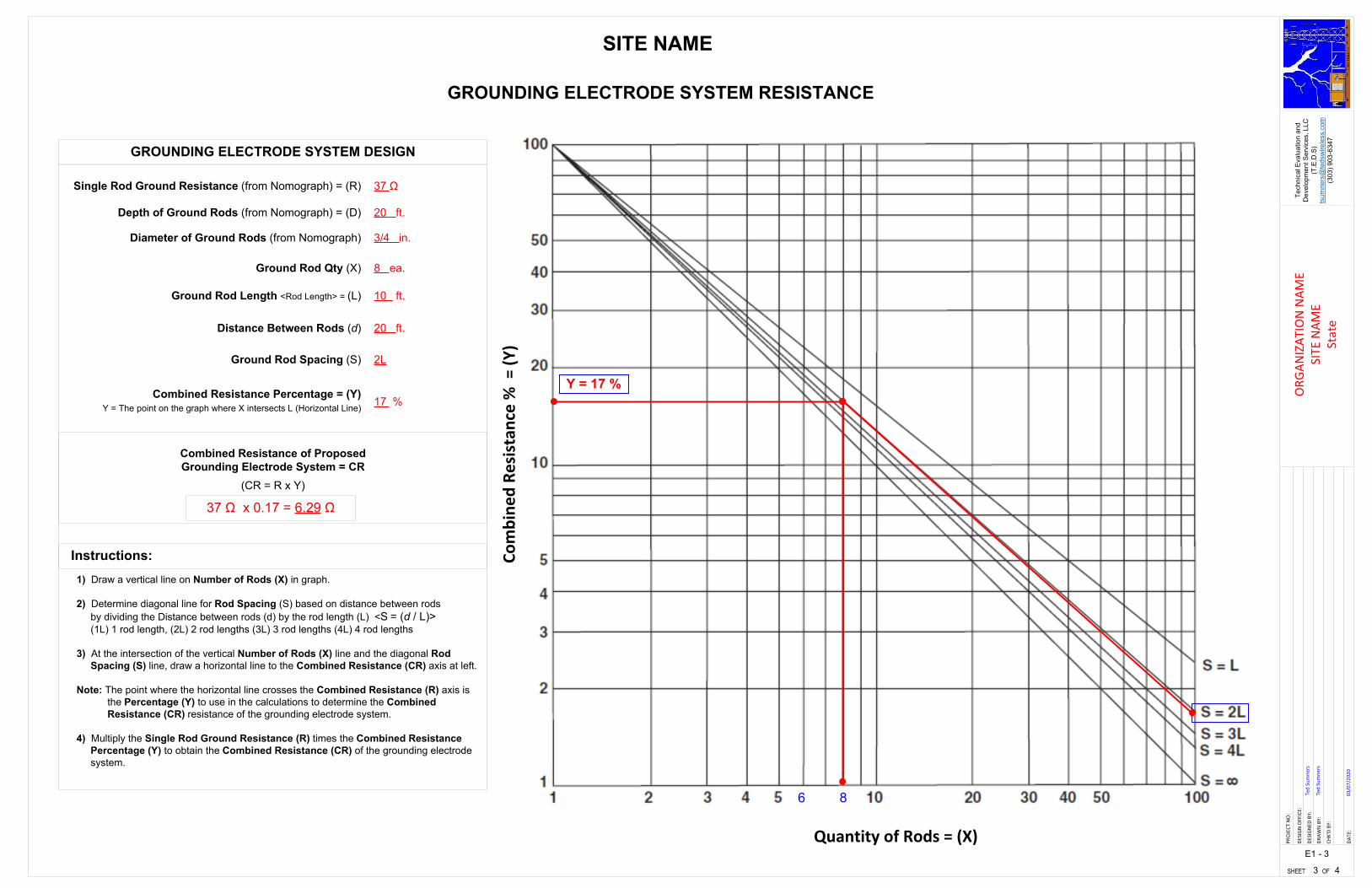
GROUNDING ELECTRODE SYSTEM RESISTANCE
Y = 17 %
6
17 %
(CR = R x Y)
Single Rod Ground Resistance (from Nomograph) = (R) 37 Ω
Combined Resistance of Proposed Grounding Electrode System = CR
Ground Rod Spacing (S) 2L
Ground Rod Qty (X) 8 ea.
Combined Resistance Percentage = (Y)Y = The point on the graph where X intersects L (Horizontal Line)
Ground Rod Length <Rod Length> = (L) 10 ft.
Distance Between Rods (d) 20 ft.
8
37 Ω x 0.17 = 6.29 Ω
SITE NAME
Depth of Ground Rods (from Nomograph) = (D) 20 ft.
Diameter of Ground Rods (from Nomograph) 3/4 in.
1) Draw a vertical line on Number of Rods (X) in graph.
2) Determine diagonal line for Rod Spacing (S) based on distance between rods by dividing the Distance between rods (d) by the rod length (L) <S = (d / L)> (1L) 1 rod length, (2L) 2 rod lengths (3L) 3 rod lengths (4L) 4 rod lengths
3) At the intersection of the vertical Number of Rods (X) line and the diagonal Rod Spacing (S) line, draw a horizontal line to the Combined Resistance (CR) axis at left.
Note: The point where the horizontal line crosses the Combined Resistance (R) axis is the Percentage (Y) to use in the calculations to determine the Combined Resistance (CR) resistance of the grounding electrode system.
4) Multiply the Single Rod Ground Resistance (R) times the Combined Resistance Percentage (Y) to obtain the Combined Resistance (CR) of the grounding electrode system.
GROUNDING ELECTRODE SYSTEM DESIGN
Instructions:
Quantity of Rods = (X)
Combine
d Re
sistan
ce % = (Y
)
ORG
ANIZAT
ION NAM
ESITE NAM
EState
Tech
nica
l Eva
luat
ion
and
Dev
elop
men
t Ser
vice
s, L
LC
(T.E
.D.S
)ts
umne
rs@
teds
wire
less
.com
(303
) 903
-634
7

7
3
Ground Electrical Pass-Thru Bus Bar to Ground Ring 5
Install Tower Ground Bus Bar at Base of Antenna Mast
Ground Shelter Ground Tab to Ground Ring
5
Ground Shelter Ground Tab to Ground Ring
5
1
1B
1B
240 in.
1B
GROUNDING ELECTRODE SYSTEM DESIGN WITH RADIALS
1
1
1B
E3
CHK'D BY
:
DESIGN OFFICE:
DESIGNED
BY:
PROJECT
NO:
DRAW
N BY:
APPR
OVE
D BY:
DATE:
3/4 in.
Typical Ground Rod¾ in. Diameter 10 ft. Long
30 in. Deep Trench
10 ft
Grade
1
5 #2 AWG, Bare, Solid, Tinned Copper Grounding Conductor
7Shelter Ground Ring #2 AWG, Bare, Solid, Tinned Copper Grounding Conductor
1BConcrete Encased Electrode Bonded to Ground Ring
6 in
12 Feet
240 in.
1
Radial Ground with Three 10 ft. Long Ground Rods Spaced 20 ft. Apart
Radial Ground with Two 10 ft. Long Ground Rods Spaced 20 ft. Apart
Radial Ground with Three 10 ft. Long Ground Rods Spaced 20 ft. Apart
15 Rods: 256.6Ω x 0.095 = 24.4 Ω
Radial Ground with Three 10 ft. Long Ground Rods Spaced 20 ft. Apart
4 4
Ted Sumne
rsTed Sumne
rs
03/07/20
20
SITE NAME
ORG
ANIZAT
ION NAM
ESITE NAM
EState
Tech
nica
l Eva
luat
ion
and
Dev
elop
men
t Ser
vice
s, L
LC
(T.E
.D.S
)ts
umne
rs@
teds
wire
less
.com
(303
) 903
-634
7
E1 - 2
CHK'D BY
:
DESIGN OFFICE:
DESIGNED
BY:
PROJECT
NO:
DRAW
N BY:
APPR
OVE
D BY
:
DATE:
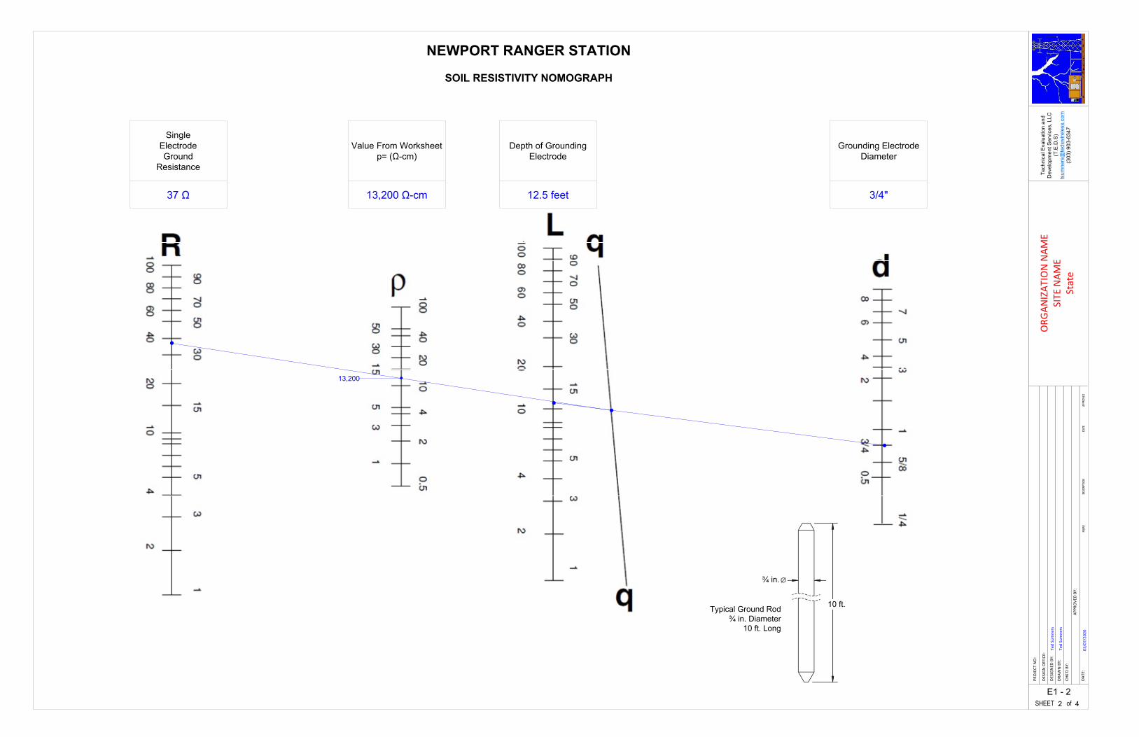
SOIL RESISTIVITY NOMOGRAPH
NEWPORT RANGER STATION
Grounding Electrode Diameter
Depth of Grounding Electrode
Value From Worksheetp= (Ω-cm)
13,200 Ω-cm 12.5 feet 3/4"
Single Electrode Ground
Resistance
37 Ω
13,200
10 ft.
¾ in.
Typical Ground Rod¾ in. Diameter
10 ft. Long
Ted Sumne
rs
Ted Sumne
rs
03/07/20
20
2 4
ORG
ANIZAT
ION NAM
ESITE NAM
EState
Tech
nica
l Eva
luat
ion
and
Dev
elop
men
t Ser
vice
s, L
LC
(T.E
.D.S
)ts
umne
rs@
teds
wire
less
.com
(303
) 903
-634
7

E1 - 3
CHK'D BY
:
DESIGN OFFICE:
DESIGNED
BY:
PROJECT
NO:
DRAW
N BY:
APPR
OVE
D BY
:
DATE:
GROUNDING ELECTRODE SYSTEM RESISTANCE
Y = 17 %
6
17 %
(CR = R x Y)
Single Rod Ground Resistance (from Nomograph) = (R) 37 Ω
Combined Resistance of Proposed Grounding Electrode System = CR
Ground Rod Spacing (S) 2L
Ground Rod Qty (X) 8 ea.
Combined Resistance Percentage = (Y)Y = The point on the graph where X intersects L (Horizontal Line)
Ground Rod Length <Rod Length> = (L) 10 ft.
Distance Between Rods (d) 20 ft.
8
37 Ω x 0.17 = 6.29 Ω
NEWPORT RANGER STATION
CHK'D BY
:
DESIGN OFFICE:
DESIGNED
BY:
PROJECT
NO:
DRAW
N BY:
DATE:
Ted Sumne
rs
Ted Sumne
rs
03/07/20
20
3 4
Depth of Ground Rods (from Nomograph) = (D) 20 ft.
Diameter of Ground Rods (from Nomograph) 3/4 in.
1) Draw a vertical line on Number of Rods (X) in graph.
2) Determine diagonal line for Rod Spacing (S) based on distance between rods by dividing the Distance between rods (d) by the rod length (L) <S = (d / L)> (1L) 1 rod length, (2L) 2 rod lengths (3L) 3 rod lengths (4L) 4 rod lengths
3) At the intersection of the vertical Number of Rods (X) line and the diagonal Rod Spacing (S) line, draw a horizontal line to the Combined Resistance (CR) axis at left.
Note: The point where the horizontal line crosses the Combined Resistance (R) axis is the Percentage (Y) to use in the calculations to determine the Combined Resistance (CR) resistance of the grounding electrode system.
4) Multiply the Single Rod Ground Resistance (R) times the Combined Resistance Percentage (Y) to obtain the Combined Resistance (CR) of the grounding electrode system.
GROUNDING ELECTRODE SYSTEM DESIGN
Instructions:
Quantity of Rods = (X)
Combine
d Re
sistan
ce % = (Y
)
ORG
ANIZAT
ION NAM
ESITE NAM
EState
Tech
nica
l Eva
luat
ion
and
Dev
elop
men
t Ser
vice
s, L
LC
(T.E
.D.S
)ts
umne
rs@
teds
wire
less
.com
(303
) 903
-634
7

Fall-of-Potential Ground Resistance Field Report
Date of Test:
Radio Facility Name:
Conditions:
Test Configuration:
Test Company:
Test Instrument Manufacterer: Tester Name:
Serial Number:
Calibration Date:
Resistance Requirement:
Test Instrument Model:
Test Procedure:
Facility Type:
TESTING RESULTS – PASSED or Failed at 27 Ohms
Fox Mountain
09/15/2019
Remote Radio Facility
Z- Probe set 60 ft. from grounding system
Technical Evaluation and Development Services (T.E.D.S. LLC)
Ted SumnersExtech
10 or 25 Ohms
Slope Method (Intersecting Curves)Y-Probe moved in 20% increments to obtain values R1, R2 and R3
Calculations made to obtain True Resistance Distance
GRT300
Y Probe Distance (ft.)10 15 20 25 30 35 40
Resistance (Ω)
10
15
20
25
5
45
R2 = 20.3Ω
Y Probe
Z Probe50 ft.
R1 = 27 Ω
2/1/2019
Dry, 52 Degrees
1804667
R3 = 16.4Ω
True Resistance at xx ft.
Name: Ted Sumners Signature: Date: 09/15/2019
Certification: I certify the results depicted on this form regarding grounding system testing and resulting calculations to be accurate and true.
Technical Evaluation and Development Services, LLC (T.E.D.S)[email protected] – (303) 903-6347


