Proceedings of IOE Graduate Conference, 2015 pp. 75–87 Soil Structure Interaction and Seismic Design Code Provision Sagar Karki Chhetri 1 , Kamal Bahadur Thapa 2 1,2 Department of Civil Engineering, Pulchowk Campus, Institute of Engineering, Tribhuvan University, Nepal Corresponding Email: 1 [email protected]Abstract The current seismic design code neglect the SSI effect and consider the base of structure as fixed one. It tacitly assumes that increase in fundamental Time period of building structures due to SSI effect including the increase in damping characteristics of soil would be beneficial always. This consideration is applicable for light structure in stiff soil but may not hold good for certain class of structure with different soil type. Also most of the buildings are designed considering the smooth response spectra curves as per seismic code. Great earthquake as Kobe earthquake 1995, Mexico earthquake 1985 showed some different behavior deviating from the above response spectra. The 1985 Mexico City earthquake mainly affect the mid-rise building in Mexico City. Whereas the Mexico City lies in old lake bed which is the soft clay. Nepal is the country with high risk of earthquake and Kathmandu valley lies above the soft soil deposit is very much liable to resonance of the structure. The Kathmandu valley consists of many strata of sand, silt and clay sediments, which bring forward a possibility that two or more amplified frequencies occur during an earthquake. This research focuses to know the effect of SSI on the response of heavy structure in different soil strata condition subjected to earthquake ground motion acceleration. Three types of mid-rise moment-resisting building frames, including 5-Storey, 10-Storey and 15-Storey buildings are selected. The bare frame model and frame shear wall modelled and analyzed, employing finite element method under two different boundary condition: (a) fixed base (no SSI) and (b) considering SSI. From the results obtained shows that the SSI plays a considerable role in seismic behavior of mid-rise buildings. Thus, considering SSI effects in the seismic design of mid-rise moment resisting building frames, particularly when resting on soft soil deposit, is essential. Keywords Soil Structure Interaction – Seismic Code Spectra – Resonance 1. Introduction The response of the structure to earthquake shaking is affected by interaction between three linked systems; the structure, the foundation and the soil underlying and surrounding the foundation. The process in which the response of the soil influences the motion of the structure and the motion of the structure influences the response of the soil is termed as soil-structure interaction (SSI). The interaction causes energy dissipation and changes the natural modes of vibration of the structure such as natu- ral frequencies and the corresponding mode shapes [1]. The research [2] regarding the role of SSI in the seismic performance of the structure discuss both the beneficial as well as detrimental role of SSI. Adopting the benefi- cial role of SSI, many seismic design codes suggested to neglect SSI effects assumes the building to be fixed at their bases. Which is a conservative simplification that would supposedly lead to improved safety margins. The IS: 1893-2002 seismic design code also adopt the same beneficial role of SSI in analysis but it further states that, “However there are some exception where Resonance like conditions have been seen to occur between long distance waves and the Tall structures founded on deep Soft Soil”. Whereas, in reality supporting soil medium allows movement to some extent due to flexibility na- ture of the soil, which decrease the overall lateral stiff- ness of the structural system resulting in the lengthening of lateral natural periods. Such lengthening of lateral natural periods does considerably change the seismic response of building frames. The resonance effect on the structure becomes prominent by soil amplification
Transcript
Proceedings of IOE Graduate Conference, 2015pp. 75–87
Soil Structure Interaction and Seismic Design Code Provision
Sagar Karki Chhetri1, Kamal Bahadur Thapa2
1,2Department of Civil Engineering, Pulchowk Campus, Institute of Engineering, Tribhuvan University, NepalCorresponding Email: [email protected]
AbstractThe current seismic design code neglect the SSI effect and consider the base of structure as fixed one. It tacitlyassumes that increase in fundamental Time period of building structures due to SSI effect including the increasein damping characteristics of soil would be beneficial always. This consideration is applicable for light structure instiff soil but may not hold good for certain class of structure with different soil type. Also most of the buildingsare designed considering the smooth response spectra curves as per seismic code. Great earthquake as Kobeearthquake 1995, Mexico earthquake 1985 showed some different behavior deviating from the above responsespectra. The 1985 Mexico City earthquake mainly affect the mid-rise building in Mexico City. Whereas the MexicoCity lies in old lake bed which is the soft clay. Nepal is the country with high risk of earthquake and Kathmanduvalley lies above the soft soil deposit is very much liable to resonance of the structure. The Kathmandu valleyconsists of many strata of sand, silt and clay sediments, which bring forward a possibility that two or more amplifiedfrequencies occur during an earthquake. This research focuses to know the effect of SSI on the response ofheavy structure in different soil strata condition subjected to earthquake ground motion acceleration. Three typesof mid-rise moment-resisting building frames, including 5-Storey, 10-Storey and 15-Storey buildings are selected.The bare frame model and frame shear wall modelled and analyzed, employing finite element method under twodifferent boundary condition: (a) fixed base (no SSI) and (b) considering SSI. From the results obtained showsthat the SSI plays a considerable role in seismic behavior of mid-rise buildings. Thus, considering SSI effects inthe seismic design of mid-rise moment resisting building frames, particularly when resting on soft soil deposit, isessential.
The response of the structure to earthquake shaking isaffected by interaction between three linked systems;the structure, the foundation and the soil underlying andsurrounding the foundation. The process in which theresponse of the soil influences the motion of the structureand the motion of the structure influences the response ofthe soil is termed as soil-structure interaction (SSI). Theinteraction causes energy dissipation and changes thenatural modes of vibration of the structure such as natu-ral frequencies and the corresponding mode shapes [1].
The research [2] regarding the role of SSI in the seismicperformance of the structure discuss both the beneficialas well as detrimental role of SSI. Adopting the benefi-cial role of SSI, many seismic design codes suggested to
neglect SSI effects assumes the building to be fixed attheir bases. Which is a conservative simplification thatwould supposedly lead to improved safety margins. TheIS: 1893-2002 seismic design code also adopt the samebeneficial role of SSI in analysis but it further states that,“However there are some exception where Resonancelike conditions have been seen to occur between longdistance waves and the Tall structures founded on deepSoft Soil”. Whereas, in reality supporting soil mediumallows movement to some extent due to flexibility na-ture of the soil, which decrease the overall lateral stiff-ness of the structural system resulting in the lengtheningof lateral natural periods. Such lengthening of lateralnatural periods does considerably change the seismicresponse of building frames. The resonance effect onthe structure becomes prominent by soil amplification
Soil Structure Interaction and Seismic Design Code Provision
even though the soil has good engineering characteristics[3]. The report [4] & [5] discusses about the theoreticalbackground of seismic design as per IS & NNBC coderespectively. The report further illustrate the resonancevibration of building and variation in nature of designresponse spectra and response spectra from various longperiod earthquake. The possible severities of neglectingthe effects of the SSI are fore grounded in previous re-search works [6] & [7]. The result of the research work[8]& [9] provides the necessary amendment to be donein seismic design code of Iran & Australia respectivelyfor seismic analysis of building considering soil structureinteraction. The variation in time period and base shearfor two adjacent tall building kept at certain distance dueto soil structure interaction was done in research [10].So this work focus on the behavior of the tall buildingconsidering the SSI effect. The effect of soil-flexibilityis accounted through consideration of springs of spec-ified stiffness as prescribed in well-accepted literature[11] & [12]. The present study has been carried out forbuildings with the same geometry found on varying soiltypes over raft foundations in Zone V. An attempt hasbeen made to find the variation in Time period, Storeydisplacement & Storey drift under seismic loading in thestructure and raft foundation by incorporating the effectof soil-structure interaction which was further comparedwith those of fixed base condition. Influence of variationof the parameters such as, different soil conditions andnumber of stories were also considered in the presentstudy for which the buildings were modelled by fouralternate approaches, namely, (1) bare frame with fixedsupports, (2) bare frame with supports accounting forsoil-flexibility, (3) frame-shear wall with fixed supportsand (4) frame-shear wall with supports accounting forsoil-flexibility.
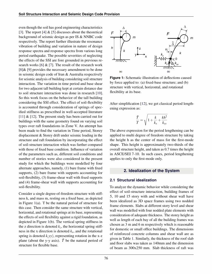
Consider a single degree-of-freedom structure with stiff-ness k, and mass m, resting on a fixed base, as depictedin Figure 1(a). T be the natural period of structure forthis case. Then consider the same structure with vertical,horizontal, and rotational springs at its base, representingthe effects of soil flexibility against a rigid foundation, asdepicted in Figure 1(b). The vertical spring stiffness inthe z direction is denoted kz, the horizontal spring stiff-ness in the x direction is denoted kx, and the rotationalspring is denoted k(yy), representing rotation in the x-zplane (about the y-y axis). T be the natural period ofstructure for flexible base.
Figure 1: Schematic illustration of deflections causedby force applied to: (a) fixed-base structure; and (b)structure with vertical, horizontal, and rotationalflexibility at its base.
After simplification [12], we get classical period length-ening expression as:
TT
=
√1+
kkx
+kh2
kyy
The above expression for the period lengthening can beapplied to multi degree of freedom structure by takingthe height h as the center of mass for the first-modeshape. This height is approximately two-thirds of theoverall structure height, and taken as 0.7 times the heightin ASCE/SEI 7-10. In such cases, period lengtheningapplies to only the first-mode only.
2. Idealization of the System
2.1 Structural idealization
To analyze the dynamic behavior while considering theeffect of soil-structure interaction, building frames of5, 10 and 15 story with and without shear wall havebeen idealized as 3D space frames using two noddedframe elements. Slabs at different story level and shearwall was modelled with four nodded plate elements withconsideration of adequate thickness. The storey height aswell as length of each bay of all the building frames waschosen as 3 m and 6 m respectively which is reasonablefor domestic or small office buildings. The dimensionsof reinforced concrete columns and shear wall are asgiven in Table 1. Similarly, the thickness of the roof slaband floor slabs was taken as 140mm and the dimensionof beam as 300x250 mm. Slab thickness of raft was
76
Proceedings of IOE Graduate Conference, 2015
taken as 1 m. M20 grade of concrete for beam , M25grade of concrete for column with Fe500 grade of rebarmaterial is considered. These dimensions were arrivedon the basis of the design following the respective Indiancode [13] for design of reinforced concrete structures.
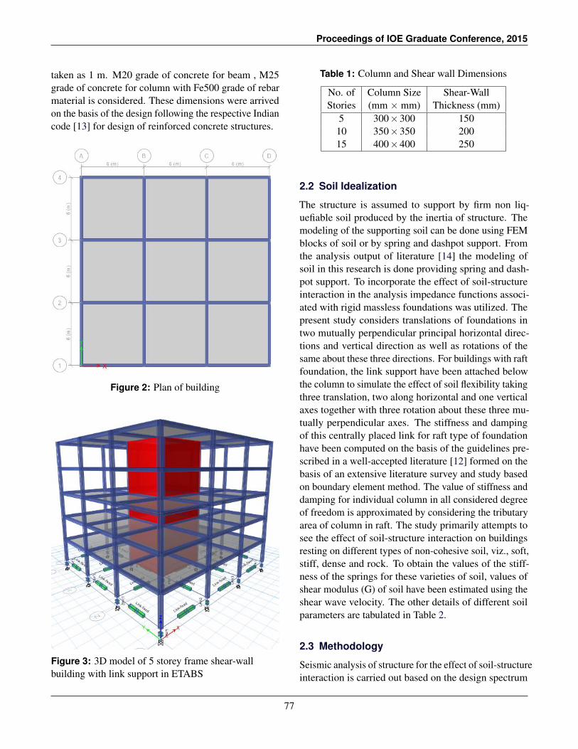
Figure 2: Plan of building
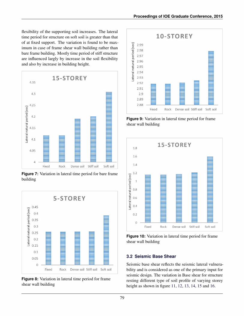
Figure 3: 3D model of 5 storey frame shear-wallbuilding with link support in ETABS
Table 1: Column and Shear wall Dimensions
No. of Column Size Shear-WallStories (mm × mm) Thickness (mm)
5 300×300 15010 350×350 20015 400×400 250
2.2 Soil Idealization
The structure is assumed to support by firm non liq-uefiable soil produced by the inertia of structure. Themodeling of the supporting soil can be done using FEMblocks of soil or by spring and dashpot support. Fromthe analysis output of literature [14] the modeling ofsoil in this research is done providing spring and dash-pot support. To incorporate the effect of soil-structureinteraction in the analysis impedance functions associ-ated with rigid massless foundations was utilized. Thepresent study considers translations of foundations intwo mutually perpendicular principal horizontal direc-tions and vertical direction as well as rotations of thesame about these three directions. For buildings with raftfoundation, the link support have been attached belowthe column to simulate the effect of soil flexibility takingthree translation, two along horizontal and one verticalaxes together with three rotation about these three mu-tually perpendicular axes. The stiffness and dampingof this centrally placed link for raft type of foundationhave been computed on the basis of the guidelines pre-scribed in a well-accepted literature [12] formed on thebasis of an extensive literature survey and study basedon boundary element method. The value of stiffness anddamping for individual column in all considered degreeof freedom is approximated by considering the tributaryarea of column in raft. The study primarily attempts tosee the effect of soil-structure interaction on buildingsresting on different types of non-cohesive soil, viz., soft,stiff, dense and rock. To obtain the values of the stiff-ness of the springs for these varieties of soil, values ofshear modulus (G) of soil have been estimated using theshear wave velocity. The other details of different soilparameters are tabulated in Table 2.
2.3 Methodology
Seismic analysis of structure for the effect of soil-structureinteraction is carried out based on the design spectrum
77
Soil Structure Interaction and Seismic Design Code Provision
Table 2: Detail of soil parameter considered
Shear wave Poission’s Mass densityDescription velocity Vs ratio (ρ) KN/m3
provided in IS: 1893-2002. The seismic analysis of thesebuildings are obtained due to the design spectrum corre-sponding to 5% of critical damping [13]. The mediumcategory type of soil is taken in consideration
Figure 4: Design Response Spectrum From IS:1893-2002
Both static method and Response Spectrum method ofseismic analysis are performed by applying seismic zonefactor value 0.36 for very severe seismic intensity, re-duction factor 5 for both special RC moment resistingframe & ductile shear wall with SMRF with importancefactor 1.
The linear time history analysis is performed for allthe models. The ground motion data of Mexico Cityearthquake 1985 is used and shown in figure 29.
3. Results and Discussions
After the modeling of the structure for the various bound-ary condition, the analysis of the model are done and theresults are represent as the function of number of storiesand types of soil.
3.1 Lateral natural period
Idealization of building as a bare frame is unrealistic,but such idealization is used many time in the designoffices. So, study has been made for such frames andframe shear wall building. The variation in fundamentaltime period for structure resting different type of soilprofile of varying storey height as shown in figure 5, 6,7, 8, 9 and 10.
Figure 5: Variation in lateral time period for bare framebuilding
Figure 6: Variation in lateral time period for bare framebuilding
The lateral time period of the building increase as the
78
Proceedings of IOE Graduate Conference, 2015
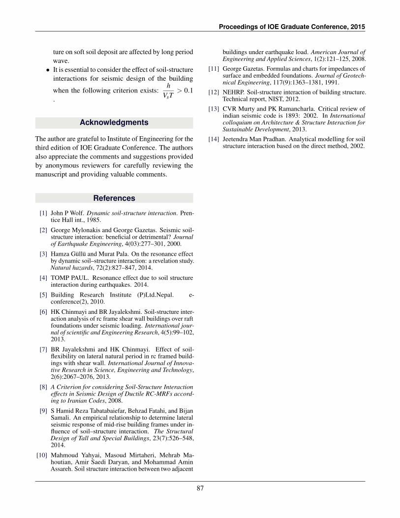
flexibility of the supporting soil increases. The lateraltime period for structure on soft soil is greater than thatof at fixed support. The variation is found to be max-imum in case of frame shear wall building rather thanbare frame building. Mostly time period of stiff structureare influenced largly by increase in the soil flexibilityand also by increase in building height.
Figure 7: Variation in lateral time period for bare framebuilding
Figure 8: Variation in lateral time period for frameshear wall building
Figure 9: Variation in lateral time period for frameshear wall building
Figure 10: Variation in lateral time period for frameshear wall building
3.2 Seismic Base Shear
Seismic base shear reflects the seismic lateral vulnera-bility and is considered as one of the primary input forseismic design. The variation in Base shear for structureresting different type of soil profile of varying storeyheight as shown in figure 11, 12, 13, 14, 15 and 16.
79
Soil Structure Interaction and Seismic Design Code Provision
Figure 11: Variation in seismic base shear for bareframe building
Figure 12: Variation in seismic base shear for bareframe wall building
The decrease in base shear is due to displacement offoundation on flexible soil. The study shows that de-crease in base shear for same building is more in case offrame shear wall building than bare frame mode havingsame type of foundation support. There is significant
decrease in the value of base shear due to increase inflexibility of soil( rock, dense and stiff soil) for the frameshear wall building but lesser decrease in the value forbare frame building.
Figure 13: Variation in seismic base shear for bareframe wall building
Figure 14: Variation in seismic base shear for frameshear wall building
80
Proceedings of IOE Graduate Conference, 2015
Figure 15: Variation in seismic base shear for frameshear wall building
Figure 16: Variation in seismic base shear for frameshear wall building
3.3 Storey displacement
The variation in storey displacement along horizontalx-direction for structure resting in different type of soilprofile of varying storey height as shown in figure 17,18, 19, 20, 21 and 22.
Figure 17: Variation in lateral storey displacement forbare frame building
Figure 18: Variation in lateral storey displacement forbare frame building
The deformation due to both static method and Responsespectrum method are taken in consideration. The graphshows the comparison between structures in soft soildeposit and fixed type support of system. The variation
81
Soil Structure Interaction and Seismic Design Code Provision
in storey displacement due to soil flexibility is smallervalue in case of lower storey level for bare frame model.
Figure 19: Variation in lateral storey displacement forbare frame building
Figure 20: Variation in lateral storey displacement forframe shear wall building
The variation pattern of storey displacement is uniformin case of bare frame building but in frame shear wallbuilding the variation is not uniform. The deflected
shape of the bare frame building is different than that offrame shear wall building.
Figure 21: Variation in lateral storey displacement forframe shear wall building
Figure 22: Variation in lateral storey displacement forframe shear wall building
Note: In graph fixed rs refers to fixed base support for re-sponse spectrum method, Soft Static refers to Soft base sup-port for static earthquake loading method and respectively forother case.
82
Proceedings of IOE Graduate Conference, 2015
3.4 Storey drift
The variation in storey drift along the horizontal x-directionfor structure resting in different type of soil profile ofvarying storey height as shown in figure 23, 24, 25, 26,27 and 28.
Figure 23: Variation in lateral storey drift for bareframe building
Figure 24: Variation in lateral storey drift for bareframe building
Figure 25: Variation in lateral storey drift for bareframe building
Figure 26: Variation in lateral storey drift for frameshear wall building
The drift due to both static method and Response spec-trum method are taken in consideration. The graphshows the comparison between structure in soft soil de-posit and fixed type support of system. The variationpattern of storey displacement is uniform in case of bareframe building but in frame shear wall building the vari-ation is not uniform. For the bare frame building, the
83
Soil Structure Interaction and Seismic Design Code Provision
maximum storey drift lies in the lower storey level i.e.,between 2nd and 4th storey level.
Figure 27: Variation in lateral storey drift for frameshear wall building
Figure 28: Variation in lateral storey drift for frameshear wall building
3.5 Time history analysis
The linear time history analysis is performed by lineardirect method of integration using Hilber Hughes Taylormethod along x-direction for all the models. The groundmotion data of Mexico City earthquake 1985 is used andshown in figure 29.
Figure 29: Ground acceleration time history forMexico City earthquake 1985
Response spectrum
The spectral acceleration of the top floor of the buildingdue to input ground motion for different soil supportcondition is as shown in figure 33, 34, 30, 31 and 32.Theresponse of the top floor of the building shows somedifferent nature than that of design spectrum from code.The seismic design spectra which attain constant accel-eration up to a certain period and thereafter decreasemonotonically with period but the predominant periodof the structure is more than that value from the code.The maximum ordinate of the actual spectra is more thanthe value given by the code. And from the graph, themaximum ordinate of response spectra curve tends todecrease as the flexibility of soil increases for bare framebuilding. The study of response spectrum curve for 5storey and 10 storey bare frame building shows maxi-mum ordinate than the design response spectrum. Theresponse spectra curve of 10 storey and 15 storey frameshear wall shows double point peak curve. These showsthat the stiff structure in soft soil deposit are liable toresonance twice. These multiple amplified frequenciesin a particular area can create a resonance effect both forlow rise as well as tall building. The soft soil modifiedthe incoming seismic waves such that resulting motionof the structure become detrimental. The local site am-plification must be taken in consideration for seismicdesign of the structure.
84
Proceedings of IOE Graduate Conference, 2015
Figure 30: Comparison of a seismic code designspectrum to actual spectra for Dense soil support,damping 5 %
Figure 31: Comparison of a seismic code designspectrum to actual spectra for Stiff soil support,damping 5 %
Figure 32: Comparison of a seismic code designspectrum to actual spectra for Soft soil support,damping 5 %
Figure 33: Comparison of a seismic code designspectrum to actual spectra for fixed soil support,damping 5 %
Figure 34: Comparison of a seismic code designspectrum to actual spectra for Rock soil support,damping 5 %
Note: In graph I, II & III refers to soil type in design responsespectrum of IS1893:2002, 5-bare refers to 5 storey buildingwith bare frame model, 5-sw refers to 5 storey building withframe shear model and respectively.
3.6 Soil Structure System Behavior
Considering h be the structure height, B & L refers tothe half-width and half-length of the foundation. T bethe first mode period of the structure and Vs be the shearwave velocity of soil below the foundation. The term h/T
85
Soil Structure Interaction and Seismic Design Code Provision
quantifies the stiffness of the superstructure and has theunit of velocity, the term h/(VsT) represents the structureto soil stiffness ratio. The term h/B represent the struc-ture height to foundation width ratio. Using differentmodels for square footing (L=B) the period lengtheningratios can be calculated considering dimensionless pa-rameter h/(VsT) and h/B and plotted in the figure 35 and36.
Figure 35: Plot of period lengthening ratio versusstructure-to-soil stiffness ratio for square footing andvarying ratio of h/B (for Bare frame model)
Figure 36: Plot of period lengthening ratio versusstructure-to-soil stiffness ratio for square footing andvarying ratio of h/B (for frame shear wall model)
From the graph stiff structure on the soft soil deposit aremore affected by period lengthening than the structureon the rigid support. Whereas flexible structure are lessaffected as compared to stiff structure. As the valueof h/B increase that means more slender the structurebecome greater the value of period lengthening. Tall andhigh rise structure are more influenced than the short andlow rise building due to soil flexibility.
The natural period of ground varies from about 0.4 sec-
onds up to 2 seconds, depending on the nature of theground. Hard ground or rock will experience short pe-riod vibration. Very soft ground may have a period ofup to 2 seconds but, unlike a structure, it cannot sus-tain longer period motions except under certain unusualconditions. Since this range is well within the range ofcommon building periods, it is quite possible that thepushes that earthquake ground motion imparts to thebuilding will be at the natural period of the building.The period lengthening of the building due to soil struc-ture interaction cause the increase in natural period ofbuilding. This may create resonance of the building withthe ground motion, causing the structure to encounteraccelerations of perhaps 1g when the ground is onlyvibrating with accelerations of 0.2g. Because of this,buildings suffer the greatest damage from ground mo-tion at a frequency close or equal to their own naturalfrequency. Thus the predominant frequency of groundmotion acceleration leading to the enhanced vibration ofthe structure and higher possibilities of collapse.
4. Conclusion
The present study makes an effort to evaluate the effectof soil structure interaction on the seismic behavior ofbare frame buildings and building with frame-shear wallof varying height over varying soil property on raft foun-dation. The scope of the work is to highlight rather thanfully resolve the role of SSI. After the observation ofthe change in lateral natural period, seismic base shear,storey displacement and storey drift the following con-clusion were drawn.
• The variation in fundamental period, seismic baseshear & storey displacement of the building in-creases with the reduction in stiffness of soil.
• The variation of storey drift is more in case ofshear frame building on fixed soil support than thesoft soil support corresponding to same type offrame building on same type of soil profile.
• The stiff structure are more affected by the soilstructure interaction.
• These increase in fundamental period of structurein soft soil deposit leads to resonance of the build-ing for long period ground motion.
• The stiff structure on hard rock support is more af-fected by short period wave and the flexible struc-
86
Proceedings of IOE Graduate Conference, 2015
ture on soft soil deposit are affected by long periodwave.
• It is essential to consider the effect of soil-structureinteractions for seismic design of the building
when the following criterion exists:h
VsT> 0.1
.
Acknowledgments
The author are grateful to Institute of Engineering for thethird edition of IOE Graduate Conference. The authorsalso appreciate the comments and suggestions providedby anonymous reviewers for carefully reviewing themanuscript and providing valuable comments.
References
[1] John P Wolf. Dynamic soil-structure interaction. Pren-tice Hall int., 1985.
[2] George Mylonakis and George Gazetas. Seismic soil-structure interaction: beneficial or detrimental? Journalof Earthquake Engineering, 4(03):277–301, 2000.
[3] Hamza Gullu and Murat Pala. On the resonance effectby dynamic soil–structure interaction: a revelation study.Natural hazards, 72(2):827–847, 2014.
[4] TOMP PAUL. Resonance effect due to soil structureinteraction during earthquakes. 2014.
[5] Building Research Institute (P)Ltd.Nepal. e-conference(2), 2010.
[6] HK Chinmayi and BR Jayalekshmi. Soil-structure inter-action analysis of rc frame shear wall buildings over raftfoundations under seismic loading. International jour-nal of scientific and Engineering Research, 4(5):99–102,2013.
[7] BR Jayalekshmi and HK Chinmayi. Effect of soil-flexibility on lateral natural period in rc framed build-ings with shear wall. International Journal of Innova-tive Research in Science, Engineering and Technology,2(6):2067–2076, 2013.
[8] A Criterion for considering Soil-Structure Interactioneffects in Seismic Design of Ductile RC-MRFs accord-ing to Iranian Codes, 2008.
[9] S Hamid Reza Tabatabaiefar, Behzad Fatahi, and BijanSamali. An empirical relationship to determine lateralseismic response of mid-rise building frames under in-fluence of soil–structure interaction. The StructuralDesign of Tall and Special Buildings, 23(7):526–548,2014.
[10] Mahmoud Yahyai, Masoud Mirtaheri, Mehrab Ma-houtian, Amir Saedi Daryan, and Mohammad AminAssareh. Soil structure interaction between two adjacent
buildings under earthquake load. American Journal ofEngineering and Applied Sciences, 1(2):121–125, 2008.
[11] George Gazetas. Formulas and charts for impedances ofsurface and embedded foundations. Journal of Geotech-nical Engineering, 117(9):1363–1381, 1991.
[12] NEHRP. Soil-structure interaction of building structure.Technical report, NIST, 2012.
[13] CVR Murty and PK Ramancharla. Critical review ofindian seismic code is 1893: 2002. In Internationalcolloquium on Architecture & Structure Interaction forSustainable Development, 2013.
[14] Jeetendra Man Pradhan. Analytical modelling for soilstructure interaction based on the direct method, 2002.