Journal of Engineering Volume 19 July 2013 Number 7 795 Soil-Structure Interaction of Retaining Walls under Earthquake Loads Prof. Dr. Adnan Falih Ali Mohammed Asaad Mohammed [email protected][email protected]Mohammed University of Baghdad ABSTRACT The study is devoted to both static and earthquake response analysis of retaining structures acted upon by lateral earth pressure. Two main approaches were implemented in the analysis, namely, the Mononobe-Okabe analytical method and the numerical Finite element procedure as provided in the ready software ABAQUS with explicit dynamic method. A basic case study considered in the present work is the bridge approach retaining walls as a part of AL-Jadiriya bridge intersection to obtain the effects of the backfill and the ground water on the retaining wall response including displacement of the retaining structure in addition to the behavior of the fill material. Parametric studies were carried out to evaluate the effects of several factors such as vertical and horizontal components of the earthquake, maximum peak acceleration, angle of friction, damping ratio, height of the wall and groundwater level within the medium of fill. Three heights of retaining walls were considered for those above mentioned factors, these are (2.9m, 4.7m and6.7m). A comparison is made between the responses obtained on the basis of finite element analysis with those obtained using the Mononobe-Okabe method. It is found that the lateral wall responses obtained using the FE were larger than those calculated by the Mononobe-Okabe method for all heights of the retaining wall, it was also found that pore pressure of the ground water depends on the water flow through the backfill during the earthquake. The distribution of the dynamic earth pressure on the wall is nonlinear and depends on the earthquake ground acceleration in addition to the wall height and soil properties. Based on the numerical analysis and the results obtained from the parametric studies carried out, two expressions are proposed to evaluate the maximum lateral wall response in terms of wall height, soil properties and earthquake base excitation acceleration, and hence the dynamic earth pressure acting on the retaining structure. KEYWORDS: Earthquake, lateral earth pressure, Mononobe -Okabe, pore pressure, Retaining Wall ﺗﺪﺍﺧﻞ ﺍﻟﺠﺪﺭﺍﻥ ﺍﻟﺴﺎﻧﺪﺓ ﻟﻠﻤﻨﺸﺌﺎﺕ ﻣﻊ ﺍﻟﺘﺮﺑﺔ ﺗﺤﺖ ﺗﺄﺛﻴﺮ ﺍﻟﻬﺰﺍﺕ ﺃﻻﺭﺿﻴﺔ ﺍ.ﺩ. ﻋﺪﻧﺎﻥ ﻓﺎﻟﺢ ﻋﻠﻲ ﻣﺤﻤﺪ ﺍﺳﻌﺪ ﻣﺤﻤﺪ ﺍﻟﺨﻼﺻﺔ ﻛﺮﺳﺖ ﻫﺬﺓ ﺍﻟﺪﺭﺍﺳﺔ ﻟﻤﻌﺮﻓﺔ ﺍﺳﺘﺠﺎﺑﺔ ﺍﻟﻤﻨﺸﺌﺎﺕ ﺍﻟﺴﺎﻧﺪﺓ ﺍﻟﻮﺍﻗﻌﺔ ﺗﺤﺖ ﺗﺎﺛﻴﺮ ﺿ ﻐﻂ ﺍﻟﺘﺮﺑﺔ ﺍﻟﺠﺎﻧﺒﻲ ﻟ ﻠﺤﺎﻟﺘﻴﻴﻦ ﺍﻻﺳﺘﺎﺗﻴﻜﻴ ﺔ ﻭ ﺍﺛﻨﺎء ﺍﻟﻬﺰﺓ ﺍﻻﺭﺿﻴﺔ، ﻟﻘﺪ ﺗﻢ ﺍﺳﺘﺨﺪﺍﻡ ﻁﺮﻳﻘﺘﻴﻴﻦ ﻓﻲ ﺍﻟﺘﺤﻠﻴﻞ، ﻫﻤﺎ ﻁﺮﻳﻘﺔM-O ﺍﻟﺘﺤﻠﻴﻠﻴﺔ ﻭﻁﺮﻳﻘﺔ ﺍﻟﻌﻨﺎﺻﺮ ﺍﻟﻤﺤﺪﺩﺓ ﺍﻟﻌﺪﺩﻳﺔ ﻭﺍﻟﻤﺘﻮﻓﺮﺓ ﻓﻲ ﺍﻟﺒﺮﻧﺎﻣﺞ ﺍﻟﺘﺤﻠﻴﻠﻲABAQUS ﻋﻦ ﻁﺮﻳﻖ ﺍﻟﺤﺰﻣﺔ ﺍﻟﻤﺤﺪﺩﺓ ﺍﻟﺪﻳﻨﺎﻣﻴﻜﻴﺔ. ﻟﻘﺪ ﺗﻢ ﺍﺧﺬ ﺣﺎﻟﺔ ﺩﺭﺍﺳﻴﺔ ﺑﺴﻴﻄ ﺔ ﻓﻲ ﻫﺬﺍ ﺍﻟﻌﻤﻞ ﻭﺍﻟﻤﺘﻤﺜﻠﺔ ﻓﻲ ﺍﻟﺠﺪﺭﺍﻥ ﺍﻟﺴﺎﻧﺪﺓ ﻟﻤﻘﺘﺮﺏ ﻣﺠﺴﺮ ﺍﻟﺠﺎﺩﺭﻳﺔ ﻟﻤﻌﺮﻓﺔ ﺗﺄﺛﻴﺮ ﺗﺮﺏ ﺍﻻﺳﻨﺎﺩ ﻭﺍﻟﻤﻴﺎﺓ ﺍﻟﺠﻮﻓﻴﺔ ﻋﻠﻰ ﺃﺳﺘﺠﺎﺑﺔ ﺍﻟﺠﺪﺭﺍﻥ ﺍﻟﺴﺎﻧﺪﺓ ﻭﺍﻟﻤﺘﻀﻤﻨﺔ ﺃﺯﺍﺣﺔ ﺍﻟﻤﻨﺸﺌﺎﺕ ﺍﻟﺴﺎﻧﺪﺓ ﺑﺄﻻﺿﺎﻓﺔ ﺍﻟﻰ ﺗﺼﺮﻑ ﺍﻟﻤﻮﺍﺩ ﺍﻻﻣﻼﺋﻴﺔ، ﺗﻢ ﺃﺟﺮﺍء ﺩﺭﺍﺳﺎﺕ ﻣﺤﺪﺩﺓ ﻟﻤﻌﺮﻓﺔ ﺗﺄﺛﻴﺮ ﻋﺪﺓ ﻋﻮﺍﻣﻞ ﻣﺘﻐﻴﺮﺓ ﻣ ﺜﻞ ﺍﻟﻤﺮﻛﺒﺔ ﺃﻻﻓﻘﻴﺔ ﻭﺍﻟﺸﺎﻗﻮﻟﻴﺔ ﻟﻠﻬﺰﺓ ﺃﻻﺭﺿﻴﺔ، ﺍﻗﺼﻰ ﺗﻌﺠﻴﻞ ﻟﻠﻬﺰﺓ ﺃﻻﺭﺿﺒﺔ، ﺯﺍﻭﻳﺔ ﺃﻻﺣﺘﻜﺎﻙ ﺍﻟﺪﺍﺧﻠﻲ ﻟﻠﺘﺮﺑﺔ، ﻣﻌﺎﻣﻞ ﺍﻟﺘﺨﻤﻴﺪ، ﺃﺭﺗﻔﺎﻉ ﺍﻟﺠﺪﺍﺭ) ﺍﻟﺴﺎﻧﺪ ﻭﻣﺴﺘﻮﻯ ﺍﻟﻤﻴﺎﺓ ﺍﻟﺠﻮﻓﻴﺔ. ﺛﻼﺛﺔ ﺃﺭﺗﻔﺎﻋﺎﺕ ﻣﺨﺘﻠﻔﺔ ﺗﻢ ﺃﺳﺘﻌﻤﺎﻟﻬﺎ ﻓﻲ ﺍﻟﺪﺭﺍﺳﺔ ﻫﻲ2.9 ﻡ ،4.7 ﻡ ﻭ6.7 .( ﻡ
Transcript
Journal of Engineering Volume 19 July 2013 Number 7
795
Soil-Structure Interaction of Retaining Walls under Earthquake Loads
ABSTRACT The study is devoted to both static and earthquake response analysis of retaining structures acted upon by lateral earth pressure. Two main approaches were implemented in the analysis, namely, the Mononobe-Okabe analytical method and the numerical Finite element procedure as provided in the ready software ABAQUS with explicit dynamic method. A basic case study considered in the present work is the bridge approach retaining walls as a part of AL-Jadiriya bridge intersection to obtain the effects of the backfill and the ground water on the retaining wall response including displacement of the retaining structure in addition to the behavior of the fill material. Parametric studies were carried out to evaluate the effects of several factors such as vertical and horizontal components of the earthquake, maximum peak acceleration, angle of friction, damping ratio, height of the wall and groundwater level within the medium of fill. Three heights of retaining walls were considered for those above mentioned factors, these are (2.9m, 4.7m and6.7m).
A comparison is made between the responses obtained on the basis of finite element analysis with those obtained using the Mononobe-Okabe method. It is found that the lateral wall responses obtained using the FE were larger than those calculated by the Mononobe-Okabe method for all heights of the retaining wall, it was also found that pore pressure of the ground water depends on the water flow through the backfill during the earthquake. The distribution of the dynamic earth pressure on the wall is nonlinear and depends on the earthquake ground acceleration in addition to the wall height and soil properties. Based on the numerical analysis and the results obtained from the parametric studies carried out, two expressions are proposed to evaluate the maximum lateral wall response in terms of wall height, soil properties and earthquake base excitation acceleration, and hence the dynamic earth pressure acting on the retaining structure.
تداخل الجدران الساندة للمنشئات مع التربة تحت تأثير الهزات أالرضية
محمد اسعد محمد ا.د. عدنان فالح علي
الخالصةاثناء ة واالستاتيكي لحالتيينلغط التربة الجانبي ضاستجابة المنشئات الساندة الواقعة تحت تاثير لمعرفةكرست هذة الدراسة
التحليلية وطريقة العناصر المحددة العددية والمتوفرة في M-Oلقد تم استخدام طريقتيين في التحليل، هما طريقة الهزة االرضية، ة في هذا العمل والمتمثلة في لقد تم اخذ حالة دراسية بسيط عن طريق الحزمة المحددة الديناميكية. ABAQUSالبرنامج التحليلي
الجدران الساندة لمقترب مجسر الجادرية لمعرفة تأثير ترب االسناد والمياة الجوفية على أستجابة الجدران الساندة والمتضمنة أزاحة المركبة ثل لمعرفة تأثير عدة عوامل متغيرة مالمنشئات الساندة بأالضافة الى تصرف المواد االمالئية، تم أجراء دراسات محددة
أالفقية والشاقولية للهزة أالرضية، اقصى تعجيل للهزة أالرضبة، زاوية أالحتكاك الداخلي للتربة، معامل التخميد، أرتفاع الجدار م ). 6.7م و 4.7م ، 2.9الساند ومستوى المياة الجوفية. ثالثة أرتفاعات مختلفة تم أستعمالها في الدراسة هي (
Prof. Dr. Adnan Falih Ali Soil-Structure Interaction Of Retaining Walls Mohammed Asaad Mohammed Under Earthquake Loads
796
. لقد M-Oلنتائج المستحصلة من التحليل الناتج من طريقة العناصر المحددة مع النتائج المستحصلة من طريقة للقد تم عمل مقارنة ولكل M-Oوجد ان أستجابة الجدار الجانبي المستحصلة من طريقة العناصر المحددة هي أكبر من التي تم أيجادها من طريقة
لمياة الجوفية يعتمد على الجريان خالل التربة أثناء الهزة أالرضية. أن توزيع أرتفاعات الجدار. لقد وجد أيضا أن ضغط الماء من ا . الضغط الجانبي للتربة أثناء الهزة أالرضبة هو توزيع الخطي ويعتمد على مقدار التعجيل وأرتفاع الجدار وخواص التربة
الكلمات الرئيسية: هزة أرضية، ضغط التربة الجانبي، ضغط الماء، جدار ساند
INTRODUCTION
Despite advances in geotechnical engineering, it is common to find retaining walls experiencing near or complete failure during strong earthquake. Effect of earthquakes on retaining walls often include large translation and rotational displacements, buckled walls, settlement of backfill soils, and failure of structures found on the backfill. Excessive displacement cannot only induce failure of the wall itself but may also cause damage to structures nearby.
Damage to retaining walls can be great due to an incomplete understanding of the complex soil-structure interaction occurring during an earthquake. The magnitude and distribution of additional seismic lateral earth pressures are particularly in question. Seismic behavior of a retaining wall soil system is a function of a backfill soil properties, relative stiffness of the wall soil system, wall fixity conditions, foundation stability, and characteristics of the applied earthquake motions.
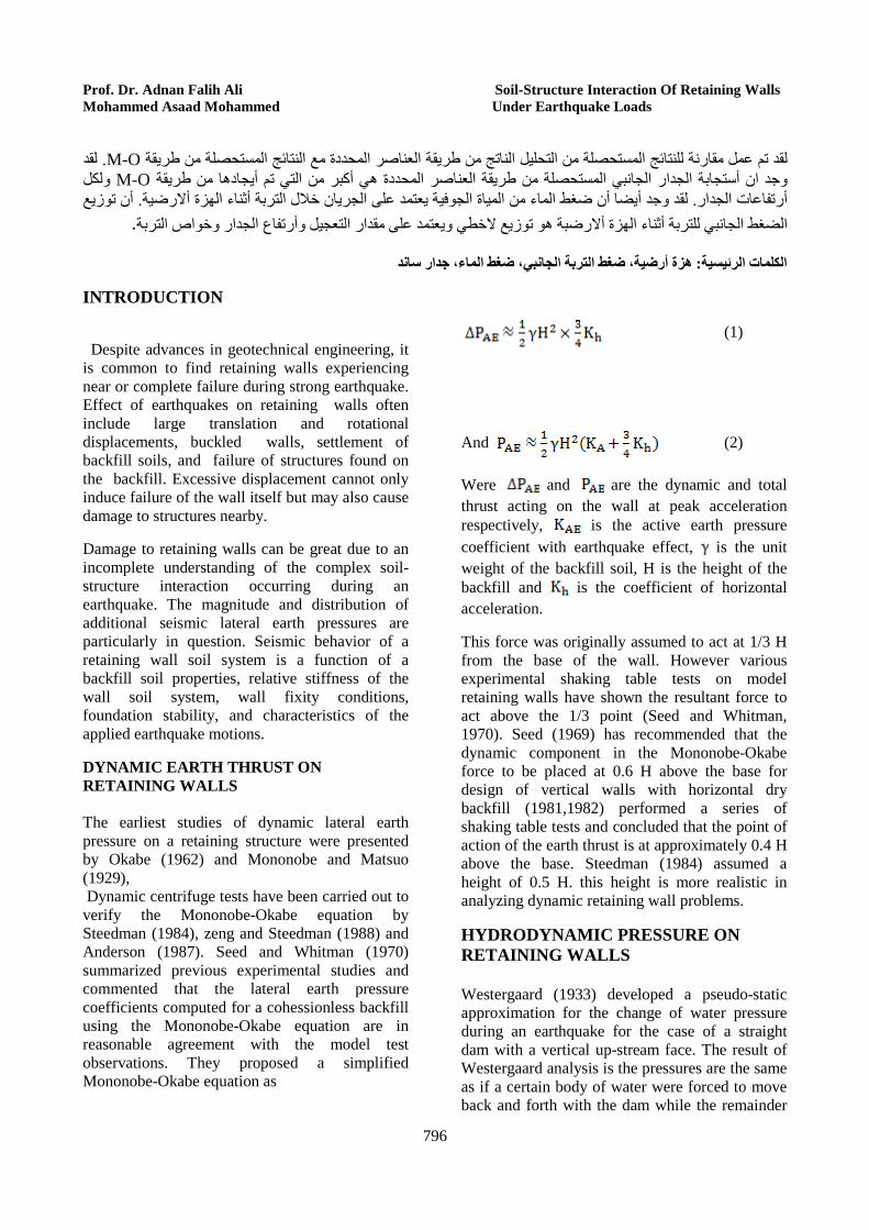
DYNAMIC EARTH THRUST ON RETAINING WALLS The earliest studies of dynamic lateral earth pressure on a retaining structure were presented by Okabe (1962) and Mononobe and Matsuo (1929), Dynamic centrifuge tests have been carried out to verify the Mononobe-Okabe equation by Steedman (1984), zeng and Steedman (1988) and Anderson (1987). Seed and Whitman (1970) summarized previous experimental studies and commented that the lateral earth pressure coefficients computed for a cohessionless backfill using the Mononobe-Okabe equation are in reasonable agreement with the model test observations. They proposed a simplified Mononobe-Okabe equation as
(1)
And (2)
Were and are the dynamic and total thrust acting on the wall at peak acceleration respectively, is the active earth pressure coefficient with earthquake effect, is the unit weight of the backfill soil, H is the height of the backfill and is the coefficient of horizontal acceleration.
This force was originally assumed to act at 1/3 H from the base of the wall. However various experimental shaking table tests on model retaining walls have shown the resultant force to act above the 1/3 point (Seed and Whitman, 1970). Seed (1969) has recommended that the dynamic component in the Mononobe-Okabe force to be placed at 0.6 H above the base for design of vertical walls with horizontal dry backfill (1981,1982) performed a series of shaking table tests and concluded that the point of action of the earth thrust is at approximately 0.4 H above the base. Steedman (1984) assumed a height of 0.5 H. this height is more realistic in analyzing dynamic retaining wall problems.
HYDRODYNAMIC PRESSURE ON RETAINING WALLS Westergaard (1933) developed a pseudo-static approximation for the change of water pressure during an earthquake for the case of a straight dam with a vertical up-stream face. The result of Westergaard analysis is the pressures are the same as if a certain body of water were forced to move back and forth with the dam while the remainder
Journal of Engineering Volume 19 July 2013 Number 7
797
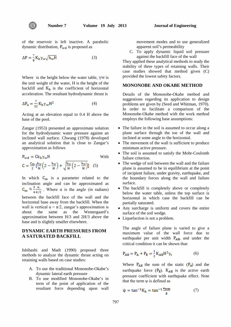
of the reservoir is left inactive. A parabolic dynamic distribution, is proposed as
(3)
Where is the height below the water table, is the unit weight of the water, H is the height of the backfill and is the coefficient of horizontal acceleration. The resultant hydrodynamic thrust is
(4)
Acting at an elevation equal to 0.4 H above the base of the pool.
Zangar (1953) presented an approximate solution for the hydrodynamic water pressure against an inclined wall surface. Chwang (1978) developed an analytical solution that is close to Zangar’s approximation as follows
With
(5)
In which is a parameter related to the inclination angle and can be approximated as
. Where α is the angle (in radians)
between the backfill face of the wall and the horizontal base away from the backfill. When the wall is vertical α = π/2, zangar’s approximation is about the same as the Westergaard’s approximation between H/3 and 2H/3 above the base and is slightly smaller elsewhere.
DYNAMIC EARTH PRESSURES FROM A SATURATED BACKFILL
Ishibashi and Madi (1990) proposed three methods to analyze the dynamic thrust acting on retaining walls based on case studies:
A. To use the traditional Mononobe-Okabe’s dynamic lateral earth pressure
B. To use modified Mononobe-Okabe’s in term of the point of application of the resultant force depending upon wall
movement modes and to use generalized apparent soil’s permeability
C. To apply dynamic liquid soil pressure against the backfill face of the wall
They applied these analytical methods to study the stability of three types of retaining walls. Their case studies showed that method given (C) provided the lowest safety factors.
MONONOBE AND OKABE METHOD
Details of the Mononobe-Okabe method and suggestions regarding its application to design problems are given by (Seed and Whitman, 1970). In order to facilitate a comparison of the Mononobe-Okabe method with the work method employs the following base assumptions:
• The failure in the soil is assumed to occur along a plane surface through the toe of the wall and inclined at some angle to the horizontal.
• The movement of the wall is sufficient to produce minimum active pressure.
• The soil is assumed to satisfy the Mohr-Coulomb failure criterion.
• The wedge of soil between the wall and the failure plane is assumed to be in equilibrium at the point of incipient failure, under gravity, earthquake, and the boundary forces along the wall and failure surface.
• The backfill is completely above or completely below the water table, unless the top surface is horizontal in which case the backfill can be partially saturated.
• Any surcharge is uniform and covers the entire surface of the soil wedge.
• Liquefaction is not a problem.
The angle of failure plane is varied to give a maximum value of the wall force due to earthquake per unit width , and under the critical condition it can be shown that:
(6)
Where the sum of the static ( ) and the earthquake force ( ). is the active earth pressure coefficient with earthquake effect. Note that the term ψ is defined as
(7)
Prof. Dr. Adnan Falih Ali Soil-Structure Interaction Of Retaining Walls Mohammed Asaad Mohammed Under Earthquake Loads
798
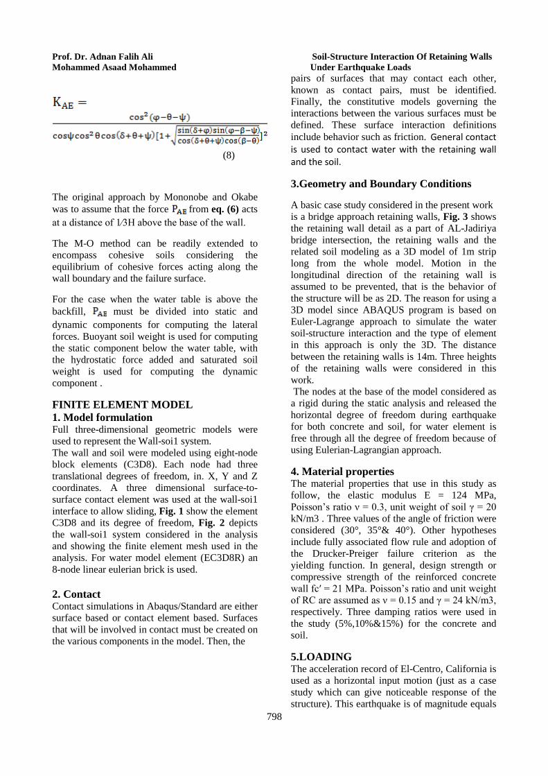
(8)
The original approach by Mononobe and Okabe was to assume that the force from eq. (6) acts at a distance of 1⁄3H above the base of the wall.
The M-O method can be readily extended to encompass cohesive soils considering the equilibrium of cohesive forces acting along the wall boundary and the failure surface.
For the case when the water table is above the backfill, must be divided into static and dynamic components for computing the lateral forces. Buoyant soil weight is used for computing the static component below the water table, with the hydrostatic force added and saturated soil weight is used for computing the dynamic component .
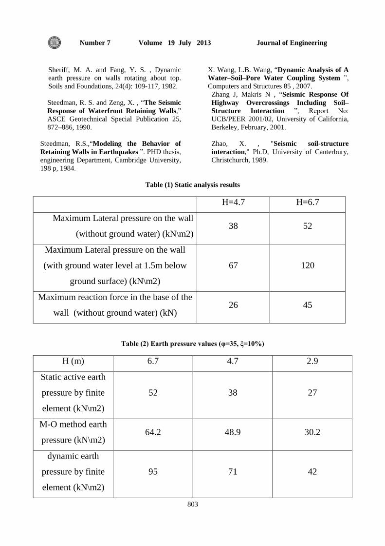
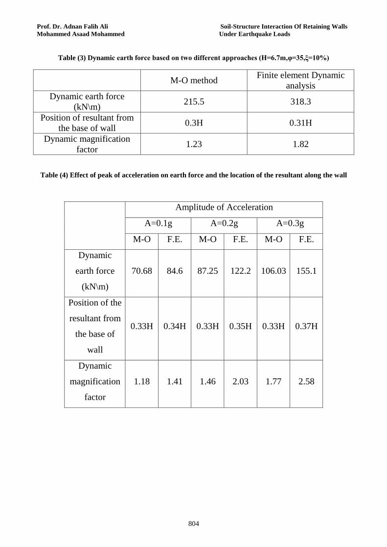
FINITE ELEMENT MODEL 1. Model formulation Full three-dimensional geometric models were used to represent the Wall-soi1 system. The wall and soil were modeled using eight-node block elements (C3D8). Each node had three translational degrees of freedom, in. X, Y and Z coordinates. A three dimensional surface-to-surface contact element was used at the wall-soi1 interface to allow sliding, Fig. 1 show the element C3D8 and its degree of freedom, Fig. 2 depicts the wall-soi1 system considered in the analysis and showing the finite element mesh used in the analysis. For water model element (EC3D8R) an 8-node linear eulerian brick is used. 2. Contact Contact simulations in Abaqus/Standard are either surface based or contact element based. Surfaces that will be involved in contact must be created on the various components in the model. Then, the
pairs of surfaces that may contact each other, known as contact pairs, must be identified. Finally, the constitutive models governing the interactions between the various surfaces must be defined. These surface interaction definitions include behavior such as friction. General contact is used to contact water with the retaining wall and the soil.
3.Geometry and Boundary Conditions
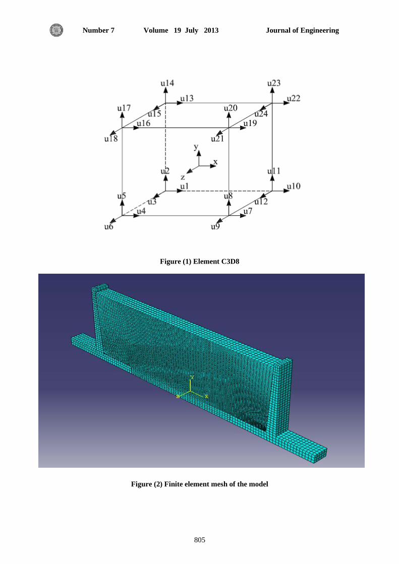
A basic case study considered in the present work is a bridge approach retaining walls, Fig. 3 shows the retaining wall detail as a part of AL-Jadiriya bridge intersection, the retaining walls and the related soil modeling as a 3D model of 1m strip long from the whole model. Motion in the longitudinal direction of the retaining wall is assumed to be prevented, that is the behavior of the structure will be as 2D. The reason for using a 3D model since ABAQUS program is based on Euler-Lagrange approach to simulate the water soil-structure interaction and the type of element in this approach is only the 3D. The distance between the retaining walls is 14m. Three heights of the retaining walls were considered in this work. The nodes at the base of the model considered as a rigid during the static analysis and released the horizontal degree of freedom during earthquake for both concrete and soil, for water element is free through all the degree of freedom because of using Eulerian-Lagrangian approach.
4. Material properties The material properties that use in this study as follow, the elastic modulus E = 124 MPa, Poisson’s ratio ν = 0.3, unit weight of soil γ = 20 kN/m3 . Three values of the angle of friction were considered (30°, 35°& 40°). Other hypotheses include fully associated flow rule and adoption of the Drucker-Preiger failure criterion as the yielding function. In general, design strength or compressive strength of the reinforced concrete wall fc′ = 21 MPa. Poisson’s ratio and unit weight of RC are assumed as ν = 0.15 and γ = 24 kN/m3, respectively. Three damping ratios were used in the study (5%,10%&15%) for the concrete and soil.
5.LOADING The acceleration record of El-Centro, California is used as a horizontal input motion (just as a case study which can give noticeable response of the structure). This earthquake is of magnitude equals
Journal of Engineering Volume 19 July 2013 Number 7
799
to 6.7 and a maximum acceleration of 0.35g which hit on may, 18, 1940. NUMERICAL RESULTS
1. Static Analysis
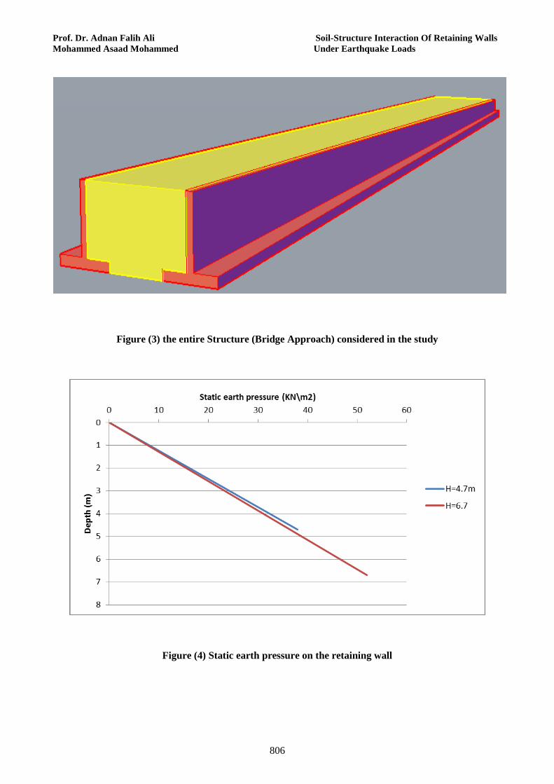
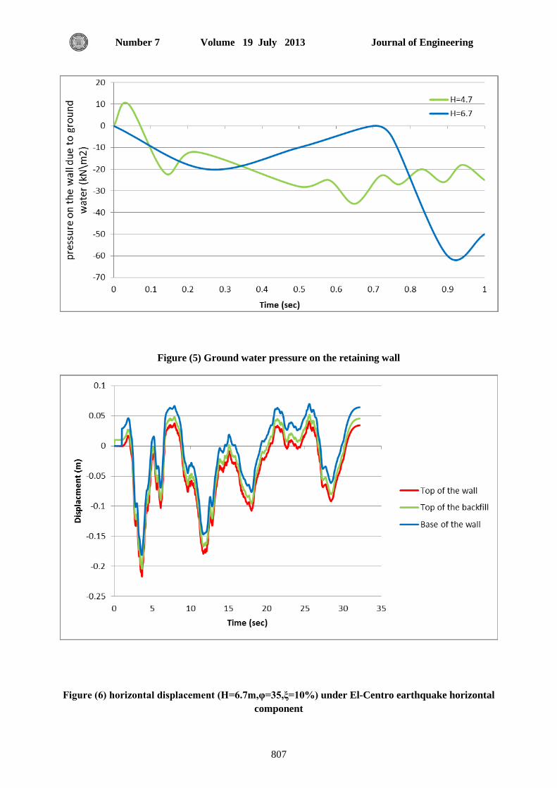
The first analysis was a static case study with two phases, namely without ground water and with the ground water, for two cases of wall heights as shown in Table 1. The static earth pressures are shown in Fig. 4 in the static analysis, the earth pressure is linear along the depth of the retaining wall, The ground water pressure on the retaining wall is shown in Fig. 5. To obtain the water pressure on the retaining wall using ABAQUS, the explicit analysis was used with smooth step to apply the load on the structure with one second time period so the behavior of the structure under this analysis is the same under static analysis such that one can notice the difference between the water pressure on the retaining walls in the figure.. It should be noted that the ground water level considered in the analysis is 1.5 m below the ground surface.
2. Dynamic Analysis
The second part of the study includes analysis of the retaining wall system of the bridge approach when acted upon by the earthquake base excitation. Several nodel point displacement were considered in the analysis, these are : horizontal displacement at the top backfill surface at midspan of the approach, horizontal displacement at top of the concrete retaining wall and at the base Fig. 6. It can be noticed that the overall motion of the wall-soil system is in phase, that is, relative damping is insignificant, however, the peak wall response is found to be different from that of the soil by almost 30% which highlights the effect of relative stiffness of the wall and the soil. Moreover the displacement at top of the wall is found to be larger than that of the base by about 50% at time of maximum response. Such a tendency is encountered since the wall is a cantilever free at the top and fixed at the base as compared to the base which is almost fixed. The negative sign mean the movement of the left wall to the left (active).
Analysis are also carried out for other cases of retaining wall heights (H=4.7) and (H=2.9). For
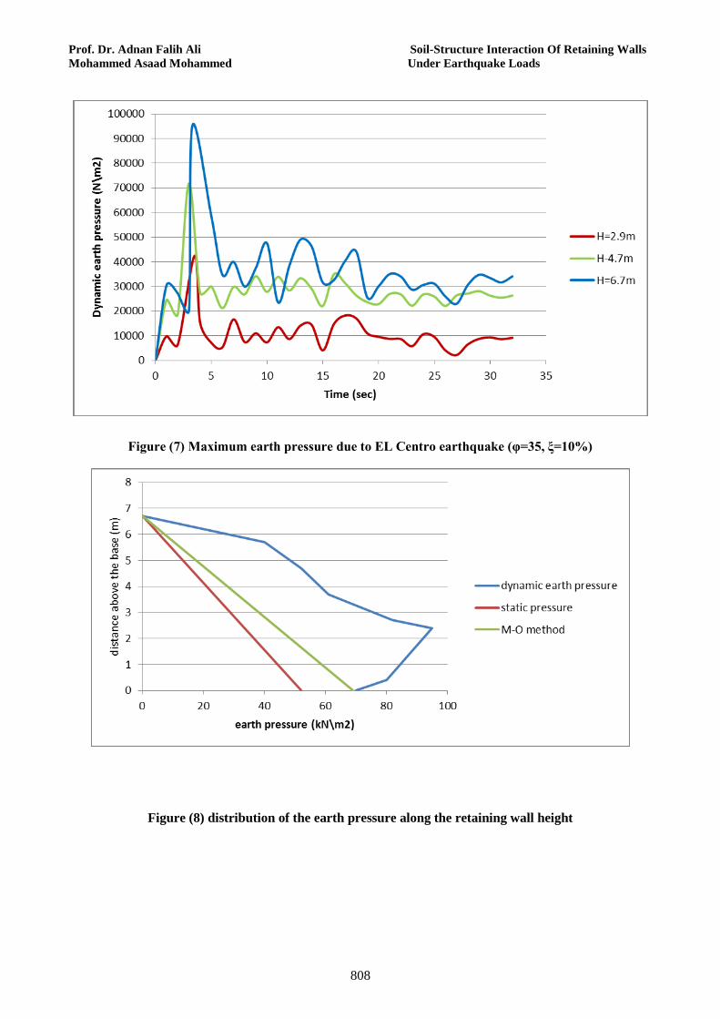
such cases, in addition to the case where the wall height H=6.7m, the maximum earth pressure on the bottom of the retaining walls were evaluated at different times due to EL-Centro earthquake base excitation of. Results are given in Fig. 7 for wall heights (H=6.7),(4.7) and (2.9) respectively.
A comparison of the maximum earth pressure acting at the retaining walls is presented in Table 2, for the static case and the dynamic case when evaluated using the M-O method and using time-domain analysis. As expected, it can be seen that the dynamic earth pressures are found to be larger than the static pressures for all cases of wall heights. Moreover, the dynamic earth pressure as obtained in the time-domain analysis are larger than these obtained using the M-O method, (angle of friction=35 and damping ratio=10%). It is also seen that the peak dynamic pressure was found to occur at different times, especially for the case of a wall of 6.7m height which is considered as relatively flexible as compared the relatively rigid 2.9m wall. The distribution of earth pressure along the depth of the retaining wall (static and dynamic using time domain analysis and M-O method) are presented in Fig. 8.
A comparison between the FE analysis results and those results obtained using M-O method is presented in Table 3. It was found that the position of the resultant of the dynamic pressure acting on the wall are approximately the same; however the magnitude of the maximum earth force as obtained using the FE method is almost 48% larger than that obtained by the M-O method. Hence the dynamic magnification factor (the maximum dynamic force divided by the maximum static force is (1.23) in case of the M-O method while it was (1.82) when using the FE method. The time-domain analysis using F.E. normally results in a more précis evaluation of the soil-structure interaction and hence behavior.
3. Parametric Study
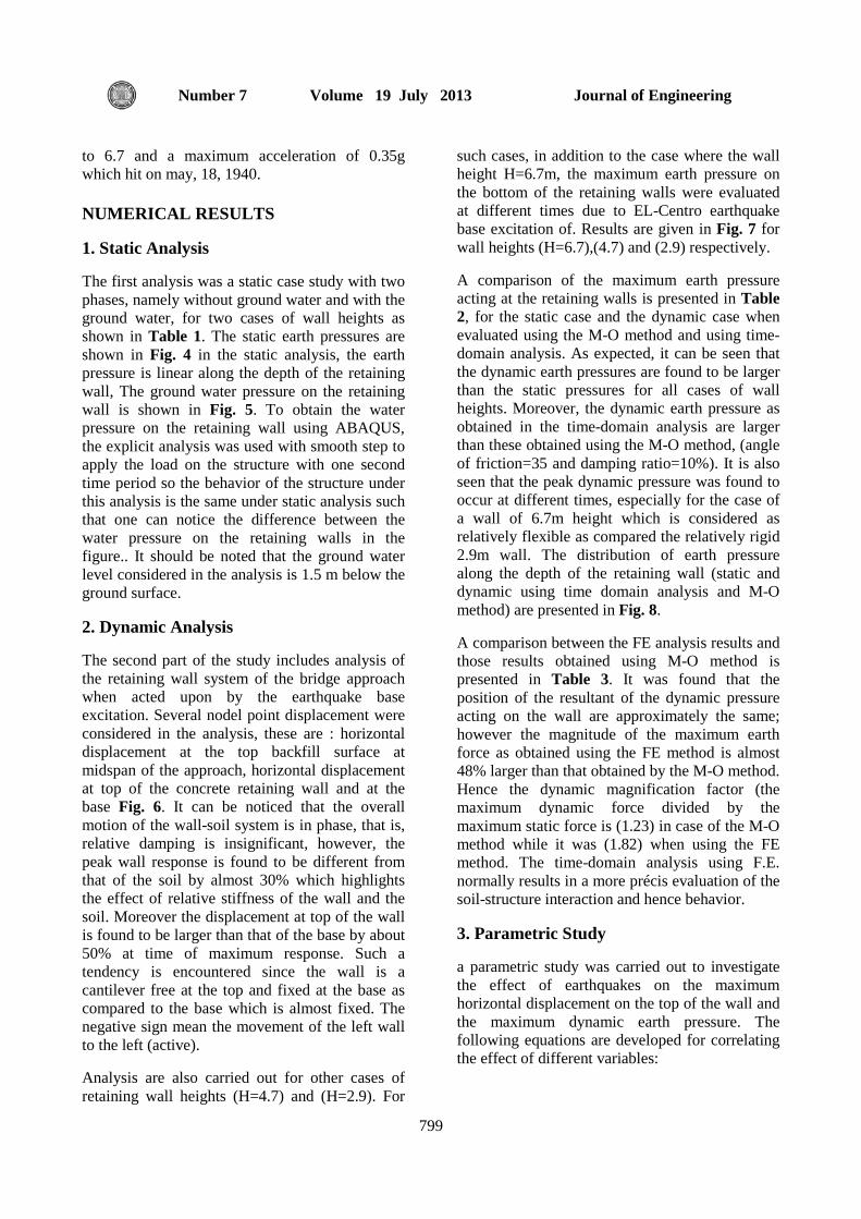
a parametric study was carried out to investigate the effect of earthquakes on the maximum horizontal displacement on the top of the wall and the maximum dynamic earth pressure. The following equations are developed for correlating the effect of different variables:
Prof. Dr. Adnan Falih Ali Soil-Structure Interaction Of Retaining Walls Mohammed Asaad Mohammed Under Earthquake Loads
800
(9)
(10)
Where:
maximum horizontal displacement at the top of wall (m)
H height of wall
ϕ angle of friction of the soil
ξ damping ratio
A peak acceleration in the ground motion (as ratio of g)
dynamic earth pressure (kN\m2)
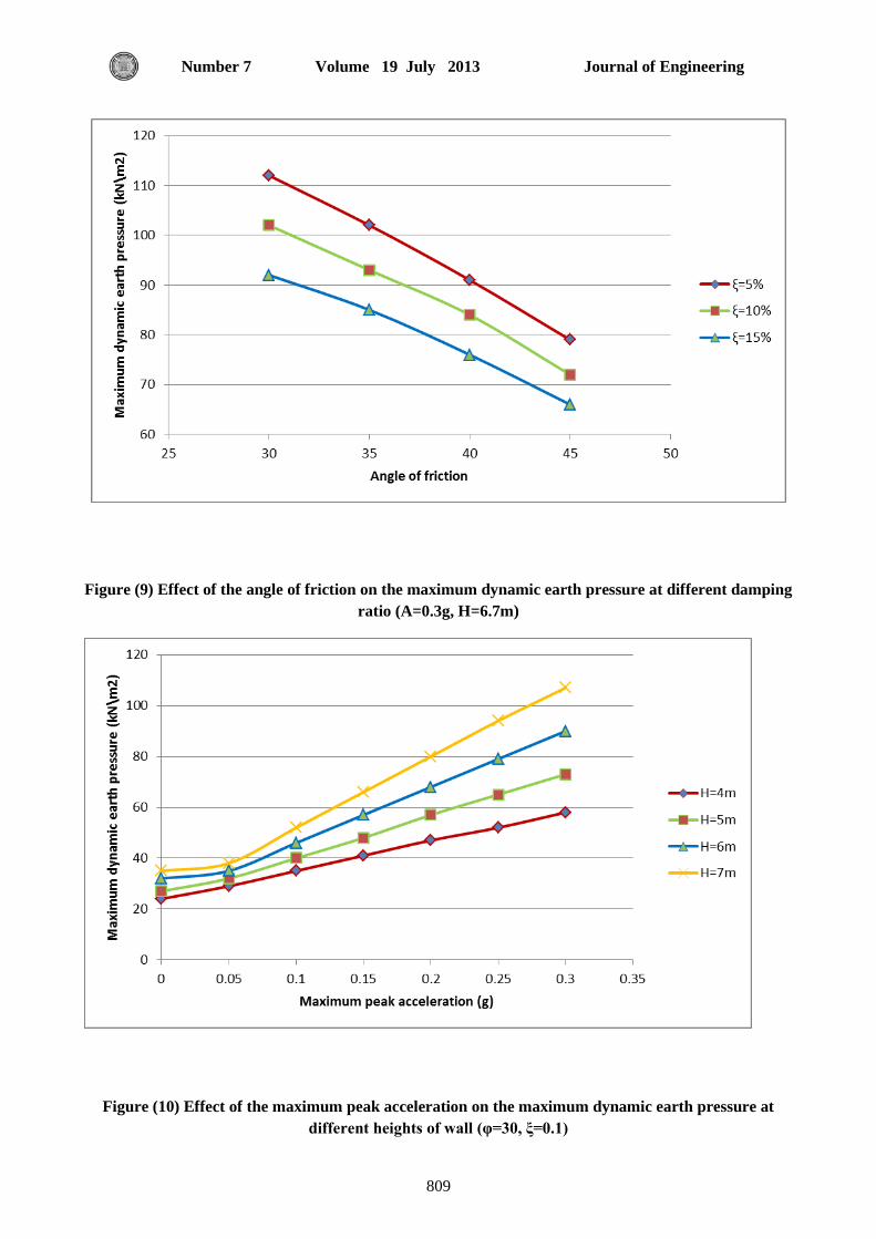
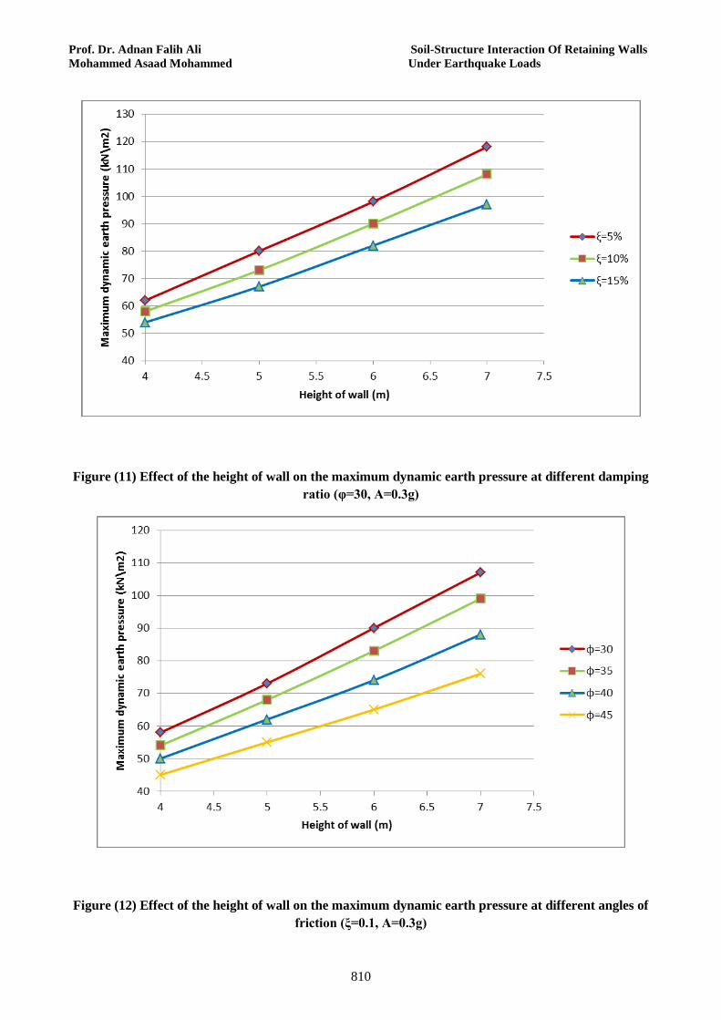
Figures from Fig. 9 to Fig. 12 show the effect of wall height, angle of the friction, damping ratio and the maximum peak acceleration on the maximum earth pressure. Solid lines in the figures represent the values calculated from eq. (10). The time history of horizontal displacement at the top of the wall and the dynamic earth force and the location of the resultant are summarized in Table 4 for the cases of wall system of 4.7m height. It is clear that the dynamic earth pressure increases with the increase in the height of wall, with the decrease in angle of internal friction, decrease in damping ratio and with the increase in the maximum peak acceleration of the earthquake excitation.
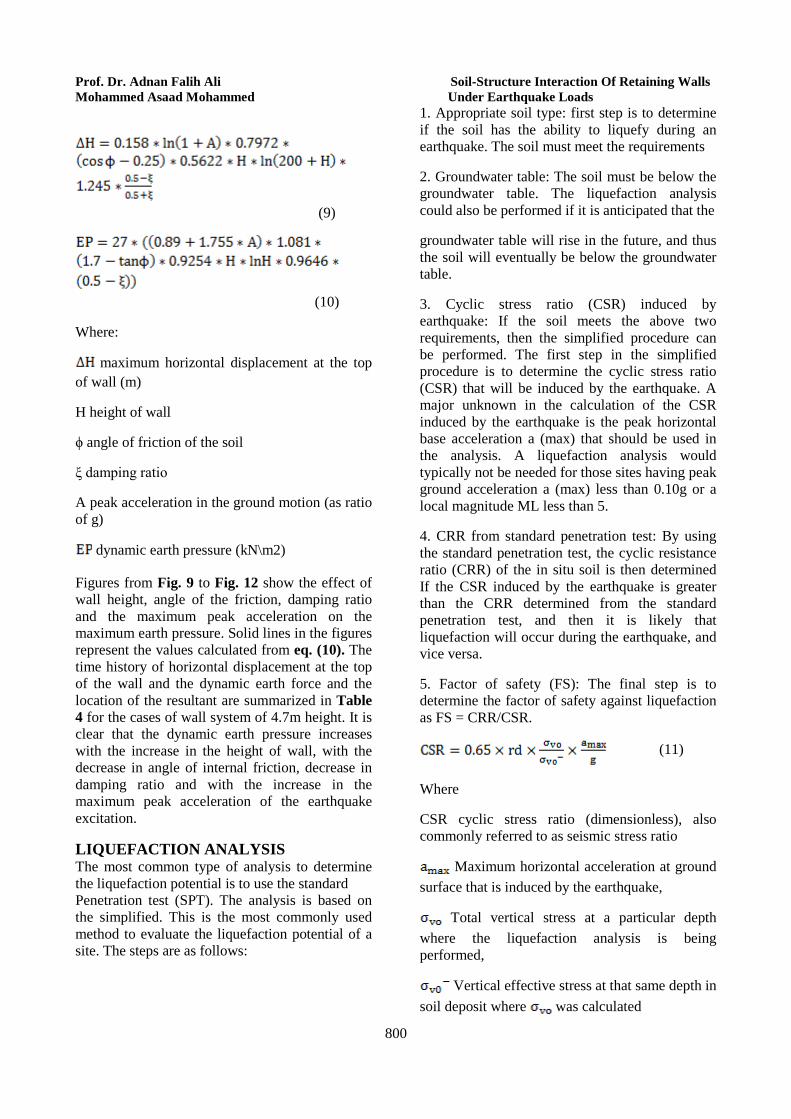
LIQUEFACTION ANALYSIS The most common type of analysis to determine the liquefaction potential is to use the standard Penetration test (SPT). The analysis is based on the simplified. This is the most commonly used method to evaluate the liquefaction potential of a site. The steps are as follows:
1. Appropriate soil type: first step is to determine if the soil has the ability to liquefy during an earthquake. The soil must meet the requirements
2. Groundwater table: The soil must be below the groundwater table. The liquefaction analysis could also be performed if it is anticipated that the
groundwater table will rise in the future, and thus the soil will eventually be below the groundwater table.
3. Cyclic stress ratio (CSR) induced by earthquake: If the soil meets the above two requirements, then the simplified procedure can be performed. The first step in the simplified procedure is to determine the cyclic stress ratio (CSR) that will be induced by the earthquake. A major unknown in the calculation of the CSR induced by the earthquake is the peak horizontal base acceleration a (max) that should be used in the analysis. A liquefaction analysis would typically not be needed for those sites having peak ground acceleration a (max) less than 0.10g or a local magnitude ML less than 5.
4. CRR from standard penetration test: By using the standard penetration test, the cyclic resistance ratio (CRR) of the in situ soil is then determined If the CSR induced by the earthquake is greater than the CRR determined from the standard penetration test, and then it is likely that liquefaction will occur during the earthquake, and vice versa.
5. Factor of safety (FS): The final step is to determine the factor of safety against liquefaction as FS = CRR/CSR.
(11)
Where
CSR cyclic stress ratio (dimensionless), also commonly referred to as seismic stress ratio
Maximum horizontal acceleration at ground surface that is induced by the earthquake,
Total vertical stress at a particular depth where the liquefaction analysis is being performed,
Vertical effective stress at that same depth in soil deposit where was calculated
Journal of Engineering Volume 19 July 2013 Number 7
801
g acceleration of gravity
rd depth reduction factor, also known as stress reduction coefficient
The final step in the liquefaction analysis is to calculate the factor of safety against liquefaction. If the cyclic stress ratio caused by the anticipated earthquake eq. (11) is greater than the cyclic resistance ratio of the in situ soil, then liquefaction could occur during the earthquake, and vice versa. The factor of safety against liquefaction (FS) is defined as follows:
(12)
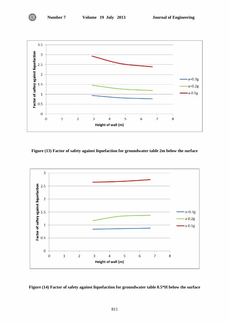
The higher the factor of safety, the more resistant the soil is to liquefaction. However, soil that has a factor of safety slightly greater than 1.0 may still liquefy during an earthquake. Fig. 13 and Fig. 14 show the Factor of safety against liquefaction for two cases of ground water.
CONCLUSIONS Based on the numerical case studies considered, the following conclusions are drown:
• The finite element analysis results in larger dynamic earth pressures acting on the walls than the M-O theory for all wall heights. The finite element method can precisely predict the actual relative motions of the wall-soil and hence resulting in larger magnitude of dynamic pressure on the wall. • The distribution of the dynamic earth pressure is
found to be nonlinear and depends on the earthquake ground acceleration. It is found to increase exponentially with the increase of ground acceleration. • Ground water pressure is primarily Influenced
by the water flow through the soil and by the height of the wall and the contact properties with the wall. • The value of factor of safety against liquefaction
decreases with increasing the peak acceleration of the earthquake and the ground water level below the soil surface.
REFERENCES “ABAQUS Analysis User’s Manual ˮ. Version 6.10. Providence (RI, USA): Dassault Systems Simulia Corp.; 2010.
“Peer (2000). Peer Strong Motion Database. California ˮ, http://peer.berkeley.edu/smcat/, University of California.
AL-Tae’e, A.Y., “Dynamic Response of Embankments and Dams by the Finite Element Method ˮ, M. Sc. Thesis, University of Baghdad, 2001. Andersen, G. A., Whitman, R. V. & Germaine, J. T. , “Seismic Response Of Rigid Tilting Walls, In Proceedings Of Centrifuge ˮ 91, Balkema, Rotterdam, The Netherlands, pp. 417–24, 1991. BAI De-gui , CHEN Guo-xing1 and WANG Zhi-hua, “Seismic Response Analysis Of The Large Bridge Pier Supported By Group Pile Foundation Considering the Effect of Wave And Current Action ˮ, The 14 World Conference on Earthquake Engineering October 12-17, 2008. Bathe, K-J., and Wilson, E. L. , “Numerical Methods in Finite Element Analysis,” Prentice-Hall, Englewood Cliffs, NJ, 1976. Bowles, J. E., “Foundation Analysis and Design”, McGraw-Hill, Inc. USA, 1977.
Carr, A. J. , "Soil-structure interaction." Advanced nonlinear seismic structural analysis notes, Pavia, 2008. Chambers, J. D. , "A distributed spring soil model for dynamic soil-strucutre intreaction analysis," University of Canterbury, Christchurch, 1998. Chen BF, Hung TK. “Dynamic Pressure of Water and Sediment On Rigid Dam. J Eng Mech ˮ, ASCE, 119 (7):1411–33, 1993. Chopra, A. K., “Dynamic of Structure”, Prentice-Hall, Inc. USA, 1995. Chwang, A. T., "Hydrodynamic pressures on sloping dams during earthquakes: Part 2, Exact Theory," J.Fluid Mech., 87, 342-348, 1978. Clough, R. W. and Penzien J., “Dynamics of Structures”, Third Edition Computers & Structures, Inc. New York, USA, 1976.
Prof. Dr. Adnan Falih Ali Soil-Structure Interaction Of Retaining Walls Mohammed Asaad Mohammed Under Earthquake Loads
802
Das, B. M. , “Principles of Soil Dynamics (PWS-KENT Publishing Company, Boston, Massachusetts), 1993.
Elewi, A.S., “Dynamic Stability of Retaining Walls ˮ, M. Sc. Thesis, University of Baghdad, 2003. Elgamal, A. W. Zeghal, M., and Parra, E. , “Liquefaction of reclaimed island in Kobe, Japan.” J. Geotech. Eng., 122~1!, 39–49, 1990. Finn, W. D. L. , “Dynamic Analyses In Geotechnical Engineering ˮ, in J. L. Von Thun (ed.), Earthquake Engineering and Soil Dynamics II—Recent Advances in Ground-Motion Evaluation, Geotechnical Special Publication 20, ASCE, pp. 523–91, 1988. Goel, R. K. and Chopra, A. K., “Period Formulas for Moment Resisting Frame Buildings, Journal of Structural Engineering", ASCE, 123(11), 1454-1461, 1997. H. Matsuo, and S. Ohara, “Lateral earth pressure and stability of quay walls during earthquakes”, In: Proc. of 2nd World Conference on Earthquake Engineering, Tokyo, 1960. Jawad Arefi , “Effects of Soil-Structure Interaction on the Seismic Response of Existing R.C. Frame Buildings”, 2008. Jing-Wen Chen, Nien-Hua Liu, and Jiun-Yaw Liou, “ Effects of Interface Properties On Horizontal Backfill Deformation Around Wall ˮ, Journal of GeoEngineering, Vol. 2, No. 1, pp. 13-18, 2007. Kim, S., and Stewart, J. P. , "Kinematic soil-structure interaction from strong motion recordings." Journal of Geotechnical & Geo environmental Engineering, ASCE, 129, 323-335, 2003. Kramer, S.L. ,“Geotechnical Earthquake Engineering, Prentice Hall”, 1996. M. Sherif, I. Ishibashi, and C. D. Lee, “Earth pressures against rigid retaining walls”, Journal of Geotechnical Engineering, ASCE, vol.108, (GT5), pp. 679-695, 1982.
McCallen, D.B. and Romstad, K.M. “Dynamic analyses of a skewed short-span, box-girder overpass. Earthquake Spectra". Vol. 10, No. 4: 729-755, 1994.
Mononobe, N. and Matsuo, H , “On The Determination of Earth Pressures during Earthquakes ˮ. Proceedings of world engineering congress, vol. 9, pp 177-185, 1929. Okabe, S. , “General Theory of Earth Pressure ˮ. Journal of Japanese Society of Civil Engineer, vol. 2, 1962. Okamura, M. and Matsuo, O , “A Displacement Prediction Method for Retaining Walls under Seismic Loading ˮ. Soil and Foundations 42:1, 131-138, 2002. Prakash, S. and Basavanna, B.M., “ Earth Pressure Distribution Behind Retaining Walls During Earthquakes ˮ, Proceeding Fourth World Conference on Earthquake Engineering, Santiago, Chile, 1969. R.J. Bathurst, S. Zarnani and A. Gaskin, “Shaking Table Testing of Geofoam Seismic Buffers,” Soil Dynamic Earthquake Eng., vol. 4, pp. 324-332, 2007. Richards, R., Huang, C., and Fishman, K.L., “Seismic Earth Pressure on Retaining Structures”, J. of Geotech. And Geoenvir. Eng., ASCE, 125(9), 771-778, 1999. Russell A. Green. “ Response And Modeling Of Cantilever Retaining Walls Subjected To Seismic Motions ˮ, Computer-Aided Civil and Infrastructure Engineering 309–322, 2008. Seed, H. B. and Whitman, R. V. “Design of earth retaining structures for dynamic loads”. In Proceedings, ASCE Specialty Conference on Lateral Stresses in the Ground and Design of Earth Retaining Structures, pp. 103-147, 1970. Seed, H.B., and Idriss, I.M., “Simplified procedure for evaluating soil”, 1971.
Journal of Engineering Volume 19 July 2013 Number 7
803
Sheriff, M. A. and Fang, Y. S. , Dynamic earth pressure on walls rotating about top. Soils and Foundations, 24(4): 109-117, 1982. Steedman, R. S. and Zeng, X. , “The Seismic Response of Waterfront Retaining Walls,” ASCE Geotechnical Special Publication 25, 872–886, 1990.
Steedman, R.S.,“Modeling the Behavior of Retaining Walls in Earthquakes ˮ. PHD thesis, engineering Department, Cambridge University, 198 p, 1984.
X. Wang, L.B. Wang, “Dynamic Analysis of A Water–Soil–Pore Water Coupling System ˮ, Computers and Structures 85 , 2007.
Zhang J, Makris N , “Seismic Response Of Highway Overcrossings Including Soil–Structure Interaction ˮ, Report No: UCB/PEER 2001/02, University of California, Berkeley, February, 2001. Zhao, X. , "Seismic soil-structure interaction," Ph.D, University of Canterbury, Christchurch, 1989.
Table (1) Static analysis results
H=4.7 H=6.7
Maximum Lateral pressure on the wall
(without ground water) (kN\m2) 38 52
Maximum Lateral pressure on the wall
(with ground water level at 1.5m below
ground surface) (kN\m2)
67 120
Maximum reaction force in the base of the
wall (without ground water) (kN) 26 45
Table (2) Earth pressure values (φ=35, ξ=10%)
H (m) 6.7 4.7 2.9
Static active earth
pressure by finite
element (kN\m2)
52 38 27
M-O method earth
pressure (kN\m2) 64.2 48.9 30.2
dynamic earth
pressure by finite
element (kN\m2)
95 71 42
Prof. Dr. Adnan Falih Ali Soil-Structure Interaction Of Retaining Walls Mohammed Asaad Mohammed Under Earthquake Loads
804
Table (3) Dynamic earth force based on two different approaches (H=6.7m,φ=35,ξ=10%)
M-O method Finite element Dynamic
analysis Dynamic earth force
(kN\m) 215.5 318.3
Position of resultant from the base of wall 0.3H 0.31H
Dynamic magnification factor 1.23 1.82
Table (4) Effect of peak of acceleration on earth force and the location of the resultant along the wall
Amplitude of Acceleration
A=0.1g A=0.2g A=0.3g
M-O F.E. M-O F.E. M-O F.E.
Dynamic
earth force
(kN\m)
70.68 84.6 87.25 122.2 106.03 155.1
Position of the
resultant from
the base of
wall
0.33H 0.34H 0.33H 0.35H 0.33H 0.37H
Dynamic
magnification
factor
1.18 1.41 1.46 2.03 1.77 2.58
Journal of Engineering Volume 19 July 2013 Number 7
805
Figure (1) Element C3D8
Figure (2) Finite element mesh of the model
Prof. Dr. Adnan Falih Ali Soil-Structure Interaction Of Retaining Walls Mohammed Asaad Mohammed Under Earthquake Loads
806
Figure (3) the entire Structure (Bridge Approach) considered in the study
Figure (4) Static earth pressure on the retaining wall
Journal of Engineering Volume 19 July 2013 Number 7
807
Figure (5) Ground water pressure on the retaining wall
Figure (6) horizontal displacement (H=6.7m,φ=35,ξ=10%) under El-Centro earthquake horizontal component
Prof. Dr. Adnan Falih Ali Soil-Structure Interaction Of Retaining Walls Mohammed Asaad Mohammed Under Earthquake Loads
808
Figure (7) Maximum earth pressure due to EL Centro earthquake (φ=35, ξ=10%)
Figure (8) distribution of the earth pressure along the retaining wall height
Journal of Engineering Volume 19 July 2013 Number 7
809
Figure (9) Effect of the angle of friction on the maximum dynamic earth pressure at different damping ratio (A=0.3g, H=6.7m)
Figure (10) Effect of the maximum peak acceleration on the maximum dynamic earth pressure at different heights of wall (φ=30, ξ=0.1)
Prof. Dr. Adnan Falih Ali Soil-Structure Interaction Of Retaining Walls Mohammed Asaad Mohammed Under Earthquake Loads
810
Figure (11) Effect of the height of wall on the maximum dynamic earth pressure at different damping ratio (φ=30, A=0.3g)
Figure (12) Effect of the height of wall on the maximum dynamic earth pressure at different angles of friction (ξ=0.1, A=0.3g)
Journal of Engineering Volume 19 July 2013 Number 7
811
Figure (13) Factor of safety against liquefaction for groundwater table 2m below the surface
Figure (14) Factor of safety against liquefaction for groundwater table 0.5*H below the surface