Energy Research and Development Division FINAL PROJECT REPORT SOLAR‐ ASSISTED GAS HOT WATER HEATING SYSTEMS FOR SMALL FOOD PROCESSORS Prepared for: California Energy Commission Prepared by: Gas Technology Institute DECEMBER 2013 CEC ‐ 500 ‐ 2014 ‐ 071
Transcript
Energy Research and Development Div is ion FINAL PROJECT REPORT
SOLAR‐ASSISTED GAS HOT WATER HEATING SYSTEMS FOR SMALL FOOD PROCESSORS
Prepared for: California Energy Commission Prepared by: Gas Technology Institute
DECEMBER 2013CEC ‐500 ‐2014 ‐071
PREPARED BY: Primary Author(s): David Cygan Hillary Vadnal Joseph Pondo Gas Technology Institute 1700 S. Mount Prospect Rd. Des Plaines, Illinois 60018 http://www.gastechnology.org Contract Number: PIR-09-008 Prepared for: California Energy Commission Michael Lozano Contract Manager Virginia Lew Office Manager Energy Efficiency Research Office Laurie ten Hope Deputy Director ENERGY RESEARCH AND DEVELOPMENT DIVISION Robert P. Oglesby Executive Director
DISCLAIMER This report was prepared as the result of work sponsored by the California Energy Commission. It does not necessarily represent the views of the Energy Commission, its employees or the State of California. The Energy Commission, the State of California, its employees, contractors and subcontractors make no warranty, express or implied, and assume no legal liability for the information in this report; nor does any party represent that the uses of this information will not infringe upon privately owned rights. This report has not been approved or disapproved by the California Energy Commission nor has the California Energy Commission passed upon the accuracy or adequacy of the information in this report.
ACKNOWLEDGEMENTS
This report was submitted under grant number PIR‐09‐008 from the California Energy Commission. Thanks to the Utilization Technology Development NP, Southern California Gas Company, Solar Usage Now, and Knecht’s Plumbing & Heating, Inc. for financial, engineering, and technical support of this project and to the host site Courtside Cellars.
i
PREFACE
The California Energy Commission Energy Research and Development Division supports public interest energy research and development that will help improve the quality of life in California by bringing environmentally safe, affordable, and reliable energy services and products to the marketplace.
The Energy Research and Development Division conducts public interest research, development, and demonstration (RD&D) projects to benefit California.
The Energy Research and Development Division strives to conduct the most promising public interest energy research by partnering with RD&D entities, including individuals, businesses, utilities, and public or private research institutions.
Energy Research and Development Division funding efforts are focused on the following RD&D program areas:
• Buildings End‐Use Energy Efficiency
• Energy Innovations Small Grants
• Energy‐Related Environmental Research
• Energy Systems Integration
• Environmentally Preferred Advanced Generation
• Industrial/Agricultural/Water End‐Use Energy Efficiency
• Renewable Energy Technologies
• Transportation
Solar-Assisted Gas Hot Water Heating Systems for Small Food Processors is the final report for the Solar‐Assisted Gas Hot Water Heating Systems for Small Food Processors project PIR‐09‐008 conducted by Gas Technology Institute. The information from this project contributes to Energy Research and Development Division’s Industrial/Agricultural/Water End‐Use Energy Efficiency Program.
For more information about the Energy Research and Development Division, please visit the Energy Commission’s website at www.energy.ca.gov/research/ or contact the Energy Commission at 916‐327‐1551.
The Gas Technology Institute (GTI), along with its partners Solar Usage Now and Knecht’s Plumbing & Heating, Inc., demonstrated an advanced solar‐assisted gas hot water heating system for advanced solar‐assisted hot water generation at Courtside Cellars, San Miguel, California. This system reduces the material, manufacturing, and installation cost of solar‐assisted water heating systems. The system is a combination of an atmospheric storage tank, a highly efficient natural gas‐fired tankless water heater, and a highly efficient solar thermal collector. This system takes the most efficient technologies on the market and integrates them into an energy efficient package. The modular design of the hot water storage tank makes them ideal to be linked together to replace boilers used for large commercial applications such as breweries, soft drink production, hotels, schools and hospitals. GTI validated the ability of the system to achieve an energy cost savings of 40 percent and a corresponding reduction in greenhouse gases in small commercial agricultural businesses. This solar‐assisted gas hot water heating system makes advanced water heating implementation more attractive, mitigating greenhouse gas emissions, improving the competitiveness of California industry, and increasing the reliability of hot water at end‐user sites.
Keywords: renewables, solar, solar thermal, solar‐assisted, water heating, evacuated tube, tankless water heater, field test
Please use the following citation for this report:
Cygan, David, Hillary Vadnal and Joseph Pondo. (Gas Technology Institute). 2013. Solar‐Assisted Gas Hot Water Heating Systems for Small Food Processors. California Energy Commission. Publication number: CEC‐500‐2014‐071.
iii
TABLE OF CONTENTS
Acknowledgements ................................................................................................................................... i
PREFACE ................................................................................................................................................... ii
ABSTRACT .............................................................................................................................................. iii
TABLE OF CONTENTS ......................................................................................................................... iv
LIST OF FIGURES .................................................................................................................................... v
LIST OF TABLES ................................................................................................................................... vii
Table 3: Correlation Coefficient between Fuel Efficiency, Solar Radiation, Ambient Temperature, and Load .......................................................................................................................... 66
Table 4: Energy Balance for Courtside Cellars .................................................................................. 73
Table 6: Fifteen Year Lifecycle Costs ................................................................................................... 78
EXECUTIVE SUMMARY
Introduction The California wineries generate almost 90 percent of all wine produced in the United States. The industry consumes more than 400 GWh of electricity annually and is the second largest electricity consuming food industry in California after fruit and vegetable processing. Much of the electricity used in winemaking is for refrigeration for cooling and cold storage. Hot water is essential for sanitizing barrels, bottles and equipment, for maintaining tank temperature during red wine fermentation and yeast generation.
Energy and water costs continue to increase rapidly for wineries located in California, making energy and water efficiency improvement an essential part of the business. To reduce hot water consumption, California winemakers are implementing various efficiency measures. These measures include but are not limited to using treated wastewater for irrigation and landscaping, frost protection, fire protection, and dust abatement; high‐pressure spray nozzles for tank and barrel cleaning; and leak detection and repair. These measures have the added benefit of eliminating energy costs associated with pumping and heating the water that has been saved.
Project Gas Technology Institute (GTI) partnered with Solar Usage Now to design and demonstrate an advance solar‐assisted gas hot water heating system at Courtside Cellars, San Miguel, California. Together GTI and Solar Usage Now have addressed the commercial market identifying and resolving solar‐assisted water heating technologies and market issues to assist industry in the identification of a viable gas‐fired water heating option capable of meeting customer expectations for cost, safety, reliability, and performance. Knecht’s Plumbing & Heating, Inc. was instrumental in the installation of the system.
The design of a highly efficient and robust solar thermal system, “Equinox Heating System”, was completed, and permanently installed at the Courtside Cellars production facility. The system has operated continuously under actual commercial hot water load profiles for this production facility. An acquisition system collected data simultaneously to record the system variation.
The Equinox Heating System is a combination of an atmospheric storage tank, a highly efficient natural gas‐fired tankless water heater, and a very efficient solar thermal collector. This system takes the most efficient technologies on the market and integrates them into an energy efficient package. The system is very flexible and can operate under many temperature setting combinations depending on how the system is applied.
Installing enough capacity to replace both existing boilers was estimated to be larger than what was economically possible. It was determined to augment the existing boiler capacity with the Equinox Heating System. A year of monitoring has revealed the average daily load as 1.6 million Btu. The Equinox Heating System daily load ranged between 0.5 million Btu and 5.0 million Btu. An appropriately sized solar collector would be 128 meters2, or 45 collectors.
1
Overall, the Equinox Heating System performed extremely well; at peak conditions the fuel efficiency was more than 95 percent, generating more than 1,700 gallons of hot water daily. Compared to the standard baseline efficiency gas boiler, the system saved approximately 1190 therms of natural gas during the year of monitoring. This energy savings corresponds to a potential reduction of 17,500 lbs of greenhouse gas emissions per year.
The estimated payback period for the Equinox Heating System was 7.3 years, including incentives provided by state and federal governments. This payback period includes equipment and installation. As more installations occur, this payback is expected to improve as firms learn to install the system at lower costs. Addidionally, payback periods are dependent upon the solar fraction and available incentives. Solar‐assisted systems provide a non‐complex technology that is a financially viable alternative over traditional water heating systems. With incentives, the 15 year lifecycle cost is less than traditional water heating systems.
In reducing energy costs, boilers are the heart of the hot water generation system at larger wineries, and substantial efficiency improvements are feasible here (i.e. improved boiler maintenance, low emission burners, reduced excess air, reduce flue gas volume, etc.). Hot water storage is another factor to consider when so much hot water is used and needed on demand. Most large wineries have tanks with capacities ranging from 500 to 3,000 gallons. In smaller wineries, investments in equipment are kept low by purchasing readily available commercial hot water heaters, small boilers, and conventional storage tanks that are less than 199 gallons. At 200 gallons the storage tank must be an approved pressure vessel adding significantly to the initial cost.
Benefits The opportunity for substantial energy costs savings in smaller wineries comes at a higher purchase cost and longer payback. By reducing the purchase cost and increasing the potential savings, quicker paybacks can be realized. An improved solar‐assisted gas fired hot water system, such as the Equinox Heating System, may realize such a payback. A solar‐assisted gas fired hot water system uses solar energy to pre‐heat the boiler feedwater in a solar thermal collector. Until recently, solar‐assist has mainly been designed for residential applications or to heat pool water. However, for small wineries a solar‐assisted boiler may be a good alternative. The harvesting season sees a major part of the water use for cleaning (excluding year‐round operation of a bottling facility), and this is also a time with large availability of sunlight. A solar‐assisted boiler may reduce the costs of hot water supply between 40 to 80 percent, depending on the current hot water supply.
2
3
CHAPTER 1: Value of the Technology Today many Americans face higher energy prices, compounded by supply related fluctuations and even power outages. Small commercial businesses can be most affected by price fluctuation and power outages. Reducing the energy needs of these small businesses improves positive cash flow and provides benefit to the greater economy, the environment, and increases energy security. This can best be achieved through a combination of conservation and efficiency with small businesses. Small wineries, those producing 50,000 cases of wine per year or less, make‐up greater than 90 percent of the in the Unites States. Predominantly small family‐based operations, according to 2006 U.S. Census statistics, 78 percent of these wineries have has less than 20 employees. Improving their energy outlook provides direct benefit to the local economy.
Solar‐assisted water heating has evolved around the world in nations with tropical and temperate climates. These market transformations have been driven by high energy costs, unreliable infrastructure, incentives, and technological advancements. While the technology exists, it has only recent begun to make inroads in the U.S. markets. Research is needed to ensure that these systems are able to meet the price and performance U.S. commercial business require for an acceptable payback.
This program advances state‐of‐the‐art solar‐assisted gas water heating at California wineries. In small winery operations, where capital investment and cash flow is limited, technology transformation is slow without demonstrated proof of field performance. A dramatic increase in market penetration for solar‐assist water heating is possible and would benefit the California Food Processing Industry; however, the industry is wary regarding the performance of this technology. Validated installation methods that significantly reduce required equipment size and energy consumption will help these technologies gain the necessary recognition for significant market impact. GTI’s research and development team has joined forces with Solar Usage Now to develop an advanced solar‐assisted water heating system to meet the growing needs of the California wine industry.
1.1 Solar System Overview The solar‐assisted gas hot water heating system, Equinox Heating System, reduces the material, manufacturing, and installation costs of solar‐assisted natural gas water heating systems for small commercial, industrial, and agricultural applications (Figure 1). This highly efficient hot water delivery system is designed to meet the reliability and performance requirements for hot water found in California’s small to mid‐size wineries. The major components of the Equinox Heating System include an atmospheric storage tank, a highly efficient natural gas‐fired tankless water heater, and an efficient solar thermal collector. The design reduces and eliminates major components and associated costs, such as a second storage tank for solar, but affords maximum flexibility for installation and utility business considerations. Implementing a
4
high‐efficient drainback solar collector expands the market for solar water heating, particularly to areas where freeze protection is required.
Figure 1: Equinox Heating System
Solar Thermal Collector
Storage Tank
Tankless Water Heater
The Equinox Heating System is a pressure‐free and environmentally friendly solar installation. Water is the heat transfer fluid, thus eliminating the use of ethyl glycol as a heat transfer fluid as it is a listed hazardous substance in California, and the systems will not experience the issues of overheating associated with glycol fluid systems. The system is “active” and relies on pumps and controllers to circulate water, the heat transfer fluid, through the solar collectors. The collector is installed at a slope of ¼” per foot of collector, so when the pumps stop, the water will drainback to the tank, and not be left in the pipes to freeze and burst. This will expand the market for solar water heating, particularly to areas where freeze protection is required.
The Equinox Heating System was conceived in accordance with the latest thermal technology and water hygiene requirements. Fundamentally different from normal large volume hot water storage tanks, the storage tank water is filled once during commissioning, and is circulated between the tank and the solar collector. Internal to the tank, is a stainless steel corrugated heat exchanger which is immersed in the storage tank water where domestic hot water is indirectly heated. The coils carry the fresh water supply providing separation of the fresh water from the
5
water heated by the solar array and used for thermal storage ensuring that no germs or diseases can be born through the water.
The modular design of the hot water storage tank makes them ideal to be linked together to replace boilers used for large wineries, multi‐family housing, and commercial applications such as hotels, schools, hospitals, etc (Figure 2). This highly efficient hot water delivery system is designed to meet the reliability and performance needs of most residential/commercial applications throughout the U.S.
Figure 2: Modular Design for Commercial Hot Water Systems
DASHED LINES INDICATE 1" PIPING PROVIDED BY
INSTALLAER
6
The project partner, Solar Usage Now, is also a distributor for Solarhot USA, Califfei Solar, Rotex, Quietside, and Apricus solar products. Products are marketed, installed, and serviced by over 250 certified dealers and installers nationwide in both the residential and commercial
1.2 Atmospheric Storage Tank The hot water storage tank is a corrosion‐free plastic atmospheric tank, the inner and outer walls are impact resistant polypropylene, and the space in‐between is filled with high insulating foam (Figure 3). This design provides for very good heat insulation values and minimum surface losses. The circulation water for the solar collector held in the tank is used not stored, so there is never a chance for particles and sediments to settle in the tank. This means no germs or diseases can be born through the water. The storage tank water is filled once during commissioning and is circulated between the storage tank and the solar collectors. It is neither replaced nor consumed. The heat from the solar collectors is transferred to the storage tank and warms the storage tank water. Internal to the tank is a stainless steel corrugated heat exchanger which is immersed in the storage tank water where domestic hot water is indirectly heated. This ensures optimum inherent water‐hygienic properties since the water to be heated is ducted and heated through a stainless steel heat exchanger.
Any low flow sections or sections that are not heated properly on the hot water side are completely eliminated in the design. The commercial hot water is entirely contained in a piping system so that any deposits such as sediment and rust which can arise in large volume tanks are not produced. Water that is charged first is also the first to be removed. The water hygiene advantages of the atmospheric hot water storage tank are thus considerable. The storage tank is available in 80 and 132 gallon capacities.
Figure 3: Atmospheric Storage Tanks with Cut Away View
7
1.3 Tankless Water Heater The Noritz tankless water heater provides exceptional performance and efficiency coupled with the comfort of on demand hot water. Revolutionary heat exchangers provide an energy factor of 0.95. These efficiency levels are achieved by utilizing two heat exchangers, including a wet recuperative heat exchanger, manufactured from stainless steel. This heat exchanger condenses water from the combustion gases which is used to preheat the water. The tankless water heater is another key component in the system charging the storage tank water when no solar energy is available. The temperature of the gas‐fired tankless water heater is set at 180 °F for fast recovery of the tank temperature.
1.4 Solar Thermal Collector The Equinox Heating System used the Apricus solar collector (Model No. AP‐30). The collector is an array of 30 twin‐glass evacuated tubes, chosen for its reliability, performance, and low manufacturing cost. The tubes aligned in parallel and join into a common header where the heat transfer fluid (i.e. water) is transported. The evacuated tubes consist of two glass tubes made from extremely strong borosilicate glass. The outer tube is transparent, allowing light rays to pass through with minimal reflection while the inner tube is coated with a special selective coating which features excellent solar radiation absorption and minimal reflection properties (Figure 4). The top of the two tubes are fused together after the air contained in the space between the two layers of glass is removed. This ʺevacuationʺ of the gasses forms a vacuum and provides an insulating barrier inside the tube. The insulation properties are so good that while the inside of the tube may be ~300°F, the outer tube is cold to touch. In order to maintain the vacuum between the two glass layers, a barium getter is used. During manufacture of the evacuated tube, the getter is exposed to high‐temperatures which results in the bottom of the tube being coated with a pure layer of barium. This barium layer actively absorbs any out‐gasses from the tube during storage and operation, thus helping to maintain the vacuum. The barium layer also provides a clear visual indicator of the vacuum status. The silver colored barium layer will turn white if the vacuum is ever lost. This makes it easy to determine whether or not a tube is in good condition.
Each evacuated tube contains a heat pipe transporting the heat by conduction to the common header (Figure 5). The purpose for evacuation of the heat pipe is to alter the state of a small quantity of purified water and some special additives inside so that the mixture will boil at a lower temperature ~86 °F. When the heat pipe is heated above 86 °F, the water vaporizes. This vapor rapidly rises to the top of the heat pipe transferring heat to the thermal fluid (i.e. water) at the common header. As the heat is lost at the condenser, the vapor condenses to form a liquid and returns to the bottom of the heat pipe to once again repeat the process. The angle of mounting for the solar array depends upon the latitude at a given installation location. In a North or South orientation, the tubes can passively track heat from the sun all day. In an East or West orientation, they can track the sun all year round.
8
Figure 4: Close Up of the Evacuate Tube
Figure 5: Evacuated Tube with Heat Pipe Technology
9
1.5 Circulation System The circulation system is “active” and relies on pumps and controllers to circulate water, the heat transfer fluid, through the solar collectors returning to the storage tank to heat the tank water.
1.5.1 Controller The Equinox circulation system uses a Watts Controller (Figure 6). The controller measures temperatures at three locations in the system and activates water flow at the pump to the solar collector and tankless water heater at the optimum time. The three locations (T1, T2, and T3), shown in Figure 7, are:
1. T1: Return‐side of the solar array header; 2. T2: 54” from the top of the storage tank. This controls the
solar pump (P1 in Figure 7); and 3. T3: 33” from the top of the storage tank. This controls the
tankless water heater pump (P3 in Figure 7).
Figure 6: Watts Advanced Solar Controller
Figure 7: Location of Watts Controller Sensors: T1, T2, and T3
10
If T1 is 30 °F greater than T2, the solar pump “P1” will initiate. As water is pumped to the collector, heat will be absorbed at across the header, the temperature of the collector will cool, and the heat will transfer to the storage tank where the tank water temperature will rise. When a five degree delta in temperature is achieved, the pump will shut down, and the water will drainback to the storage tank. This continues until the solar radiation levels are too low to achieve the set points, or until the storage tank water has reached 180 ºF.
When T3 falls below 129 °F, the controller will initiate the tankless water heater pump “P3”, until the storage tank water has reached 145 ºF.
To achieve this performance, SUN’s recommended settings are listed in Table 1
Table 1: Solar Usage Now Recommended Settings
1.5.2 Pump The Equinox Heating System uses two Grundfos pumps for circulation of water on commercial systems. Each is a 1/6 Horsepower (HP) hydronic circulation pump. One pump is used to supply water to the solar collectors, and the other supplies water to the tankless water heaters. In each case, the water is returned back to the top of the storage tank.
11
CHAPTER 2: Equinox Heating System The Equinox Heating System combines an atmospheric storage tank, a highly efficient natural gas‐fired tankless water heater, and a very efficient solar thermal collector. This system takes the most efficient technologies on the market and integrates them into an energy efficient package. The system provides hot water to the facility relying on solar thermal energy when available during the daytime or supported by the tankless water heater on cloudy days or evenings.
2.1 Host Site The site for demonstration of the Equinox Heating System was Courtside Cellars located in San Miguel, California. Courtside Cellars is a full service winery providing existing winery brands with the ability to expand their own wineryʹs capacity by providing extensive crushing and press capacity, tank/barrel fermentation, tank/barrel storage, satellite offices for their winemakers, sophisticated laboratories, and an experienced winery staff. The 300,000‐square‐foot facility located in San Miguel began making wine in 2001 and is owned by the E. & J. Gallo Winery, a family‐owned Modesto‐based firm that holds 60 brands of beverages.
Figure 8: Aerial View of Courtside Cellars San Miguel Production Facility
Red Arrow Indicates Location of Solar Collectors
12
2.2 Design The pre‐retrofit system at the facility satisfied hot water load with two existing Raypak natural gas‐fired boilers (Model Number W9‐1262). Each boiler capacity was rated at 1 million Btu/h and the hot water generated was stored on‐site in two 600 gallon insulated tanks (Figure 9). In discussion with support staff, the total facility hot water demand was unclear. Operational data was not available and methods to characterize flow of natural gas or water were not installed. Under the context of the Energy Commission grant, installing enough capacity to replace both boilers was estimated to be larger than what was economically possible. The path forward was determined to augment the existing boiler capacity with the solar‐assisted system. Therefore, the Equinox Heating System at the Courtside Cellars site is not a standalone system providing the only hot water to the site. There are actually two systems operating in a parallel mode servicing the site. This was done to insure uninterrupted hot water availability for production and allowed for more flexibility in operation and maintenance for the end user. A block diagram of the two systems is presented in Figure 10.
Figure 10: Equinox and Redundant Boiler System at Courtside Cellars
In the post‐retrofit system the primary heat for generation of hot water was supplied from the Equinox Heating System. A 2‐inch differential control valve on the cold water supply determines when and how much water bypasses the Equinox Heating System during high water usage. The Equinox Heating System supplied hot water to the storage tanks during low water demand and the existing boilers maintain the storage tank temperatures and provide the necessary heating capacity during high water usage periods. A 1/5” Bell & Gossett Circuit Sentry Flow‐Setter was set to handle a maximum flow of 32 gpm from the Equinox (Figure 11). Under high hot water demands of the production facility, greater than 32 gpm, under the post‐retrofit system, the existing Raypak boilers provided back up for the Equinox Heating System. Flexibility was installed in the piping that allows for the solar loop to be completed isolated if necessary.
14
Figure 11: Process Hot Water Schematic
2.3 Equipment Layout Plan The Equinox Heating System was installed in the boiler room of the winery and in a small annex next to the main production facility (Figure 12). The majority of components (i.e. atmospheric storage tanks and tankless water heaters) where located internal to the boiler room near the existing boilers. A small roof covered area outside of this boiler room was used to mount the solar thermal collectors. Under this roof is located two six hundred gallon hot water storage tanks that supply hot water to the production facility. In addition, the system package includes all manifold piping, solar controller, pumps, and hardware for system installation. The system manifolds were completely fabricated and leaked tested at the Solar Usage Now production facility prior to shipment.
A Piping and Instrumentation Diagram (P&ID) was created to document the piping loops and crucial measurement locations for performance validation. Natural gas flow rate to the tankless water heaters was measured using a standard diaphragm gas meter. A larger rotary gas meter was used to measure the natural gas flow to the existing hot water boilers. Water flow rates were measured utilizing turbine meters at the required locations for system analysis. System temperatures were measured using thermocouples located within the piping system. A drawing of instrumentation deployed for testing and analysis of this system is presented in Figure 13.
15
Figure 12: Site Layout at Courtside Cellars
Figure 13: System Piping and Instrumentation Diagram
16
A list of measurement points was generated to characterize system and individual component performance, see Table 2. The approach allowed for a thermodynamic envelope to be drawn around individual components of the system or total system itself. Sufficient measurement points allow for identification of operation and calculation of efficiency.
Table 2: Relevant Measurement Devices
Service Description Manufacturer Model #
RE 1 Pyranometer Hukseflux IP02
FT 1 Water Supply to Solar System Seametrics AO55MFE 1 Seametrics TX81B/TF81TC-B-150FT 2 Water Flow to Heaters Seametrics AO55WFE 2 Seametrics SEB-075FT 5 Water Flow to Boilers Seametrics AO55MFE 5 Seametrics TX81B/TF81TC-B-200FT 3 NG Supply to Heaters Itron 400AFT 4 NG Supply to Boilers Romet RM3000-DCID
JT 1 Electric Power Continental Control Systems ACT-0750-020
TE 1 Solar Array Inlet Omega Eng HTMQSS-125U-6TE 2 Solar Array Outlet Omega Eng HTMQSS-125U-6TE 3 Solar Array Header Omega Eng HTMQSS-125U-6TE 4 Heaters Inlet Omega Eng HTMQSS-125U-6TE 5 Heaters Outlet Omega Eng HTMQSS-125U-6TE 7 Heater #1 Flue Omega Eng HTMQSS-125U-6TE 8 Heater #2 Air Inlet Omega Eng HTMQSS-125U-6TE 9 Heater #2 Flue Omega Eng HTMQSS-125U-6TE 10 Water Supply Omega Eng HTMQSS-125U-6TE 11 Hot Water Outlet Omega Eng HTMQSS-125U-6TE 12 Tank #1 Top Omega Eng HTMQSS-125U-12TE 13 Tank #1 Middle Omega Eng HTMQSS-125U-30TE 14 Tank #1 Bottom Omega Eng HTMQSS-125U-53TE 18 Boiler #1 Flue Omega Eng HTMQSS-125U-6TE 19 Boiler #1 Inlet Omega Eng SA1-TTE 20 Boiler #1 Outlet Omega Eng SA1-TTE 21 Boiler #2 Flue Omega Eng HTMQSS-125U-6TE 22 Boiler #2 Inlet Omega Eng SA1-TTE 23 Boiler #2 Outlet Omega Eng SA1-T
Instrument Specification Tag Number
Equinox Heating System uses a prebuilt modular flexible design that can meet any hot water demand. The system is configured so it can be torn down, shipped and wheeled right through most common doorways. The system can be configured to fit in a straight line, back to back and corner configurations. Solar Usage Now carries a large inventory of all key components (solar panels, water heater, storage tank, pump and controller) for a quick turnaround. Solar Usage Now sizes, designs and manufactures the system to precisely fit the customer needs and field installations requirements. The components are preassembled and pressure tested in Solar Usage Now’s 30,000 ft2 facility in Hamilton, Indiana in the final field application configuration. All copper plumbing components are assembled using ProPress fittings (Figure 14). The assembled system is then broken down into color coded modules prior to shipment, to facilitate assembly at the jobsite.
17
Figure 14: Copper Plumbing using ProPress Fittings
2.4 Calculations and Analysis of Data An energy balance outline has been developed in order to analyze the energy consumption of each system component in detail. Based upon this outline the following equations have been used by GTI in developing a performance analysis spreadsheet that can be used for evaluation of commercial systems utilizing the Equinox Heating System.
Equation 1: System Fuel Efficiency
E
E E E
Equation 2: Natural Gas Efficiency
E
E E
where
E (hot water) = Energy delivered to hot water
E (hot water) = Cp(water) × wρ × ΔThot water × Fhot water
where Cp(water) = Specific heat of water (heat transfer fluid)
wρ = Density of water (heat transfer fluid)
ΔThot water = Hot water outlet [TE‐11] – City water inlet [TE‐10]
Fhot water = Hot water flow rate [FE‐1 + FE‐5]
E (natural gas) = Natural gas energy consumed by tankless water heater [FT‐3]
E (natural gas boilers) = Natural gas energy consumed by natural gas boilers [FT‐4]
E (natural gas)/(natural gas boilers) = 1 scf of natural gas = 1027 Btu / scf
18
E (electric) = Electricity energy consumed [JT‐1]
The Noritz Model NCC199 tankless water heater lists an Energy Factor (EF) 0.95. These efficiency levels are achieved by utilizing two heat exchangers, including a wet recuperative heat exchanger, manufactured from stainless steel. This heat exchanger condenses water from the combustion gases which is used to preheat the water. Equation 3 is used to see the gas efficiency of the tankless water heater in the field demonstration.
Equation 3: Tankless Water Heater Gas Efficiency
E E
where
E (water heater) = Energy delivered by the tankless water heater to the storage tank
E (solar) = Collected solar energy, measured at the level of the heat transfer
E (solar) = Cp(water) × wρ × ΔTsolar × Fsolar where Cp(water) = Specific heat of water (heat transfer fluid)
19
wρ = Density of water (heat transfer fluid)
ΔTsolar = Solar collector loop inlet water [TE‐1] – Solar collector loop outlet water [TE‐2]
Fsolar = Solar collector water loop flow rate [FE‐5]
E(loss) = Energy loss of tankless water heater and system standby heat loss
EE SA
Equation 5: Efficiency of Solar Input
• E (solar available) = Total flux x total area of solar collector • Total flux: MJ/m2 (IKJ = 0.9478 Btu)
2.5 Data Acquisition Systems A data acquisition system based upon the Campbell Scientific CR1000 was used to collect data continuously at one‐minute intervals during year‐long evaluation of the solar hot water system. The CR1000 measures voltage and pulse signals, representing the magnitudes numerically or in specified engineering units from field instrumentation such as flow meters and thermocouples. All of data acquired by the CR1000 is stored in internal memory until transfer via cell modem to GTI. The Data Acquisition Systems (DAS), includes the CR1000 data logger, multiplexer, rechargeable battery, Verizon Raven XT Wireless Modem, and watt‐node Meter, (Figure 15).
Two bundles of terminal (Yellow – thermocouple inputs, black – analog signal inputs) are pigtailed out of the enclosure, for easy to access, to connect thermocouples and other analog signal inputs at the site. Three power cords are also wired out of the enclosure, one is a main power cord connecting to the wall outlet for power and another two plugs are for connecting the Equinox Heating System and tankless water heater to monitor their power consumption (Figure 16).
20
Figure 15: System Assembly inside the Enclosure
Wireless Modem
Data Logger
Multi‐Plexer
Rechargeable Battery
Watt‐Node Meter
Figure 16: Enclosure for DAS
Pigtails for Thermocouples (Yellow) and Analog (Black) Inputs
2.6 Project Requirements Basic requirements for implementation of the system at the host site included electric and mechanical interconnections, structural review of the site roof loading and the need for any modifications to accommodate the new system or to accommodate local code requirements,
21
22
addition of new stacks for the tankless water heaters, mechanical additions and modifications, and compliance with local permits. A comprehensive engineering drawing package was compiled for the site and is presented below.
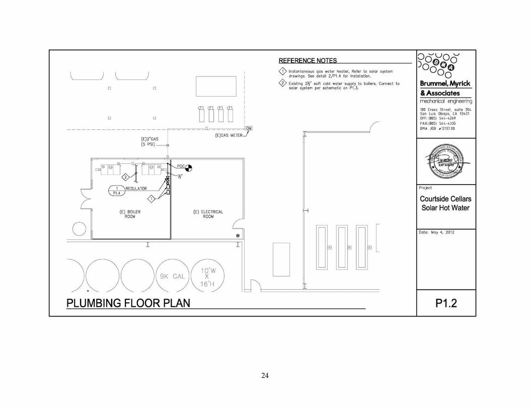
2.6.1 Mechanical
23
24
25
26
2.6.2 Electrical
27
28
29
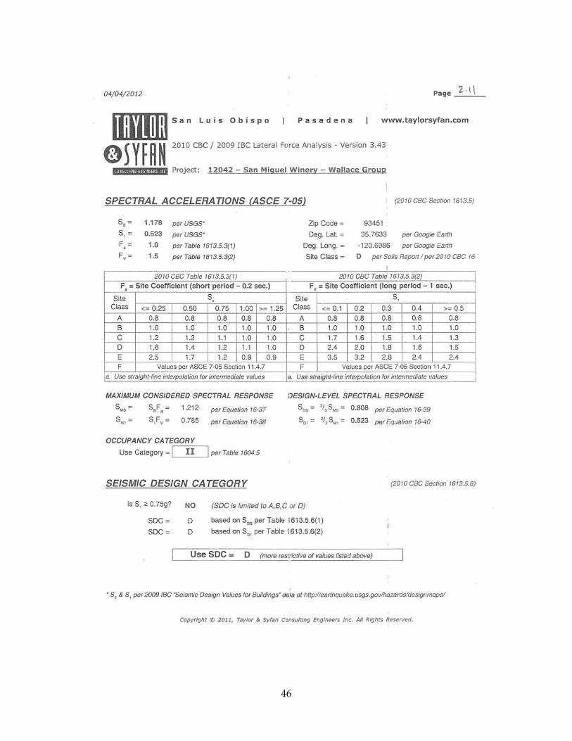
2.6.3 Structural
30
31
32
33
34
35
36
37
38
39
40
41
42
43
44
45
46
47
48
49
50
51
52
53
54
55
2.6.4 Permitting A construction permit for the “Roof Mounted Solar Water Heating System for Existing Wine Processing Building” was issued by the San Luis Obispo County Department of Planning and Building. Permit Number PMT2011‐02036 was issued May 25, 2012. The following applicable codes applied:
2008 California Energy Code 2010 California Building Code, Vols 1 &2 (2009 IBC) 2010 California Electric Code (2008 NEC) 2010 California Fire Code (2009 IFC) 2010 California Green Building Code (New) 2010 California Mechanical Code (2009 UMC) 2010 California Plumbing Code (2009 UPC) 2010 California Reference Standards Code 2010 California Residential Code (New) (2009 IRC) County Building and Construction Ordinance – Title 19 County Coastal Zone Land Use Ordinance – Title 23 County Fire Code Ordinance – Title 16 County Land Use Ordinance – Title 22
56
CHAPTER 3: Installation Commissioning Consultant: Dave Hammontree, Solar Usage Now
Installation Contractor: Knecht’s Plumbing & Heating, Inc.
Figure 17: Atmospheric Storage Tanks, Tankless Water Heaters, Data Acquisition System, Controller, and Pumps
Figure 18: Structural Reinforcements to the Roof Joists
System Installation: August 10, 2012
Insulation: Insulation of exterior piping was delayed following the installation. The insulation package was completed on October 6, 2012.
DAS Commissioned: August 2012
The installation began with the structural reinforcement of the roof joists per the structural analysis. A 2 x 10 inch #2 Douglas Fir was sistered to each roof joist at each solar collector frame mounting foot location. Figure 18 shows the structural reinforcements dictated by the structural analysis.
On top of the lower tier roof a mounting platform was constructed to install the solar collectors at the specified pitch (Figure 19). The mounting platform accounts for the slope of the roof and the appropriate (1/4 inch per foot) slope towards the atmospheric storage tanks (located to the left). The slope
57
towards the storage tanks is crucial for maintaining the required drainback function. When the temperature set point is achieved in the atmospheric storage tanks the pump shuts off and the water drainsback to the storage tanks. Water is circulating through the system only when there is a call for heat (i.e. to satisfy the temperature setpoint). Once the setpoint was satisfied the solar collectors sit idle. Figure 20 shows a detailed view of the framing platform.
The solar collectors are shown in Figure 21. Five individual panels are installed in series for this facility. Shown on the left side of the collectors is the supply piping that continues behind the solar collectors and the return piping is shown in the fore ground. Specific requirements from the site called for the use of ProPress copper fittings. Traditional sweat fittings were only allowed under special situations.
Mounted to the solar collector header on the left is a pyranometer that measures available solar indices continuously (Figure 22). The pyranometer is installed at the same angle as the collectors (35 degrees). The output measurement from this device is monitored by the DAS.
The natural gas measurement devices are shown in Figure 23. A Romet (Model RM3000‐DCID)
Figure 19: Solar Collector Framing
Figure 20: Close up of Framing Detail
Figure 21: West-Facing Solar Collectors
58
rotary meter (shown in the upper right corner) measures the natural gas supply to the existing boilers. Upstream of that measurement location is a branch line the feeds natural gas to the tankless water heaters (shown in the bottom center) with an Itron (Model 400A) positive displacement meter.
Figure 22. Solar Pyranometer
Figure 23. Natural Gas Measurement Devices
59
CHAPTER 4: Demonstration The test protocol used at Courtside Cellars was to allow the Equinox Heating System to operate as required by the winery to meet the hot water demand profile of the facility. The GTI DAS enabled remote monitoring of the system performance including supply and output water flows and temperatures. The approach provided real‐life operational loads on the system and allowed not only performance analysis, but also insight in to how the system could be adjusted for improved performance to meet the needs of the end user. Data was uploaded to the GTI server on a weekly basis and analyzed using a GTI developed performance analysis spreadsheet tailored to commercial systems utilizing the atmospheric storage tanks and associated hardware. Preliminary data was collected once the system was commissioned in August 2012. The exterior piping was insulated in October 2012 and full data monitoring was initiated.
Figure 24 shows the Equinox Heating System monthly natural gas‐only efficiencies, compared to the monthly Available Solar Radiation, and variable Load. Figure 25 to Figure 35 show the daily Fuel Efficiencies compared to Available Solar Radiation, and Load. During the winter months, December 2012 to March 2013, the natural gas‐only efficiencies exhibit a decline, and there were three reasons for this decline in efficiency: 1) Lower available solar radiation, 2) Lower ambient temperature, and 3) Large number of days the facility was closed. When the facility was closed, there was no hot water load, and therefore the fuel efficiency was essentially zero. December has the lowest reported fuel efficiency, and that was primarily because the facility was closed for nearly a week and a half during the winter holidays. The Equinox Heating System is located in an unconditioned space, so when there are lower ambient temperatures, there are higher standby losses from the tank and lower fuel efficiencies.
Figure 24: Monthly Natural Gas-Only Efficiencies
60
Figure 25: October Daily Fuel Efficiencies
Figure 26: November Daily Fuel Efficiencies
Figure 27: December Daily Fuel Efficiencies
61
Figure 28: January Daily Fuel Efficiencies
Figure 29: February Daily Fuel Efficiencies
62
Figure 30: March Daily Fuel Efficiencies
Figure 31: April Daily Fuel Efficiencies
63
Figure 32: May Daily Fuel Efficiencies
Figure 33: June Daily Fuel Efficiencies
64
Figure 34: July Daily Fuel Efficiencies
Figure 35: August Daily Fuel Efficiencies
65
Figure 36: September Daily Fuel Efficiencies
To gain an understanding if available solar radiation, ambient temperature, or hot water load had a greater effect on the daily fuel efficiency, these factors were compared against the daily fuel efficiency. The correlation coefficients are shown in Table 3 and illustrated in Figure 37 thru Figure 40. When using all data points, the hot water load had the greatest correlation to fuel efficiency; however, this was because when the facility was closed, there was no heat delivered, consequently the fuel efficiency was zero. When data was filtered for only days the facility was open, the available solar radiation had the greatest effect on fuel efficiency, followed by the ambient temperature.
Table 3: Correlation Coefficient between Fuel Efficiency, Solar Radiation, Ambient Temperature, and Load
All Days Only Days Facility was Open
Factor Correlation Coefficient (R2)
Factor Correlation Coefficient (R2)
Available Solar Radiation 0.02 Available Solar Radiation 0.22
Ambient Temperature 0.02 Ambient Temperature 0.19
Hot Water Load 0.43 Hot Water Load 0.03
66
Figure 37: Daily Solar Radiation Available to Fuel Efficiency
Figure 38: Average Ambient Temperature to Fuel Efficiency
67
Figure 39: Daily Commercial Hot Water Load to Fuel Efficiency
Figure 40: Unfiltered Daily Commercial Hot Water Load to Fuel Efficiency
The atmospheric storage tanks and tankless water heaters were located in an unconditioned space; therefore, as ambient temperature decreases during the winter months, the tanks have higher tank standby losses, and lower fuel efficiencies. A DAS measurement point located within the data logger enclosure represents essentially the ambient temperature of the boiler room. This temperature was compared against the standby loss of the storage tanks. Standby loss periods were selected when there was no hot water draw, no heat input, and the upper tank temperature started at 170.9 °F. The R2 value is 0.52, confirming that as the unconditioned room temperature decreases, there is higher a standby heat loss from the storage tanks (Figure 41).
68
Figure 41: Atmospheric Storage Tank Standby Loss
4.1 Collector Outlet Temperature The available solar radiation to the collector outlet temperature on a monthly basis, filtered during only times when solar pumps are active was compared on Figure 42. The majority of temperatures range between 125 °F and 175 °F. During the winter months with the lowest radiation (October – February), the solar array outlet temperatures were lowest, with the majority at 150 °F or lower, and obviously during the months with the highest solar radiation (June – August), the solar outlet temperatures were the highest with temperatures great than 150 °F about half of the time.
69
Figure 42: Monthly Solar Collector Outlet Temperature and Available Solar Radiation
70
4.2 Solar Thermal Storage Each Collector has a peak output of 6,632 Btu/h; or 33,160 Btu/h for all five collectors. Assuming eight hours of peak solar collection, this equates to a maximum solar collection of 265,280 Btu/day. However, thermal storage availability in the atmospheric storage tanks and maximum solar collector temperature can limit this capacity.
When the solar collector is greater than 250 °F, as an effort to protect the pumps, the system will go into “lockout” mode, and cease to collect solar energy until the temperature again falls below 250 °F. From October 2012 – August 2013, the system experienced no lockout events.
At standard conditions, the thermal storage of water is 8.33 Btu/gal °F (ASHRAE 2012 Handbook, Chapter 13, Equation 9). Each tank is 132 gal, which equates to a thermal storage capacity of 2,200 Btu/°F. Assuming an ambient temperature of 70 °F, and the maximum storage tank temperature of 180 °F, at steady state conditions, this equates to a total thermal storage capacity of 240,000 Btu. However, the system is designed to maintain a tank temperature of at least 130 °F, which leaves a temperature differential of 50 °F, or 107,800 Btu of available solar thermal energy storage capacity. Additionally, for the solar collector pump to engage, there must be a 30 °F temperature differential between the solar collectors and the storage tanks, therefore the collector temperature is required to be at least 160 °F before solar thermal collection can begin. Lowering the tank temperature setpoint would increase the available solar thermal energy storage capacity, and allow thermal collection to begin at lower temperatures.
4.3 Overall System Performance In the pre‐retrofit system, when a water draw occurred, the storage tanks were refilled with cold water. When the temperature of the tanks fell below 140 °F, then they are recharged by the existing boilers. In Figure 43 the pre‐retrofit system flow is characterized by the grey long‐dash lines. In the post‐retrofit system, when a water draw occurred, the storage tanks were refilled with water from the Equinox Heating System. In Figure 43 this flow is shown by the blue short‐dash lines.
The Monthly Energy Balance at Courtside Cellars is detailed in Table 4. Lines 1 – 9 are the energy balance for only the Equinox Heating System. The Natural Gas Only Efficiencies in Line 8 correspond to the efficiencies in Figure 24. Lines 10 – 13 look at the entire system at Courtside Cellars, including the boiler energy input and the entire system output. Lines 14 – 23 compare the pre‐retrofit system efficiencies to the post‐retrofit system efficiencies, which ultimately provide the energy savings. The annual savings equates to $878. Line 26 calculates the savings if the Equinox Heating System was processing the full load at the facility, which would be $2,623.
** Average of previous months Energy Information Agency (EIA)
4.4 Equinox Heating System Sizing At the onset of this project, the Courtside Cellars load was unknown; however, a year of monitoring has revealed the average daily load as 1.6 million Btu. The Equinox Heating System daily load ranged between 0.5 million Btu and 5.0 million Btu. If the average load was known at the beginning of the project, the corresponding collector area could be calculated. Equation 6 recommends collector area for the corresponding load at 128 m2, or 45 collectors. Budgetary restraints of this project did limit the system to five collectors, or a load size of 0.178 million Btu.
Equation 6: NREL Solar Thermal Technology & Applications Solar Water Heating System Sizing
Area collector η x
where
Area(collector) Recommended collector area
L Average daily load
ηsolar Efficiency of solar system (0.5)
Imax Maximum daily solar radiation (0.025 million Btu/m2/day)
As the load increases, the solar energy contributes less of a percentage to the overall heat delivered, and the system efficiency tends to asymptote towards a standard commercial 80 percent efficient water heater. The large load and the budget limitation to five collectors did have an adverse effect on the equinox system efficiencies.
4.5 Emissions Saved Compared to the standard baseline efficiency gas appliances, the system saved approximately 1190therms of natural gas during the year of monitoring. This energy savings corresponds to a potential reduction of 17,500 lbs of greenhouse gas emission per year. The state of California has over 1100 wineries; assuming a 10 percent market penetration, the savings would be 130,000 therms for all sites and a reduction of 1.9 million lbs, or 875 metric tons, of greenhouse gas emissions per year (equivalent to 175 passenger vehicles per year).1
1 The reduction in GHG emissions was calculated using GTI’s Source Energy and Emissions Analysis Tool which includes a source-energy and carbon emission calculation methodology that accounts for primary energy consumption and related emissions for the full-fuel-cycle of extraction, processing, transportation, conversion, distribution, and consumption of energy. This tool, available to the public at www.cmictools.com, was developed based on government data sources. Source Energy and Emissions Analysis Tool features and methodology are further described in a peer-reviewed ASHRAE technical paper available at http://www.techstreet.com/cgi-bin/detail?product_id=1714568. US EPA Estimates an average passenger vehicle has tailpipe emissions of 5.1 metric tons: http://www.epa.gov/oms/climate/documents/420f11041.pdf
4.6 Economic Analysis The actual installation costs for the system are outlined in (Table 5). The final cost for installation, equipment, permitting and engineering totaled $76,048. An alternative system would be a new boiler, which EIA Technology Forecast estimates at $17,000. The cost differential between the two is the incremental cost of the solar system, or $59,048. GTI conducted an analysis for state and local grants and incentives, which would be discounted from the installation costs. Assuming the system met all of the incentive requirements, the final incremental cost after grants and incentives reduced the solar system to a very competitive $6,452. Since the system was not performing optimally in August and September 2013, a full year was of savings was projected from the October 2012 –July 2013 data. With an annual savings of $878, the simple payback for this system is 7.3 years. Another comparison between the baseline system (boilers) and the solar system is the 15 year lifecycle costs, as shown in Table 6. The baseline boiler has a lifecycle cost of $350,034, while the solar system incremental price with incentives has a nearly $20,000 lower cost of $329,866.
Baseline Boiler System2 Total Installed Cost $ 17,000
Incremental Cost $ 59,048
State / Local Incentives
California Solar Initiative - Solar Thermal Program
$14.53 per estimated therm displaced. Maximum incentive is $500,000.1 $ 10,770
Federal Incentives
Corporate Tax Credit 30% Tax Credit For Solar $ 22,814
USDA - Rural Energy for America Program (REAP) Grants2
25% of project cost $ 19,012
Final Incremental Cost After Incentives
$ 6,452
1This amount was calculated using the California Solar Initiative Incentive Calculator and is different than actual therm savings. With this calculator, the "base case" when compared against tankless SDHW systems, will be a tankless water heater. 2 The Baseline System is a 1 million Btu input boiler (80% efficient). The price was obtained from the EIA - Technology Forecast Updates (2011) - Residential and Commercial Building Technologies http://www.eia.gov/analysis/studies/buildings/equipcosts/pdf/appendix-a.pdf
77
Table 6: Fifteen Year Lifecycle Costs
Capital Costs
Annual Energy
Operating Costs
15 Year Energy
Operating Cost
Simplified 15 Year
Lifecycle Cost
Natural Gas Boiler (baseline) $17,000 $22,202 $333,034 $350,034
Solar Thermal/Natural Gas incremental cost
without incentives $59,048 $21,561 $323,415 $382,463
Solar Thermal/Natural Gas incremental cost
with incentives $6,452 $21,561 $323,415 $329,866
4.7 Recommendations for System Performance Enhancements In order to improve the Equinox Heating System fuel and gas‐only efficiencies, GTI recommends having the atmospheric storage tank serve as storage for solar thermal energy only, to preheat the water before it is sent to the tankless water heater, as illustrated in Figure 44. There are four reasons this would lead to higher efficiencies:
1. The Equinox could store more solar energy. Analysis in the section 4.2 Solar Thermal Storage, determined that at steady state conditions the tanks have a heat storage capacity of 240,000 Btu. However, maintaining a minimum tank temperature of 130 °F leaves only 107,800 Btu for solar thermal energy storage. If a minimum tank temperature was not maintained, the full heat storage capacity could be utilized for solar thermal storage.
2. The Equinox could collect additional solar energy. A 30 °F temperature differential between the storage tank and the solar collector was required before the system can initiate solar collection. The tank was required to maintain a minimum temperature of 130 °F, so generally the collectors must be at least 160°F before solar collection can initiate. If the storage tank temperature was lower, then the system could begin to collect solar energy at lower temperatures.
3. All standby losses from the storage tanks would be from solar energy only. At a very minimum, the Equinox system would have the efficiency of the tankless water heaters.
4. On days when there is no hot water load, the facility would use no natural gas. If the storage tanks were not able to maintain a set temperature, then the tankless water heaters would boost the temperature only when there was a load.
78
Figure 44: Atmospheric Storage Tank as Preheat Tank
79
CHAPTER 5: Technology Transfer 5.1 Equipment The Equinox Heating System design requires only a limited amount of standard equipment for assembly. This limits capital investment while allowing redundancy that minimizes potential for production interruptions resulting from any fabrication equipment breakdowns.
Figure 45: Solar Usage Now Warehouse
5.2 Facilities
Solar Usage Now’s facility in Hamilton, Indiana includes a warehouse housing a large inventory of equipment and a training facility (Figure 46) for distributors and installer. The training is mandatory for larger commercial installations to assure safe, trouble‐free, cost effective and efficient installation and operation of the Equinox Heating System in the field.
Figure 46: Solar Usage Now Training Facilities
80
5.3 Personnel Resources Key management personnel are well qualified and include Thomas Blake Sr., President and CEO, Thomas Blake Jr., who provides design and other technical guidance and Donald Renner, who heads up production. Other dedicated team members focus on accounting, sales, purchasing, logistics and coordination, operations, and production. The twelve senior team members fill key full‐time functional positions and can support any potential production demands. Additional resources are brought on board on an as needed basis to meet production needs.
5.4 Support Systems Solar Usage Now is the sole importer atmospheric storage tanks manufactured by Rotex and of KU solar products in the US and has agreements in place supporting procurement of other key components to facilitate production of the Equinox Heating System to meet customer needs. The training facility located at the manufacturing site, is used to provide mandatory training to all distributors and installers regardless of their prior experience. Mechanical contractors are required to complete the training and assist in breaking down their Equinox Heating System, which eliminates the guesswork at the job site and allows for smoother installation. Solar Usage Now has in place a network of approximately 250 dealers across the U.S. and Canada that have multiple feet on the ground working with their existing customer base, visiting specifying engineers, and following up on solar leads.
81
CHAPTER 6: Conclusions The Gas Technology Institute (GTI), along with its partner Solar Usage Now designed and developed a highly efficient prototype solar‐assisted gas hot water heating system for commercial applications. The system, called the Equinox Heating System, was development to reduce the material, manufacturing, and installation cost of solar‐assisted natural gas water heating systems for use in small commercial, industrial, and agricultural applications. The system was installed at the field demonstration site, Courtside Cellars, in San Miguel, California to verify performance of the technology in an applied environment. It has been operating continuously as required by the winery to meet the hot water demand profile of the facility. A data acquisition system collected data simultaneously to record the system variation and characterize performance.
The Equinox Heating System is a combination of an atmospheric storage tank, a highly efficient natural gas‐fired tankless water heater, and a very efficient solar thermal collector. The result is a highly efficient hot water delivery system designed to meet the reliability and performance needs of hot water process found in small to mid‐size wineries located throughout California. The modular design of the hot water storage tank makes them ideal to be linked together to replace boilers used for commercial applications such as hotels, schools, hospitals, etc. The design reduces and eliminates major components and associated costs, such as a second storage tank for solar, but affords maximum flexibility for installation and utility business considerations. The implementation of a high‐efficient drainback solar collector expands the market for solar water heating, particularly to areas where freeze protection is required.
Under the context of the Energy Commission grant installing enough capacity to replace both existing boilers was estimated to be larger than what was economically possible. The path forward was determined to augment the existing boiler capacity with the Equinox Heating System. A year of monitoring has revealed the average daily load as 1.6 million Btu. The Equinox Heating System daily load ranged between 0.5 million Btu and 5.0 million Btu. An appropriately sized solar collector would be 128 m2, or 45 collectors.
Overall, the Equinox Heating System performed extremely well; at peak conditions, at peak conditions the fuel efficiency was over 95 percent, generating more than 1,700 gallons of hot water daily. Compared to the standard baseline efficiency gas boiler, the system saved approximately 1190 therms of natural gas during the year of monitoring. This energy savings corresponds to a potential reduction of 17,500 lbs of greenhouse gas emission per year.
The estimated payback period for the Equinox Heating System was 7.3 years coupling with the present incentives provided by state and federal governments. Payback periods are dependent upon the solar fraction and the available incentives. Solar‐assisted systems can currently provide a financially viable alternative over traditional water heating systems as documented in the 15 year lifecycle cost.
82
83
GLOSSARY
PIER‐Public Interest Energy Research
RD&D‐Research, Development, and Demonstration
GTI‐Gas Technology Institute
FTA‐Field Test Agreement
HP‐Horsepower
P&ID‐Piping and Instrumentation Diagram
EF‐Energy Factor
DAS‐Data Acquisition Systems
EIA‐Energy Information Agency
APPENDIX A: Equinox Equipment Specifications Atmospheric Storage Tank