Page 1
1
Solar Electric and Solar Thermal Energy:
A Summary of Current Technologies
November, 2014
Tayyebatossadat P. Aghaei
Research Associate, Global Energy Network Institute (GENI)
[email protected]
Under the supervision of and edited by
Peter Meisen
President, Global Energy Network Institute (GENI)
www.geni.org
[email protected] (619) 595-0139
Page 2
2
Table of Contents Abstract ........................................................................................................................................... 5
1 Introduction ............................................................................................................................. 6
1.1 Nature of Solar Energy ........................................................................................................ 6
1.2 History of Solar Energy ....................................................................................................... 7
2 Large-scale Solar Thermal Technology Systems .................................................................... 9
2.1 Flat- plate Collector .................................................................................................................. 9
2.2 Concentrator Collector ............................................................................................................ 12
3 Non-power Plant Applications of Solar Energy .................................................................... 13
3.1 Solar Water Heater .................................................................................................................. 13
3.2 Solar Heating and Cooling ...................................................................................................... 14
3.3 Solar Cooling System ........................................................................................................ 15
3.4 Solar Desalinization ........................................................................................................... 15
3.5 Solar Dryer ......................................................................................................................... 16
3.6 Solar Cooke ........................................................................................................................ 17
3.7 Solar Furnace ..................................................................................................................... 18
4 Solar Power Plant Technology .............................................................................................. 18
4.1 Parabolic Trough Power Plant ................................................................................................ 18
4.2 Central Receiver System (CRS) Power Station ...................................................................... 19
4.3 Stirling Dish Power Plants ...................................................................................................... 20
4.4 Solar Chimney Power Plant .................................................................................................... 22
4.5 Fresnel Solar Power Station .................................................................................................... 23
5. Photovoltaic (PV) Power Systems ......................................................................................... 25
5.1 Photovoltaic Systems Applications......................................................................................... 28
5.2 Methods for Using Photovoltaic Energy................................................................................. 28
5.3 Photovoltaic Power System Applications ............................................................................... 29
6. Global Solar Energy Statistics .............................................................................................. 32
6.1 Concentrating Solar Power (CSP)/Concentrated Solar Thermal (CST) ................................. 32
6.2 Solar photovoltaic (PV) .......................................................................................................... 33
7. Conclusion .......................................................................................................................... 35
8. Bibliography .......................................................................................................................... 36
Page 3
3
Appendix ....................................................................................................................................... 40
Table of Figures
Figure 1: Equation of Mass Energy Equivalence .......................................................................... 6
Figure 2:Anatomy of a solar flat plate collector .......................................................................... 10
Figure 3:Trickling-down water collector ..................................................................................... 11
Figure 4: Solar water heater diagram .......................................................................................... 14
Figure 5: Passive solar heating .................................................................................................... 15
Figure 6: A schematic of a direct solar dryer ............................................................................... 16
Figure 7:Indicator solar dryer ...................................................................................................... 16
Figure 8: Solar cookers designs ................................................................................................... 17
Figure 9: Solar furnace ................................................................................................................ 18
Figure 10: A diagram of a parabolic trough solar farm (top) and an end view of how a parabolic
collector focuses sunlight onto its focal point……………………………………………………19
Figure 11: Diagram illustrating the central receiver principle ..................................................... 20
Figure 12: Stirling dish power plant ............................................................................................ 21
Figure 13 Stirling power plant diagram ....................................................................................... 22
Figure 14: Solar Chimney power plant ........................................................................................ 23
Figure 15: Fresnel Solar Power Station ....................................................................................... 24
Figure 16: Crystalline Silicon Cell Structure ............................................................................... 27
Figure 17: Layers of a solar cell ................................................................................................. 28
Figure 18: grid-connected small solar electric systems ............................................................... 29
Figure 19: Application of solar water pumping system ............................................................... 30
Figure 20: Solar lighting .............................................................................................................. 30
Figure 21: The winning car in the 1996 World Solar Challenge ................................................ 31
Figure 22: Cathodic Protection Controller (CP) .......................................................................... 31
Figure 23: World installed concentrating solar thermal power capacity ..................................... 33
Figure 24: Evaluation of total PV installed capacity from1992 to 2012 .................................... 34
Page 4
4
Power Terminology
1. GWh – Gigawatt hour: The gigawatt is equal to one billion (109) watts or 1 gigawatt =
1000 megawatts.
2. kV – kilovolt
3. kWh – kilowatt hour
4. PV – Photovoltaic
5. MV –Megavolt: A megavolt is 1 million volts in electronics and physics.
6. MW – Megawatt: a megawatt is equal to one million (106) watts
7. MWe – Megawatt electrical
List of Abbreviations
PV-Photovoltaic
CSR-Central Receiver System
CPV-Concentrated photovoltaic
DG-distributed generation
DC-direct current
AC-alternating current
IEA- International energy Agency
NASA- National Aeronautics and Space Administration
BC-Before Christ
Page 5
5
Abstract
Energy is the most valuable resource and foundation of civilization. It is also our heritage for
future generations. Preserving this resource for future requires a thorough understanding of
energy resources, optimal operation and sustainable usage. Solutions that previously seemed
impossible or too expensive, today, are technically and economically achievable. Application of
new capacity generated by renewable energy sources, new management systems, advanced
technologies and improving productivity can contribute to economic growth.
Solar energy is one of the most important sources of energy as it is free and no other country can
charge for the use of the sun. Solar energy, on the other hand can be important because this
energy is infinite.
Solar energy received by the earth in one hour is more than the energy used by world’s
population in one year. World attention to solar energy has risen recently due to technology
development and lower cost of installation and operation along with environmental concerns
about fossil fuels. According to experts, solar energy will soon become the favorite energy used.
Increasing the efficiency of photovoltaic systems and reduced costs of associated equipment has
impacts on this explosive growth.
Addressing the issues related to solar energy and renewable energy is important for everyone.
This report investigates the nature of solar energy; various ways of exploiting it; and examining
the state of the art technologies used to provide power from this profitable energy.
Key words:
Energy, renewable energy, fossil fuel, sun, solar energy, solar cell
Page 6
6
1 Introduction
1.1 Nature of Solar Energy
The sun is a main source of renewable energy that could provide a limitless source of energy
supply in many parts of the world. Lack of sun can easily end life. Without the Sun, the Earth's
temperature will drop suddenly and Earth will be cold and dark, so no plant life and no human on
earth will exist (NASA). The sun is the cause and origin of the various energy sources which are
exist in the nature, such as fossil fuels which are stored deep in the earth; waterfalls and wind
energy; plant, animal, and human growth; all organic matter that can be converted to heat and
mechanical energy; along with sea waves, gravitational and tidal power occurs upon earth moves
around the sun and moon.
Solar energy is produced through deep nuclear fusion reactions. In a fusion process, two atomic
nuclei collide at very high speed and create a new form of nucleus. It can be done due to the
extremely high temperature and high density in the sun’s core. Although the positive charges
tend to repel each other, they stay together due to the high temperature and density of the sun's
core. (NESTA, National Earth Science Teachers Association)
The most common fusion in the sun is called the proton-proton chain. This process begins when
the simplest form of the hydrogen nucleus (contain one proton) close together just for a moment.
First a nucleus composed of two subatomic particles is created (deuterium formation) then
deuterium fuses with another proton and a triple subatomic particle is created (helium nuclei).
Two helium-3 nuclei fuse together and a nucleus with four subatomic particles is created (alpha
particle form) also an electrically neutral subatomic particle called a neutrino produced in this
process (nave, 2000). Finally, the nucleus, which is helium, consists of two protons and two
neutrons. The Helium mass is slightly less than the mass of the four protons which it has been
made from. This lost mass is converted into
energy. The amount of this energy can be
calculated by the famous formula E=mc2
discovered by German physicist, Albert
Einstein. In this equation, E represents
energy, m the mass, and c is the speed of
light. (nave, 2000) Figure 1: Equation of Mass Energy Equivalence
Source: Jha 2010
Page 7
7
1.2 History of Solar Energy
The use of solar energy dates back to the seventh century BC .it was used for heating, cooking,
lighting or making fires. 1
Ancient Greeks and Romans was the first people who built their houses with solar
heating and sunlight benefits.
Seventh century BC: Ancient people used the magnifying glass to focus sunlight in order
to light fires.
Third century BC: Romans and Greeks used mirrors to light their torches.
The second century BC: The Greek scientist, Archimedes, used reflected solar radiation
from the sun and focused through a bronze shield.
In the fourth century AD: Roman bathes were designed to heat water by using sunlight.
In the thirteenth century: Pueblo Indians in North America built their cliff homes facing
south to take advantage of sun heat during the winter.
In 1767: Swiss scientists built the first solar collector.
In 1816: Scottish minister Robert Stirling patented his invention to pre-heat the engine
heater. Later this invention was used in the generation of electricity by solar heating.
In1839: French scientist Edmund Becquerel discovered the photovoltaic effect. While he
was working with electrolysis cell with two metal electrodes in the electrolyte dilution. he
found out that when he placed it in the sun, the electricity generation rate would be
increased.
In 1860: French mathematician August Mouchet began to work on the solar steam
engine. After 20 years, he and his assistant, Abel Pire, built a prototype of modern
engines that are currently used in parabolic linear collectors.
In 1837: Willoughby Smith discovers the photoconductivity of selenium.
In1876: William Grylls Adams and Richard Evans Day discovered that selenium
generates electricity when it is placed in the sun.
In 1880: Samuel P. Langley invented a bolometer, a device to measure the power of solar
thermal radiation.
In 1883: Americans Charles Fritts, thought the idea of making solar cells from selenium
wafers.
In 188: Heinrich Hertz discovered that ultraviolet radiation provides the minimum
voltage required for spark between two electrodes.
In 1891: The first solar water heater was patented by American Clarence Kemp.
In 1904: Wilhelm Hallwachs discovered that copper and copper oxides are photosensitive
together.
In 1905: Albert Einstein, with his theory of relativity, outlined the photoelectric effects.
In 1908: William J. Bailey, mad a collector with copper coils and an insulated box
1 For full detail go to: https://www1.eere.energy.gov/solar/pdfs/solar_timeline.pdf
Page 8
8
In 1916: the photoelectric effects have been proved experimentally by scientists.
In 1918: Polish scientist Jan Czochralski discovered how to grow single crystal silicon.
In 1921: Albert Einstein received the Nobel Prize for his theory of the photoelectric
effect.
In 1932: photovoltaic effect in cadmium sulfide was detected.
In 1954: three American scientists developed the first silicon photovoltaic cell.
In mid-1950s: the world's first commercial office building which worked with solar water
heater was designed.
In 1963: Japan installed a 24 watt panel on a lighthouse.
1964: NASA's first satellite with a capacity of 470 MW fed by photovoltaic cells
launched in space.
In 1969: solar furnace using 8parabolic mirrors built in Odeillo, France.
1970: Elliot Berman designed cheaper solar cells; extensive use of photovoltaic becomes
possible.
In 1976 AD: NASA Lewis Research Center for the first time began to install 83
photovoltaic systems across the world to provide light in clinics, water pumping and etc.
In 1981: the first solar plane flew from France to England.
1986: the largest solar thermal power plant at that time was launched in California.
In 2001: thin film photovoltaic was made.
In 2002: the largest rooftop solar systems were installed in California.
In 2008: the largest solar park using thin film systems was established in Germany.
In 2013: 930 megawatts of photovoltaic (PV) systems were installed in United States,
which represents the largest quarter ever for residential PV installations ever.
Page 9
9
2 Large-scale Solar Thermal Technology Systems
Solar thermal systems include those that are based on low temperature thermal collectors. These
systems use heat from the sun for the final heat consumption. This technology system consists of
two groups of flat solar collectors and a low concentration solar collector (concentrator
collectors).
Thermal systems have a storage unit to provide heating at night. Most solar thermal systems are
used for heating water in commercial buildings, swimming pools, water, large homes, apartment
buildings and hotels. Also, a large part of the demand is for space heating/ cooling of buildings
and supplying power for absorption heat pumps2 with solar thermal technologies.
Some of the basic concepts of thermal systems are as follows:
Working fluid is used to transfer the absorbed heat for suitable usage a heat transfer fluid
such as oil, water or air is needed.
Absorbent surfaces: dark surfaces made from different technologies to maximize the
absorption of thermal energy. In solar power plants, absorbent surfaces are exposed
where the sun is shine or is concentrated.
Thermal storage system: stores solar energy to use at night or on a cloudy day. In solar
water heaters, hot water storage tanks are used and in power systems, thermal energy is
stored in reservoirs containing oil and sand. 3
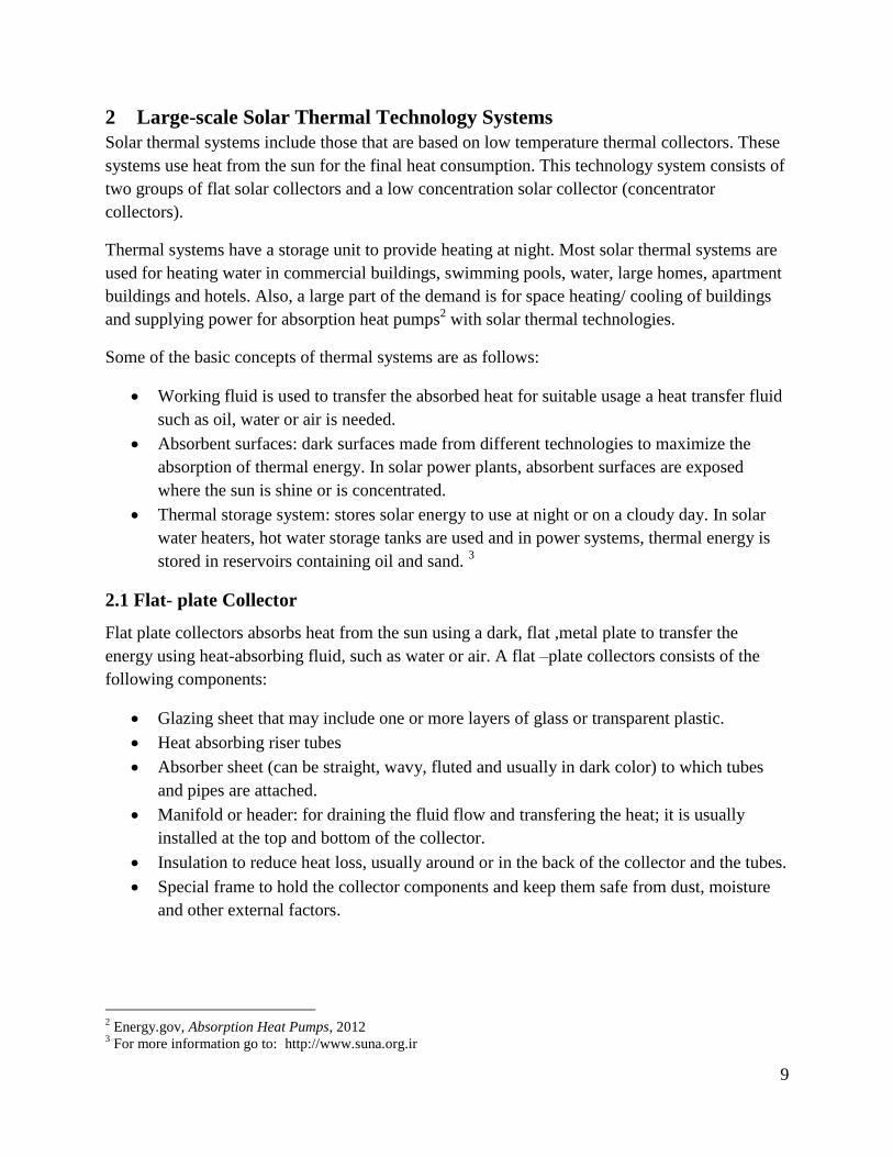
2.1 Flat- plate Collector
Flat plate collectors absorbs heat from the sun using a dark, flat ,metal plate to transfer the
energy using heat-absorbing fluid, such as water or air. A flat –plate collectors consists of the
following components:
Glazing sheet that may include one or more layers of glass or transparent plastic.
Heat absorbing riser tubes
Absorber sheet (can be straight, wavy, fluted and usually in dark color) to which tubes
and pipes are attached.
Manifold or header: for draining the fluid flow and transfering the heat; it is usually
installed at the top and bottom of the collector.
Insulation to reduce heat loss, usually around or in the back of the collector and the tubes.
Special frame to hold the collector components and keep them safe from dust, moisture
and other external factors.
2 Energy.gov, Absorption Heat Pumps, 2012
3 For more information go to: http://www.suna.org.ir
Page 10
10
Figure 2:Anatomy of a solar flat plate collector
Source: (Solar fred, 2010)
Flat-plate collectors based on fluid bed type, structure and function are divided in to three
categories, namely:
Trickling-water collector
Liquid-based collector
Air-based collector
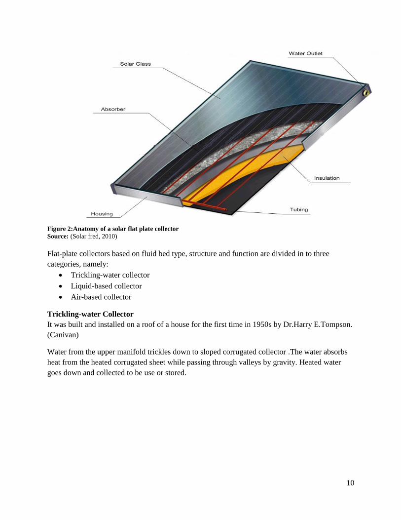
Trickling-water Collector
It was built and installed on a roof of a house for the first time in 1950s by Dr.Harry E.Tompson.
(Canivan)
Water from the upper manifold trickles down to sloped corrugated collector .The water absorbs
heat from the heated corrugated sheet while passing through valleys by gravity. Heated water
goes down and collected to be use or stored.
Page 11
11
Figure 3:Trickling-down water collector
Source: Alternative Energy Tutorials
Liquid-based Collector
The working fluid on these collectors is usually water, oil or liquid with a low freezing point.
Freezing of the water in the collector and the corrosion are the major problems in these types of
collectors.
Flat plate collectors, collect direct and diffuse solar radiation so they don’t need tracking
systems. Although they having large heat absorbing-surface, they produce less heat with lower
temperature in compare with concentrator collectors.
They are suited to warm up the water and air as they are less expensive than concentrator
collectors.
Air-based Collector
In this type of collector, air or gas is used as a medium to transfer the heat. The advantage of this
collector over the other types of liquid collectors is that there is zero corrosion and zero air frost.
Having less weight than liquid-based collectors is another advantage of this type of collector as
they don't have pressurized piping. Nevertheless, difficulty to regulate and low heat storage
capacity of air are the main reasons why air-based collector are not that much common.
Page 12
12
2.2 Concentrator Collector
With the help of advanced geometric design, direct solar radiation and part of diffused solar
radiation are concentrated with concentrator collectors. With this type of collector, reflection
surface are used to increase solar radiation. In order to achieve high temperatures, solar radiation
will be concentrated in the focal area, for this purpose, concentrator collector must be able to
track the sun during the day. Focusing on the focal area boosts given energy per unit.
Heat dissipation is reduced due to decreases in absorption surface, so higher temperatures and
more heat is produced. Concentrator collector is not designed to use in cloudy conditions.
In comparison with flat-plate collector they have higher costs of regulation. Although they have
a lower efficiency in low temperature, their efficiency is good in high temperature. The intensity
of intake solar radiation by concentrator can get about 70-80 times more than flat collectors also
they don’t need insolation however it is crucial for flat collector. (suna)
Page 13
13
3 Non-power Plant Applications of Solar Energy
There are a number of small scale solar energy technology options available for home and small
businesses usage. These include:
Solar water heating
Solar heating and cooling
Passive solar heating
Active solar heating system
Solar cooling system
Solar desalinization
Direct solar dryer
Indirect solar dryer
Solar cooker
Solar furnace
These systems use flat-plate collection technologies and each is described in the following pages.
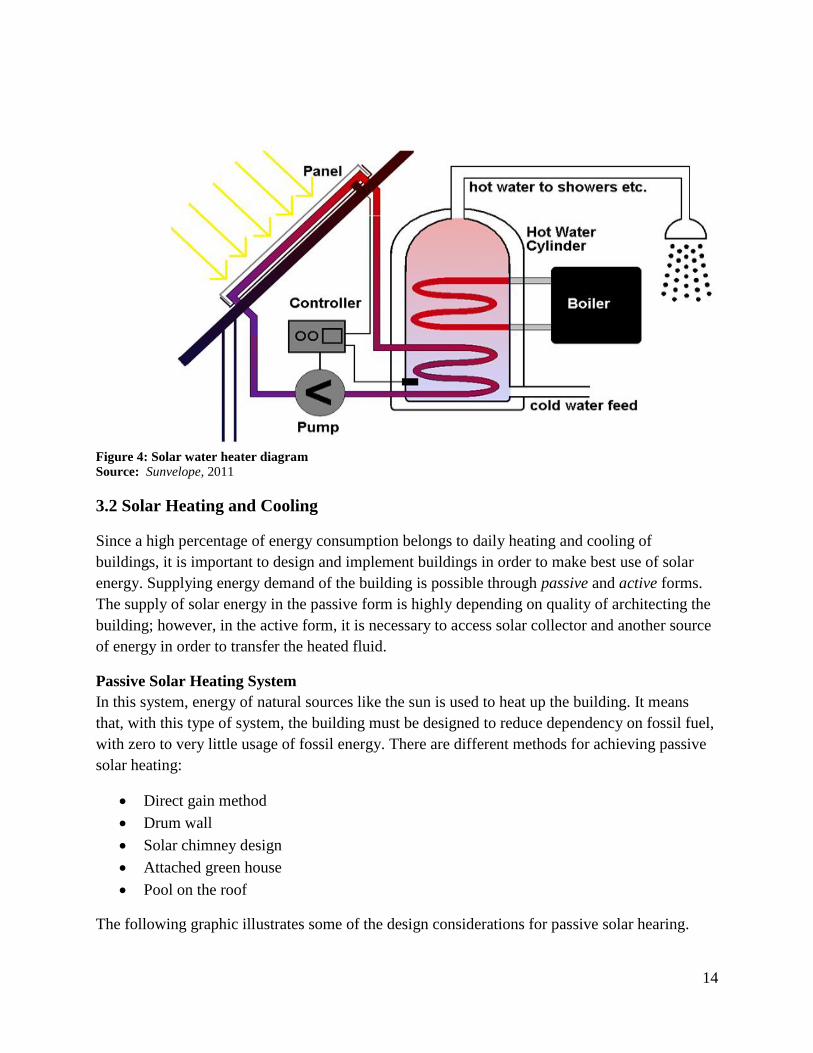
3.1 Solar Water Heater
These use solar energy to heat the water. They are composed of three parts: a collector, circuit
piping, and heat storage tanks.
In most modern water heater, water and antifreeze solution moves between the tank and the
collector in a closed cycle by circuit piping. The collector absorbs the sun's heat energy and
transfers it to the working fluid. Heated fluid moves toward the storage tank where it passes
through a heat exchanger and transfers its heat to the water in storage tank; after cooling down it
goes back to the collector again so without mixing with consumable water, it always moves in
closed cycle.
Solar water heaters fit into two categories, open and closed circuit systems. In both categories,
they can work in thermosyphon (natural flow – a passive heat exchange) or a pump (forced heat
exchange).The important part of the solar water heaters is the collector, in which the plate is
heated by solar radiation and transferred its heat to the working fluid. This plate is always a dark
color and has a special coating that maximizes energy absorption and minimizes heat dispersion.
To achieve high temperatures, the plate and tube are set inside an insulated box covered with
glass to optimize the greenhouse effect.
Page 14
14
Figure 4: Solar water heater diagram Source: Sunvelope, 2011
3.2 Solar Heating and Cooling
Since a high percentage of energy consumption belongs to daily heating and cooling of
buildings, it is important to design and implement buildings in order to make best use of solar
energy. Supplying energy demand of the building is possible through passive and active forms.
The supply of solar energy in the passive form is highly depending on quality of architecting the
building; however, in the active form, it is necessary to access solar collector and another source
of energy in order to transfer the heated fluid.
Passive Solar Heating System
In this system, energy of natural sources like the sun is used to heat up the building. It means
that, with this type of system, the building must be designed to reduce dependency on fossil fuel,
with zero to very little usage of fossil energy. There are different methods for achieving passive
solar heating:
Direct gain method
Drum wall
Solar chimney design
Attached green house
Pool on the roof
The following graphic illustrates some of the design considerations for passive solar hearing.
Page 15
15
Figure 5: Passive solar heating
Source: Evans and Evans, 2007
Active Solar Heating
In the active system, different elements are used to supply heat for a building. Components used
in these systems include collectors, thermal energy storage, fluid flow channels, pumps, piping,
valves, dampers, manual or automatic control systems, auxiliary fuel systems and heat
exchangers.
3.3 Solar Cooling System
Although solar heating systems are relatively inexpensive, solar cooling is difficult and
expensive. In general, there are two solutions for solar cooling:
Convert solar energy into electrical or mechanical energy and enable its use in
compression chiller systems, or
Convert solar energy into thermal energy and use it in the operation of an absorption
chiller system.
3.4 Solar Desalinization
Principles of solar water purifier are simple. Plastic or glass cover on the top surface of the
device plays a key role in the performance of this system.
The sun's rays passing through the brine pool and increased the temperature of the water inside
to heat; produced steam hit the inner surface of the cover glass which has a temperature lower
than the temperature of seawater desalination and began to distill. By collecting the distilled
water, fresh water is obtained.
Page 16
16
Solar desalination performances can be divided into two terms: Direct and Indirect methods. In
direct method solar thermal energy is just used however in indirect method electrical energy is
used as an alternate energy. Solar desalination must be designed according to the climate and
weather condition of the interest regions.
3.5 Solar Dryer
This technique uses direct or indirect solar thermal energy with natural or forced air flow causes
drying of the substances.
Direct Solar Dryer
It has easy and inexpensive application with no possibility of controlling the heat temperature. In
this way, if fruits and vegetable overexposed by the sun, their color will be change and they lose
plenty of their vitamins.
Figure 6: A schematic of a direct solar dryer
Source: A. K. Karthikeyan, 2013
Indirect Solar Dryer In this system, the temperature can be
controlled and food is not directly
exposed by the sunlight so color remains
constant. This device fits the needs of the
villages in the drying of fruits and
vegetables, as well as in industrial dried
rice and vegetable production.
Figure 7:Indicator solar dryer
Source: Terra Fundacion
Page 17
17
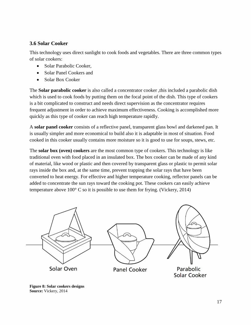
3.6 Solar Cooker
This technology uses direct sunlight to cook foods and vegetables. There are three common types
of solar cookers:
Solar Parabolic Cooker,
Solar Panel Cookers and
Solar Box Cooker
The Solar parabolic cooker is also called a concentrator cooker ,this included a parabolic dish
which is used to cook foods by putting them on the focal point of the dish. This type of cookers
is a bit complicated to construct and needs direct supervision as the concentrator requires
frequent adjustment in order to achieve maximum effectiveness. Cooking is accomplished more
quickly as this type of cooker can reach high temperature rapidly.
A solar panel cooker consists of a reflective panel, transparent glass bowl and darkened pan. It
is usually simpler and more economical to build also it is adaptable in most of situation. Food
cooked in this cooker usually contains more moisture so it is good to use for soups, stews, etc.
The solar box (oven) cookers are the most common type of cookers. This technology is like
traditional oven with food placed in an insulated box. The box cooker can be made of any kind
of material, like wood or plastic and then covered by transparent glass or plastic to permit solar
rays inside the box and, at the same time, prevent trapping the solar rays that have been
converted to heat energy. For effective and higher temperature cooking, reflector panels can be
added to concentrate the sun rays toward the cooking pot. These cookers can easily achieve
temperature above 100° C so it is possible to use them for frying. (Vickery, 2014)
Figure 8: Solar cookers designs
Source: Vickery, 2014
Page 18
18
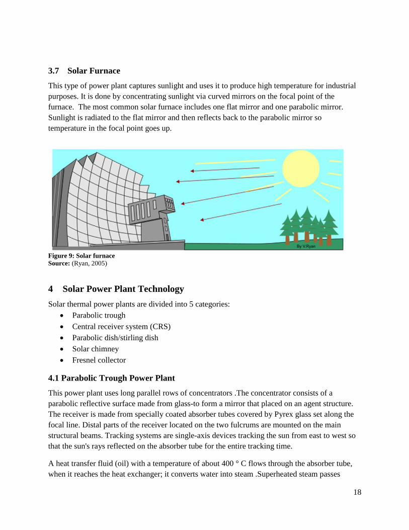
3.7 Solar Furnace
This type of power plant captures sunlight and uses it to produce high temperature for industrial
purposes. It is done by concentrating sunlight via curved mirrors on the focal point of the
furnace. The most common solar furnace includes one flat mirror and one parabolic mirror.
Sunlight is radiated to the flat mirror and then reflects back to the parabolic mirror so
temperature in the focal point goes up.
Figure 9: Solar furnace
Source: (Ryan, 2005)
4 Solar Power Plant Technology
Solar thermal power plants are divided into 5 categories:
Parabolic trough
Central receiver system (CRS)
Parabolic dish/stirling dish
Solar chimney
Fresnel collector
4.1 Parabolic Trough Power Plant
This power plant uses long parallel rows of concentrators .The concentrator consists of a
parabolic reflective surface made from glass-to form a mirror that placed on an agent structure.
The receiver is made from specially coated absorber tubes covered by Pyrex glass set along the
focal line. Distal parts of the receiver located on the two fulcrums are mounted on the main
structural beams. Tracking systems are single-axis devices tracking the sun from east to west so
that the sun's rays reflected on the absorber tube for the entire tracking time.
A heat transfer fluid (oil) with a temperature of about 400 ° C flows through the absorber tube,
when it reaches the heat exchanger; it converts water into steam .Superheated steam passes
Page 19
19
through a turbine, generating electrical energy. This type of power plant with heat storage is
capable of generating electricity even after sunset.
Figure 10: A diagram of a parabolic trough solar farm (top) and an end view of how a parabolic collector
focuses sunlight onto its focal point. Source: Andrew Buck, 2008
The main components of a parabolic power plant include:
Parabolic reflectors
Receiver; to absorb reflected radiations and heat the heat transfer fluid.
Steel made supporter and foundation
Electric power production systems
Heat transfer equipment
Equipment to transfer heat loss to the outside environment
4.2 Central Receiver System (CRS) Power Station
This system includes a set of mirrors (heliostat) that each separately concentrate solar energy and
reflect it to the central receiver on the top of the tall tower. Energy collected in the central
receiver is transferred to the heat exchanger mounted on the tower, where water is converted to
super-heated steam. This steam drives a generator turbine that is installed at the bottom of tower
to produce electricity.
Page 20
20
Figure 10: Diagram illustrating the central receiver principle
Source: (Solar PACES)
The main components of a CRS power station:
• Heliostat, solar radiation collector system
• Central receiver, which absorbs heat from solar radiation and make it usable.
• Thermal energy transfer system absorbs heat passed through receiver and moves it
around. In the basic design, water and steam is used as an absorbent and heat transporter
fluid, however in the more developed designs, molten sodium and potassium have been
used.
• The power conversion system
• Energy storage system
4.3 Stirling Dish Power Plants
These power plants use sunlight beamed on surface of the parabolic concentrator and
accumulated on the focal point. For these systems to be effective, the collectors must always
track the sun. So they need dual-axis tracking mechanisms. In such systems, sunlight is
concentrated on the focal point and a Stirling engine converts the concentrated thermal energy in
to mechanical energy. Then an alternator uses this mechanical energy to generate electricity.
Page 21
21
Figure 11: Stirling dish power plant
Source: TCS Power
The main components of Stirling dish power plants include:
• Concentrator surfaces that focus the rays of the sun at the focal point.
• Stirling engine converts concentrated thermal energy in to mechanical energy and
generate electricity via an alternator.
• Tracking system and control system tracks the sun making sure that the receivers are
always pointing toward the sun surface to focus the light on the receiver of Stirling
engine. Control system uses different information coming from different sensors and the
Stirling engine to issue right control signal in any command mode.
• Structural and foundation: to keep the concentrators, Stirling engines and other
components safe from withstand inertia loads, wind and earthquakes; strength
foundation and structural are needed.
Page 22
22
Figure 12 Stirling power plant diagram
Source: love4earth.es.t
4.4 Solar Chimney Power Plant
This kind of solar power system is the combination of solar air collector and air steering column
that produces inducted air stream. The air stream causes the turbine to rotate and generate
electricity.
Application of Solar Chimney Power Plant
Sun warms up the air under the photoconductive collector roof that surrounds the central tower
(chimney). The junction of central tower with collector roof is constructed to be resistant against
air infiltration. Warm air is lighter than cold air, so it will rise up through the tower.
Steady air flow causes conversion of air to mechanical energy trough the turbines, then electrical
energy produced via generators. In order to produce electricity 24 hours per day, water pipes or
water container under the collector roof are used. These pipes or container only need to be filled
once.
The main components of solar chimney power plant
The semi-transparent roof (e.g. glass) installed at a several meters above the ground.
An elevated chimney, located in the center of collector roof.
Wind turbines, installed in the junction of chimney with roof.
Piece of coated land
Page 23
23
Figure 13: Solar Chimney power plant
Source: Left ASME, 2012, Right – Renewable Energy World, 2003
4.5 Fresnel Solar Power Station
In this type of power plant, the Fresnel collector is used to concentrate sun light on the receiver
tube. Like the parabolic power plant, collectors are installed in linear order, north to south.
Collectors include plenty of long, narrow flat mirrors. The angle of each mirror is set to best
concentrate the sunlight reflection on the receiver. There is a secondary reflector as a parabolic
pair in the receiver to collect the reflected energy and concentrate it on the receiver tube so, the
fluid (e.g. oil) in the receiver tube will be heated. The hot fluid then goes through a heat
exchanger to power up a steam generator.
Page 24
24
Figure 14: Fresnel Solar Power Station
Source: (DOE/NREL, 2000)
Page 25
25
5. Photovoltaic (PV) Power Systems
Some materials are able to absorb photons of light and release electron, this phenomenon is
called photoelectric effect. Photovoltaic cells convert sunlight directly into electrical energy
without using any mechanical or chemical mechanism.
Photovoltaic cell operation is based on the principal of semiconductor technology. When two
semiconductors, such as silicon and gallium arsenide, are put into contact with each other and
exposed to light, electricity will flow between them. This was first noted by Edmund Becquerel
in 1839 (SEIA). Actual development of PV technology began in the 1950s and gained greater
impetus through the National Aeronautics and Space Administration (NASA) space program
during the 1960s (NASA). Now researchers are trying to increase conversion efficiencies and
mass production strategies in order to cost down the producing of PV modules.
Photovoltaic energy offers several advantages over other energy sources
It consumes no conventional fossil fuels,
Creates no pollution
Is a widely available and reliable source of energy-
Has no associated storage or transportation difficulties
Is eminently reliable and practicable for wide scale power production
However, this technology can be limited because of the movement of the sun, especially in
extreme latitudes.
A variety of materials may be used in the manufacture of solar cells, each of which has different
cost efficiency. In fact, PV cells must be designed to convert different wave lengths of sunlight
that reaches the earth's surface into useful energy with high efficiency.
The materials used to make solar cells can be classified into three generations:
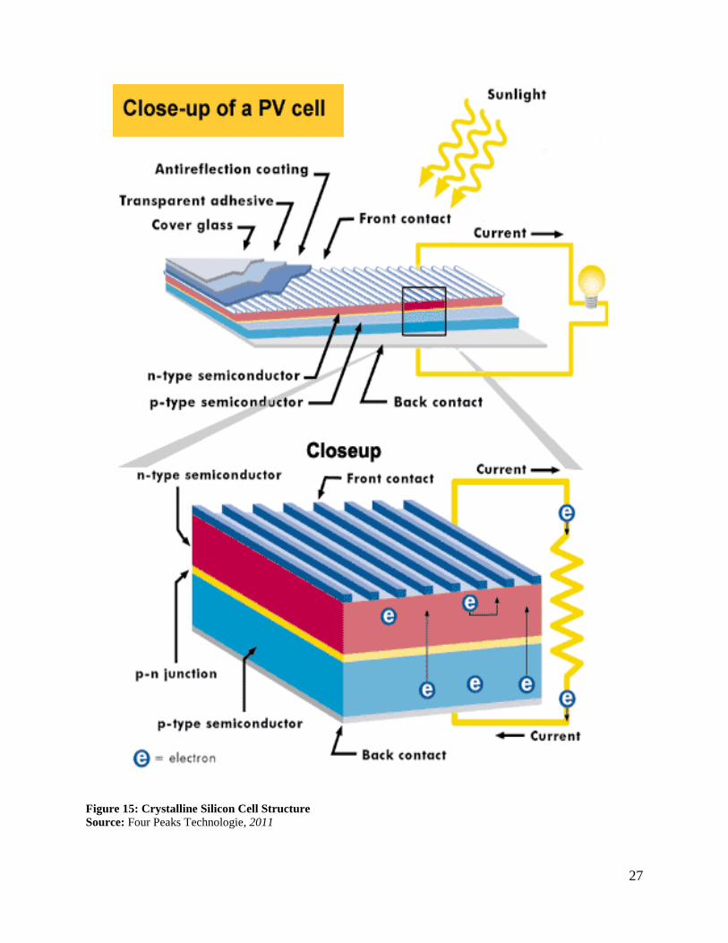
The first generation of PV technologies: crystalline silicon cells.
Silicon is one of the most abundant elements on the earth and it is very suitable for use in
photovoltaic systems. Depending on how silicon wafers are made, crystalline silicon cells
are divided into two general categories: mono-crystalline silicon and poly-crystalline
silicon. Other crystalline categories include gallium arsenide cells.
Second generation of PV technologies: Thin film solar cells.
After more than 20 years of research and development, thin film solar cells have started
to spread. Compared to silicon wafers, thin films reduced the cost of electricity quite
significant. Three main types of thin film solar cells, which have already been
commercialized, are:
o Amorphous silicon (aSi/µc-Si)
Page 26
26
o Cadmium telluride (Cd-Te)
o Copper–indium–selenide (CIS) and Copper- indium –gallium- selenide (CIGS)
The third generation of PV technologies: In development.
These technologies are still and still being developed and tested. They include:
o Concentrated photovoltaic (CPV)
o Organic solar cells
o Dye-sensitized solar cell
o Polymer solar cells
o Liquid-crystal solar cells
Page 27
27
Figure 15: Crystalline Silicon Cell Structure
Source: Four Peaks Technologie, 2011
Page 28
28
Figure 16: Layers of a solar cell
Source: Dako Power, cc 2008
5.1 Photovoltaic Systems Applications
Photovoltaic systems are applicable for public consumption and agriculture .It can be connected
to the power grid or works as stand-alone systems (autonomous) with the fixed or mobile
structure in small or large scale from providing energy required for small calculators to large
power plant. Possibility to track the sun and maximizing electricity generation from the sun light
during the day are the key advantages of using mobile system however due to the high risk of
failures in mechanical systems, using this technology for small and sporadic scale are not
recommended. This technology has been used only in few PV power plants around the worlds.
5.2 Methods for Using Photovoltaic Energy
Grid Connected
In this method, electrical energy from photovoltaic systems is transferred directly to the national
power grid. Voltage and frequency of the electrical energy produced by the photovoltaic system
can be adjusted to meet the voltage, frequency and phase characteristic of the national power grid
using electrical equipment to convert direct current (DC) to alternating current (AC), such as
inverters connected to the network and etc.)
Centralize/decentralize form of grid connected PV system boosts energy power of distribution
network (injected voltage and current prevents voltage drop of power distribution network during
the day.)
By implementing grid connected PV system, each member of national power grid represents as a
small distributed generation (DG).In addition to providing enough supply of electrical energy
required by the consumer; a consumer surplus can be injected to distributed network grid.
Page 29
29
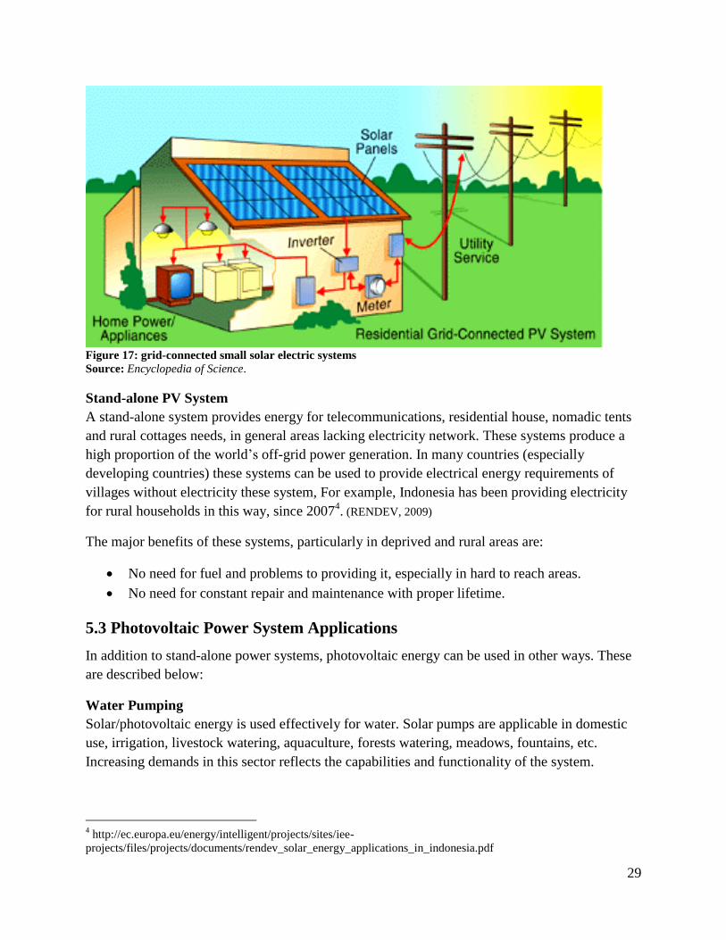
Figure 17: grid-connected small solar electric systems
Source: Encyclopedia of Science.
Stand-alone PV System
A stand-alone system provides energy for telecommunications, residential house, nomadic tents
and rural cottages needs, in general areas lacking electricity network. These systems produce a
high proportion of the world’s off-grid power generation. In many countries (especially
developing countries) these systems can be used to provide electrical energy requirements of
villages without electricity these system, For example, Indonesia has been providing electricity
for rural households in this way, since 20074. (RENDEV, 2009)
The major benefits of these systems, particularly in deprived and rural areas are:
No need for fuel and problems to providing it, especially in hard to reach areas.
No need for constant repair and maintenance with proper lifetime.
5.3 Photovoltaic Power System Applications
In addition to stand-alone power systems, photovoltaic energy can be used in other ways. These
are described below:
Water Pumping
Solar/photovoltaic energy is used effectively for water. Solar pumps are applicable in domestic
use, irrigation, livestock watering, aquaculture, forests watering, meadows, fountains, etc.
Increasing demands in this sector reflects the capabilities and functionality of the system.
4 http://ec.europa.eu/energy/intelligent/projects/sites/iee-
projects/files/projects/documents/rendev_solar_energy_applications_in_indonesia.pdf
Page 30
30
Figure 18: Application of solar water pumping system
Source: (Dr. Solar)
Solar Lighting Solar powered lighting can be used in residential
areas and schools, between road stations, tunnels,
marine lanterns, park lights, etc. The advantage of
this technology is providing light during the night
which is important factor for large and industrial
cities. Without access to electricity, lighting is
limited to oil lamps or dynamo lights. Solar lights
are a perfect solution for areas without access to
electricity for lighting. Tens of thousands of
examples of these systems are installed globally
every year.
Figure 19: Solar lighting
Source: Offthegrid, 2004
Portable Solar Generators
Portable Solar Generators, includings the solar vehicles, non-industrial electrical applications in
devices such as toys, solar calculators, etc. Ease of transportation and installation are the main
benefits of these systems, which plays an important role in its development.
Page 31
31
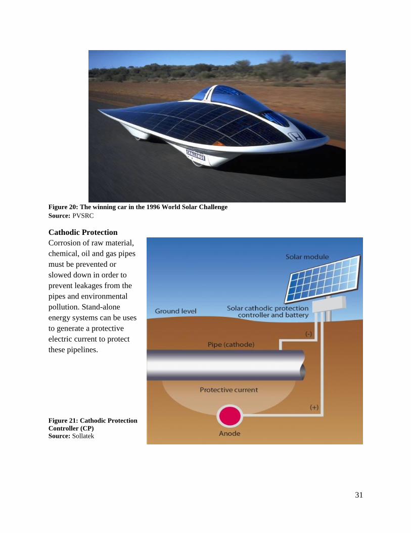
Figure 20: The winning car in the 1996 World Solar Challenge Source: PVSRC
Cathodic Protection
Corrosion of raw material,
chemical, oil and gas pipes
must be prevented or
slowed down in order to
prevent leakages from the
pipes and environmental
pollution. Stand-alone
energy systems can be uses
to generate a protective
electric current to protect
these pipelines.
Figure 21: Cathodic Protection
Controller (CP)
Source: Sollatek
Page 32
32
6. Global Solar Energy Statistics
6.1 Concentrating Solar Power (CSP)/Concentrated Solar Thermal (CST)
CSP and CST are CSP refer to technologies that use concentrated sunlight to heat up the receiver
and transform the heat to mechanical energy via turbine or other engines and then generate
electricity. (IEA)CPS and CST are used interchangelably .
The key feature of CST is that by storing solar energy it can discharge electricity to the grid at
the time that sun is not shining. The parabolic trough (PT) is the most common type of CST
systems, accounting for 90% of total installed CST technologies worldwide. (Probyn, 2012)
The high cost of investment causes increase in electricity cost and is one of the down sides of
this technology. In addition, to perform optimally, CST technologies require higher radiation
rates as compared with PV system. These technologies usually need water as a cooler, which is
often hard to find in locations with high solar accessibility.
Spain and United State are primary investors and also world leaders in the CST sector with
respectively about 1 GW and 500 MW installed, and more under construction or development.
Recently, developing countries have shown great interest in this technology due to their high
intensity of solar resources. For example, India plans to develop 500 MW of CST plants for the
Jawaharlal Nehru National Solar Mission in the first phase of the three-phase project. The South
African government awarded three CST concessions in December 2011 with total capacity of
200 MW. (Probyn, 2012) Other projects in developing countries include the
Thai Solar TSE1 and TSE2 plants in Thailand.
Solarium Mymensingh plant in Bangladesh (18 MW).
GeoBase Gwanda Solar Plant in Zimbabwe (120 MW)
Ouarzazate Solar phase 1 in Morocco (160 MW)
Page 33
33
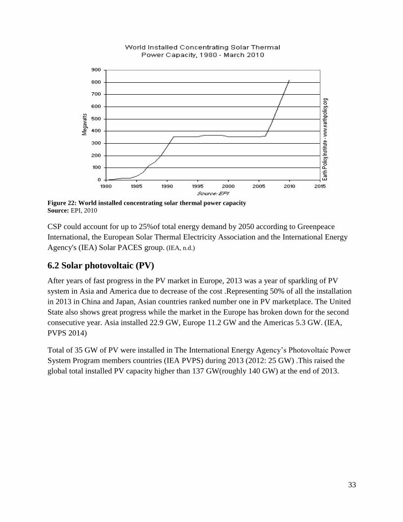
Figure 22: World installed concentrating solar thermal power capacity Source: EPI, 2010
CSP could account for up to 25%of total energy demand by 2050 according to Greenpeace
International, the European Solar Thermal Electricity Association and the International Energy
Agency's (IEA) Solar PACES group. (IEA, n.d.)
6.2 Solar photovoltaic (PV)
After years of fast progress in the PV market in Europe, 2013 was a year of sparkling of PV
system in Asia and America due to decrease of the cost .Representing 50% of all the installation
in 2013 in China and Japan, Asian countries ranked number one in PV marketplace. The United
State also shows great progress while the market in the Europe has broken down for the second
consecutive year. Asia installed 22.9 GW, Europe 11.2 GW and the Americas 5.3 GW. (IEA,
PVPS 2014)
Total of 35 GW of PV were installed in The International Energy Agency’s Photovoltaic Power
System Program members countries (IEA PVPS) during 2013 (2012: 25 GW) .This raised the
global total installed PV capacity higher than 137 GW(roughly 140 GW) at the end of 2013.
Page 34
34
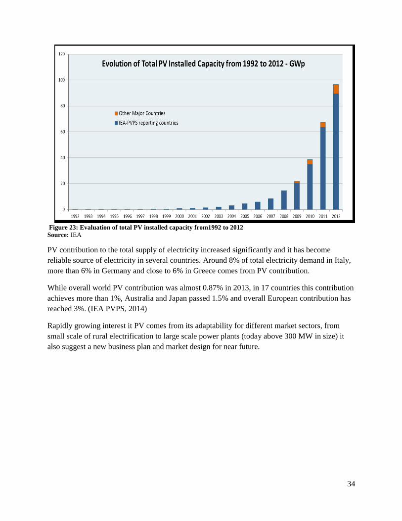
Figure 23: Evaluation of total PV installed capacity from1992 to 2012
Source: IEA
PV contribution to the total supply of electricity increased significantly and it has become
reliable source of electricity in several countries. Around 8% of total electricity demand in Italy,
more than 6% in Germany and close to 6% in Greece comes from PV contribution.
While overall world PV contribution was almost 0.87% in 2013, in 17 countries this contribution
achieves more than 1%, Australia and Japan passed 1.5% and overall European contribution has
reached 3%. (IEA PVPS, 2014)
Rapidly growing interest it PV comes from its adaptability for different market sectors, from
small scale of rural electrification to large scale power plants (today above 300 MW in size) it
also suggest a new business plan and market design for near future.
Page 35
35
7. Conclusion Statistics indicate that the production, conversion and consumption of different types of energy
are the main factors for destruction and pollution of the environment among the man-made
factors. However, not only the world's energy consumption will remain constant, but forecasts
indicate that consumption will continue growing due to increasing population, the desire for
prosperity and increasing per capita GDP (gross domestic product) in the world. (The World
Bank)
Consequences of energy consumption are increasing the amount of carbon dioxide emissions and
also SOX and NOX emissions. Studies show that there are two main solutions to mitigate this
issue:
Increasing energy efficiency
Increase the share of renewable energy in the global energy mix
For many years, the majority of the industry relies on fossil fuels (coal, oil and natural gas).
Fossil fuels are non-renewable resources that need for thousands of years to create, therefore,
fossil fuels cannot always respond to all human needs and sooner or later it will end.
So we must find an alternative to the fossil fuel. Solar energy can be a great alternative;
especially that it is a free and unlimited source. It will help us to have clean and sustainable
energy to power our world whiteout any damage to our environment. It will help us to have zero
dependency on costly and damaging fossil fuel. There is no doubt that as future solar power
technology costs continue to decline, fossil fuel costs will dramatically increase.
So attention must be focused on renewable energies as a low risk investments and solar energy
becomes the preferred target of investors.
Page 36
36
8. Bibliography
A.K.Karthikeyan. (2013, February 25). Solar dryer. Retrieved from wikipedia:
http://en.wikipedia.org/wiki/Solar_dryer%29
Aghaei, T. P. (2015). Potential for small solar water pasteurizer techniques for water
disinfection in rural area of developing countries. San Diego.
Alternative Energy Tutorials. (n.d.). Solar Pool Heating. Retrieved from Alternative Energy
Tutorials: http://www.alternative-energy-tutorials.com/solar-hot-water/solar-pool-
heating.html
AndrewBuck. (2008, February 16). Parabolic trough. Retrieved from Wikipedia:
http://en.wikipedia.org/wiki/Parabolic_trough#mediaviewer/File:Parabolic_trough.svg
ASME. (2012). Solar thermal power plants. Retrieved from volker-quaschning.de:
http://www.volker-quaschning.de/articles/fundamentals2/index_e.php
Canivan, J. (n.d.). Trickle Down Solar Heating. Retrieved from Solar Homes & Solar Collectors:
http://www.jc-solarhomes.com/trickle_down_solar.htm
Dako Power cc. (2008). Solar Basics Explained. Retrieved from Dako power:
http://www.dako.co.za/solar_basics.html#
DOE/NREL. (2000, january). Solar Multimedia. Retrieved from US Department of energy:
https://www.eeremultimedia.energy.gov/solar/graphics/linear_fresnel_power_plant_illust
ration
Dr. Solar. (n.d.). Solar Water Pumping System India. Retrieved from tumblr.com:
https://www.tumblr.com/search/Solar+Water+Pumping+Systems+Bangalore
Encyclopedia of Science. (n.d.). grid-connected small solar electric systems . Retrieved from
The Worlds of David Darling • Encyclopedia of Science:
http://www.daviddarling.info/encyclopedia/S/AE_small_solar_electric_systems_grid-
connected.html
EPI. (2010, 3 11). Plan B 4.0 by the Numbers – Solar Energy . Retrieved from Earth Policy
Institute: http://www.earth-policy.org/data_highlights/2010/highlights9
Evans, D. L., & Evans, J. &. (2007 ). passive solar heating. Retrieved from The Complete Real
Estate Encyclopedia: http://financial-
dictionary.thefreedictionary.com/passive+solar+heating
Extension, P. S. (n.d.). Solar Energy . Retrieved from Penn State Extension/College of
Agricultural Sciences: http://extension.psu.edu/natural-resources/energy/solar-energy
Page 37
37
Four Peaks Technologies. (2011). Solar in-depth. Retrieved from Solar Cell Central:
http://solarcellcentral.com/index.html
IEA. (n.d.). 2012. International energy Agency.
IEA. (n.d.). Concentrated solar power could generate 'quarter of world's energy' . Retrieved
from The Guardian: http://www.theguardian.com/environment/2009/may/26/solarpower-
renewableenergy
IEA PVPS. (2014). Trends in Photovoltaic Applications. Paris: The International Energy
Agency’s Photovoltaic Power System Programme .
IEA. (n.d.). Solar (PV and CSP). Retrieved from International Energy Agency:
http://www.iea.org/topics/solarpvandcsp/
iSuppli, I. (2013, December 11). Concentrated photovoltaic sollar installations set to boom in
the coming years. Retrieved from http://itersnews.com: http://itersnews.com/?p=61153
Jha, A. (2010, July 20). E=mc2 . Retrieved from Aniket:
http://aniketjha.blogspot.com/2010/07/emc2.html
love4earth. (n.d.). Stirling Power Plant. Retrieved from Our Home Our Planet:
http://love4earth.es.tl/STIRLING-POWER-PLANT.htm
Morton, O. ( 2006, September 7 ). Solar energy: A new day dawning?: Silicon Valley sunrise.
Retrieved from Nature.com:
http://www.nature.com/nature/journal/v443/n7107/full/443019a.html#top
NASA. (n.d.). Advanced Energy Research.photovoltaic. Retrieved from grc.nasa.gov:
http://www.grc.nasa.gov/WWW/portal/apps/pv/
NASA. (n.d.). Solar System Exploration. Retrieved june 20, 2014, from Natural Aerounatics and
Space Administration: http://solarsystem.nasa.gov/planets/profile.cfm?Object=Sun
nave, R. (2000, August). Proton-Proton Fusion . Retrieved from hyperphysics/Georgia State
University: http://hyperphysics.phy-astr.gsu.edu/hbase/astro/procyc.html
NESTA, N. E. (n.d.). Fusion Reactions. Retrieved from Windows to the Universe:
http://www.windows2universe.org/sun/Solar_interior/Nuclear_Reactions/Fusion/fusion_r
eactions.html
offthegrid. (2004, june2 2). People Really Seem To Like Outdoor Solar Lights. Retrieved from
Start Living Off the Grid : http://startlivingoffthegrid.net/people-outdoor-solar-lights/
Page 38
38
Parish, R. (n.d.). The History of Solar. Retrieved from US Department of energy/energy
efficiency and renewable energy:
https://www1.eere.energy.gov/solar/pdfs/solar_timeline.pdf
Probyn, J. (2012, November 26). Is Concentrated Solar Thermal Making Progress in Developing
Countries? Retrieved from The World Bank: http://blogs.worldbank.org/energy/is-
concentrated-solar-thermal-making-progress-in-developing-countries
PVSRC. (n.d.). High Efficiency Solar Cells. Retrieved from PV Education.org:
http://pveducation.org/pvcdrom/manufacturing/high-efficiency
RENDEV. (2009). reinforcing provision of sustainable energy service in Bangladesh and
Indonesia for poverty alleviation and sustainable development. Indonesia: inteligent
energy Europe.
Renewable Energy World. (2003, june). Renewable Energy World. Retrieved from Solar thermal
power plants, Technology Fundamentals:
http://solarenergyengineering.asmedigitalcollection.asme.org/article.aspx?articleid=1662
250
Ryan, V. (2005). Applications of solar thermal power plants. Retrieved from technologystudent:
http://www.technologystudent.com/energy1/solar4.htm
SEIA. (n.d.). Photovoltaic (Solar Electric). Retrieved from Solar Energy Industries Association:
http://www.seia.org/policy/solar-technology/photovoltaic-solar-electric
Solar fred. (2010, April 13). Solar Thermal 101: Flat Plate Solar Collectors. Retrieved from
freehotwater solar thermal solution: http://www.freehotwater.com/solar-thermal-101-flat-
plate-solar-collectors/
Solar PACES. (n.d.). eskom/powering your world. Retrieved from
http://www.eskom.co.za/AboutElectricity/RenewableEnergy/ConcentratingSolarPower/P
ages/How_Does_It_Work.aspx
Sollatek. (n.d.). Cathodic Protection Controller (CP). Retrieved from Sollatek:
http://www.sollatek.com/products/cathodic-protection-controller-cp/
suna.org.ir. (n.d.). Renewable energy, solar energy, Retrieved on August23, 2014,. Retrieved
from http://www.suna.org.ir
sunvelope. (2011, October). Solar Water Heater. Retrieved from http://www.sunvelope.com/wp-
content/uploads/2011/10/swh_diagram.png
TCS Power. (n.d.). Dish stirling systems. Retrieved from TCS Power: http://www.tcs-
power.eu/media-center.html
Page 39
39
Terra Fundacion. (n.d.). Solar fruit dryer. Retrieved from cocinsolar: http://www.solar-
cooker.org/cookers/solar-fruit-dryer
The World Bank. (n.d.). GDP per capita (current US$) . Retrieved from The World Bank:
http://data.worldbank.org/indicator/NY.GDP.PCAP.CD/countries?display=map%25%25
2020
Vickery, D. (2014, June). Solar Ovens, Panel Cookers, and Parabolic Solar Cookers. Retrieved
from One Earth Design: https://www.oneearthdesigns.com/blog/solar-ovens-panel-
cookers-parabolic-solar-cookers/
Page 40
40
Appendix
General Knowledge about the Sun
• The sun is made of gas which is most sensitive to the magnetic force, called plasma.
• The Sun’s radius (distance from the center to its surface), is about 695.500 kilometers,
roughly 109 times the radius of the Earth.
• The sun has a surface temperature of 5800 K (9980.3o F). The solar core temperature is
more than 15 million degree Kelvin (2.7000e+7º F).
• The sun mass is 99.8% of the total mass of the Solar System, which is 333,000 times the
mass of Earth.
• The average density of sun is about 90 pounds per cubic foot, or about 1.4 grams per
cubic centimeter. This value is about 1.4 times the density of water and less than a third
the average density of the earth.
• Like most of stars, the majority of the atoms of the Sun, are from the chemical element of
hydrogen. After hydrogen, helium is the most common element found in the sun. The rest
of the mass of the sun is composed of atoms of seven other elements. There are 98,000
atoms of helium, 850 atoms of oxygen, 360 atoms of carbon, 120 atoms of neon, 110
atoms of nitrogen, 40 atoms of magnesium, 35 atoms of iron and 35 atoms of silicon in
the sun for every1 million atoms of hydrogen. So about 94 percent of the atoms are
hydrogen and 0.1% of them are other than hydrogen and helium.
• The mass of the lightest element of the sun, hydrogen is about 73.46 percent, 24.85
percent helium, 0.77% oxygen , 0.29% carbon, 0.16 % iron, 0.12 % sulfur, .12% neon,
0.09% nitrogen, 0.07% silicon, and 0.05% magnesium of the total mass of the sun.
• According to scientific estimation, about 4.5 million years since the birth of this fireball
has been passed and up to next 5 billion years from now, it can still be regarded as a great
source of energy.
• Due to reflection, scattering and absorption by gases and aerosols in the atmosphere, only
47% of the energy of the sun reaches the Earth's surface.
• The total solar energy absorbed by Earth's atmosphere, oceans and land masses is
approximately 3,850,000 exajoules (EJ) per year.