15
Solar Power System Installation Manual Power-Save Energy Co. 3940-7 Broad St. #200 San Luis Obispo, CA 93401 866 297 7192
| Date post: | 08-Nov-2014 |
| Category: |
Documents |
| Upload: | singam-sridhar |
| View: | 21 times |
| Download: | 2 times |
Solar Power SystemInstallation Manual
Power-Save Energy Co. 3940-7 Broad St. #200 San Luis Obispo, CA 93401 866 297 7192

FOR INSTALLATION PERSONNEL
• Please read this manual carefully before installing the system and carry outthe installation procedures correctly.
• This manual does not list all precautions needed for safe work. Be sure tofollow OSHA guideline.
• This manual provides guidelines for installation, but it does not guaranteethe quality of installation work. Please complete all work in a responsible andprofessional manner. Electrical work should be performed by a qualifiedelectrician.
1 FOR SAFE INSTALLATION WORKThe system should be installed only by individuals who have training orprevious experience installing PV Systems. All required licenses andcertifications as well as safety standards must be adhered to.
WARNING• Do not cut or modify Mounting System. Doing so is dangerous. Safetycannot be guaranteed.• Do not work during stormy weather. Solar modules can be caught in thewind, causing you to fall.
CAUTION• Never step or sit on the glass surface of a solar module. The glass maybreak, resulting in shock or bodily injury. The module may also stopgenerating power.• Always use the supplied parts to attach the solar modules and mounts. Use of weaker parts, such as screws that are too short, is dangerous andmay cause the solar modules or mounts to fall.• Always use the specified tools. The solar modules or mounts may fall if theinstallation is not strong enough, for example when parts are not tightenedsufficiently.• Regardless of whether you are working on a new or existing roof, neverallow the sheathing to become wet. Protect the sheathing from rain during theinstallation. Failure to do so may cause leaks.• Always use the specified materials. Use of other materials is dangerous.Materials other than specified can reduce performance and can cause leaks,shock, and so on.• Do not modify or cut parts.• Do not install in corrosive locations classified C5 by ISO.• Protective earth grounding of the individual photovoltaic modules is achievedby securing the modules to the mounting frames. The assembly instructionsshould be closely followed, in order to ensure a reliable ground connection.

UL REQUIRED INFORMATION:
1. Artificially concentrated sunlight shall not be directed on the module.
2. “Rated electrical characteristics are within 10 percent of measured valuesat Standard Test Conditions of: 1000 W/m2, 25°C cell temperature and solarspectral irradiance per ASTM E 892 or irradiation of AM 1.5 spectrum.”
3. Under normal conditions, a photovoltaic module may experience conditionsthat produce more current and/or voltage than reported at Standard TestConditions. Accordingly, the values of ISC and VOC marked on UL Listedmodules should be multiplied by a factor of 1.25 when determining componentvoltage ratings, conductor capacities, fuse sizes and size of controlsconnected to the module output. Refer to Section 690-8 of the NationalElectric Code for an additional multiplying factor of 1.25 which may beapplicable.
4. Wiring methods should be in accordance with the NEC.
5. Install wires and cables with appropriate hardware in accordance withapplicable electrical codes.
6. Protective earth grounding of the individual photovoltaic modules isachieved by securing the modules to the mounting frames. The assemblyinstructions should be closely followed, in order to ensure a reliable groundconnection.
7. The framing system shall be grounded in accordance with NEC Article 250.
8. #10 AWG copper wire is the minimum size acceptable for the primaryprotective ground connection to the rails.
9. A UL Listed Grounding terminal constructed of tin-plated copper orstainless steel, or steel provided with a zinc or beryllium coating, and suitablefor outdoor use, shall be used with the selected grounding wire (minimum 10AWG copper wire).
10. All of the Rails in an installation shall be provided with protective earthbonding wires when installed.
11. The framing system has only been evaluated by UL for use with thephotovoltaic modules listed in this manual.
1.1 CAUTIONS REGARDING INSTALLATION OF SOLAR POWER

SYSTEMSThis manual contains critical information regarding electrical and mechanicalinstallation and safety information that you should know before startinginstallation.
Do not locate systems near coastal locations or other saltwater locations orC5 locations as classified by ISO. Minimum distance is 0.3 miles from thebody of water.
Do not locate in a corrosion prone area. The modules and system are ULlisted to standard 1703. The UL 1703 test is performed at 1.5 times the designload of 30 lbs per square foot, or 45 lbs per square foot.
CAUTION1. Do not drill holes in frame. Do not cut or modify parts or rails.2. Work under dry conditions with dry tools.3. Do not stand or step on solar module.4. Do not install near flammable gases.5. Do not drop or allow objects to fall onto module.6. Completely cover solar module with opaque materials when wiring to
halt production of electricity.7. Keep the backside of solar module surfaces free of foreign objects.8. Do not use chemicals on solar modules when cleaning.9. Do not wear metallic jewelry, which may cause electrical shock.10. Do not touch cable electrical contacts.11. Do not expose solar modules to sunlight that is concentrated with
mirrors, lenses or similar means.12. Consult local codes and other applicable laws and statutes concerning
required permits and regulations concerning installation and inspectionrequirements. Install solar modules and systems according toapplicable codes.
13. Product should be installed and maintained by qualified personnel.Keep unauthorized personnel away from solar modules.
14. Avoid shadowing cells in order to prevent solar module hot spotsand/or reduction in power.
15. Avoid installing modules and mounting system in high corrosion areas.
1.2 PV MODULESWARNING: Wiring work should be performed according to the provisions ofthe National Electrical Code. The grounding work and wiring connections tothe inverter should be performed by a qualified electrician.
Adhere to all NEC. Pay special attention to Article 110, Chapter 2, Article 250,Chapter 3, Articles 300 & 310, 480 & 690.
The solar array generates electricity whenever it is exposed to sunlight. Becareful when handling it. There is a danger of shock if you touch the
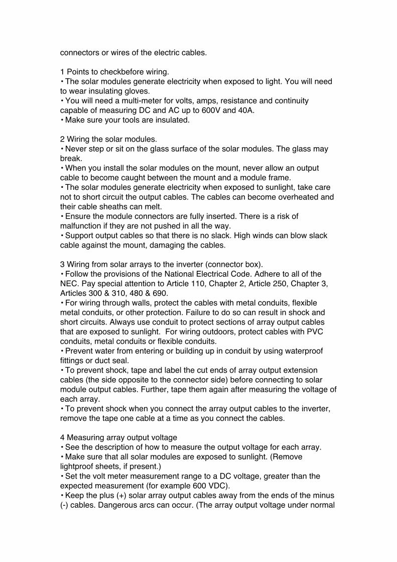
connectors or wires of the electric cables.
1 Points to checkbefore wiring.• The solar modules generate electricity when exposed to light. You will needto wear insulating gloves.• You will need a multi-meter for volts, amps, resistance and continuitycapable of measuring DC and AC up to 600V and 40A.• Make sure your tools are insulated.
2 Wiring the solar modules.• Never step or sit on the glass surface of the solar modules. The glass maybreak.• When you install the solar modules on the mount, never allow an outputcable to become caught between the mount and a module frame.• The solar modules generate electricity when exposed to sunlight, take carenot to short circuit the output cables. The cables can become overheated andtheir cable sheaths can melt.• Ensure the module connectors are fully inserted. There is a risk ofmalfunction if they are not pushed in all the way.• Support output cables so that there is no slack. High winds can blow slackcable against the mount, damaging the cables.
3 Wiring from solar arrays to the inverter (connector box).• Follow the provisions of the National Electrical Code. Adhere to all of theNEC. Pay special attention to Article 110, Chapter 2, Article 250, Chapter 3,Articles 300 & 310, 480 & 690.• For wiring through walls, protect the cables with metal conduits, flexiblemetal conduits, or other protection. Failure to do so can result in shock andshort circuits. Always use conduit to protect sections of array output cablesthat are exposed to sunlight. For wiring outdoors, protect cables with PVCconduits, metal conduits or flexible conduits.• Prevent water from entering or building up in conduit by using waterprooffittings or duct seal.• To prevent shock, tape and label the cut ends of array output extensioncables (the side opposite to the connector side) before connecting to solarmodule output cables. Further, tape them again after measuring the voltage ofeach array.• To prevent shock when you connect the array output cables to the inverter,remove the tape one cable at a time as you connect the cables.
4 Measuring array output voltage• See the description of how to measure the output voltage for each array.• Make sure that all solar modules are exposed to sunlight. (Removelightproof sheets, if present.)• Set the volt meter measurement range to a DC voltage, greater than theexpected measurement (for example 600 VDC).• Keep the plus (+) solar array output cables away from the ends of the minus(-) cables. Dangerous arcs can occur. (The array output voltage under normal

conditions (clear skies) can be very high.)
5 Grounding the mount• To prevent shock, always connect a ground wire from the mountinghardware to earth.• Use a minimum #10 AWG ground wire. Run a continuous bond wire to eachmodule and rail in the array. Refer to section on grounding in this manual.• Follow NEC 690 grounding provisions.
2 POINTS TO CHECK WHEN SELECTING THE INSTALLATIONLOCATIONCheck the following items before starting installation work. Refer to theinverter installation manual for more information about inverter installation andelectrical work.
2.1 CONDITION OF HOUSE WHERE SOLAR POWER SYSTEM IS TOBE INSTALLED
INSPECTION OF ROOF STRUCTUREIt is important to inspect the structural integrity of the roof and the durability ofthe roof materials. The SRS mounting structure and solar modules require astrong base for durable and reliable operation in local environments. Alwayswear a safety harness when working on the roof.
Inspect the roof surface in the area of the installation for cracks, waterleakage, and roofing material quality and uniformity. This is especiallyimportant if the roof is older than10 years.
Inspect the roof for sags and other abnormalities. A sag or deep depression inthe roof may indicate a structural weakness in the support system that mayrequire correction. The following illustrations detail typical roof construction aswell as old roof problems.
INSPECTION OF THE ROOF SUPPORT SYSTEMThis may require access to the attic. Check that all rafters, trusses and othermaterials are in good condition. Check for indication of previous water leaks.Measure the spacing of the rafters or trusses to confirm the dimensions andprepare for the system layout. Determine the location of the electrical roofpenetration and wire run, if wiring is planned for this area.
1. Install solar modules facing south, if possible. Installations facing east andwest are also possible, although the amount of power generated will be lower.Check the roof from a southern orientation, and check for obstacles that willcast a shadow. These factors will lower the amount of power generated.Explain this to the users and obtain their consent.
2. Install in a location that has good sun exposure throughout the year. Lesspower is generated in shaded locations.

3. Check the following before installation.
3.1 Solar modules should not be installed within 12" from the ridge oredges of the roof, nor within 16" from the eave.
3.2 Installation is not possible in regions where the wind pressureexceeds 45 PSF. Check with your local building department to determine ifthis mounting system is in compliance. Installation is not possible when theroof angle is less that 10 degrees or greater than 45 degrees.
3.3 Do not locate systems near coastal locations or other saltwaterlocations or C5 locations as classified by ISO. Minimum distance is 0.3 milesfrom the body of water. The array must be installed at least 16" away from theeave of the roof and 12" from the sides of the roof. This border will enhancethe wind load resistance of the system.
4. The output of a series string of solar modules is connected to the input ofthe inverter. Always install solar modules so that all elements of the arrayreceive the same amount of sunlight. The amount of power generateddeclines dramatically if you connect solar modules receiving different amountsof light in a string array, for example, solar modules facing east and solarmodules facing south should not be connected in the same string. Refer tothe inverter installation manual for more information about the number of solarmodules connected in series in a single array.
5. It may not be possible to install solar modules in the following areas andunder the following conditions. For more information, contact technicalsupport.
• Regions with heavy snowfall - Installation is not possible in regions wheresnow accumulation exceeds the maximum allowable load. Contact thebuilding department for more information about maximum snow accumulation.

3 PARTS
Accessory List
Item # Descriptions PCS / Kit
L-Feet 16
3/8-16*7/8 screw 161
3/8 screw nut 16
Mid clamps 8
1/4-20*2-1/4 screw 82
1/4 screw nut 8
splice kit 4
3/8-16*7/8 screw 163
3/8 screw nut 16

End clamps 8
1/4-20*3/4 screw 84
1/4 screw nut 8
ground lug 65
1/4-20*16 screw 6
6 51_length rack 8
Total 152
5. Ground Lug 6. Rail 1. L Feet 4. End Clamp 2. Mid Clamp
3. Splice kit
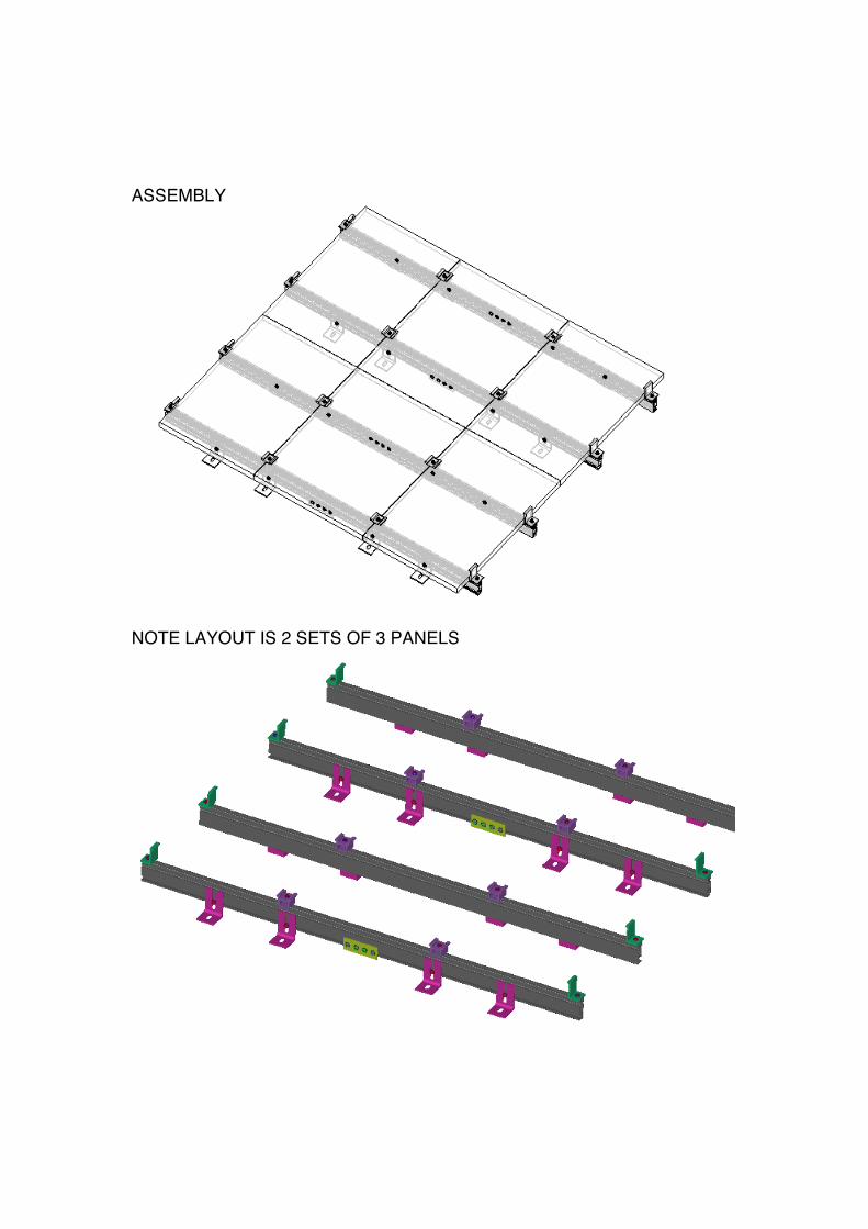
ASSEMBLY
NOTE LAYOUT IS 2 SETS OF 3 PANELS

4 POINTS TO CHECK BEFORE INSTALLATION WORK
WARNING• The solar modules generate electricity when exposed to sunlight, so becareful not to short circuit the output cables. The cables can becomeoverheated and their cable sheaths can melt. • Stop working when thesurface of the roof is wet. There is a danger of slipping, falling, and shock.
CAUTION• Never step or sit on the glass surface of the solar modules. The glass maybreak.• Do not twist the solar modules when you mount them (twisting should notexceed 0.1" per 4"). Failures and damage can result.• When you mount the solar modules on the rail, never allow an output cableto become caught between the rail and a module frame. Short circuits and firecan result.
4.1 UNPACKING AND CHECKING PARTSWhen you unpack the system, check the model names of the components ofeach system and check to be sure that you have the correct number of parts.
4.2 MATERIALS AND TOOLS YOU WILL NEEDBefore starting installation work, make sure you have the following materialsand tools on hand (including materials and tools for electrical work).
MATERIALSGround wire, Ground Rod Electrical tapeFlexible metal conduit (to protect electric cables)Cable tiesPencilCordless drillSocket driversPhillips driver bitsDrillScrewdriver setNeedle nose pliersLineman’s pliersWire cuttersHammer ChiselCrimping toolKnifeTape measureExtension cord

Chalk lineGloves & safety helmetRope Tool belt Ladders Safety HarnessCompassCalculatorSolar insulation meterDigital multi-meter
5 INSTALLATION WORK
5.1 PREPARING SHINGLE / COMPOSITE ROOF FORINSTALLATION1. Locate roof rafters or trusses. Tip: here are 3 options to finding thelocations.
A. Locate and measure the locations of the rafters in the attic or at theoutside eave and transfer measurements to the roof.
B. Use a rubber or leather mallet to tap the roof and locate the rafters.This will work with a cap sheet or composition roof.
C. Scan the roof with a high sensitivity stud finder.
2. Once the rafters have been located, snap a chalk line on every rafter toidentify the location.
3. Measure up from the eave 16" (400 mm) in at least 3 locations. Snap achalk line. This marks the location of the bottom edge of the slider feet. Note:This line needs to be 0.22" (5.5 mm) away from the nearest front edge ofshingles.
4. Measure up from chalk line 0.8" (20 mm) and snap a new chalk line. Thismarks the location of the bottom edges of the modules.
5. Measure up from the module chalk line to the desired module length toform the array. Snap horizontal lines at the measured locations.
6. Mark and layout solar module vertical lines. Note: modules should not fallin shaded areas.

LAYING OUT L-FEETL-feet (Fig. above) are used for installation through existing roofing material,such as asphalt shingles or sheet metal. In low-profile layouts, stagger feeton rafters (Fig. above) to distribute the load.
Installing L-feetDrill pilot holes through the roof into the center of the rafter at each L-foot lagbolt hole location.
Lag bolts are not provided with Solar Mount rail sets.
Apply sealant into the hole, and on the shafts of the lag bolts. Seal theunderside of the L-feet with a suitable weatherproof sealant.
Securely fasten the L-feet to the roof with the lag bolts. Ensure that the L-feetface as shown in Figure above. The single-slotted square side of the L-footmust always lie against the roof with the double-slotted side perpendicular tothe roof.
INSTALLING RAILSKeep rail slots free of roofing grit or other debris. Foreign matter will causebolts to bind as they slide in the slots.
Installing Splices. If your installation uses solar splice bars, attach the railstogether (Fig. below) before mounting the rails to the footings. Use splicebars only with flush installations.

MOUNTING RAILS ON L-FEETRails may be attached to either of two mounting holes in the L-Feet (Fig.below). Mount in the lower hole for a low profile, more aesthetically pleasinginstallation. Mount in the upper hole for a higher profile, which will maximizeairflow under the modules. This will cool them more and may enhanceperformance in hotter climates. Slide the 3⁄8-inch mounting bolts into thefooting bolt slots. Loosely attach the rails to the footings with the flange nuts.Align one pair of rail ends to the edge of the installation area.
INSTALLING THE MODULESIf modules have standard J-boxes, each module should be pre-wired with oneend of the inter-module cable for ease of installation. For safety reasons,module pre-wiring should not be performed on the roof. Leave covers off J-boxes. They will be installed when the modules are installed on the rails.
1.1 Installing the First Module.In low-profile installations, the safety bolt and flange nut must be fastened tothe module bolt slot at the aligned (lower) end of each rail. It will prevent thelower end clamps and clamping bolts from sliding out of the rail slot duringinstallation.
If there is a return cable to the inverter, connect it to the first module. Closethe J-box cover. Secure the first module with T-bolts and end clamps at thealigned end of each rail. Allow half an inch between the rail ends and the end

clamps. Finger tight the flange nuts, center and align the module as needed,and then securely tighten the flange nuts
1.2 Installing the Other Modules.Lay the second module face down (glass to glass) on the first module.Connect inter-module cable to the second module and close the J-box cover.Turn the second module face up. With T-bolts, mid clamps, and flange nuts,secure the adjacent sides of the first and second modules. Align the secondmodule and securely tighten the flange nuts.
For a neat installation, fasten cable clamps to rails with self-tapping screws.Repeat the procedure until all modules are installed. Attach the outside edgeof the last module to the rail with end clamps.
Trim off any excess rail, being careful not to cut into the roof. Allow half aninch between the end clamp and the end of the rail. Check that all flangenuts on T-bolts are securely fastened.
5.2 SYSTEM GROUNDINGUpon completion of the array ground wire, bring to the rooftop junction box.Use at least a 10 AWG ground wire for this purpose. The ground will continuedown to the DC disconnect and to the inverter. The inverter must be groundedto a ground rod. All of the Rails in an installation shall be provided withprotective earth grounding wires when installed.
Accomplishing a code compliant grounding system is critical to the safety ofthe system. Continuous grounding of all modules and mounting systemcomponents is required.
1. Install outdoor rated ground lugs or ring terminals with ground wire. Use themarked ground hole on either end of the rail.2. Connect a minimum # 10 AWG solid conductor, copper, ground wire to theground lug or ring terminal.3. Land the end of the ground wire in the array junction box.4. Run the ground wire to the DC disconnect and inverter.5. Run the ground wire from the inverter to a ground rod.
INSTALL INVERTER AS PER INVERTER INSTRUCTIONS


