21
Solar power station – an element of dispersed power system Wroclaw Division of Electrotechnical Institute; Wroclaw University of Technology, Dep. of Electrical Eng. Bolesław Mazurek
Solar power station – an element of dispersed power system
Wroclaw Division of Electrotechnical Institute;Wroclaw University of Technology, Dep. of Electrical Eng.
Bolesław Mazurek
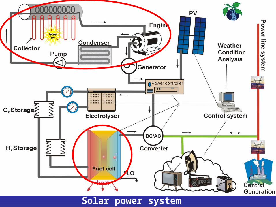
Solar power system

T-s Diagram of Rankine cycle
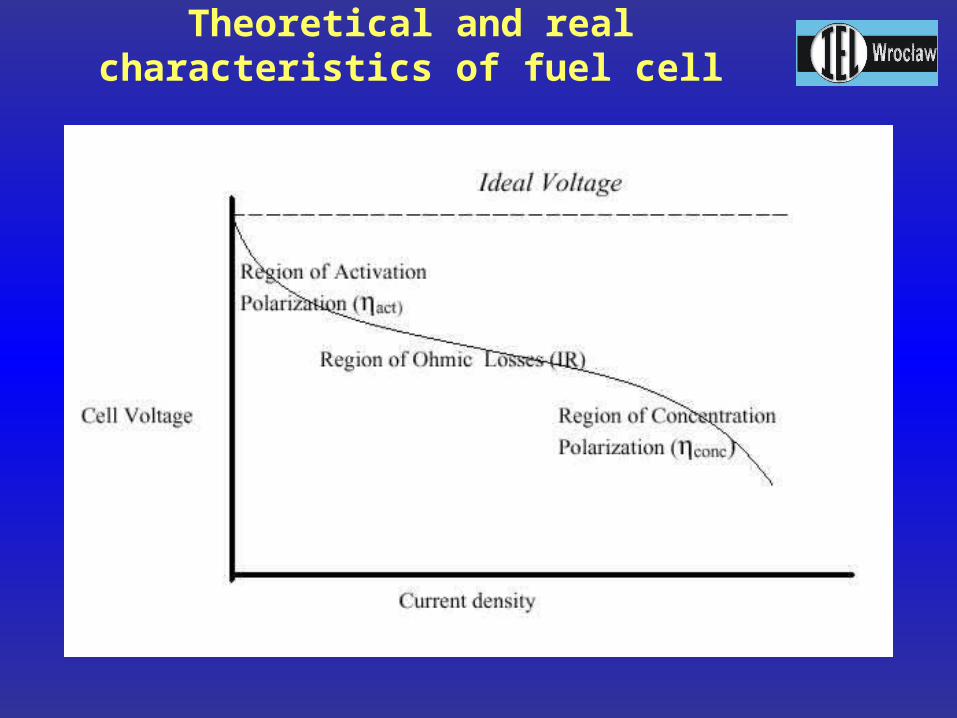
Theoretical and real characteristics of fuel cell

Vehicle mechanism
oxygen
oxygen in the middle ion H3O
hydrogen
H2O
H3O

PEM Fuel Cellreactions:
Cathode reaction:O2 + 4H+ + 4e- 2H2O
Anode reaction:2H2 4H+ + 4e-
Summary raction:2H2 + O2 2H2O
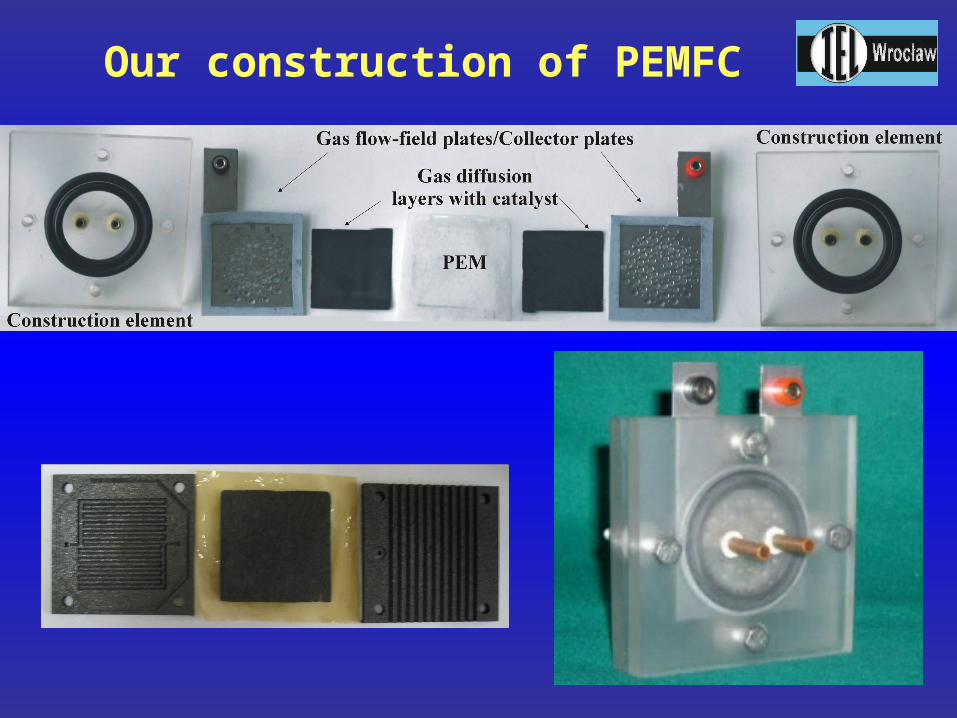
Our construction of PEMFC

V-I characteristics of IEL and commercial PEMFC
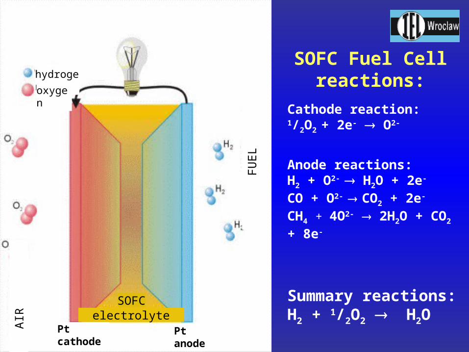
SOFC Fuel Cellreactions:
Cathode reaction:1/2O2 + 2e- O2-
Anode reactions:H2 + O2- H2O + 2e-
CO + O2- CO2 + 2e-
CH4 + 4O2- 2H2O + CO2 + 8e-
Summary reactions:H2 + 1/2O2 H2O
A
IR
F
UE
L
hydrogen
oxygen
Ptcathode
Ptanode
SOFC electrolyte

New electrolytes elaborated in
IEL/OW for SOFC application
Chemical formula Name
Bi2V0,75Cr0,25O5,25 - BIMEVOX
Bi2V0,9Sb0,1O5,4 - BIMEVOX
Bi2V0,9Co0,1O5,4 BICOVOX family
Bi2V0,875Ti0,125O5,4375 BIMEVOX family
Bi2V0,86Zn0,1O5,25 BIMEVOX family
Bi2V0,73Zn0,27O5,095 BIZNVOX.27
Bi2V0,9Cu0,1O5,35 BICUVOX.10
Bi4V2O11 BIVOX family
Bi4V1,9Co0,1O10,85 BIVOX family
Bi4V1,8Co0,2O10,7 BIVOX family
Bi2Co0,1V0,9O5,35 BIVOX family
(Bi0,95Zr0,05O1,525)0,8(YO1,5)0,2 stabilizowany -Bi2O3
Bi4V1,95Fe0,05O10,95 BIMEVOX family
Bi4V1,9 Fe 0,1O10,9 BIMEVOX family
Bi4V1,8Fe0,2O10,8 BIMEVOX family
Bi4V1,5Fe0,5O10,5 BIMEVOX family
Bi4V1,75Fe0,25O10,75 BIMEVOX family
Bi4V1,7Fe0,3O10,7 BIMEVOX family
(Bi0,95Zr0,05O1,525)0,85(YO1,5)0,15
(Bi0,98Zr0,02O1,51)0,85(YO1,5)0,15
(Bi0,90Zr0,10O1,55)0,85(YO1,5)0,15
(Bi0,90Zr0,10O1,55)0,8(YO1,5)0,2
Also investigation ofscandium stabilized zirconium oxide(e.g. ScSZ)

Ionic conductivity measurements
Fig.1 Diagram of the system for measurement of the ionic conductivity, DC four probe Wagner method.
Fig.2 Diagram of the test stand for measurement of the ionic conductivity, IS impedance spectroscopy method.

Typical Arhenius characteristics of electrolytes
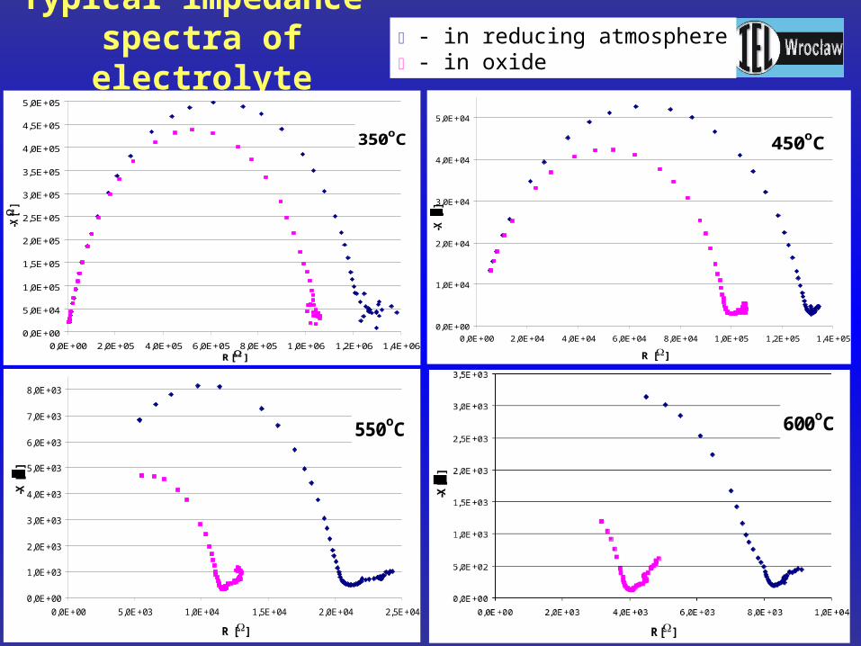
Typical impedance spectra of electrolyte
350oC
0,0E+00
5,0E+04
1,0E+05
1,5E+05
2,0E+05
2,5E+05
3,0E+05
3,5E+05
4,0E+05
4,5E+05
5,0E+05
0,0E+00 2,0E+05 4,0E+05 6,0E+05 8,0E+05 1,0E+06 1,2E+06 1,4E+06R[ ]
-X[
]
450oC
0,0E+00
1,0E+04
2,0E+04
3,0E+04
4,0E+04
5,0E+04
0,0E+00 2,0E+04 4,0E+04 6,0E+04 8,0E+04 1,0E+05 1,2E+05 1,4E+05
R []
-X [
]550oC
0,0E+00
1,0E+03
2,0E+03
3,0E+03
4,0E+03
5,0E+03
6,0E+03
7,0E+03
8,0E+03
0,0E+00 5,0E+03 1,0E+04 1,5E+04 2,0E+04 2,5E+04
R []
-X [
]
- in reducing atmosphere - in oxide

Our tubular SOFC
0
100
200
300
400
500
600
700
800
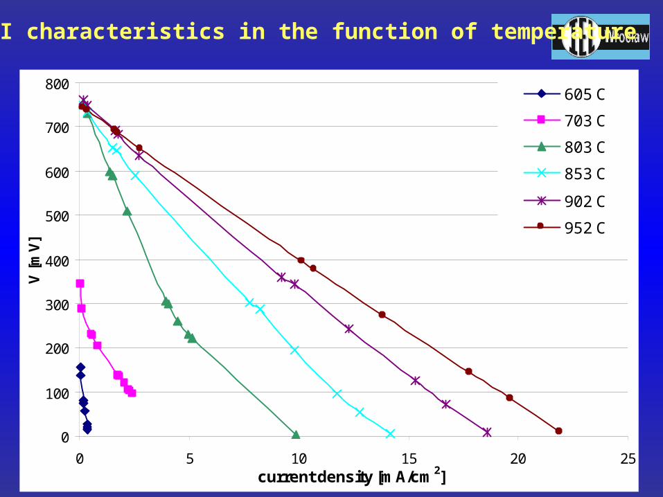
0 5 10 15 20 25current density [mA/cm2]
V [
mV
]
605 C
703 C
803 C
853 C
902 C
952 C
SOFC V-I characteristics in the function of temperature
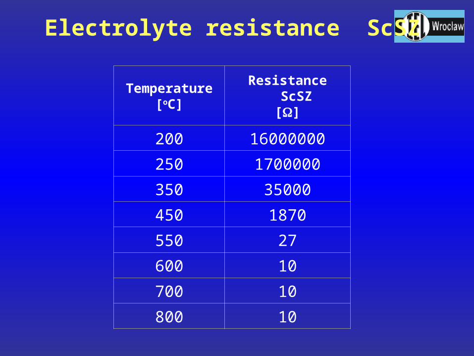
Temperature[oC]
Resistance ScSZ[]
200 16000000
250 1700000
350 35000
450 1870
550 27
600 10
700 10
800 10
Electrolyte resistance ScSZ

Designe of fuel cell test stand

Our fuel cell test stand
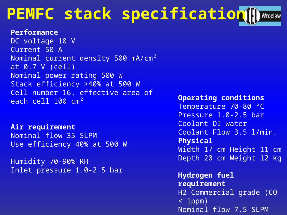
PerformanceDC voltage 10 VCurrent 50 ANominal current density 500 mA/cm² at 0.7 V (cell)Nominal power rating 500 WStack efficiency >40% at 500 WCell number 16, effective area of each cell 100 cm²
Air requirementNominal flow 35 SLPMUse efficiency 40% at 500 WHumidity 70-90% RHInlet pressure 1.0-2.5 bar
Operating conditionsTemperature 70-80 °CPressure 1.0-2.5 barCoolant DI waterCoolant Flow 3.5 l/min.PhysicalWidth 17 cm Height 11 cm Depth 20 cm Weight 12 kg
Hydrogen fuel requirementH2 Commercial grade (CO < 1ppm)Nominal flow 7.5 SLPMHumidity 70-95% RHInlet pressure 1.0-2.5 bar
PEMFC stack specification
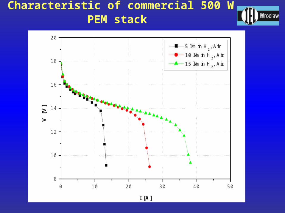
Characteristic of commercial 500 W PEM stack

Thank you for Thank you for your attention !your attention !


