83
Solar PowerOptimized Cart (SPOC) Senior Design Project Documentation Due: December 2, 2013 Group #28 Members: Jacob Bitterman Cameron Boozarjomehri William Ellett
Solar PowerOptimized Cart (SPOC)
Senior Design Project Documentation
Due: December 2, 2013
Group #28 Members:
Jacob Bitterman
Cameron Boozarjomehri
William Ellett
Table of contents 1. Executive Summary
2. Project Description
2.1. Motivation 2.2. Goals 2.3. Objectives 2.4. Project Requirements and Specifications 2.5. Limitations
3. Research related to Project Definition
3.1. Existing Similar Projects and Products 3.2. Relevant Technologies 3.3. Strategic Components
3.3.1. Cart 3.3.2. Microcontroller 3.3.3. User Interface 3.3.4. Battery 3.3.5. Solar Array
3.4. Possible Architectures and Related Diagrams 3.4.1. Solar Array Architecture 3.4.2. Motor, Battery, Micro Controller Integration 3.4.3. Electrical Integration of Battery, Cart, Panels, and UI 3.4.4. User Interface Layout
4. Project Hardware and Software Design Details
4.1. Initial Design Architecture and Related Diagrams 4.2. Solar Array Subsystem 4.3. Cart Subsystem 4.4. Power Subsystem 4.5. User Interface Subsystem
5. Design Summary of Hardware and Software
5.1. Solar Cell Charge System 5.2. Battery Motor Integration 5.3. Sensor Integration 5.4. User Interface
5.4.1. Hardware components 5.4.2. Software I/O
5.5. Vehicle Mode Modeling 6. Project Prototype Construction and Coding
6.1. Part Acquisition and Bill of Materials 6.2. PCB Vendor and Assembly 6.3. Final Coding Plan
6.3.1. Eco System 6.3.2. Performance System 6.3.3. User Interface 6.3.4. Vehicle Monitoring Integration
7. Project Prototype Testing
7.1. Hardware Test Environment 7.2. Hardware Specific Testing 7.3. Software Test Environment 7.4. Software Specific Testing
8. Administrative Content
8.1. Milestone Discussion 8.2. Budget and Finance Discussion
8.2.1. Outside Funding 8.2.2. Personal Contributions 8.2.3. Personal thanks to Duke
Appendices
Appendix A Bibliography
1 of 76
1. Executive Summary
This project sprang out of a desire to create an electrically powered cheap, efficient, and clean method of transportation for use over short to moderate distances. Many products currently exist that achieve the goal of electric transportation, but comparatively few of these use solar energy to help generate this electric fuel. Solar energy can be entirely sustainable, which has several advantages to the user and the environment. Solar power offers a cheaper alternative for the user, while also reducing the reliance on coal-based power plants. In addition, the overall cleanliness of the transportation is dependent on the electric generation methods in place within the community. The primary objective of this project is the creation of a solar-assisted electric cart capable of recharging its own batteries via the sun’s rays. This objective includes several sub-objectives that depend partially on efficient use of funds. The clearest method of evaluating the completion of the primary objective is by the range of the vehicle, the distance that it can travel without requiring additional conventional recharges via electric outlet. This range will be affected by a number of other attributes, such as solar cell efficiency, electrical system design, multi-mode operation, as well as the quality of the parts in use by the vehicle. While maintaining a financially feasible design for our team’s funding, the design will optimize all of these factors within the cart. Designing and building a vehicle like this could have a powerful impact on the way consumers in America get from place to place, particularly in large cities or other close-packed communities. The large majority of commuters are wasting gas and clogging roads with excessively large vehicles to transport a single person to and from their various destinations. A cart sized platform would minimize energy waste while maximizing space in our cities. Such densely populated locations would benefit tremendously from a practical and efficient cart design. The solar cells would allow for charging without the cost of additional infrastructure, and the small size of the vehicle would aid in increasing the efficient use of our limited transportation networks. With such a complicated design, it is necessary to set specific milestones to ensure continuous progress. Each stage on the project timeline will be discussed in greater detail in Section 8. These stages will individually come together to help achieve the most important goals of the design. The primary goals that this project hopes to achieve are as follows: environmental sustainability, market feasibility for a maximum number of viable consumers, power optimization for increased range, and financial minimization to stay within our desired budget. For each timeline stage that is reached, the project will be one step closer to maximum achievement of the previously listed goals.
2. Project Description
2 of 76
2.1 Motivation
We look to the future and hold ourselves responsible to the generation that we will leave behind. As innovators, we desire to progress and advance the human condition; America’s history of practical innovation still runs deep within our academic culture. For centuries, mankind has sought ways to find comfort, security, and convenience. In the recent past, our gaze has turned to the environment that we live in; our carelessness has brought pollution and a rapid depletion of resources to the earth. Our motivation comes from a desire to leave this world better than we found it. Our team has desired to confront a series of problems common to cities across the globe. For centuries, cities have struggled with pollution, and they still do. Since the invention of the internal combustion engine, global urban air environments have grown thick, dirty, and unhealthy. In the past 50 years, we have started to do something about it, but there is still so much work to do. Gasoline-based engines still exist as our primary source of transportation. The development of electric cars has come along way, and that is likely the way of our future. Right now though, electric cars still rely on the power of fossil fuels; improvements and innovation are continually necessary to reach a better, cleaner, and more sustainable status quo. Transportation in America has become terribly inefficient, specifically within densely populated regions. Americans live with privilege and prosperity, but this has created unnecessary issues in our transportation systems. We transport 100 people within a city in a little less than 100 cars, trucks, or vans. The design of our streets and the dense population of the city does not allow for this ratio of people to cars. There are two obvious solutions: maximize the number of people of per vehicle or minimize the “footprint” of the personal transportation. The advantage of this second solution relates to the individual autonomy of private transport that Americans strongly cling to. Our team has decided to approach the issue of inefficient inner-city transport from this “small vehicle” approach. Lastly, the rising cost of fuel has placed financial pressure on individuals to turn-away from the “traditional” gasoline-fed car. This financial pressure is a game-changing motivation for our country and our world to seek new solutions. our team seeks to address these issues and provide a feasible alternative for the cities of the world. Our whole approach to the following design is to create a personal transport that will drastically reduce pollution, alleviate common inner-city gridlock, and pull us away from our dependence on foreign non-renewable resources. We desire to leave this world better than we found it for future generations to enjoy.
2.2 Goals
To the above stated issues and problems, our design reaches out to provide solutions that are feasible and affordable to many. We seek to harness the energy of alternative and renewable resources while responsibly optimizing the use of that power for specific applications. An environmentally conscious and user compatible Solar Power Optimized
3 of 76
Cart (SPOC) offers positive answers to questions that need answering in our commuter-focused transportation world. Even with its current limitations, solar energy is a very strong answer to several problems facing America at the moment. Solar energy is accessible to all and functional in so many applications. Solar-powered components are incomparably cleaner than their gasoline-powered counterparts, reducing the dangerous effects of exhaust, carbon monoxide, and hydrocarbon-based pollution. Solar power is cheap and obviously renewable, whereas gasoline has become cripplingly expensive and hard to acquire with domestic regulation and foreign conflict in the Middle East. Although solar tech has struggles to provide adequate power for larger transportation vehicles, there are many smaller scale applications, which naturally fits with a cart-sized platform. Using a cart-sized platform provides transportation at a fraction of the footprint of modern sedans. Cutting the size of the vehicle will maximize traffic flow and power usage from the cart’s batteries and solar cell arrays. Retaining the autonomy of a personal transport while maximizing the efficient use of space on the roadways. With inner-city transport, most of the distances covered are less than 5 miles. A solar-powered cart can provide the necessary transportation with minimized traffic. Our design seeks to provide a simple and maintenance-minimized vehicle for the busy commuter. Whereas current electric vehicles need frequent recharging, our designed SPOC could be sustained with solar energy for most short distance inner-city commuting. Most electric cars are too expensive for the average consumer; our condensed and simplistic model SPOC would be inexpensive to purchase and to maintain for most potential users. Our designs seek to meet several goals: sustainability, market feasibility, power optimization, and finance minimization. The SPOC of the future will drive quietly and require minimal cost or maintenance. It will be pollution free and run on clean solar energy. Efficient sizing will allow for a better flow of traffic in our cities across the globe. Simple designs allow for reasonable pricing and a larger customer base. An environmentally conscious and user compatible Solar Power Optimized Cart (SPOC) offers positive answers to questions that need answering in our commuter-focused transportation world.
2.3 Objectives
We have a wide range of objectives, so that we can most effectively meet the needs of the user. If we can maximize the advantages and minimize the disadvantages of our cart design, our design will have the greatest likelihood of successfully entering the marketplace and benefiting our environment. We are specifically seeking a solar power optimized cart design that optimizes energy efficiency, vehicle range, velocity, capacity, size, charge time, intuitive user interfacing, GPS capability, financial cost, dependability, & safety. Our design focuses on the power interface to efficiently optimize the energy of the photovoltaic cells and the stored power in the cart batteries. We are designing the battery
4 of 76
bank to be charging whenever there is solar power to be harnessed. from the array. We desire to maximize the energy delivered to the wheels from the energy drawn from the solar array. We will look to acquire the best photovoltaic cell panels within our financial budget to maximize this efficiency. Specifically, the range optimization of the SPOC is the characteristic of our project that is easiest to judge it by. We are looking for a substantial increase in the range of the electric cart in our design. We would seek to maximize the time that the cart is usable on one battery charge, from our electrical reconfiguration. Using the solar cells and power optimization, the electric cart should then be able to travel much further than previously designed. While the range of the cart is our main focus, its speed cannot be ignored. We are seeking to maximize the cart’s speed, while improving its efficiency. Our design will maintain safe standards of maximum velocity and acceleration. We are hoping to maintain the industry speed standard for electric carts between 15-25 miles per hour. The more weight the cart can handle the better. We looking to maximize the carrying capacity of our designed solar powered cart. Our team is seeking to set a higher standard of cart carrying capacity. Our SPOC design will likely serve as an everyday form of transportation for commuters; we will optimize our design for this use. Standard carts usually carry between 2 & 4 passengers. We are hoping to meet a similar standard. Cargo capacity will also be taken into consideration. As stated in the goals, one of the largest draws of an electric cart is its size, so we’d hope to add very little to the dimensions of the standard cart. our footprint would likely be no bigger than a standard golf cart. Also when it comes to electric transportation, compact is best, so as to minimize the draw on the batteries. A minimalist design will naturally decrease the weight and likewise increase the traveling range of the cart. Quicker charging times allow the cart to keep functioning optimally.There are two ways to decrease the necessary amount of charging time for the SPOC. The electric motor energy consumption can be optimized so as to minimize the draw of charge from the batteries. Also, the efficiency of the solar cell array will minimize the amount of conventional charging time via corded battery charger. Less time charging the cart will naturally extend the range and function of our cart for greater functionality to the user. User compatibility is necessary and must not be forgotten. The energy optimization features are designed to be customizable by the user. The cart user should be able to control the distribution of power in a simple manner to use the cart optimally for their own specific situation. The user interface must be rather simple and very intuitive; the user will have a readable screen that displays the current battery life, approximate range at current use, and energy mode access. The cart user would then be able to adjust the mode to optimize range or speed based on various factors.
5 of 76
Our design has included the use of a global positioning subunit to use with the power optimization and user interface subsystems of the SPOC. The GPS functionality of the cart will allow the user interface to accurately calculate range of the cart due to energy consumption. The user will also have the ability to track his vehicle via phone or computer, if he or she so happens to lose the cart. The cart must be able to be operated safely at all times. The speed of the SPOC will be safely limited to not exceed the stability capabilities of the cart. The power interface systems will be designed to prevent dangerous power use of the batteries. As always, the electrical components must include safeguards to prevent damaging electrical fires. After the creation of a prototype, the cart will be subject to testing to ensure its safety. With a uniquely designed electrical system, our first concern will be with electrical shorts and temperature control. We will also test the durability of the solar cell electronics to assure safe and long-lasting technology. We will be working on a tight college budget with limited outside sponsorship from Duke Energy and Omni Leasing. Our team will attempt to implement our design while minimizing the cost to us and to our possible consumers. We will buy the best possible parts and materials for our design, while staying within our budget. While this does limit the technological level of the design, it also means that our design will be far more feasible to produce in a marketplace environment to a base of consumers. In a real world scenario, a cheaper product to produce and design is usually a better product to market to your customers on a large scale.
2.4 Project Requirements and Specifications
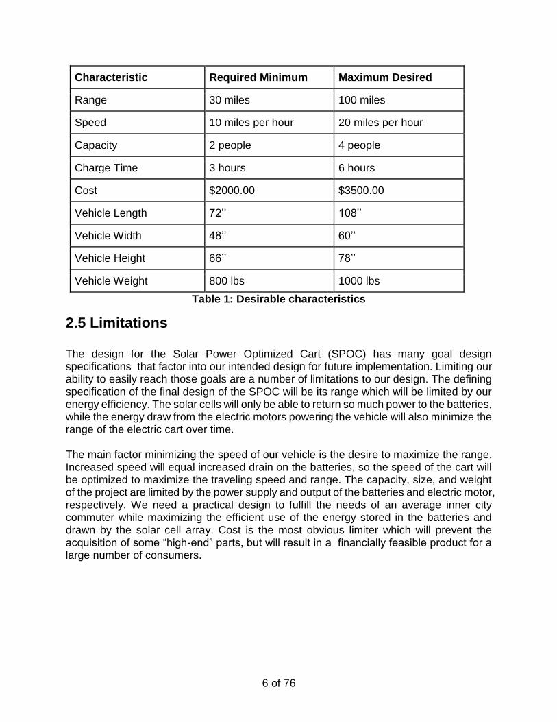
Our intended design for the Solar Power Optimized Cart is required to meet a number of specifications. These specifications will define the purpose and detailed goals of the designed cart. Range specifications are the core of the design, since the purpose of any transport is the range it can travel for its occupant. Specific speed goals are also a must, as most commuters demand a reasonable speed of travel to arrive at their destination with punctuality. Although the cart design would be small, a multi-person carrying capacity is still desirable in the marketplace. Charge time is a focus to increase the feasible use of the cart throughout the course of any day for the various needs of the user. Cost goals are to optimize the efficient use of our own funds as well as providing a quality product to a larger consumer base with a lower retail value. Vehicle dimension goals must maintain the spatial convenience and stability of the average cart platform. Optimal vehicle length will minimize the space taken on the roads and in tight inner city parking places. Vehicle width is the primary factor in the stability of the cart design, while the vehicle height is also factored into the stability and aesthetics of the design. Vehicle weight is extremely important as we attempt to maximize the range and speed of the SPOC. Excess weight will put extra strain on the electronics and battery reserves, lowering our maximum possible range and speed of the final design.
6 of 76
Characteristic Required Minimum Maximum Desired
Range 30 miles 100 miles
Speed 10 miles per hour 20 miles per hour
Capacity 2 people 4 people
Charge Time 3 hours 6 hours
Cost $2000.00 $3500.00
Vehicle Length 72’’ 108’’
Vehicle Width 48’’ 60’’
Vehicle Height 66’’ 78’’
Vehicle Weight 800 lbs 1000 lbs
Table 1: Desirable characteristics
2.5 Limitations
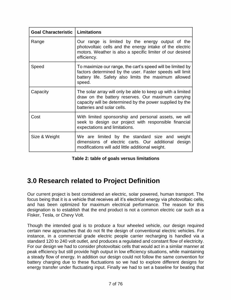
The design for the Solar Power Optimized Cart (SPOC) has many goal design specifications that factor into our intended design for future implementation. Limiting our ability to easily reach those goals are a number of limitations to our design. The defining specification of the final design of the SPOC will be its range which will be limited by our energy efficiency. The solar cells will only be able to return so much power to the batteries, while the energy draw from the electric motors powering the vehicle will also minimize the range of the electric cart over time. The main factor minimizing the speed of our vehicle is the desire to maximize the range. Increased speed will equal increased drain on the batteries, so the speed of the cart will be optimized to maximize the traveling speed and range. The capacity, size, and weight of the project are limited by the power supply and output of the batteries and electric motor, respectively. We need a practical design to fulfill the needs of an average inner city commuter while maximizing the efficient use of the energy stored in the batteries and drawn by the solar cell array. Cost is the most obvious limiter which will prevent the acquisition of some “high-end” parts, but will result in a financially feasible product for a large number of consumers.
7 of 76
Goal Characteristic Limitations
Range Our range is limited by the energy output of the photovoltaic cells and the energy intake of the electric motors. Weather is also a specific limiter of our desired efficiency.
Speed To maximize our range, the cart’s speed will be limited by factors determined by the user. Faster speeds will limit battery life. Safety also limits the maximum allowed speed.
Capacity The solar array will only be able to keep up with a limited draw on the battery reserves. Our maximum carrying capacity will be determined by the power supplied by the batteries and solar cells.
Cost With limited sponsorship and personal assets, we will seek to design our project with responsible financial expectations and limitations.
Size & Weight We are limited by the standard size and weight dimensions of electric carts. Our additional design modifications will add little additional weight.
Table 2: table of goals versus limitations
3.0 Research related to Project Definition
Our current project is best considered an electric, solar powered, human transport. The focus being that it is a vehicle that receives all it’s electrical energy via photovoltaic cells, and has been optimized for maximum electrical performance. The reason for this designation is to establish that the end product is not a common electric car such as a Fisker, Tesla, or Chevy Volt. Though the intended goal is to produce a four wheeled vehicle, our design required certain new approaches that do not fit the design of conventional electric vehicles. For instance, in a commercial grade electric people carrier recharging is handled via a standard 120 to 240 volt outlet, and produces a regulated and constant flow of electricity. For our design we had to consider photovoltaic cells that would act in a similar manner at peak efficiency but still provide high output in low efficiency situations, while maintaining a steady flow of energy. In addition our design could not follow the same convention for battery charging due to these fluctuations so we had to explore different designs for energy transfer under fluctuating input. Finally we had to set a baseline for beating that
8 of 76
existed within current technologies. for this we chose UCF’s own purely solar vehicle which we explored in depth as you will see.
3.1 Existing Similar Projects and Products
This section focuses on projects and products that are currently on the market. The majority of these are vehicles that follow our model of a strictly solar powered electric vehicle meant to be driven in suburban/urban areas. We will also look at existing technologies pertaining to our components such as Photovoltaic cells, Improved battery and battery control technology. Most importantly the goal of this section is to analyse existing system to see if we can improve upon them, or better integrate them into our own design. An important note to make is that some of these products are experimental and others are commercialized so the cost factor for either may not be accurate.
3.1.1 SEV (Solar Electric Vehicles)
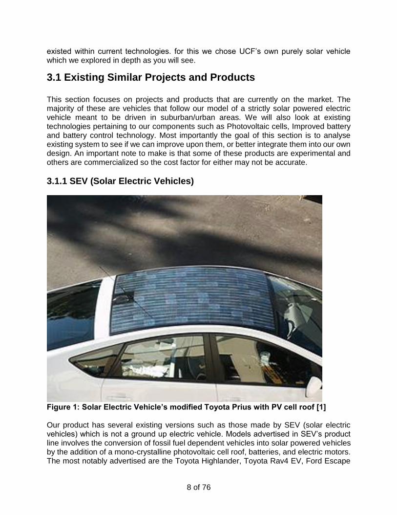
Figure 1: Solar Electric Vehicle’s modified Toyota Prius with PV cell roof [1] Our product has several existing versions such as those made by SEV (solar electric vehicles) which is not a ground up electric vehicle. Models advertised in SEV’s product line involves the conversion of fossil fuel dependent vehicles into solar powered vehicles by the addition of a mono-crystalline photovoltaic cell roof, batteries, and electric motors. The most notably advertised are the Toyota Highlander, Toyota Rav4 EV, Ford Escape
9 of 76
Hybrid, Dodge Sprinter Hybrid, and the most notable Toyota Prius. These products also includes solid state device electronics for monitoring battery charging and dissipation over the course of the vehicles operational lifetime. The intent is to boost fuel economy by 34-60% pending user driving habits by improving fuel efficiency of the vehicle and giving it a more intelligent control over how the vehicle distributes it’s energy. This is relevant to our product in that we also intend to have intelligent vehicle energy dissipation that can improve vehicle driving via selection of different drive modes. In addition our design will involve the fabrication of a vehicle that is electric from the ground up. This is in contrast to SEV’s line of “electric” vehicles that are essentially hybrid vehicles intended to boost performance in regard to the vehicles original fossil fuel design. The current price for a SEV converted recycled Toyota Prius is $25,000. This is one of their cheaper products and it is our goal to produce a machine that is as efficient as the prius but at a significantly cheaper cost. However it should be noted that our product will have a lower top speed. but in regard to its intended purpose and the cost benefits, this difference in speed will be mostly negligible.
3.1.2 Tindo Solar Bus
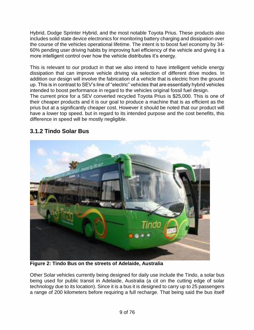
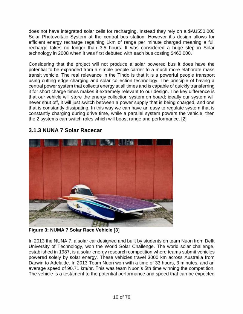
Figure 2: Tindo Bus on the streets of Adelaide, Australia Other Solar vehicles currently being designed for daily use include the Tindo, a solar bus being used for public transit in Adelaide, Australia (a cit on the cutting edge of solar technology due to its location). Since it is a bus it is designed to carry up to 25 passengers a range of 200 kilometers before requiring a full recharge. That being said the bus itself
10 of 76
does not have integrated solar cells for recharging. Instead they rely on a $AU550,000 Solar Photovoltaic System at the central bus station. However it’s design allows for efficient energy recharge regaining 1km of range per minute charged meaning a full recharge takes no longer than 3.5 hours. It was considered a huge step in Solar technology in 2008 when it was first debuted with each bus costing $460,000. Considering that the project will not produce a solar powered bus it does have the potential to be expanded from a simple people carrier to a much more elaborate mass transit vehicle. The real relevance in the Tindo is that it is a powerful people transport using cutting edge charging and solar collection technology. The principle of having a central power system that collects energy at all times and is capable of quickly transferring it for short charge times makes it extremely relevant to our design. The key difference is that our vehicle will store the energy collection system on board; ideally our system will never shut off, it will just switch between a power supply that is being charged, and one that is constantly dissipating. In this way we can have an easy to regulate system that is constantly charging during drive time, while a parallel system powers the vehicle; then the 2 systems can switch roles which will boost range and performance. [2]
3.1.3 NUNA 7 Solar Racecar
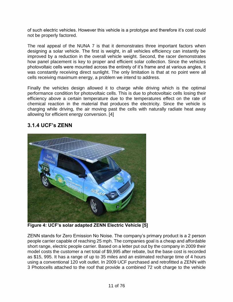
Figure 3: NUMA 7 Solar Race Vehicle [3] In 2013 the NUNA 7, a solar car designed and built by students on team Nuon from Delft University of Technology, won the World Solar Challenge. The world solar challenge, established in 1987, is a solar energy research competition where teams submit vehicles powered solely by solar energy. These vehicles travel 3000 km across Australia from Darwin to Adelaide. In 2013 Team Nuon won with a time of 33 hours, 3 minutes, and an average speed of 90.71 km/hr. This was team Nuon’s 5th time winning the competition. The vehicle is a testament to the potential performance and speed that can be expected
11 of 76
of such electric vehicles. However this vehicle is a prototype and therefore it’s cost could not be properly factored. The real appeal of the NUNA 7 is that it demonstrates three important factors when designing a solar vehicle. The first is weight, in all vehicles efficiency can instantly be improved by a reduction in the overall vehicle weight. Second, the racer demonstrates how panel placement is key to proper and efficient solar collection. Since the vehicles photovoltaic cells were mounted across the entirety of it’s frame and at various angles, it was constantly receiving direct sunlight. The only limitation is that at no point were all cells receiving maximum energy, a problem we intend to address. Finally the vehicles design allowed it to charge while driving which is the optimal performance condition for photovoltaic cells. This is due to photovoltaic cells losing their efficiency above a certain temperature due to the temperatures effect on the rate of chemical reaction in the material that produces the electricity. Since the vehicle is charging while driving, the air moving past the cells with naturally radiate heat away allowing for efficient energy conversion. [4]
3.1.4 UCF’s ZENN
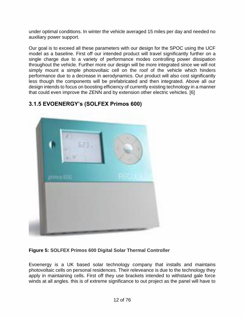
Figure 4: UCF’s solar adapted ZENN Electric Vehicle [5] ZENN stands for Zero Emission No Noise. The company’s primary product is a 2 person people carrier capable of reaching 25 mph. The companies goal is a cheap and affordable short range, electric people carrier. Based on a letter put out by the company in 2009 their model costs the customer a net total of $9,995 after rebate, but the base cost is recorded as $15, 995. It has a range of up to 35 miles and an estimated recharge time of 4 hours using a conventional 120 volt outlet. In 2009 UCF purchased and retrofitted a ZENN with 3 Photocells attached to the roof that provide a combined 72 volt charge to the vehicle
12 of 76
under optimal conditions. In winter the vehicle averaged 15 miles per day and needed no auxiliary power support.
Our goal is to exceed all these parameters with our design for the SPOC using the UCF model as a baseline. First off our intended product will travel significantly further on a single charge due to a variety of performance modes controlling power dissipation throughout the vehicle. Further more our design will be more integrated since we will not simply mount a simple photovoltaic cell on the roof of the vehicle which hinders performance due to a decrease in aerodynamics. Our product will also cost significantly less though the components will be prefabricated and then integrated. Above all our design intends to focus on boosting efficiency of currently existing technology in a manner that could even improve the ZENN and by extension other electric vehicles. [6]
3.1.5 EVOENERGY’s (SOLFEX Primos 600)
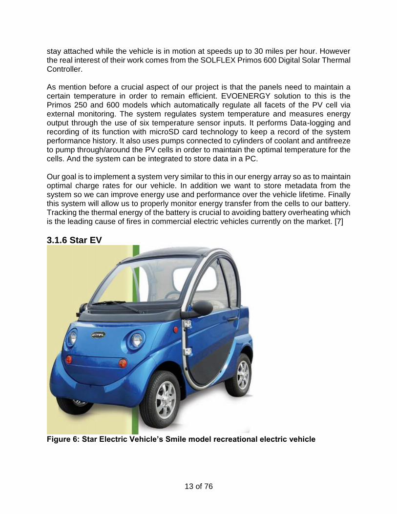
Figure 5: SOLFEX Primos 600 Digital Solar Thermal Controller
Evoenergy is a UK based solar technology company that installs and maintains photovoltaic cells on personal residences. Their releveance is due to the technology they apply in maintaining cells. First off they use brackets intended to withstand gale force winds at all angles. this is of extreme significance to out project as the panel will have to
13 of 76
stay attached while the vehicle is in motion at speeds up to 30 miles per hour. However the real interest of their work comes from the SOLFLEX Primos 600 Digital Solar Thermal Controller. As mention before a crucial aspect of our project is that the panels need to maintain a certain temperature in order to remain efficient. EVOENERGY solution to this is the Primos 250 and 600 models which automatically regulate all facets of the PV cell via external monitoring. The system regulates system temperature and measures energy output through the use of six temperature sensor inputs. It performs Data-logging and recording of its function with microSD card technology to keep a record of the system performance history. It also uses pumps connected to cylinders of coolant and antifreeze to pump through/around the PV cells in order to maintain the optimal temperature for the cells. And the system can be integrated to store data in a PC. Our goal is to implement a system very similar to this in our energy array so as to maintain optimal charge rates for our vehicle. In addition we want to store metadata from the system so we can improve energy use and performance over the vehicle lifetime. Finally this system will allow us to properly monitor energy transfer from the cells to our battery. Tracking the thermal energy of the battery is crucial to avoiding battery overheating which is the leading cause of fires in commercial electric vehicles currently on the market. [7]
3.1.6 Star EV
Figure 6: Star Electric Vehicle’s Smile model recreational electric vehicle
14 of 76
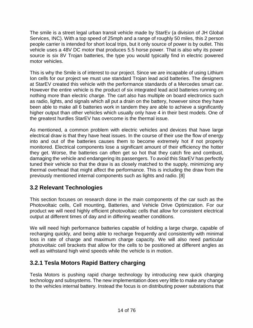
The smile is a street legal urban transit vehicle made by StarEv (a division of JH Global Services, INC). With a top speed of 25mph and a range of roughly 50 miles, this 2 person people carrier is intended for short local trips, but it only source of power is by outlet. This vehicle uses a 48V DC motor that produces 5.5 horse power. That is also why its power source is six 8V Trojan batteries, the type you would typically find in electric powered motor vehicles. This is why the Smile is of interest to our project. Since we are incapable of using Lithium Ion cells for our project we must use standard Trojan lead acid batteries. The designers at StarEV created this vehicle with the performance standards of a Mercedes smart car. However the entire vehicle is the product of six integrated lead acid batteries running on nothing more than electric charge. The cart also has multiple on board electronics such as radio, lights, and signals which all put a drain on the battery, however since they have been able to make all 6 batteries work in tandem they are able to achieve a significantly higher output than other vehicles which usually only have 4 in their best models. One of the greatest hurdles StarEV has overcome is the thermal issue. As mentioned, a common problem with electric vehicles and devices that have large electrical draw is that they have heat issues. In the course of their use the flow of energy into and out of the batteries causes them to become extremely hot if not properly monitored. Electrical components lose a significant amount of their efficiency the hotter they get. Worse, the batteries can often get so hot that they catch fire and combust, damaging the vehicle and endangering its passengers. To avoid this StarEV has perfectly tuned their vehicle so that the draw is as closely matched to the supply, minimizing any thermal overhead that might affect the performance. This is including the draw from the previously mentioned internal components such as lights and radio. [8]
3.2 Relevant Technologies
This section focuses on research done in the main components of the car such as the Photovoltaic cells, Cell mounting, Batteries, and Vehicle Drive Optimization. For our product we will need highly efficient photovoltaic cells that allow for consistent electrical output at different times of day and in differing weather conditions. We will need high performance batteries capable of holding a large charge, capable of recharging quickly, and being able to recharge frequently and consistently with minimal loss in rate of charge and maximum charge capacity. We will also need particular photovoltaic cell brackets that allow for the cells to be positioned at different angles as well as withstand high wind speeds while the vehicle is in motion.
3.2.1 Tesla Motors Rapid Battery charging
Tesla Motors is pushing rapid charge technology by introducing new quick charging technology and subsystems. The new implementation does very little to make any change to the vehicles internal battery. Instead the focus is on distributing power substations that
15 of 76
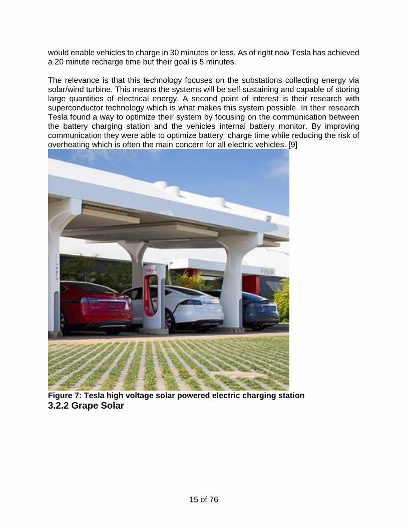
would enable vehicles to charge in 30 minutes or less. As of right now Tesla has achieved a 20 minute recharge time but their goal is 5 minutes. The relevance is that this technology focuses on the substations collecting energy via solar/wind turbine. This means the systems will be self sustaining and capable of storing large quantities of electrical energy. A second point of interest is their research with superconductor technology which is what makes this system possible. In their research Tesla found a way to optimize their system by focusing on the communication between the battery charging station and the vehicles internal battery monitor. By improving communication they were able to optimize battery charge time while reducing the risk of overheating which is often the main concern for all electric vehicles. [9]
Figure 7: Tesla high voltage solar powered electric charging station
3.2.2 Grape Solar
16 of 76
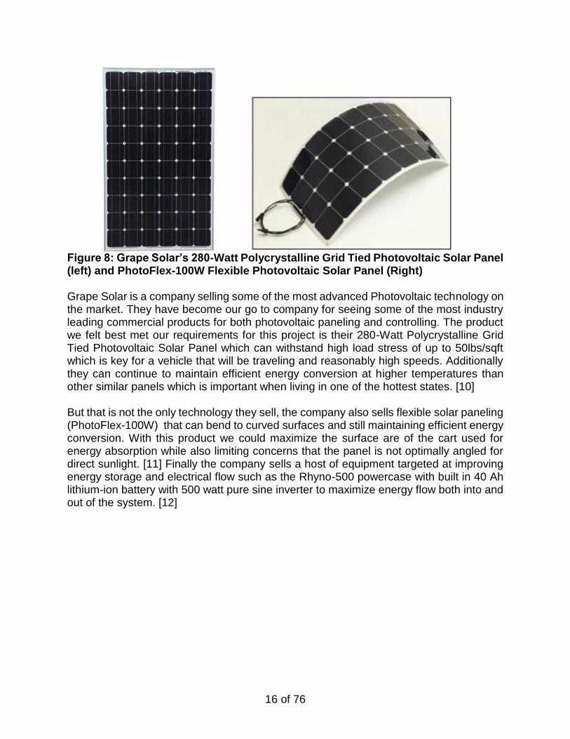
Figure 8: Grape Solar’s 280-Watt Polycrystalline Grid Tied Photovoltaic Solar Panel (left) and PhotoFlex-100W Flexible Photovoltaic Solar Panel (Right) Grape Solar is a company selling some of the most advanced Photovoltaic technology on the market. They have become our go to company for seeing some of the most industry leading commercial products for both photovoltaic paneling and controlling. The product we felt best met our requirements for this project is their 280-Watt Polycrystalline Grid Tied Photovoltaic Solar Panel which can withstand high load stress of up to 50lbs/sqft which is key for a vehicle that will be traveling and reasonably high speeds. Additionally they can continue to maintain efficient energy conversion at higher temperatures than other similar panels which is important when living in one of the hottest states. [10] But that is not the only technology they sell, the company also sells flexible solar paneling (PhotoFlex-100W) that can bend to curved surfaces and still maintaining efficient energy conversion. With this product we could maximize the surface are of the cart used for energy absorption while also limiting concerns that the panel is not optimally angled for direct sunlight. [11] Finally the company sells a host of equipment targeted at improving energy storage and electrical flow such as the Rhyno-500 powercase with built in 40 Ah lithium-ion battery with 500 watt pure sine inverter to maximize energy flow both into and out of the system. [12]
17 of 76
3.2.3 Electric Energy and Power Consumption by Light-Duty Plug-In Electric Vehicles
This is research done by the Iowa State University Electrical & Computer Engineering Department. In this work they did mathematical models to determine typical energy dispersal patterns of cars in different urban environments. These models focused on typical user commutes to locations such as work, school, grocery store, etc. The research was particularly significant because the models produced allowed for accurate tracking of power dissipation in electric vehicles in conditions that are usually stop and go due to low speed limits, frequent turns, and short trip times. The models are particularly useful to our project since our vehicle is intended for lower speeds, typically less than that of highways. The research also showed models intended to optimize power consumption over both a 24 hour and 7 day period in a manner that was self adjusting. The combination of these elements means we can design the on board computer to improve vehicle efficiency as the vehicle is used more frequently. While collecting data about vehicle drive habits the computer could also calculate and compensate for the decay of internal systems such as the battery so that users can be notified when they need to replace components or adjust driving habits. [13]
3.2.4 Battery Requirements for Plug-In Hybrid Electric Vehicles – Analysis and Rationale
Research done by Professor Ahmad Pesaran, Ph.D has given insight into the battery demands of electric vehicles. His work gave current and future projections of battery demands of these vehicles based on the systems they incorporate, projections of the future of battery material’s technology, and the different purposes of the vehicles themselves. he determined there were two categories of batteries for all-electric range cars(vehicle relying solely on battery for operation), one for a 10-mile(Low E/P) range and one for a 40-mile range (high E/P) were selected. The batteries then had to be chosen of the criteria of: charge-depleting HEV mode (available energy and power) charge-sustaining HEV mode (available energy and cold cranking) system-level (cost, volume/weight, calendar and cycle life) battery limits (voltage, current and temperature) To expand these goals mean how well can the batteries dissipate charge, how well can they hold charge when not in use, how much does the battery cost in comparison to it’s purpose and longevity, and finally what were the physical limits of the material of the battery in terms of maximum charge it could dissipate or receive while maintaining safe and operable temperature. The research determined that in these low range vehicles the difficult to meet many of the requirements being demanded by this proposal for long range cost/life/energy density batteries.
18 of 76
This research also touched on different battery depletion modes. For our project we intend to use an efficient, performance, and ecoboost as our primary vehicle drive modes. All of which will be operating on a constant charge depleting mode as expected in electric vehicles. [14]
3.2.5 Designing a High-Efficiency Solar Power Battery Charger
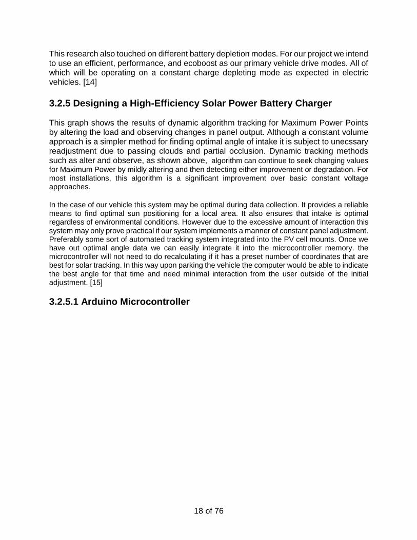
This graph shows the results of dynamic algorithm tracking for Maximum Power Points by altering the load and observing changes in panel output. Although a constant volume approach is a simpler method for finding optimal angle of intake it is subject to unecssary readjustment due to passing clouds and partial occlusion. Dynamic tracking methods such as alter and observe, as shown above, algorithm can continue to seek changing values
for Maximum Power by mildly altering and then detecting either improvement or degradation. For most installations, this algorithm is a significant improvement over basic constant voltage approaches. In the case of our vehicle this system may be optimal during data collection. It provides a reliable means to find optimal sun positioning for a local area. It also ensures that intake is optimal regardless of environmental conditions. However due to the excessive amount of interaction this system may only prove practical if our system implements a manner of constant panel adjustment. Preferably some sort of automated tracking system integrated into the PV cell mounts. Once we have out optimal angle data we can easily integrate it into the microcontroller memory. the microcontroller will not need to do recalculating if it has a preset number of coordinates that are best for solar tracking. In this way upon parking the vehicle the computer would be able to indicate the best angle for that time and need minimal interaction from the user outside of the initial adjustment. [15]
3.2.5.1 Arduino Microcontroller
19 of 76
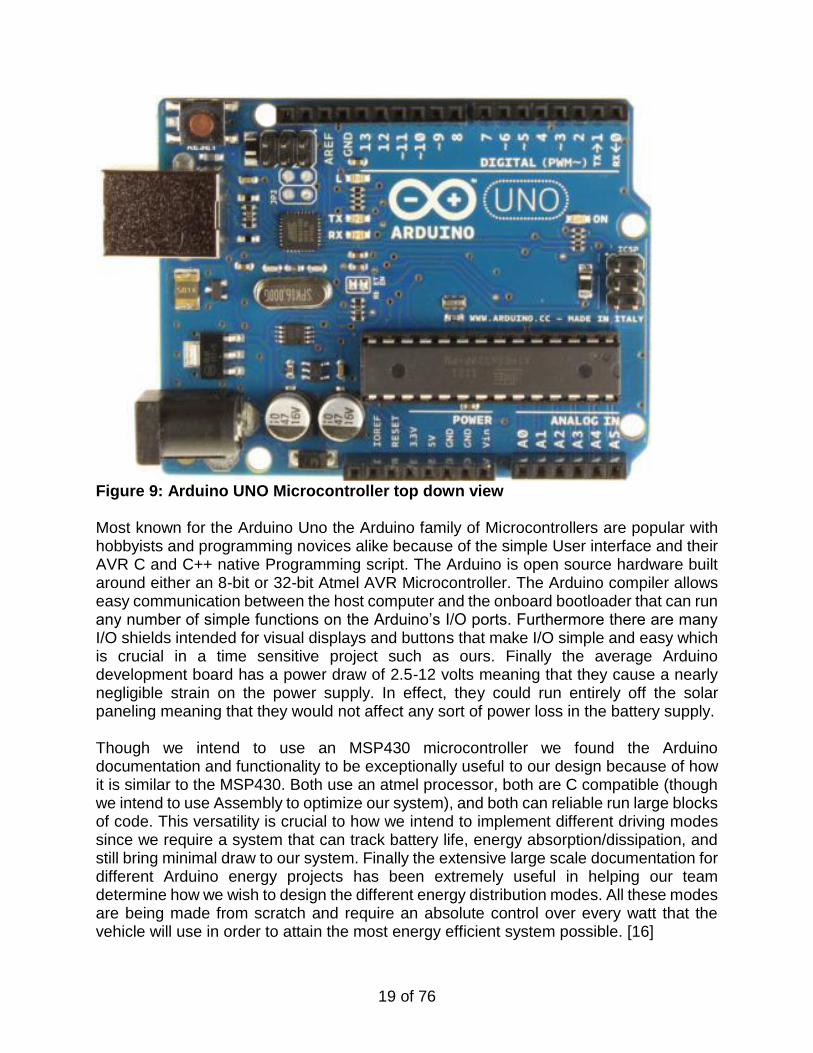
Figure 9: Arduino UNO Microcontroller top down view Most known for the Arduino Uno the Arduino family of Microcontrollers are popular with hobbyists and programming novices alike because of the simple User interface and their AVR C and C++ native Programming script. The Arduino is open source hardware built around either an 8-bit or 32-bit Atmel AVR Microcontroller. The Arduino compiler allows easy communication between the host computer and the onboard bootloader that can run any number of simple functions on the Arduino’s I/O ports. Furthermore there are many I/O shields intended for visual displays and buttons that make I/O simple and easy which is crucial in a time sensitive project such as ours. Finally the average Arduino development board has a power draw of 2.5-12 volts meaning that they cause a nearly negligible strain on the power supply. In effect, they could run entirely off the solar paneling meaning that they would not affect any sort of power loss in the battery supply. Though we intend to use an MSP430 microcontroller we found the Arduino documentation and functionality to be exceptionally useful to our design because of how it is similar to the MSP430. Both use an atmel processor, both are C compatible (though we intend to use Assembly to optimize our system), and both can reliable run large blocks of code. This versatility is crucial to how we intend to implement different driving modes since we require a system that can track battery life, energy absorption/dissipation, and still bring minimal draw to our system. Finally the extensive large scale documentation for different Arduino energy projects has been extremely useful in helping our team determine how we wish to design the different energy distribution modes. All these modes are being made from scratch and require an absolute control over every watt that the vehicle will use in order to attain the most energy efficient system possible. [16]
20 of 76
3.2.5.2 Arduino Bluetooth Vehicle integration Components
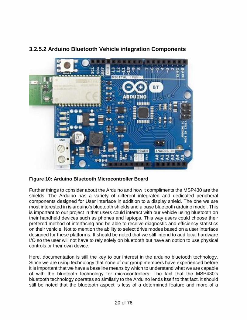
Figure 10: Arduino Bluetooth Microcontroller Board Further things to consider about the Arduino and how it compliments the MSP430 are the shields. The Arduino has a variety of different integrated and dedicated peripheral components designed for User interface in addition to a display shield. The one we are most interested in is arduino’s bluetooth shields and a base bluetooth arduino model. This is important to our project in that users could interact with our vehicle using bluetooth on their handheld devices such as phones and laptops. This way users could choose their prefered method of interfacing and be able to receive diagnostic and efficiency statistics on their vehicle. Not to mention the ability to select drive modes based on a user interface designed for these platforms. It should be noted that we still intend to add local hardware I/O so the user will not have to rely solely on bluetooth but have an option to use physical controls or their own device. Here, documentation is still the key to our interest in the arduino bluetooth technology. Since we are using technology that none of our group members have experienced before it is important that we have a baseline means by which to understand what we are capable of with the bluetooth technology for microcontrollers. The fact that the MSP430’s bluetooth technology operates so similarly to the Arduino lends itself to that fact. it should still be noted that the bluetooth aspect is less of a determined feature and more of a
21 of 76
desirable. However it is this advanced user integration that we feel will let our project stand apart from prior solar vehicle technology, and represent a new generation of modern energy conservation projects. [17]
3.2.5.3 MSP430 CC2560 Bluetooth® / Dual-Mode Evaluation Module
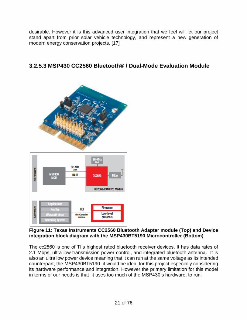
Figure 11: Texas Instruments CC2560 Bluetooth Adapter module (Top) and Device integration block diagram with the MSP430BT5190 Microcontroller (Bottom) The cc2560 is one of TI’s highest rated bluetooth receiver devices. It has data rates of 2.1 Mbps, ultra low transmission power control, and integrated bluetooth antenna. It is also an ultra low power device meaning that it can run at the same voltage as its intended counterpart, the MSP430BT5190. it would be ideal for this project especially considering its hardware performance and integration. However the primary limitation for this model in terms of our needs is that it uses too much of the MSP430’s hardware, to run.
22 of 76
As you can see above the cc2560 holds its antenna, internal clock, and firmware protocols which means that it is optimized on a hardware level for its intended purpose of sending and receiving as a bluetooth device. However as a piece of hardware it is surprisingly heavy despite having all low-level protocols stored with the firmware. This is due to how much of its counterparts MCU it uses in terms of need to storing the bluetooth stack, applications, and operating system. For our project the MSP430 must communicate with the receiver while tracking the behavior of internal components. It cannot have such a significant amount of its processing power weighed down by a local peripheral. especially when considering how little the bluetooth receiver will actually have to react with the MSP430. Other Bluetooth transmitters such as the RN-42, our intended bluetooth receiver, stores all necessary data and performs that majority of functions locally on itself. The tradeoff is that since it has so many components it has a higher power draw. That being said in a system as large as ours this draw is nearly negligible. It should be noted though that it maybe better to consider the cc2560 and the MSP430BT5190 as a whole communicating with the onboard MSP430 so that the computational draw is at a complete minimum in addition to the lowered power costs. [18]
3.3 Strategic Components
Strategic components refers to the design integral components. This section is primarily focusing on what components were being considered as actually usable given the nature and needs of the project. The focal point of the project were a stable cart. Ideally a cart capable of supporting the passengers, and added weight from the batteries and solar panels. Other primary components were the batteries themselves. Necessarily ones that can hold a powerful charge, dissipate efficiently, and be recharged a great many times. Photovoltaic solar panels were also a key concern since we needed technologies that would allow for charging. Additionally, since this is Florida, we needed paneling that would be able to operate effectively at hot temperatures. The limitation is that the majority of this technology loses its efficiency the hotter it gets. And the final key components for consideration was the microcontroller. For this our focus was something easy to program. It needed to have low power draw and ideally be capable of standby modes considering that solar technology is only efficient during the day. Finally it would need to be handle many different I/O’s. In this case the inputs would include voltage, thermal sensing, and finally, photodetectors. Outputs would include LCD displays and possible bluetooth antennas
3.3.1 Cart
23 of 76
We need a proper platform for our unique electrical platform to function properly which means choosing an existing car design that is stable, compact, and electrically sound. There are several options to choose from for our electric cart platform. Our main concerns for this component are the range and financial cost of the several options available to us. With these considerations, our decision will be based on the feasibility of our own acquisition of some electric cart design
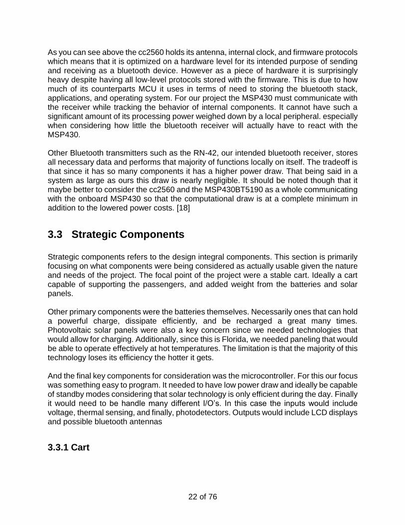
3.3.1.1 “Star EV Smile” Design Star EV makes high end electric vehicles for a myriad of purposes and users. Their “Smile”design uses a highly efficient electrical motor system to power the vehicle from a bank of 6 8V Trojan batteries. This design rides the rail between electric car and cart with its fully enclosed body and street legal specifications. Though it has a stylish exterior and an efficient electrical platform for our design to be built from, the financial cost of this design may prevent its use in our chosen design. [30]
Figure 12: Star EV “Smile” Model Cart
This design rides the rail between electric car and cart with its fully enclosed body and street legal specifications. Though it has a stylish exterior and an efficient electrical platform for our design to be built from, the financial cost of this design may prevent its use in our chosen design.
3.3.1.2 “Club Car” Cart Design
24 of 76
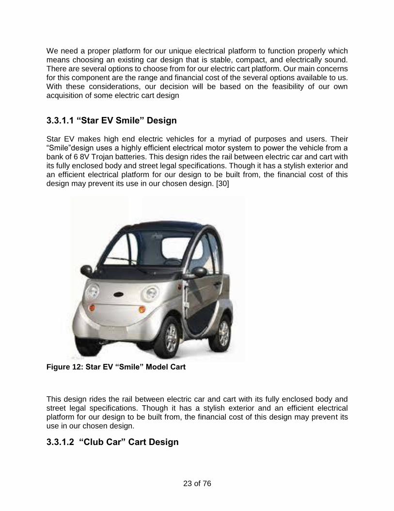
Our most financially viable option is the classic “Club Car” or “EZGO” cart design popular on golf courses worldwide. Their construction is simple and inexpensive; the cart’s is made of light materials such as plastic and fiberglass. The frame is made of aluminum to reduce weight. These vehicles usually have a varying amount of power of 9-12 horsepower, running off of an array of lead-acid batteries underneath the seats. The main draw of this design is the affordability for our team’s budget. Classic electric carts are plentiful, widespread, and inexpensive. [31]:
Figure 13: “Club Car” brand classic golf cart platform
3.3.1.3 GEM Cart Design
25 of 76
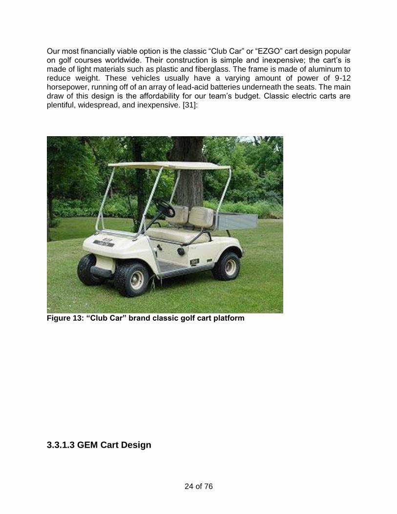
Figure 14: Polaris GEM Cart design Global Electric Motorcars(a subsidiary of Polaris) has designed a new style of cart in past years that has gained a wide base of support. The GEM cart offers added features but at a price. These cart drove at an average of 20 mph on a 72 volt battery system. Their electrical design offers greater power efficiency and battery usage. This design is obviously more aerodynamic, stylish, and safe with its featured seatbelt. Our main concern with this GEM design is the financial cost: most of these carts price at twice the cost of the classic “Club Car” design. [32]
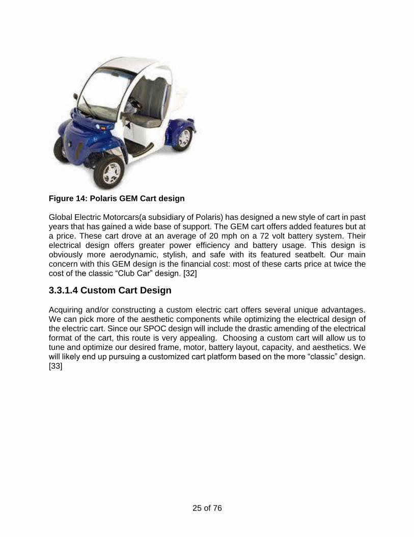
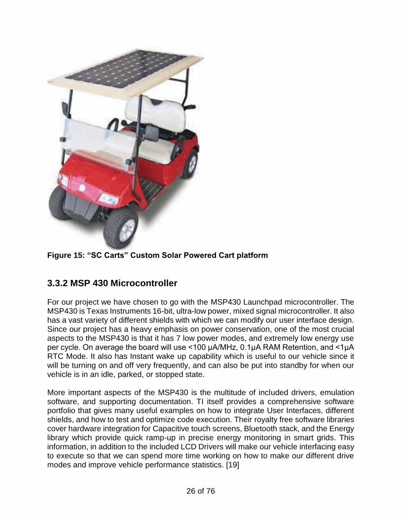
3.3.1.4 Custom Cart Design Acquiring and/or constructing a custom electric cart offers several unique advantages. We can pick more of the aesthetic components while optimizing the electrical design of the electric cart. Since our SPOC design will include the drastic amending of the electrical format of the cart, this route is very appealing. Choosing a custom cart will allow us to tune and optimize our desired frame, motor, battery layout, capacity, and aesthetics. We will likely end up pursuing a customized cart platform based on the more “classic” design. [33]
26 of 76
Figure 15: “SC Carts” Custom Solar Powered Cart platform
3.3.2 MSP 430 Microcontroller
For our project we have chosen to go with the MSP430 Launchpad microcontroller. The MSP430 is Texas Instruments 16-bit, ultra-low power, mixed signal microcontroller. It also has a vast variety of different shields with which we can modify our user interface design. Since our project has a heavy emphasis on power conservation, one of the most crucial aspects to the MSP430 is that it has 7 low power modes, and extremely low energy use per cycle. On average the board will use <100 μA/MHz, 0.1μA RAM Retention, and <1μA RTC Mode. It also has Instant wake up capability which is useful to our vehicle since it will be turning on and off very frequently, and can also be put into standby for when our vehicle is in an idle, parked, or stopped state. More important aspects of the MSP430 is the multitude of included drivers, emulation software, and supporting documentation. TI itself provides a comprehensive software portfolio that gives many useful examples on how to integrate User Interfaces, different shields, and how to test and optimize code execution. Their royalty free software libraries cover hardware integration for Capacitive touch screens, Bluetooth stack, and the Energy library which provide quick ramp-up in precise energy monitoring in smart grids. This information, in addition to the included LCD Drivers will make our vehicle interfacing easy to execute so that we can spend more time working on how to make our different drive modes and improve vehicle performance statistics. [19]
27 of 76
Figure 18: Texas Instruments MSP430 Launchpad Microcontroller
3.3.3 User Interface In order to allow for some degree of user control, we need to include both input and output options for the user. These options will include the display and hardware buttons shown below. Additional software will be designed to link these components; this software will be discussed in later sections.
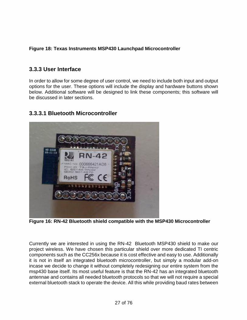
3.3.3.1 Bluetooth Microcontroller
Figure 16: RN-42 Bluetooth shield compatible with the MSP430 Microcontroller Currently we are interested in using the RN-42 Bluetooth MSP430 shield to make our project wireless. We have chosen this particular shield over more dedicated TI centric components such as the CC256x because it is cost effective and easy to use. Additionally it is not in itself an integrated bluetooth microcontroller, but simply a modular add-on incase we decide to change it without completely redesigning our entire system from the msp430 base itself. Its most useful feature is that the RN-42 has an integrated bluetooth antennae and contains all needed bluetooth protocols so that we will not require a special external bluetooth stack to operate the device. All this while providing baud rates between
28 of 76
1200 bps and 921 Kbps. This greatly cuts down on overhead on the MSP430 while still allowing us to have the full bluetooth functionality we desire. It should be noted however, that the RN-42 requires a minimum of 3V input which is takes us well above the minimal 1.8 normally needed to run the MSP430 alone. Though this tradeoff is somewhat inconvenient it is nearly negligible when compared to the overall energy draw of the vehicle. Additionally we intend to power all the onboard systems with the obvious exception of the actually drivetrain itself, using the solar energy being collected while the vehicle is in drive. Ideally we will still have such a low energy draw by the onboard diagnostic components that we will still be able to do partial charging while th e vehicle is mobile. [20]
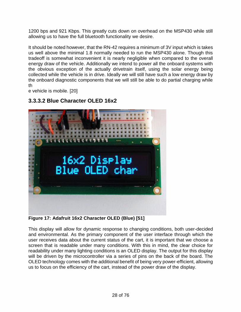
3.3.3.2 Blue Character OLED 16x2
Figure 17: Adafruit 16x2 Character OLED (Blue) [51] This display will allow for dynamic response to changing conditions, both user-decided and environmental. As the primary component of the user interface through which the user receives data about the current status of the cart, it is important that we choose a screen that is readable under many conditions. With this in mind, the clear choice for readability under many lighting conditions is an OLED display. The output for this display will be driven by the microcontroller via a series of pins on the back of the board. The OLED technology comes with the additional benefit of being very power-efficient, allowing us to focus on the efficiency of the cart, instead of the power draw of the display.
29 of 76
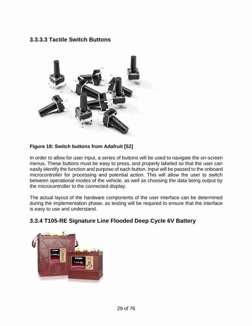
3.3.3.3 Tactile Switch Buttons
Figure 18: Switch buttons from Adafruit [52] In order to allow for user input, a series of buttons will be used to navigate the on-screen menus. These buttons must be easy to press, and properly labeled so that the user can easily identify the function and purpose of each button. Input will be passed to the onboard microcontroller for processing and potential action. This will allow the user to switch between operational modes of the vehicle, as well as choosing the data being output by the microcontroller to the connected display. The actual layout of the hardware components of the user interface can be determined during the implementation phase, as testing will be required to ensure that the interface is easy to use and understand.
3.3.4 T105-RE Signature Line Flooded Deep Cycle 6V Battery
30 of 76
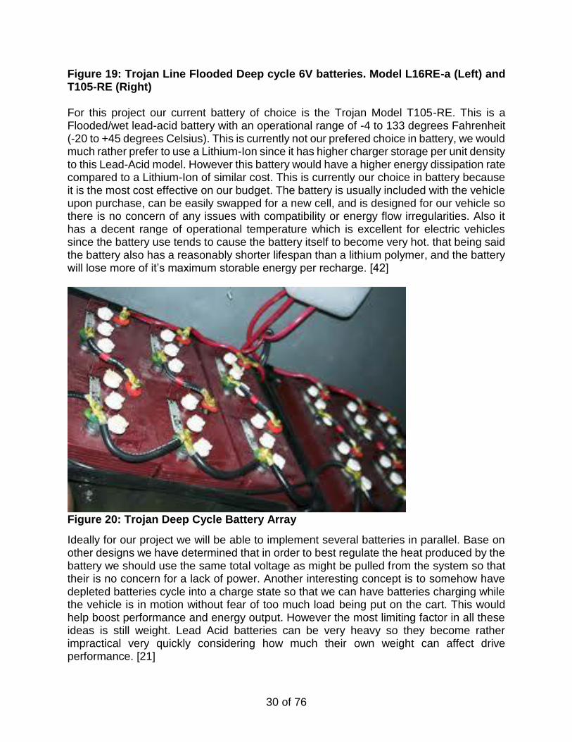
Figure 19: Trojan Line Flooded Deep cycle 6V batteries. Model L16RE-a (Left) and T105-RE (Right) For this project our current battery of choice is the Trojan Model T105-RE. This is a Flooded/wet lead-acid battery with an operational range of -4 to 133 degrees Fahrenheit (-20 to +45 degrees Celsius). This is currently not our prefered choice in battery, we would much rather prefer to use a Lithium-Ion since it has higher charger storage per unit density to this Lead-Acid model. However this battery would have a higher energy dissipation rate compared to a Lithium-Ion of similar cost. This is currently our choice in battery because it is the most cost effective on our budget. The battery is usually included with the vehicle upon purchase, can be easily swapped for a new cell, and is designed for our vehicle so there is no concern of any issues with compatibility or energy flow irregularities. Also it has a decent range of operational temperature which is excellent for electric vehicles since the battery use tends to cause the battery itself to become very hot. that being said the battery also has a reasonably shorter lifespan than a lithium polymer, and the battery will lose more of it’s maximum storable energy per recharge. [42]
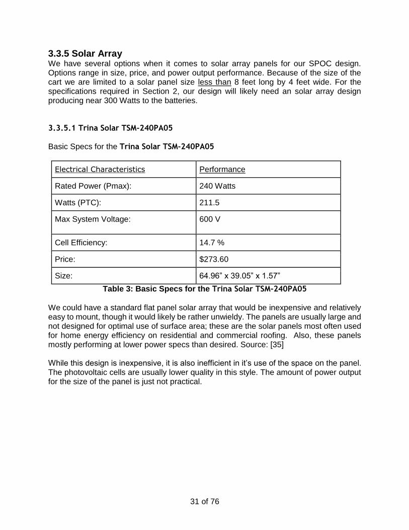
Figure 20: Trojan Deep Cycle Battery Array
Ideally for our project we will be able to implement several batteries in parallel. Base on other designs we have determined that in order to best regulate the heat produced by the battery we should use the same total voltage as might be pulled from the system so that their is no concern for a lack of power. Another interesting concept is to somehow have depleted batteries cycle into a charge state so that we can have batteries charging while the vehicle is in motion without fear of too much load being put on the cart. This would help boost performance and energy output. However the most limiting factor in all these ideas is still weight. Lead Acid batteries can be very heavy so they become rather impractical very quickly considering how much their own weight can affect drive performance. [21]
31 of 76
3.3.5 Solar Array We have several options when it comes to solar array panels for our SPOC design. Options range in size, price, and power output performance. Because of the size of the cart we are limited to a solar panel size less than 8 feet long by 4 feet wide. For the specifications required in Section 2, our design will likely need an solar array design producing near 300 Watts to the batteries. 3.3.5.1 Trina Solar TSM-240PA05
Basic Specs for the Trina Solar TSM-240PA05
Electrical Characteristics Performance
Rated Power (Pmax): 240 Watts
Watts (PTC): 211.5
Max System Voltage: 600 V
Cell Efficiency: 14.7 %
Price: $273.60
Size: 64.96” x 39.05” x 1.57”
Table 3: Basic Specs for the Trina Solar TSM-240PA05
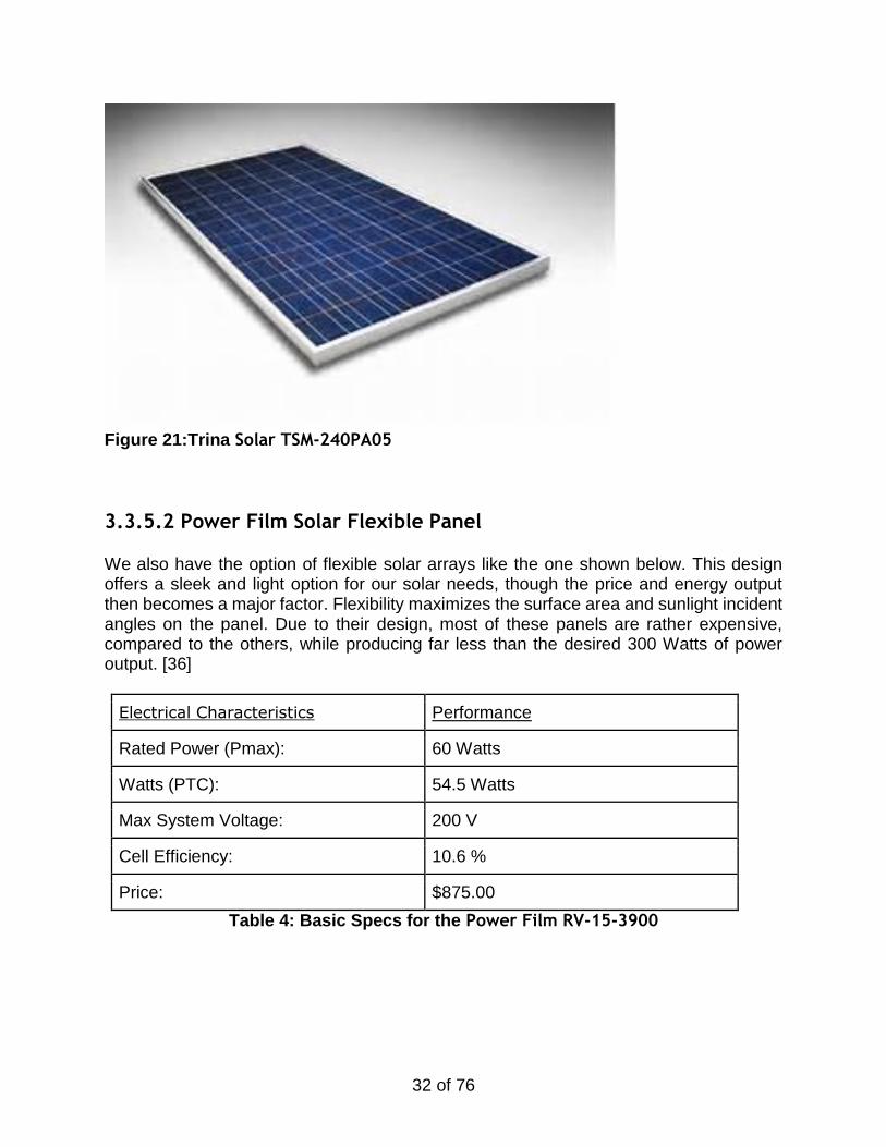
We could have a standard flat panel solar array that would be inexpensive and relatively easy to mount, though it would likely be rather unwieldy. The panels are usually large and not designed for optimal use of surface area; these are the solar panels most often used for home energy efficiency on residential and commercial roofing. Also, these panels mostly performing at lower power specs than desired. Source: [35] While this design is inexpensive, it is also inefficient in it’s use of the space on the panel. The photovoltaic cells are usually lower quality in this style. The amount of power output for the size of the panel is just not practical.
32 of 76
Figure 21:Trina Solar TSM-240PA05
3.3.5.2 Power Film Solar Flexible Panel We also have the option of flexible solar arrays like the one shown below. This design offers a sleek and light option for our solar needs, though the price and energy output then becomes a major factor. Flexibility maximizes the surface area and sunlight incident angles on the panel. Due to their design, most of these panels are rather expensive, compared to the others, while producing far less than the desired 300 Watts of power output. [36]
Electrical Characteristics Performance
Rated Power (Pmax): 60 Watts
Watts (PTC): 54.5 Watts
Max System Voltage: 200 V
Cell Efficiency: 10.6 %
Price: $875.00
Table 4: Basic Specs for the Power Film RV-15-3900
33 of 76
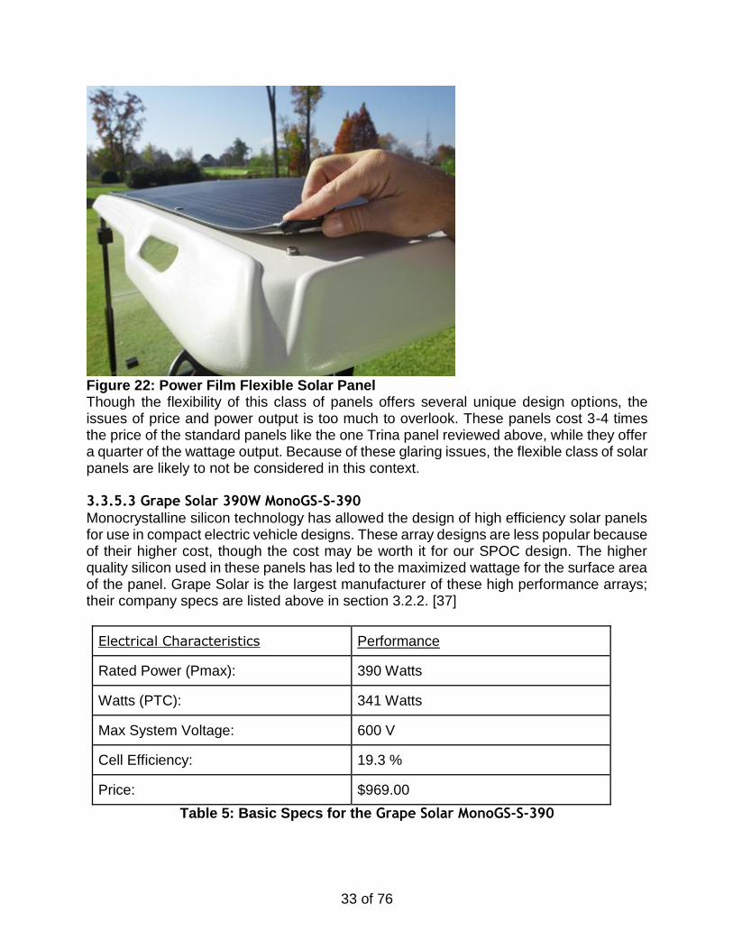
Figure 22: Power Film Flexible Solar Panel Though the flexibility of this class of panels offers several unique design options, the issues of price and power output is too much to overlook. These panels cost 3-4 times the price of the standard panels like the one Trina panel reviewed above, while they offer a quarter of the wattage output. Because of these glaring issues, the flexible class of solar panels are likely to not be considered in this context. 3.3.5.3 Grape Solar 390W MonoGS-S-390
Monocrystalline silicon technology has allowed the design of high efficiency solar panels for use in compact electric vehicle designs. These array designs are less popular because of their higher cost, though the cost may be worth it for our SPOC design. The higher quality silicon used in these panels has led to the maximized wattage for the surface area of the panel. Grape Solar is the largest manufacturer of these high performance arrays; their company specs are listed above in section 3.2.2. [37]
Electrical Characteristics Performance
Rated Power (Pmax): 390 Watts
Watts (PTC): 341 Watts
Max System Voltage: 600 V
Cell Efficiency: 19.3 %
Price: $969.00
Table 5: Basic Specs for the Grape Solar MonoGS-S-390
34 of 76
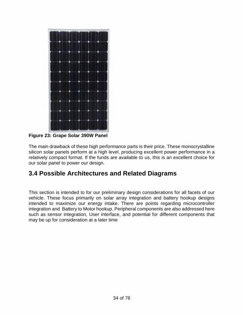
Figure 23: Grape Solar 390W Panel
The main drawback of these high performance parts is their price. These monocrystalline silicon solar panels perform at a high level, producing excellent power performance in a relatively compact format. If the funds are available to us, this is an excellent choice for our solar panel to power our design.
3.4 Possible Architectures and Related Diagrams
This section is intended to for our preliminary design considerations for all facets of our vehicle. These focus primarily on solar array integration and battery hookup designs intended to maximize our energy intake. There are points regarding microcontroller integration and Battery to Motor hookup. Peripheral components are also addressed here such as sensor integration, User interface, and potential for different components that may be up for consideration at a later time
35 of 76
3.4.1 Solar Array Architecture
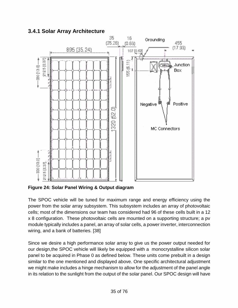
Figure 24: Solar Panel Wiring & Output diagram
The SPOC vehicle will be tuned for maximum range and energy efficiency using the
power from the solar array subsystem. This subsystem includes an array of photovoltaic
cells; most of the dimensions our team has considered had 96 of these cells built in a 12
x 8 configuration. These photovoltaic cells are mounted on a supporting structure; a pv
module typically includes a panel, an array of solar cells, a power inverter, interconnection
wiring, and a bank of batteries. [38]
Since we desire a high performance solar array to give us the power output needed for
our design,the SPOC vehicle will likely be equipped with a monocrystalline silicon solar
panel to be acquired in Phase 0 as defined below. These units come prebuilt in a design
similar to the one mentioned and displayed above. One specific architectural adjustment
we might make includes a hinge mechanism to allow for the adjustment of the panel angle
in its relation to the sunlight from the output of the solar panel. Our SPOC design will have
36 of 76
the output of the chosen solar panel connected to the power optimization unit within the
framework of the cart platform.
3.4.2 Motor, Battery, MicroController Integration
In this section we will display our designs and schematics for different parts of our design and how we intend to implement and integrate these parts. The primary components for our vehicle are the connection of the Photovoltaic cells to the battery, the battery connection to the motors,and the solar panel connection to the electric motors. [43] Microcontroller integration across these parts, and Microcontroller connection to the User Interface. All these are still in a design phase since we have not received all necessary parts yet. However these designs should give an accurate idea of what the intended end design will be and how we intend to go about implementing it.
3.4.2.1 3-terminal temperature sensor for Photovoltaic cells
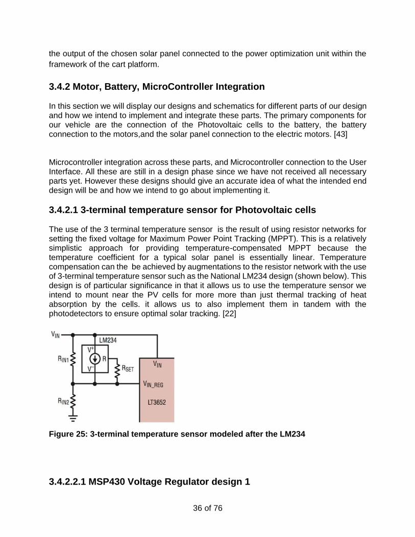
The use of the 3 terminal temperature sensor is the result of using resistor networks for setting the fixed voltage for Maximum Power Point Tracking (MPPT). This is a relatively simplistic approach for providing temperature-compensated MPPT because the temperature coefficient for a typical solar panel is essentially linear. Temperature compensation can the be achieved by augmentations to the resistor network with the use of 3-terminal temperature sensor such as the National LM234 design (shown below). This design is of particular significance in that it allows us to use the temperature sensor we intend to mount near the PV cells for more more than just thermal tracking of heat absorption by the cells. it allows us to also implement them in tandem with the photodetectors to ensure optimal solar tracking. [22]
Figure 25: 3-terminal temperature sensor modeled after the LM234
3.4.2.2.1 MSP430 Voltage Regulator design 1
37 of 76
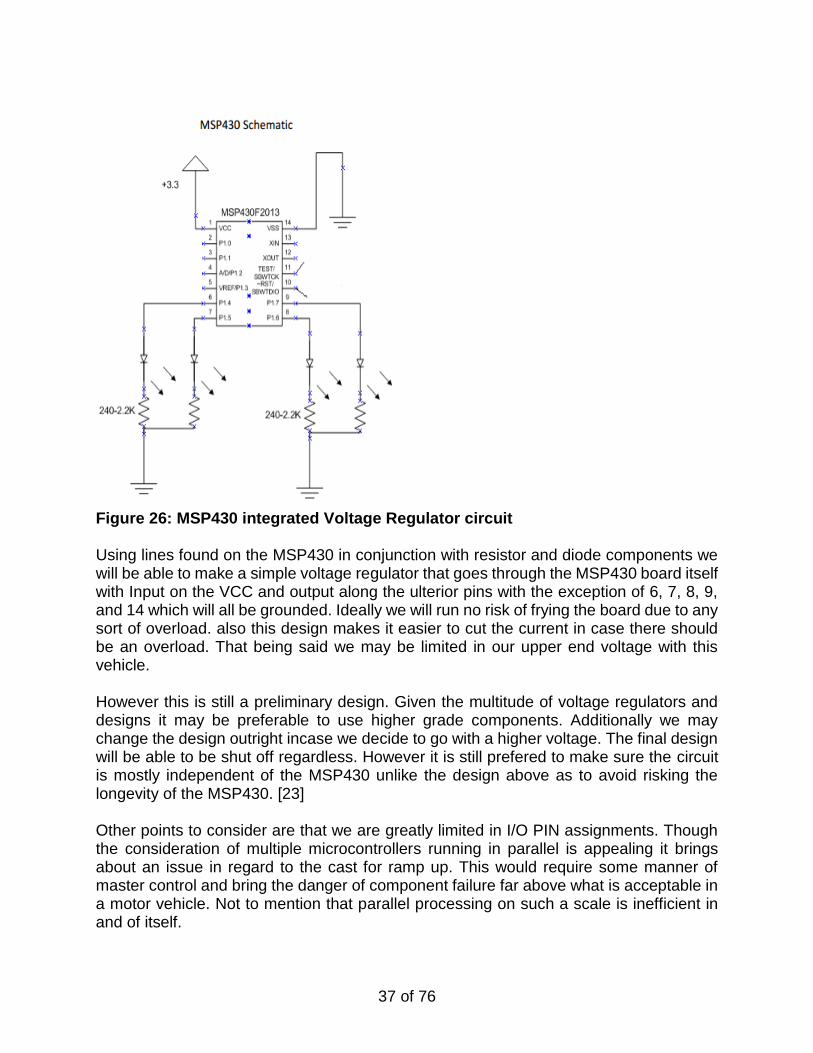
Figure 26: MSP430 integrated Voltage Regulator circuit Using lines found on the MSP430 in conjunction with resistor and diode components we will be able to make a simple voltage regulator that goes through the MSP430 board itself with Input on the VCC and output along the ulterior pins with the exception of 6, 7, 8, 9, and 14 which will all be grounded. Ideally we will run no risk of frying the board due to any sort of overload. also this design makes it easier to cut the current in case there should be an overload. That being said we may be limited in our upper end voltage with this vehicle. However this is still a preliminary design. Given the multitude of voltage regulators and designs it may be preferable to use higher grade components. Additionally we may change the design outright incase we decide to go with a higher voltage. The final design will be able to be shut off regardless. However it is still prefered to make sure the circuit is mostly independent of the MSP430 unlike the design above as to avoid risking the longevity of the MSP430. [23] Other points to consider are that we are greatly limited in I/O PIN assignments. Though the consideration of multiple microcontrollers running in parallel is appealing it brings about an issue in regard to the cast for ramp up. This would require some manner of master control and bring the danger of component failure far above what is acceptable in a motor vehicle. Not to mention that parallel processing on such a scale is inefficient in and of itself.
38 of 76
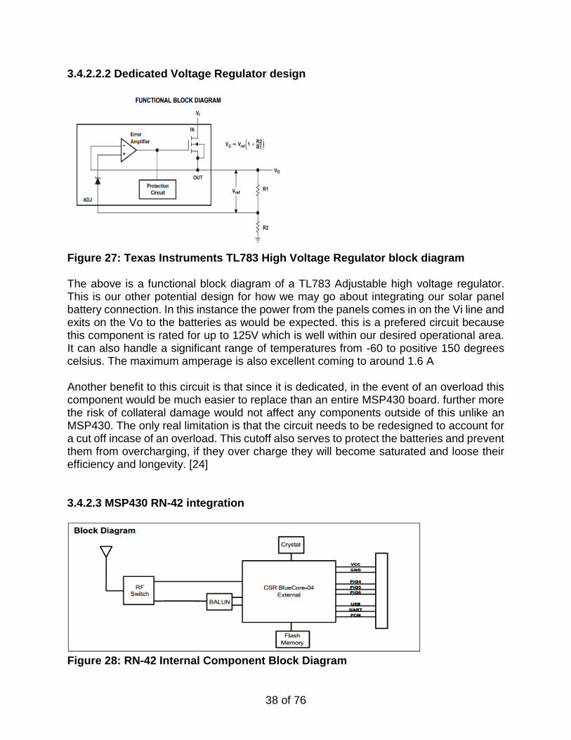
3.4.2.2.2 Dedicated Voltage Regulator design
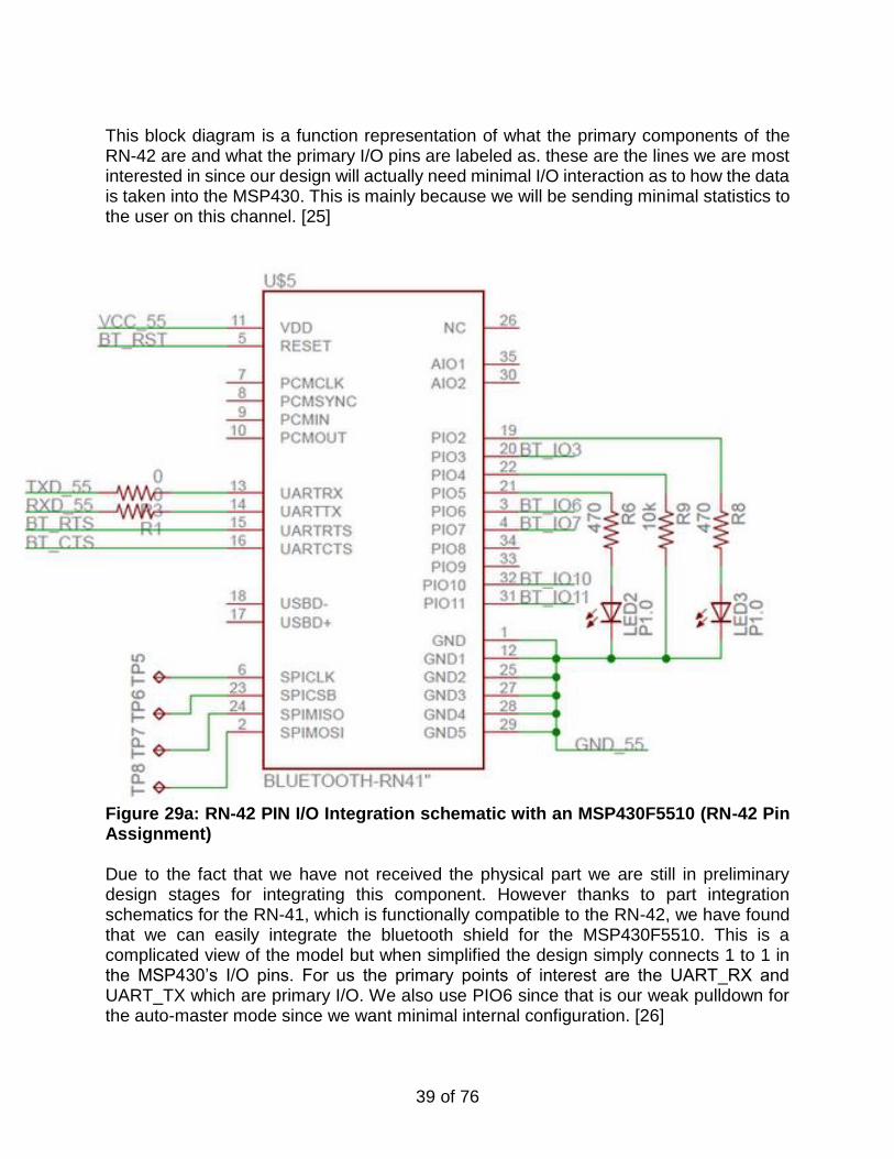
Figure 27: Texas Instruments TL783 High Voltage Regulator block diagram The above is a functional block diagram of a TL783 Adjustable high voltage regulator. This is our other potential design for how we may go about integrating our solar panel battery connection. In this instance the power from the panels comes in on the Vi line and exits on the Vo to the batteries as would be expected. this is a prefered circuit because this component is rated for up to 125V which is well within our desired operational area. It can also handle a significant range of temperatures from -60 to positive 150 degrees celsius. The maximum amperage is also excellent coming to around 1.6 A Another benefit to this circuit is that since it is dedicated, in the event of an overload this component would be much easier to replace than an entire MSP430 board. further more the risk of collateral damage would not affect any components outside of this unlike an MSP430. The only real limitation is that the circuit needs to be redesigned to account for a cut off incase of an overload. This cutoff also serves to protect the batteries and prevent them from overcharging, if they over charge they will become saturated and loose their efficiency and longevity. [24] 3.4.2.3 MSP430 RN-42 integration
Figure 28: RN-42 Internal Component Block Diagram
39 of 76
This block diagram is a function representation of what the primary components of the RN-42 are and what the primary I/O pins are labeled as. these are the lines we are most interested in since our design will actually need minimal I/O interaction as to how the data is taken into the MSP430. This is mainly because we will be sending minimal statistics to the user on this channel. [25]
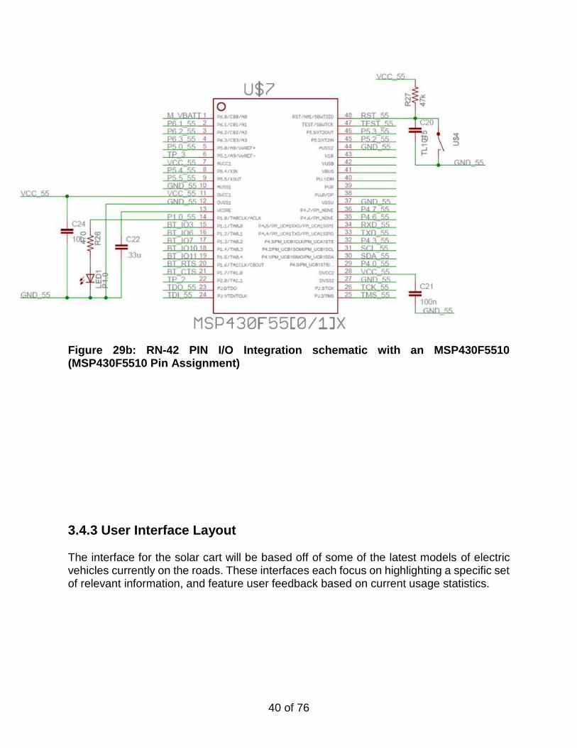
Figure 29a: RN-42 PIN I/O Integration schematic with an MSP430F5510 (RN-42 Pin Assignment) Due to the fact that we have not received the physical part we are still in preliminary design stages for integrating this component. However thanks to part integration schematics for the RN-41, which is functionally compatible to the RN-42, we have found that we can easily integrate the bluetooth shield for the MSP430F5510. This is a complicated view of the model but when simplified the design simply connects 1 to 1 in the MSP430’s I/O pins. For us the primary points of interest are the UART_RX and UART_TX which are primary I/O. We also use PIO6 since that is our weak pulldown for the auto-master mode since we want minimal internal configuration. [26]
40 of 76
Figure 29b: RN-42 PIN I/O Integration schematic with an MSP430F5510 (MSP430F5510 Pin Assignment)
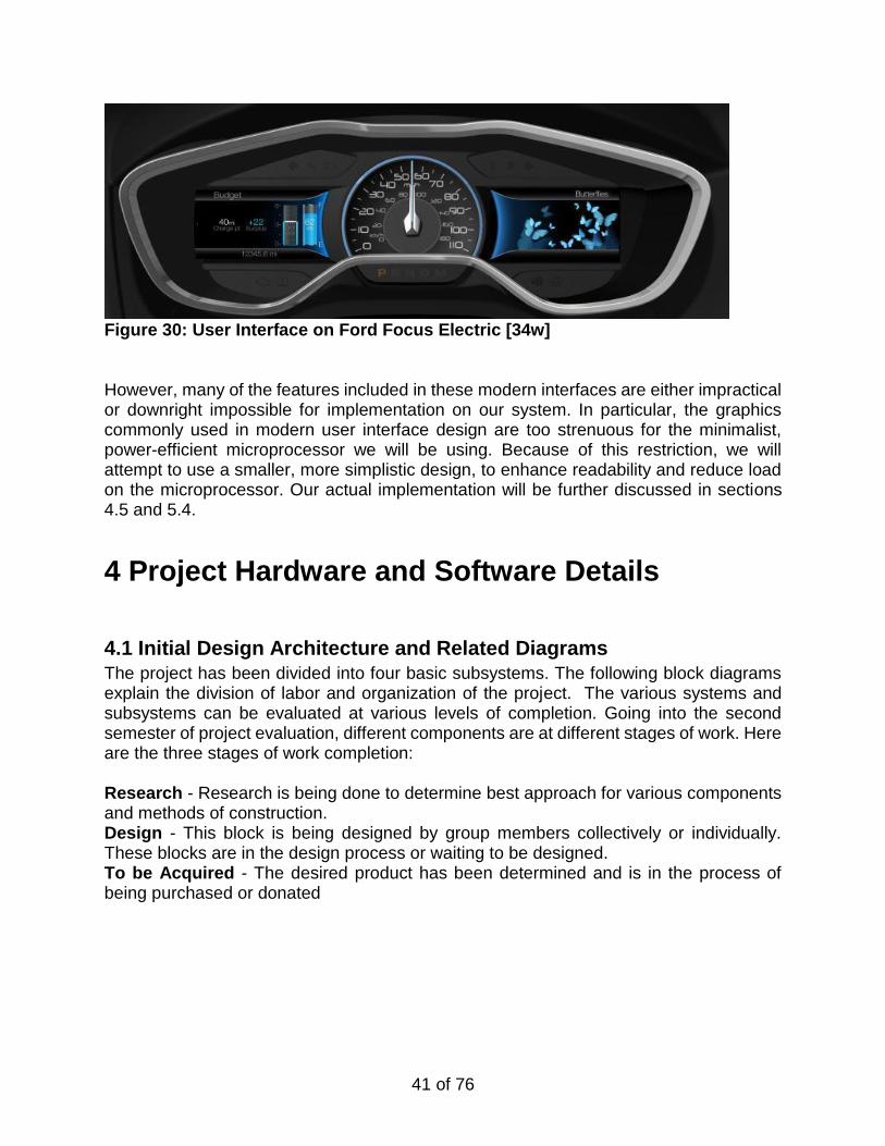
3.4.3 User Interface Layout The interface for the solar cart will be based off of some of the latest models of electric vehicles currently on the roads. These interfaces each focus on highlighting a specific set of relevant information, and feature user feedback based on current usage statistics.
41 of 76
Figure 30: User Interface on Ford Focus Electric [34w] However, many of the features included in these modern interfaces are either impractical or downright impossible for implementation on our system. In particular, the graphics commonly used in modern user interface design are too strenuous for the minimalist, power-efficient microprocessor we will be using. Because of this restriction, we will attempt to use a smaller, more simplistic design, to enhance readability and reduce load on the microprocessor. Our actual implementation will be further discussed in sections 4.5 and 5.4.
4 Project Hardware and Software Details
4.1 Initial Design Architecture and Related Diagrams
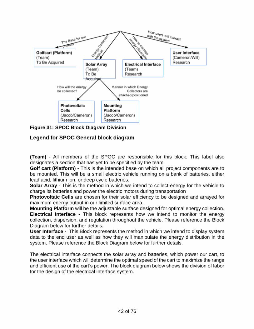
The project has been divided into four basic subsystems. The following block diagrams explain the division of labor and organization of the project. The various systems and subsystems can be evaluated at various levels of completion. Going into the second semester of project evaluation, different components are at different stages of work. Here are the three stages of work completion: Research - Research is being done to determine best approach for various components and methods of construction. Design - This block is being designed by group members collectively or individually. These blocks are in the design process or waiting to be designed. To be Acquired - The desired product has been determined and is in the process of being purchased or donated
42 of 76
Figure 31: SPOC Block Diagram Division
Legend for SPOC General block diagram
(Team) - All members of the SPOC are responsible for this block. This label also designates a section that has yet to be specified by the team. Golf cart (Platform) - This is the intended base on which all project components are to be mounted. This will be a small electric vehicle running on a bank of batteries, either lead acid, lithium ion, or deep cycle batteries. Solar Array - This is the method in which we intend to collect energy for the vehicle to charge its batteries and power the electric motors during transportation Photovoltaic Cells are chosen for their solar efficiency to be designed and arrayed for maximum energy output in our limited surface area. Mounting Platform will be the adjustable surface designed for optimal energy collection. Electrical Interface - This block represents how we intend to monitor the energy collection, dispersion, and regulation throughout the vehicle. Please reference the Block Diagram below for further details. User Interface - This Block represents the method in which we intend to display system data to the end user as well as how they will manipulate the energy distribution in the system. Please reference the Block Diagram below for further details. The electrical interface connects the solar array and batteries, which power our cart, to the user interface which will determine the optimal speed of the cart to maximize the range and efficient use of the cart’s power. The block diagram below shows the division of labor for the design of the electrical interface system.
43 of 76
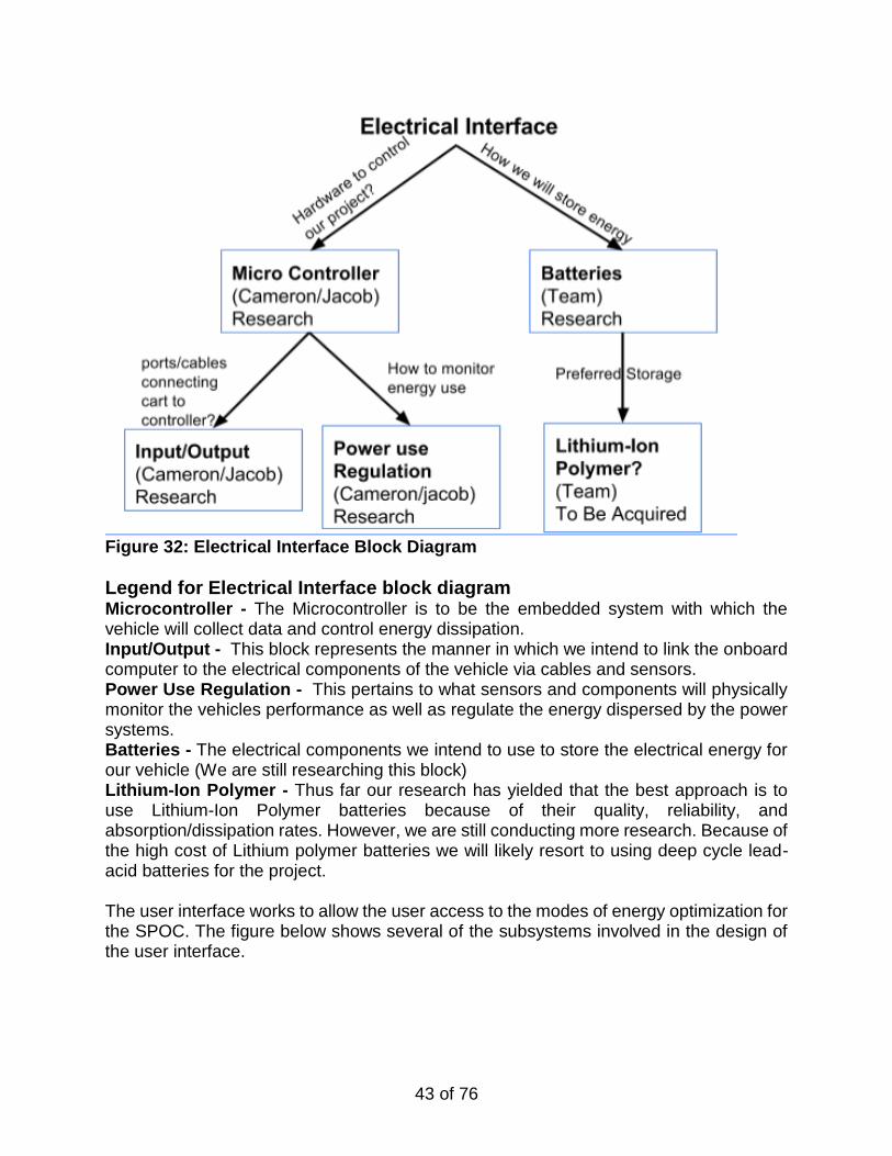
Figure 32: Electrical Interface Block Diagram
Legend for Electrical Interface block diagram Microcontroller - The Microcontroller is to be the embedded system with which the vehicle will collect data and control energy dissipation. Input/Output - This block represents the manner in which we intend to link the onboard computer to the electrical components of the vehicle via cables and sensors. Power Use Regulation - This pertains to what sensors and components will physically monitor the vehicles performance as well as regulate the energy dispersed by the power systems. Batteries - The electrical components we intend to use to store the electrical energy for our vehicle (We are still researching this block) Lithium-Ion Polymer - Thus far our research has yielded that the best approach is to use Lithium-Ion Polymer batteries because of their quality, reliability, and absorption/dissipation rates. However, we are still conducting more research. Because of the high cost of Lithium polymer batteries we will likely resort to using deep cycle lead-acid batteries for the project. The user interface works to allow the user access to the modes of energy optimization for the SPOC. The figure below shows several of the subsystems involved in the design of the user interface.
44 of 76
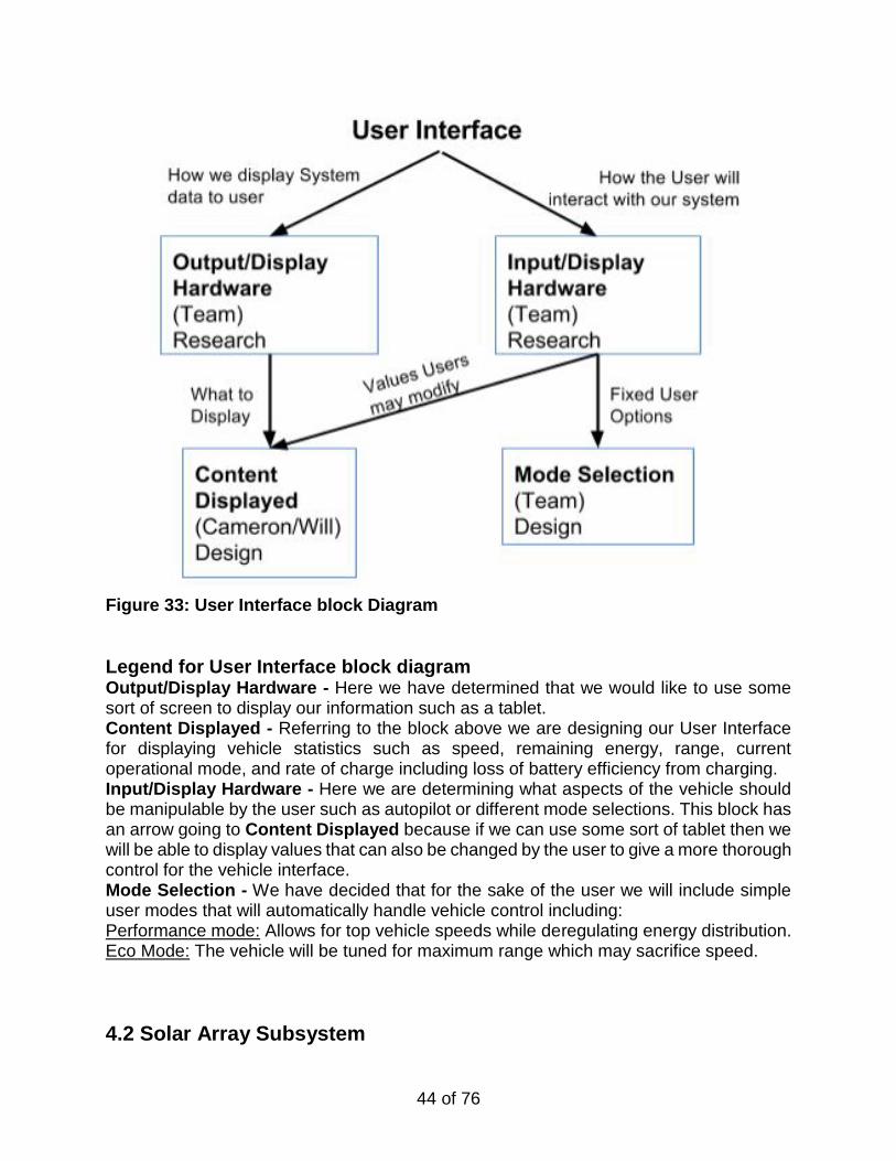
Figure 33: User Interface block Diagram
Legend for User Interface block diagram Output/Display Hardware - Here we have determined that we would like to use some sort of screen to display our information such as a tablet. Content Displayed - Referring to the block above we are designing our User Interface for displaying vehicle statistics such as speed, remaining energy, range, current operational mode, and rate of charge including loss of battery efficiency from charging. Input/Display Hardware - Here we are determining what aspects of the vehicle should be manipulable by the user such as autopilot or different mode selections. This block has an arrow going to Content Displayed because if we can use some sort of tablet then we will be able to display values that can also be changed by the user to give a more thorough control for the vehicle interface. Mode Selection - We have decided that for the sake of the user we will include simple user modes that will automatically handle vehicle control including: Performance mode: Allows for top vehicle speeds while deregulating energy distribution. Eco Mode: The vehicle will be tuned for maximum range which may sacrifice speed.
4.2 Solar Array Subsystem
45 of 76
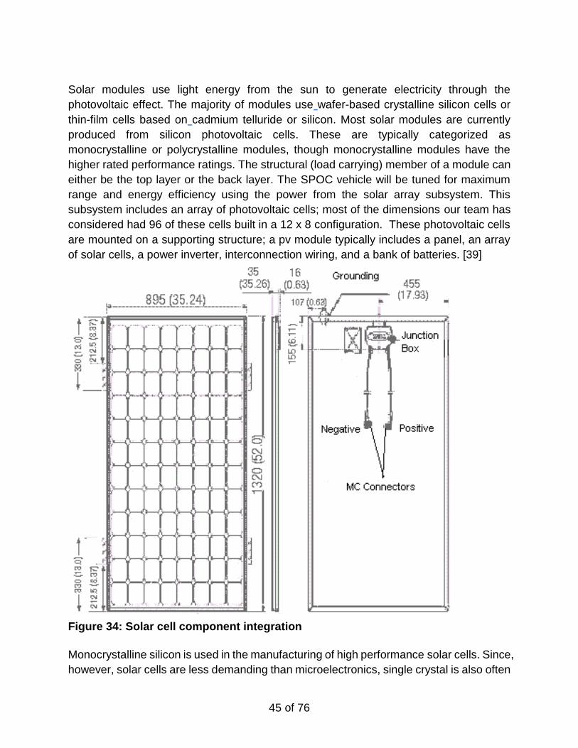
Solar modules use light energy from the sun to generate electricity through the
photovoltaic effect. The majority of modules use wafer-based crystalline silicon cells or
thin-film cells based on cadmium telluride or silicon. Most solar modules are currently
produced from silicon photovoltaic cells. These are typically categorized as
monocrystalline or polycrystalline modules, though monocrystalline modules have the
higher rated performance ratings. The structural (load carrying) member of a module can
either be the top layer or the back layer. The SPOC vehicle will be tuned for maximum
range and energy efficiency using the power from the solar array subsystem. This
subsystem includes an array of photovoltaic cells; most of the dimensions our team has
considered had 96 of these cells built in a 12 x 8 configuration. These photovoltaic cells
are mounted on a supporting structure; a pv module typically includes a panel, an array
of solar cells, a power inverter, interconnection wiring, and a bank of batteries. [39]
Figure 34: Solar cell component integration
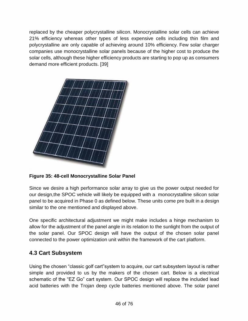
Monocrystalline silicon is used in the manufacturing of high performance solar cells. Since,
however, solar cells are less demanding than microelectronics, single crystal is also often
46 of 76
replaced by the cheaper polycrystalline silicon. Monocrystalline solar cells can achieve
21% efficiency whereas other types of less expensive cells including thin film and
polycrystalline are only capable of achieving around 10% efficiency. Few solar charger
companies use monocrystalline solar panels because of the higher cost to produce the
solar cells, although these higher efficiency products are starting to pop up as consumers
demand more efficient products. [39]
Figure 35: 48-cell Monocrystalline Solar Panel
Since we desire a high performance solar array to give us the power output needed for
our design,the SPOC vehicle will likely be equipped with a monocrystalline silicon solar
panel to be acquired in Phase 0 as defined below. These units come pre built in a design
similar to the one mentioned and displayed above.
One specific architectural adjustment we might make includes a hinge mechanism to
allow for the adjustment of the panel angle in its relation to the sunlight from the output of
the solar panel. Our SPOC design will have the output of the chosen solar panel
connected to the power optimization unit within the framework of the cart platform.
4.3 Cart Subsystem
Using the chosen “classic golf cart”system to acquire, our cart subsystem layout is rather
simple and provided to us by the makers of the chosen cart. Below is a electrical
schematic of the “EZ Go” cart system. Our SPOC design will replace the included lead
acid batteries with the Trojan deep cycle batteries mentioned above. The solar panel
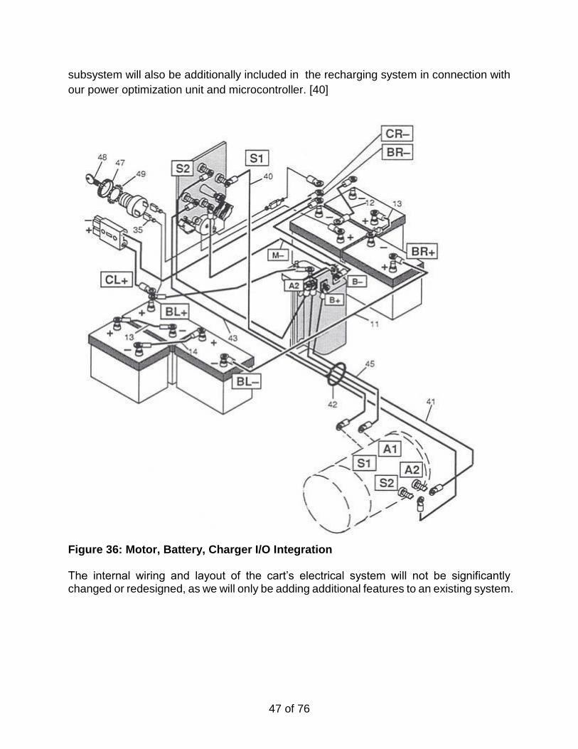
47 of 76
subsystem will also be additionally included in the recharging system in connection with
our power optimization unit and microcontroller. [40]
Figure 36: Motor, Battery, Charger I/O Integration The internal wiring and layout of the cart’s electrical system will not be significantly changed or redesigned, as we will only be adding additional features to an existing system.
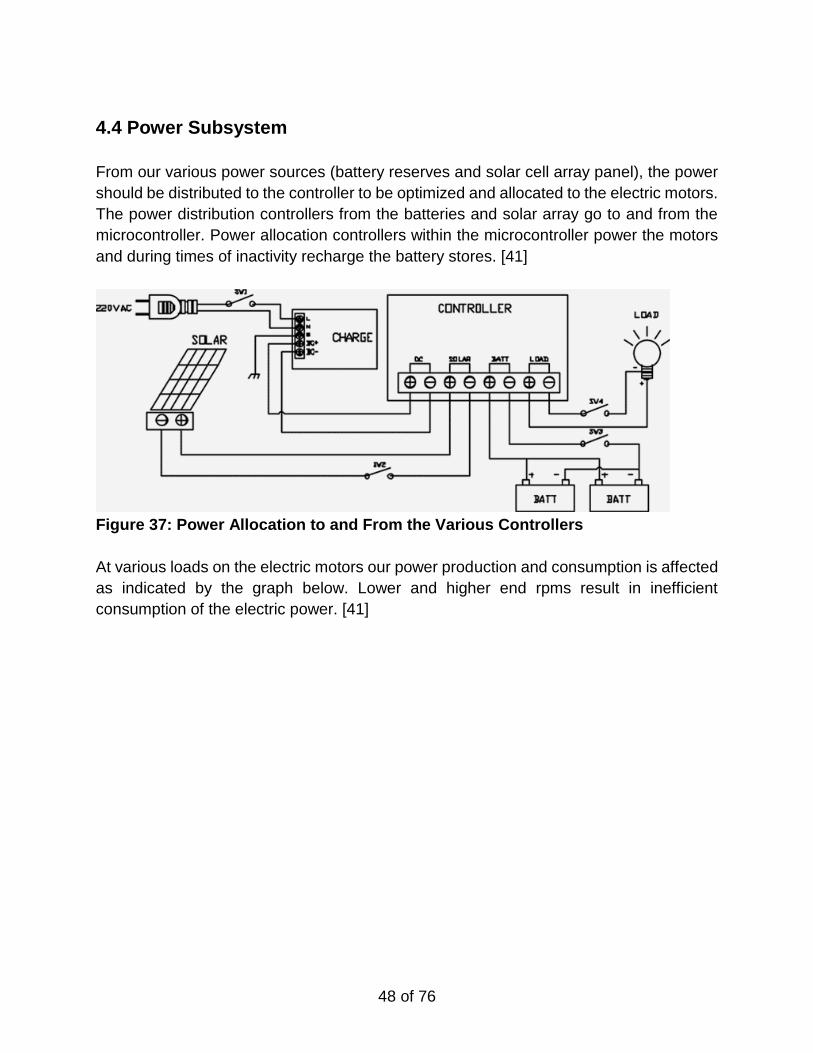
48 of 76
4.4 Power Subsystem
From our various power sources (battery reserves and solar cell array panel), the power
should be distributed to the controller to be optimized and allocated to the electric motors.
The power distribution controllers from the batteries and solar array go to and from the
microcontroller. Power allocation controllers within the microcontroller power the motors
and during times of inactivity recharge the battery stores. [41]
Figure 37: Power Allocation to and From the Various Controllers
At various loads on the electric motors our power production and consumption is affected
as indicated by the graph below. Lower and higher end rpms result in inefficient
consumption of the electric power. [41]
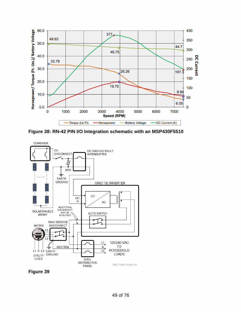
49 of 76
Figure 38: RN-42 PIN I/O Integration schematic with an MSP430F5510
Figure 39
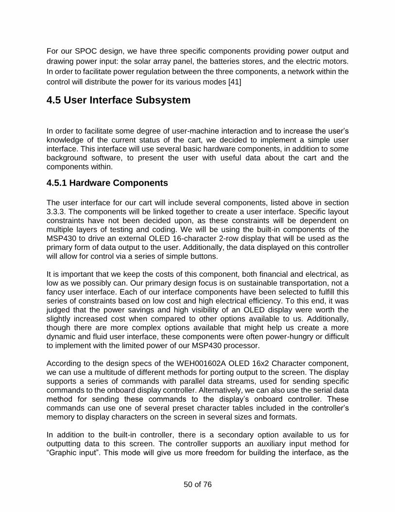
50 of 76
For our SPOC design, we have three specific components providing power output and
drawing power input: the solar array panel, the batteries stores, and the electric motors.
In order to facilitate power regulation between the three components, a network within the
control will distribute the power for its various modes [41]
4.5 User Interface Subsystem
In order to facilitate some degree of user-machine interaction and to increase the user’s knowledge of the current status of the cart, we decided to implement a simple user interface. This interface will use several basic hardware components, in addition to some background software, to present the user with useful data about the cart and the components within.
4.5.1 Hardware Components
The user interface for our cart will include several components, listed above in section 3.3.3. The components will be linked together to create a user interface. Specific layout constraints have not been decided upon, as these constraints will be dependent on multiple layers of testing and coding. We will be using the built-in components of the MSP430 to drive an external OLED 16-character 2-row display that will be used as the primary form of data output to the user. Additionally, the data displayed on this controller will allow for control via a series of simple buttons. It is important that we keep the costs of this component, both financial and electrical, as low as we possibly can. Our primary design focus is on sustainable transportation, not a fancy user interface. Each of our interface components have been selected to fulfill this series of constraints based on low cost and high electrical efficiency. To this end, it was judged that the power savings and high visibility of an OLED display were worth the slightly increased cost when compared to other options available to us. Additionally, though there are more complex options available that might help us create a more dynamic and fluid user interface, these components were often power-hungry or difficult to implement with the limited power of our MSP430 processor. According to the design specs of the WEH001602A OLED 16x2 Character component, we can use a multitude of different methods for porting output to the screen. The display supports a series of commands with parallel data streams, used for sending specific commands to the onboard display controller. Alternatively, we can also use the serial data method for sending these commands to the display’s onboard controller. These commands can use one of several preset character tables included in the controller’s memory to display characters on the screen in several sizes and formats. In addition to the built-in controller, there is a secondary option available to us for outputting data to this screen. The controller supports an auxiliary input method for “Graphic input”. This mode will give us more freedom for building the interface, as the
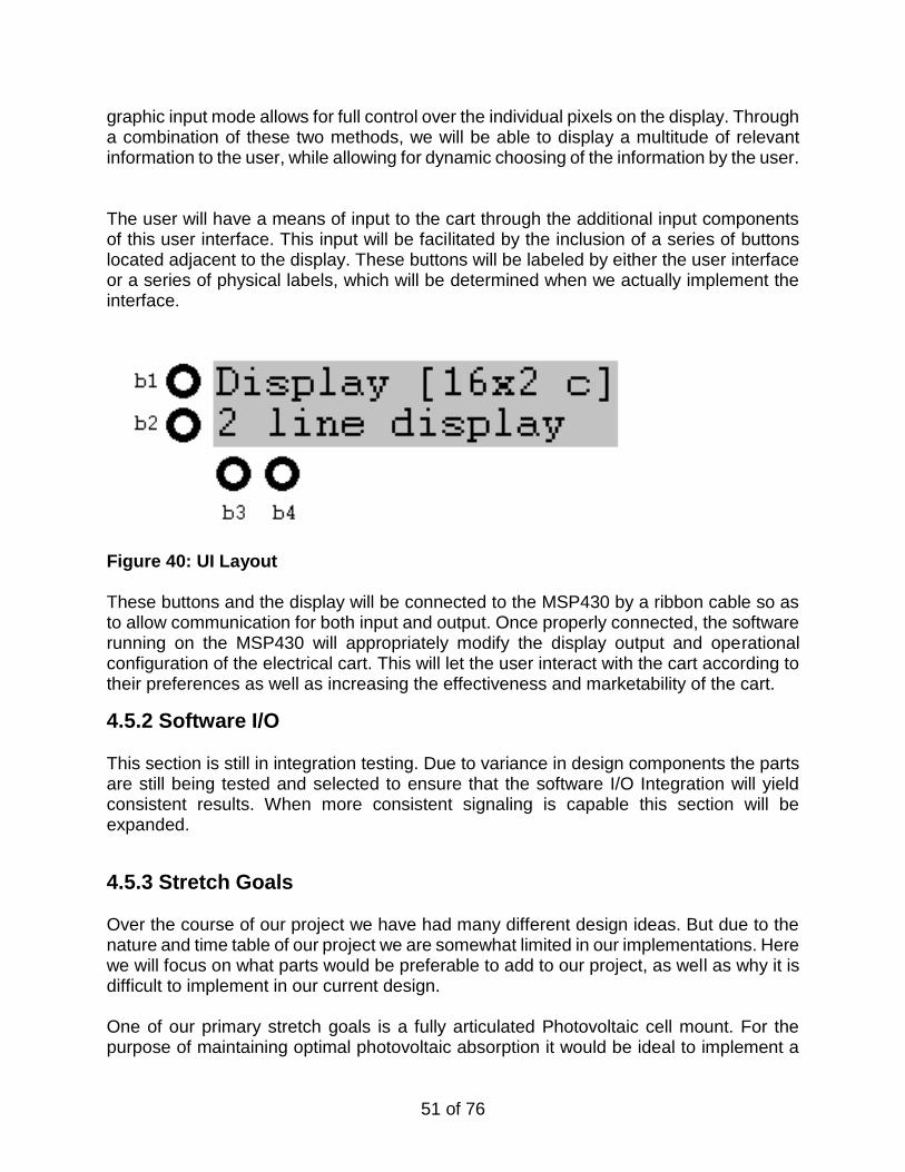
51 of 76
graphic input mode allows for full control over the individual pixels on the display. Through a combination of these two methods, we will be able to display a multitude of relevant information to the user, while allowing for dynamic choosing of the information by the user. The user will have a means of input to the cart through the additional input components of this user interface. This input will be facilitated by the inclusion of a series of buttons located adjacent to the display. These buttons will be labeled by either the user interface or a series of physical labels, which will be determined when we actually implement the interface.
Figure 40: UI Layout These buttons and the display will be connected to the MSP430 by a ribbon cable so as to allow communication for both input and output. Once properly connected, the software running on the MSP430 will appropriately modify the display output and operational configuration of the electrical cart. This will let the user interact with the cart according to their preferences as well as increasing the effectiveness and marketability of the cart.
4.5.2 Software I/O This section is still in integration testing. Due to variance in design components the parts are still being tested and selected to ensure that the software I/O Integration will yield consistent results. When more consistent signaling is capable this section will be expanded.
4.5.3 Stretch Goals Over the course of our project we have had many different design ideas. But due to the nature and time table of our project we are somewhat limited in our implementations. Here we will focus on what parts would be preferable to add to our project, as well as why it is difficult to implement in our current design. One of our primary stretch goals is a fully articulated Photovoltaic cell mount. For the purpose of maintaining optimal photovoltaic absorption it would be ideal to implement a
52 of 76
mounting system with at least two points of articulation. The mount would rotate along the x-axis (left to right) and the z-axis (front to back) with up to 30 degrees of freedom. Furthermore it might be able to rotate in a circular manner around the y-axis with another ninety degrees of freedom. The primary limitation with this goal is weight. A system with the dexterity described would double the weight of the PV mounting if not triple it. Additionally the entire assembly would require the onboard computer (MSP430) to be on consistently for solar tracking. Between the motors and microcontroller there would be a certain amount of electrical and computational overhead. This would limit the total efficiency of the system, and hinder charging due to the amount of electrical energy needed to keep the systems consistently operating. Another primary stretch goal for us is the implementation of GPS. There are many GPS enabled microcontrollers and MSP430 GPS adapters. By adding accurate, functional GPS our vehicle could optimize travel patterns over terrain. It would also allow the vehicle to maintain travel data so that it could inform the user when it was dissipating more energy than it would need to get back. The limitation for this goal is that it is inefficient for us to implement GPS on any of our currently intended MSP430 models. This is due to the computational overhead of persistently tracking vehicle position. It also requires the use of I/O pins that will be accommodating a host of other components that are far more important for proper vehicle functionality. The alternative to these limitations is to acquire another microcontroller that is dedicated to GPS tracking. However the issue then becomes how to have the microcontrollers communicate, what data needs to be sent, and in this case cost and energy overhead can still be an issue given our tight budget. Our final stretch goal, though currently intended to be part of our final product, is full bluetooth integration. In energy conservation projects displaying as much data as possible can help not only the vehicle but the user. Considering how bluetooth technology can allow a user to fully interact with their car, we believe a similar approach could improve customer experience when Operating the SPOC. As a minimum we hope to implement a simplistic User Interface that allow vehicle drive mode selection, and limited setting customization. This includes adjust speed boundaries for the different modes. However it would be preferred to also keep up-to-date visual data tracking of vehicle performance, charge dissipation, vehicle efficiency, the aforementioned settings, and component longevity when possible (primarily battery replacement). Such information would also be displayed on the local console which would bring a certain modern design and appeal to our project. The limitation to full bluetooth functionality is primarily time. Our projects focus is optimized solar powered vehicular travel. Creating a custom User Interface to accommodate this data and graphical information may be beyond the scope of our project. Further more having this amount of usage data being transmitted over bluetooth could cause heavy computational overhead for our onboard microcontroller. Finally, to have the
53 of 76
intended degree of control, certain custom modules would have to be designed for our project. These modules would otherwise be superfluous, so we must carefully judge our available time and funds to best decide which modules to implement.
5 Design Summary of Hardware and Software
This section focuses on how components from the project will be integrated as a whole. The primary components of this system are the Photovoltaic cells connection to the battery assembly. The remainder connection is battery connection to the motors, and finally the microcontroller overlay. The microcontroller sensor connections are also an important aspect of the overall maintenance of the vehicle but not as crucial as these 2 primary components. Other points of interest are User interface. This includes both the LCD integration, and bluetooth integration designs. Finally this section will also cover the basics of vehicle design and usage modeling. this includes the vehicles expected performance mode and also a brief look at the expected performance boundaries of our vehicle.
5.1 Solar Cell Charge System
The solar cell charge system transfer the power from the array of photovoltaics cells in one of two possible direction. The solar charging system can transfer power to the electric motors during use in transportation or the converted solar power can be delivered to the batteries to recharge them during period of system rest. This system will be regulated by the microcontroller. [50]
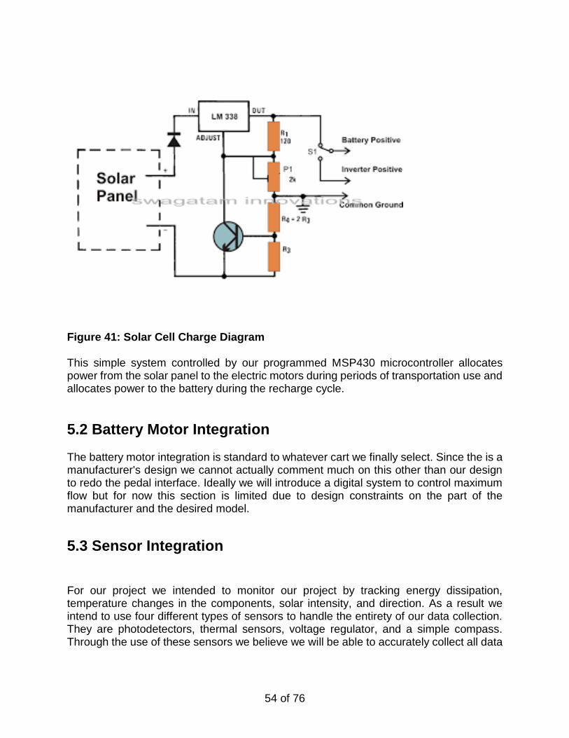
54 of 76
Figure 41: Solar Cell Charge Diagram This simple system controlled by our programmed MSP430 microcontroller allocates power from the solar panel to the electric motors during periods of transportation use and allocates power to the battery during the recharge cycle.
5.2 Battery Motor Integration
The battery motor integration is standard to whatever cart we finally select. Since the is a manufacturer's design we cannot actually comment much on this other than our design to redo the pedal interface. Ideally we will introduce a digital system to control maximum flow but for now this section is limited due to design constraints on the part of the manufacturer and the desired model.
5.3 Sensor Integration
For our project we intended to monitor our project by tracking energy dissipation, temperature changes in the components, solar intensity, and direction. As a result we intend to use four different types of sensors to handle the entirety of our data collection. They are photodetectors, thermal sensors, voltage regulator, and a simple compass. Through the use of these sensors we believe we will be able to accurately collect all data
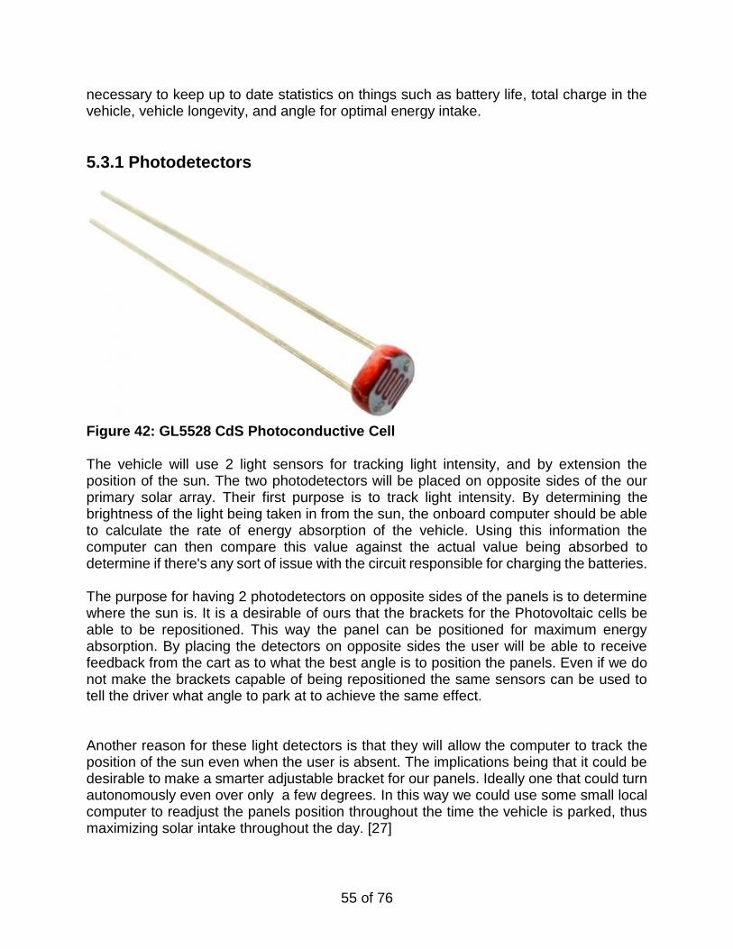
55 of 76
necessary to keep up to date statistics on things such as battery life, total charge in the vehicle, vehicle longevity, and angle for optimal energy intake.
5.3.1 Photodetectors
Figure 42: GL5528 CdS Photoconductive Cell The vehicle will use 2 light sensors for tracking light intensity, and by extension the position of the sun. The two photodetectors will be placed on opposite sides of the our primary solar array. Their first purpose is to track light intensity. By determining the brightness of the light being taken in from the sun, the onboard computer should be able to calculate the rate of energy absorption of the vehicle. Using this information the computer can then compare this value against the actual value being absorbed to determine if there's any sort of issue with the circuit responsible for charging the batteries. The purpose for having 2 photodetectors on opposite sides of the panels is to determine where the sun is. It is a desirable of ours that the brackets for the Photovoltaic cells be able to be repositioned. This way the panel can be positioned for maximum energy absorption. By placing the detectors on opposite sides the user will be able to receive feedback from the cart as to what the best angle is to position the panels. Even if we do not make the brackets capable of being repositioned the same sensors can be used to tell the driver what angle to park at to achieve the same effect. Another reason for these light detectors is that they will allow the computer to track the position of the sun even when the user is absent. The implications being that it could be desirable to make a smarter adjustable bracket for our panels. Ideally one that could turn autonomously even over only a few degrees. In this way we could use some small local computer to readjust the panels position throughout the time the vehicle is parked, thus maximizing solar intake throughout the day. [27]
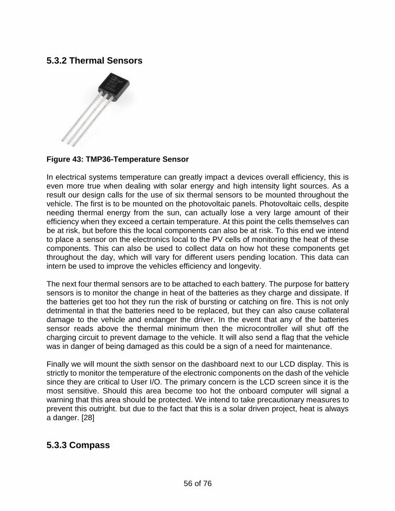
56 of 76
5.3.2 Thermal Sensors
Figure 43: TMP36-Temperature Sensor In electrical systems temperature can greatly impact a devices overall efficiency, this is even more true when dealing with solar energy and high intensity light sources. As a result our design calls for the use of six thermal sensors to be mounted throughout the vehicle. The first is to be mounted on the photovoltaic panels. Photovoltaic cells, despite needing thermal energy from the sun, can actually lose a very large amount of their efficiency when they exceed a certain temperature. At this point the cells themselves can be at risk, but before this the local components can also be at risk. To this end we intend to place a sensor on the electronics local to the PV cells of monitoring the heat of these components. This can also be used to collect data on how hot these components get throughout the day, which will vary for different users pending location. This data can intern be used to improve the vehicles efficiency and longevity.
The next four thermal sensors are to be attached to each battery. The purpose for battery sensors is to monitor the change in heat of the batteries as they charge and dissipate. If the batteries get too hot they run the risk of bursting or catching on fire. This is not only detrimental in that the batteries need to be replaced, but they can also cause collateral damage to the vehicle and endanger the driver. In the event that any of the batteries sensor reads above the thermal minimum then the microcontroller will shut off the charging circuit to prevent damage to the vehicle. It will also send a flag that the vehicle was in danger of being damaged as this could be a sign of a need for maintenance. Finally we will mount the sixth sensor on the dashboard next to our LCD display. This is strictly to monitor the temperature of the electronic components on the dash of the vehicle since they are critical to User I/O. The primary concern is the LCD screen since it is the most sensitive. Should this area become too hot the onboard computer will signal a warning that this area should be protected. We intend to take precautionary measures to prevent this outright. but due to the fact that this is a solar driven project, heat is always a danger. [28]
5.3.3 Compass
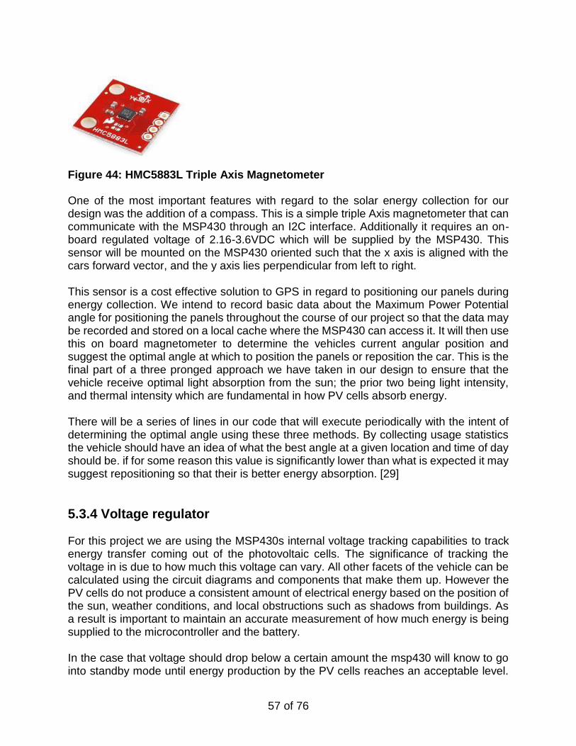
57 of 76
Figure 44: HMC5883L Triple Axis Magnetometer One of the most important features with regard to the solar energy collection for our design was the addition of a compass. This is a simple triple Axis magnetometer that can communicate with the MSP430 through an I2C interface. Additionally it requires an on-board regulated voltage of 2.16-3.6VDC which will be supplied by the MSP430. This sensor will be mounted on the MSP430 oriented such that the x axis is aligned with the cars forward vector, and the y axis lies perpendicular from left to right. This sensor is a cost effective solution to GPS in regard to positioning our panels during energy collection. We intend to record basic data about the Maximum Power Potential angle for positioning the panels throughout the course of our project so that the data may be recorded and stored on a local cache where the MSP430 can access it. It will then use this on board magnetometer to determine the vehicles current angular position and suggest the optimal angle at which to position the panels or reposition the car. This is the final part of a three pronged approach we have taken in our design to ensure that the vehicle receive optimal light absorption from the sun; the prior two being light intensity, and thermal intensity which are fundamental in how PV cells absorb energy. There will be a series of lines in our code that will execute periodically with the intent of determining the optimal angle using these three methods. By collecting usage statistics the vehicle should have an idea of what the best angle at a given location and time of day should be. if for some reason this value is significantly lower than what is expected it may suggest repositioning so that their is better energy absorption. [29]
5.3.4 Voltage regulator
For this project we are using the MSP430s internal voltage tracking capabilities to track energy transfer coming out of the photovoltaic cells. The significance of tracking the voltage in is due to how much this voltage can vary. All other facets of the vehicle can be calculated using the circuit diagrams and components that make them up. However the PV cells do not produce a consistent amount of electrical energy based on the position of the sun, weather conditions, and local obstructions such as shadows from buildings. As a result is important to maintain an accurate measurement of how much energy is being supplied to the microcontroller and the battery. In the case that voltage should drop below a certain amount the msp430 will know to go into standby mode until energy production by the PV cells reaches an acceptable level.
58 of 76
In this way the photodetectors and voltage regulator will be working in tandem as a redundant system to ensure that the MSP430 receives accurate input data. It is crucial that the amount of energy entering the batteries be monitored so that the system knows when the batteries are fully charged so that the input circuit can be shut off, furthering the longevity of the batteries. Additionally, the MSP430 must maintain as much accurate data as possible in regard to the amount of energy in the vehicle to ensure that all vehicle mode calculations are as efficient as possible. It may be beneficial to add voltmeters to the more peripheral components of the system such as the UI and also on the motor lines. This is strictly to gather more accurate vehicle data. As a whole the vehicle will not need anymore than the MSP430s voltage regulation of the energy into the system. However as stated prior, redundant monitoring systems are beneficial when dealing with a machine that needs to operate as consistently and efficiently as the SPOC.
5.4 User Interface
The user interface consists of a series of hardware modules used for input and output, as well as some software designed to run on the MSP430 microprocessor.
5.5 Vehicle Mode Modeling
This phase is still in its preliminary design phase so we have no actual code since we still need all necessary components to demonstrate the environment and actual I/O control. However our intent for the modeling modes as will be explained is to produce three different drive settings: Performance mode, Normal mode, and Eco mode. All these will work off the internal computer in the vehicle and affect different aspects of the vehicle such as range, top speed, and power dissipation. Our hope is to have all these facets working with Bluetooth and GPS integration. This way both the user and the vehicle will be able to keep the most up to date statistics on the vehicles performance and when components may need to be replaced.
5.5.1 Normal Mode Normal mode is just as it suggests. In this instance all vehicle components will behave as they normally would in the absence of any supervising software. For normal mode the on board computer will simply manage functions that are integral to the carts operation; these include: energy dissipation oversight, energy collection oversight, and top speed control.
59 of 76
The purpose of overseeing the energy dissipation and collection is to ensure that the carts components are operating efficiently and within tolerable standards. As stated before a common danger with electric vehicles is poorly supervised energy transfer. Unregulated, this behavior can drastically affect the vehicles performance over the course of its lifetime. It can also put the cart in danger of overheating and catching fire. The other aspect (limited top speed) simply limits vehicle speeds to what would typically be expected of the cart by its manufacturer. This way the cart is operating within expected norms so the risk for the priorly stated dangers is at a minimum but can still be present when dealing with such a dynamic system.
5.5.2 Performance Mode
In performance mode the vehicle’s monitoring will no longer limit top speed like in the Normal mode. Here the goal is maximum speed with minimum regard to power efficiency. The on board computers focus will be to push as much energy into the motors while staying within tolerable limits. To reiterate this means that the only limiting factor is the temperature of the components. Should a case arise where the vehicles energy output is causing too much heat production, the on board computer will take precautionary measures such as limiting the top speed, or cutting power to the motors all together. Ideally there will not be a situation where power to the engines must be cut but the focus of our project is to make the most powerful and energy efficient vehicle possible. Since the vehicle does still need to perform properly, we intend to include a limiter in the UI that will switch the performance mode back to normal mode. Ideally this will be an adjustable percentage so that the user can select how hard they wish to push the system. This limiter will have a baseline of 25% to ensure that their is ideally enough charge for the return trip since it would be prefered to make it home. A desirable for this limiter to integrate it with an onboard gps system. The user will be able to use the system to specify where “home” is and then the vehicle will calculate if it is able to return home based on its current location and energy supply. this way users will never have to concern themselves with whether or not they are able to return home.
5.5.3 Eco Mode In Eco (economical) mode the vehicle’s entire functionality based solely around traveling as efficiently as possible. To do this the computer will calculate the most energy efficient top speed so that the vehicle can achieve maximum range. For practical purposes we intend to implement a low end for this mode that limits speed to no lower than 6 mph. Referring back to the desired GPS implementation, GPS could drastically improve the vehicles drive ability by calculating the distance it had to travel between its current location and its desired location. This way the cart could be set to calculate the desired top speed so that it can reach the target destination while using maximum power dissipation. It would
60 of 76
also communicate with your bluetooth device (ideally gps enabled phone) to determine the optimal path for mapping and getting to your destination. Again the system is a desirable as it would need at least on board bluetooth and possibly on board GPS to work properly.
5.5.4 Limitations to these modes (weight, battery life, terrain) The greatest limitations to this system are weight, battery life and terrain. In order to get the most accurate measurements of how far the vehicle can travel, all accurate traversal algorithms require the total weight of the vehicle. This is can be guessed by the user but is harder to determine by the on board computer due to the frequency and manner in which it must be recalculated. Battery life is a problem because of how batteries lose their charge over the course of their lifetime. Our system intends to compensate for this lose based on common statistics put out by the manufacturer. This way the computer would have a constant estimate of what its maximum total power and best method for dissipation is. However this is still an estimate as no two batteries are ever exactly the same in practice, nor do the diminish at exactly the same rate. Still this will allow for calculations within a tolerable margin of error, and to provide the user on information as to when it would be best to replace battery their batteries. The final limitation is only a serious issue in case of GPS implementation. Though GPS can provide the distance between 2 locations, there is still the problem of the difference in altitude between two locations. Though GPS may focus strictly on mapping paths based on roads, the lack of compensation for inclines can have a drastic effect on the total range of an electric vehicle especially combined with differences in weight.
6.1 Part Acquisition and Bill of Materials
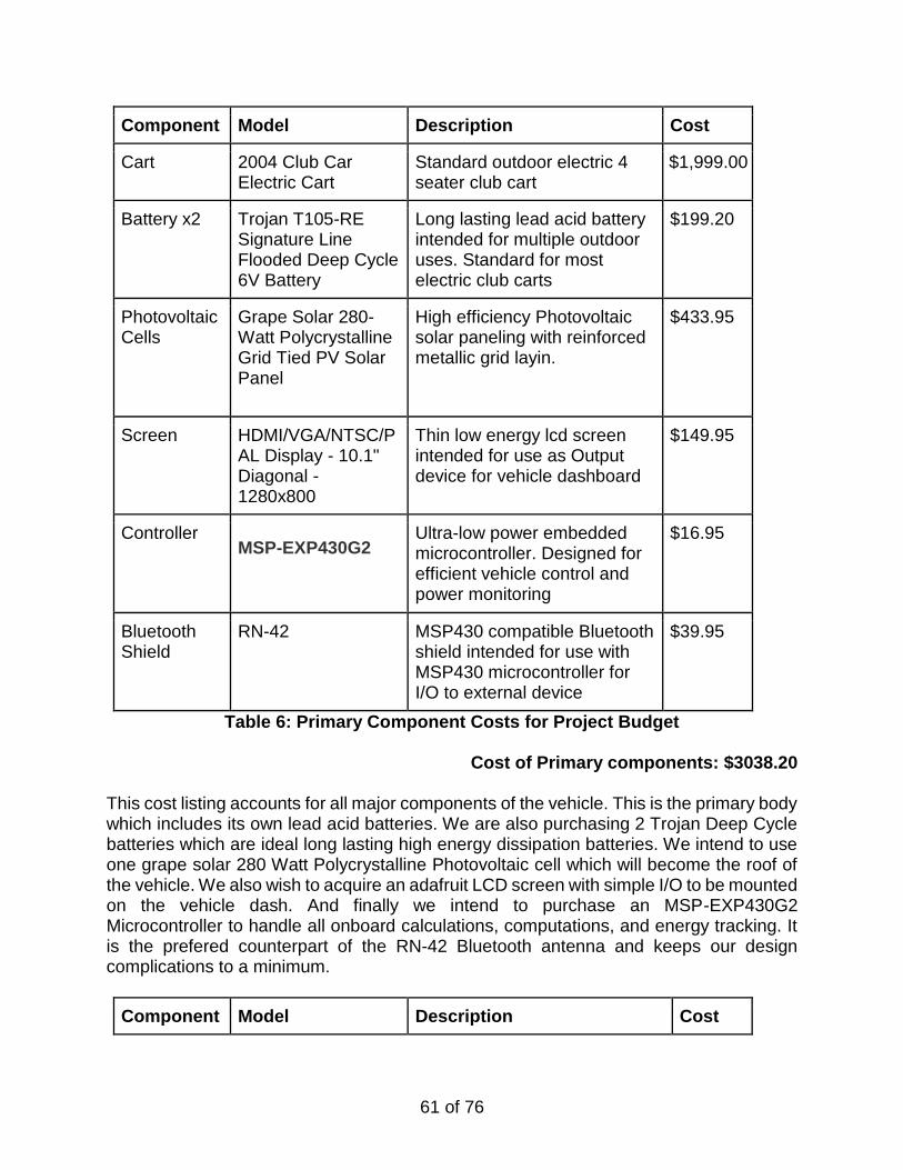
61 of 76
Component Model Description Cost
Cart 2004 Club Car Electric Cart
Standard outdoor electric 4 seater club cart
$1,999.00
Battery x2 Trojan T105-RE Signature Line Flooded Deep Cycle 6V Battery
Long lasting lead acid battery intended for multiple outdoor uses. Standard for most electric club carts
$199.20
Photovoltaic Cells
Grape Solar 280-Watt Polycrystalline Grid Tied PV Solar Panel
High efficiency Photovoltaic solar paneling with reinforced metallic grid layin.
$433.95
Screen HDMI/VGA/NTSC/PAL Display - 10.1" Diagonal - 1280x800
Thin low energy lcd screen intended for use as Output device for vehicle dashboard
$149.95
Controller MSP-EXP430G2
Ultra-low power embedded microcontroller. Designed for efficient vehicle control and power monitoring
$16.95
Bluetooth Shield
RN-42 MSP430 compatible Bluetooth shield intended for use with MSP430 microcontroller for I/O to external device
$39.95
Table 6: Primary Component Costs for Project Budget
Cost of Primary components: $3038.20 This cost listing accounts for all major components of the vehicle. This is the primary body which includes its own lead acid batteries. We are also purchasing 2 Trojan Deep Cycle batteries which are ideal long lasting high energy dissipation batteries. We intend to use one grape solar 280 Watt Polycrystalline Photovoltaic cell which will become the roof of the vehicle. We also wish to acquire an adafruit LCD screen with simple I/O to be mounted on the vehicle dash. And finally we intend to purchase an MSP-EXP430G2 Microcontroller to handle all onboard calculations, computations, and energy tracking. It is the prefered counterpart of the RN-42 Bluetooth antenna and keeps our design complications to a minimum.
Component Model Description Cost
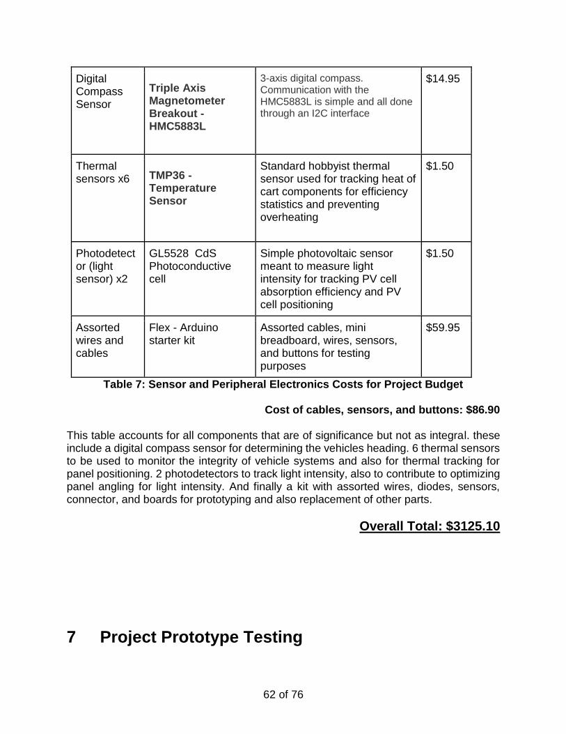
62 of 76
Digital Compass Sensor
Triple Axis Magnetometer Breakout - HMC5883L
3-axis digital compass. Communication with the HMC5883L is simple and all done through an I2C interface
$14.95
Thermal sensors x6 TMP36 -
Temperature Sensor
Standard hobbyist thermal sensor used for tracking heat of cart components for efficiency statistics and preventing overheating
$1.50
Photodetector (light sensor) x2
GL5528 CdS Photoconductive cell
Simple photovoltaic sensor meant to measure light intensity for tracking PV cell absorption efficiency and PV cell positioning
$1.50
Assorted wires and cables
Flex - Arduino starter kit
Assorted cables, mini breadboard, wires, sensors, and buttons for testing purposes
$59.95
Table 7: Sensor and Peripheral Electronics Costs for Project Budget
Cost of cables, sensors, and buttons: $86.90 This table accounts for all components that are of significance but not as integral. these include a digital compass sensor for determining the vehicles heading. 6 thermal sensors to be used to monitor the integrity of vehicle systems and also for thermal tracking for panel positioning. 2 photodetectors to track light intensity, also to contribute to optimizing panel angling for light intensity. And finally a kit with assorted wires, diodes, sensors, connector, and boards for prototyping and also replacement of other parts.
Overall Total: $3125.10
7 Project Prototype Testing
63 of 76
7.1 Hardware Test Environment
Since there is a variety of factors involved in the testing of our various parts as well as final prototype, we need to specify the environment and conditions our parts will be tested in. Some parts will need specific testing individually, including the cart, the batteries, and the solar panel. These tests will be evaluated independently of the prototype testing to calculate various specifications. For the design of the power optimization unit as well as the user interface, specific understanding of the cart specifications must be known along with the solar array performance and storage capabilities of the deep cycle batteries used. Various factors must be tested to ensure the reliability, safety, and proper functionality of the finished prototype.
7.1.1 Location Because of the size of our project, we will require a place to store and test the cart. The residence of one of our team members is optimal because of its proximity to the university. So after the cart acquisition, the storage and testing of the cart will take place at and around his house off of Carrigan Avenue just north of campus. here the cart can be safely kept and tested in the surrounding neighborhood. Because of the difficulty of transportation of the cart, we will likely not be moving the cart very much during the design, testing, and troubleshooting. We have access to a trailer for long distance transportation of the cart. One specific issue with our location is the Florida weather; while we will struggle with humidity and warm conditions, our cart will not experience cold weather conditions. The location chosen for our parts and prototype testing is more than acceptable, entirely practical for the accessibility to the university campus.
7.1.2 Ground Environment For the testing of the initial cart acquired and the later prototype, several different ground environments should be observed in their relationship to the performance of the test. With our location, we have a variety of different ground environments to test our carts with. Ground environment will help us evaluate the fluctuating power consumption of the motors based on the softness of the ground, as well as the various levels of steepness. For the energy optimization of our final project, the particular performance of the carts tires, motors, batteries, and optimizing unit must be evaluated. Less than ideal ground conditions can cause additional strain on the electrical components which can result in overheating and dangerous electrical fires. In the area north of the university campus, we have access to various terrains: road, off road, as well as various levels of steepness which will give us a strong sturdy design to design, test, and take performance data for.
7.1.3 Weather Conditions
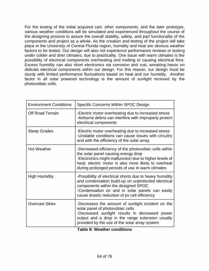
64 of 76
For the testing of the initial acquired cart, other components, and the later prototype, various weather conditions will be simulated and experienced throughout the course of the designing process to assure the overall stability, safety, and part functionality of the components and project as a whole. As the creation and testing of the project will take place in the University of Central Florida region, humidity and heat are obvious weather factors to be tested. Our design will also not experience performance reviews or testing under colder and drier climates, due to practicality. One issue with warm climates is the possibility of electrical components overheating and melting or causing electrical fires. Excess humidity can also short electronics via corrosion and rust, wreaking havoc on delicate electrical components within our design. For this reason, our design must be sturdy with limited performance fluctuations based on heat and our humidity. Another factor in all solar powered technology is the amount of sunlight received by the photovoltaic cells.
Environment Conditions Specific Concerns Within SPOC Design
Off Road Terrain -Electric motor overheating due to increased stress -Airborne debris can interfere with improperly protect electrical components
Steep Grades -Electric motor overheating due to increased stress -Unstable conditions can cause issues with circuitry and with the efficiency of the solar array.
Hot Weather -Decreased efficiency of the photovoltaic cells within the solar panel causing energy drop -Electronics might malfunction due to higher levels of heat; electric motor is also more likely to overheat during prolonged periods of use in warm climates
High Humidity -Possibility of electrical shorts due to heavy humidity and condensation build-up on unprotected electrical components within the designed SPOC -Condensation on and in solar panels can easily cause drastic reduction of pv cell efficiency
Overcast Skies -Decreases the amount of sunlight incident on the solar panel of photovoltaic cells -Decreased sunlight results in decreased power output and a drop in the range extension usually provided by the use of the solar array system
Table 8: Weather conditions
65 of 76
7.2 Hardware Specific Testing
With a number of different subsystems and components, the possibility for error is rather high with the individual parts and the interactions between them. To design and code our power optimization framework, the core of the project, we have to know the performance of our various components with a minimized amount of error. Under various weather and daytime conditions, the solar panel will perform at different levels of performance. For calculated energy efficiency, our team must test the solar panels. The electric cart will be tested before and after design modifications to accurately adjust and calculate the adjustments of the speed and range of the electric cart. Under various heat and speed conditions, the performance of the energy optimization is positively affected. We will be observing the performance of the lead-acid batteries in comparison with the purchased deep cycle Trojan batteries. Battery life and total charge time are likely to be affected by environment variables, so various tests will be conducted on the resilience and performance of the batteries. Finally, after the design of the prototype, our team will conduct a myriad of tests on the prototype. This testing will likely be followed by several rounds of troubleshooting and additional testing to optimize things such as range, speed, component temperatures,and user interfacing.
7.2.1 Solar Panel Testing The performance of the chosen solar panel will likely be affected a variety of different factors. The varying performance must be evaluated to design the rest of the systems and calculate the SPOC’s ability to reach the desired goal specifications. Atmospheric conditions are the main contributor to solar panel inefficiencies. Photovoltaic cells work best when the sunlight is orthogonally incident on the substrate of the panel. This rarely occurs in real world applications, so the effect of the angle of incidence on the panel efficiency is highly important to the design. [44]
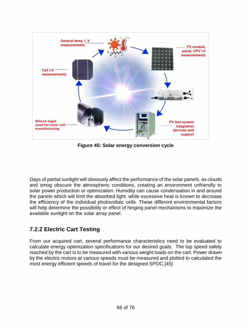
66 of 76
Figure 45: Solar energy conversion cycle
Days of partial sunlight will obviously affect the performance of the solar panels, as clouds and smog obscure the atmospheric conditions, creating an environment unfriendly to solar power production or optimization. Humidity can cause condensation in and around the panels which will limit the absorbed light, while excessive heat is known to decrease the efficiency of the individual photovoltaic cells. These different environmental factors will help determine the possibility or effect of hinging panel mechanisms to maximize the available sunlight on the solar array panel.
7.2.2 Electric Cart Testing From our acquired cart, several performance characteristics need to be evaluated to calculate energy optimization specifications for our desired goals. The top speed safely reached by the cart is to be measured with various weight loads on the cart. Power drawn by the electric motors at various speeds must be measured and plotted to calculated the most energy efficient speeds of travel for the designed SPOC.[45]
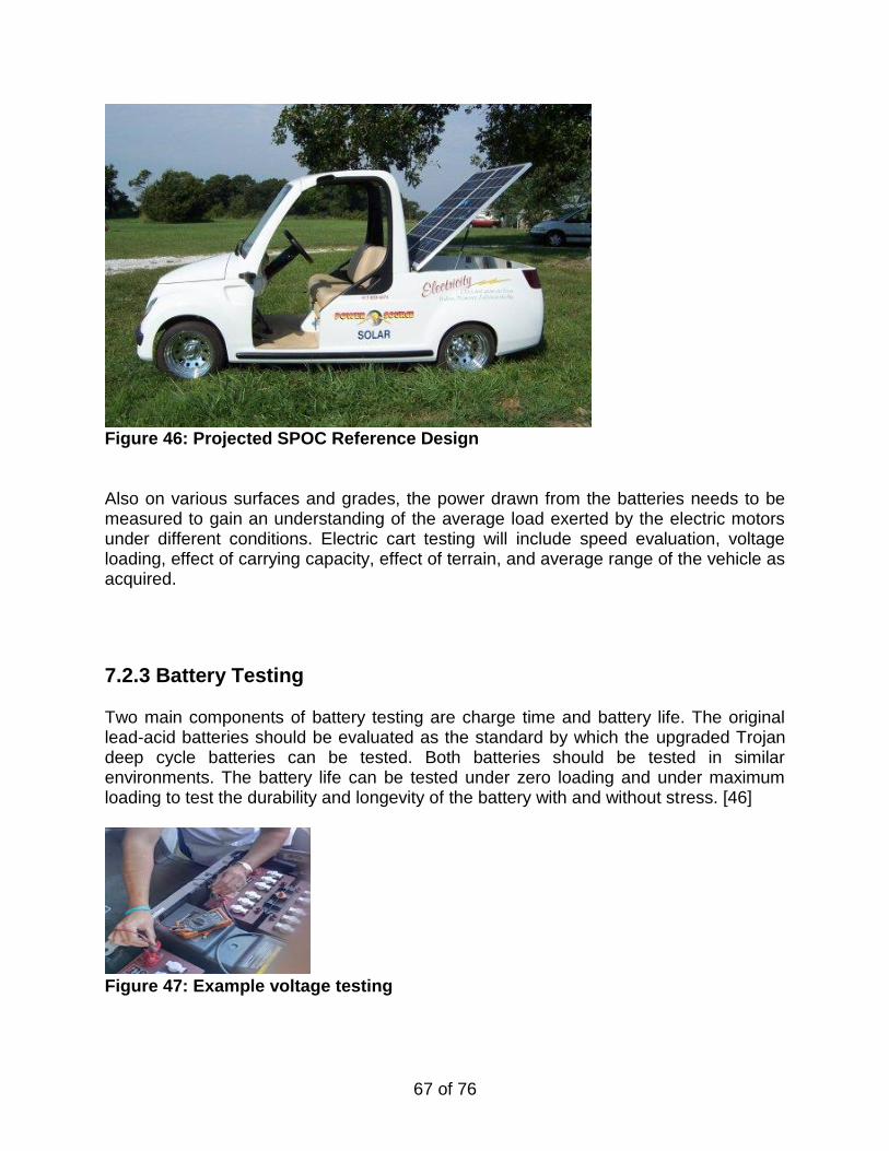
67 of 76
Figure 46: Projected SPOC Reference Design Also on various surfaces and grades, the power drawn from the batteries needs to be measured to gain an understanding of the average load exerted by the electric motors under different conditions. Electric cart testing will include speed evaluation, voltage loading, effect of carrying capacity, effect of terrain, and average range of the vehicle as acquired.
7.2.3 Battery Testing Two main components of battery testing are charge time and battery life. The original lead-acid batteries should be evaluated as the standard by which the upgraded Trojan deep cycle batteries can be tested. Both batteries should be tested in similar environments. The battery life can be tested under zero loading and under maximum loading to test the durability and longevity of the battery with and without stress. [46]
Figure 47: Example voltage testing
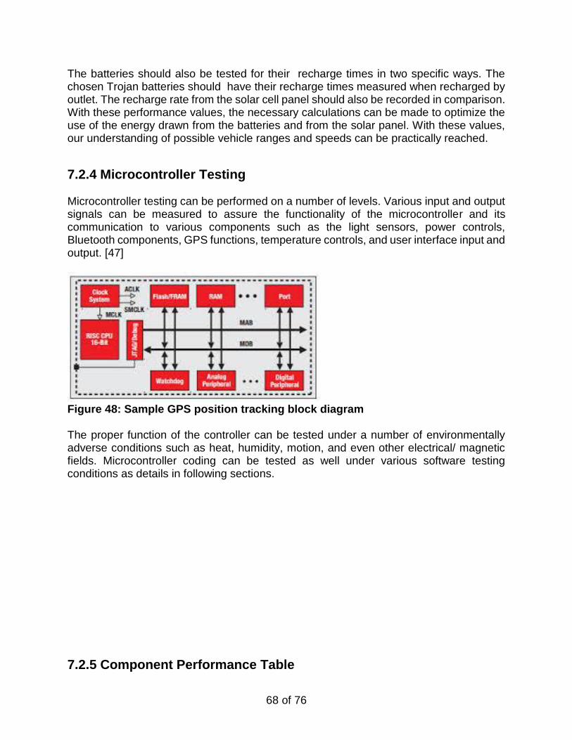
68 of 76
The batteries should also be tested for their recharge times in two specific ways. The chosen Trojan batteries should have their recharge times measured when recharged by outlet. The recharge rate from the solar cell panel should also be recorded in comparison. With these performance values, the necessary calculations can be made to optimize the use of the energy drawn from the batteries and from the solar panel. With these values, our understanding of possible vehicle ranges and speeds can be practically reached.
7.2.4 Microcontroller Testing Microcontroller testing can be performed on a number of levels. Various input and output signals can be measured to assure the functionality of the microcontroller and its communication to various components such as the light sensors, power controls, Bluetooth components, GPS functions, temperature controls, and user interface input and output. [47]
Figure 48: Sample GPS position tracking block diagram The proper function of the controller can be tested under a number of environmentally adverse conditions such as heat, humidity, motion, and even other electrical/ magnetic fields. Microcontroller coding can be tested as well under various software testing conditions as details in following sections.
7.2.5 Component Performance Table
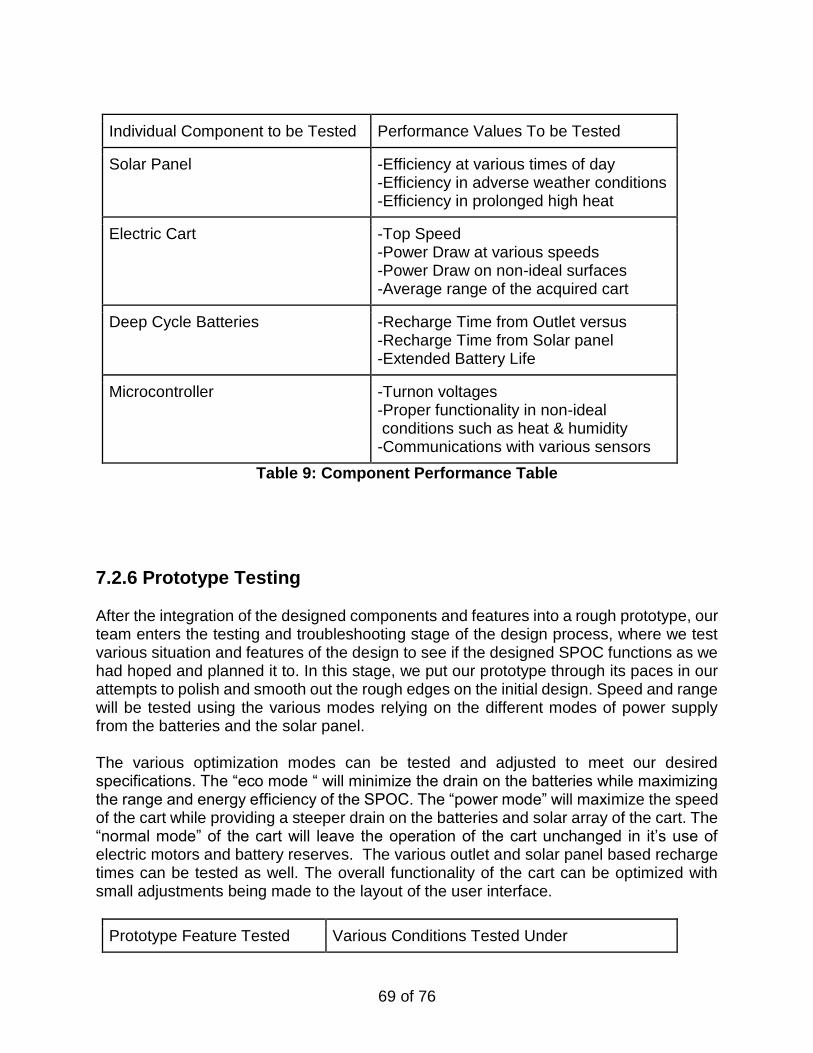
69 of 76
Individual Component to be Tested Performance Values To be Tested
Solar Panel -Efficiency at various times of day -Efficiency in adverse weather conditions -Efficiency in prolonged high heat
Electric Cart -Top Speed -Power Draw at various speeds -Power Draw on non-ideal surfaces -Average range of the acquired cart
Deep Cycle Batteries -Recharge Time from Outlet versus -Recharge Time from Solar panel -Extended Battery Life
Microcontroller -Turnon voltages -Proper functionality in non-ideal conditions such as heat & humidity -Communications with various sensors
Table 9: Component Performance Table
7.2.6 Prototype Testing After the integration of the designed components and features into a rough prototype, our team enters the testing and troubleshooting stage of the design process, where we test various situation and features of the design to see if the designed SPOC functions as we had hoped and planned it to. In this stage, we put our prototype through its paces in our attempts to polish and smooth out the rough edges on the initial design. Speed and range will be tested using the various modes relying on the different modes of power supply from the batteries and the solar panel. The various optimization modes can be tested and adjusted to meet our desired specifications. The “eco mode “ will minimize the drain on the batteries while maximizing the range and energy efficiency of the SPOC. The “power mode” will maximize the speed of the cart while providing a steeper drain on the batteries and solar array of the cart. The “normal mode” of the cart will leave the operation of the cart unchanged in it’s use of electric motors and battery reserves. The various outlet and solar panel based recharge times can be tested as well. The overall functionality of the cart can be optimized with small adjustments being made to the layout of the user interface.
Prototype Feature Tested Various Conditions Tested Under
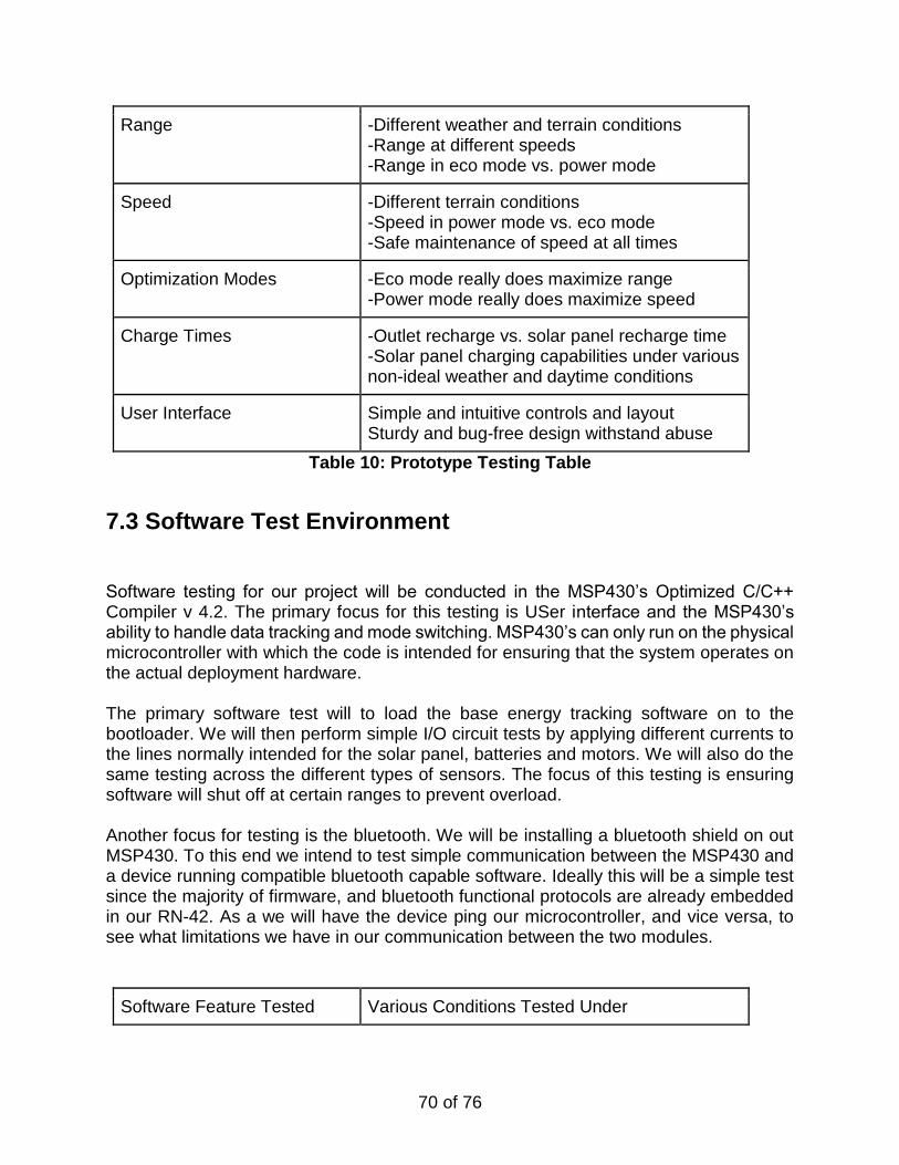
70 of 76
Range -Different weather and terrain conditions -Range at different speeds -Range in eco mode vs. power mode
Speed -Different terrain conditions -Speed in power mode vs. eco mode -Safe maintenance of speed at all times
Optimization Modes -Eco mode really does maximize range -Power mode really does maximize speed
Charge Times -Outlet recharge vs. solar panel recharge time -Solar panel charging capabilities under various non-ideal weather and daytime conditions
User Interface Simple and intuitive controls and layout Sturdy and bug-free design withstand abuse
Table 10: Prototype Testing Table
7.3 Software Test Environment
Software testing for our project will be conducted in the MSP430’s Optimized C/C++ Compiler v 4.2. The primary focus for this testing is USer interface and the MSP430’s ability to handle data tracking and mode switching. MSP430’s can only run on the physical microcontroller with which the code is intended for ensuring that the system operates on the actual deployment hardware. The primary software test will to load the base energy tracking software on to the bootloader. We will then perform simple I/O circuit tests by applying different currents to the lines normally intended for the solar panel, batteries and motors. We will also do the same testing across the different types of sensors. The focus of this testing is ensuring software will shut off at certain ranges to prevent overload. Another focus for testing is the bluetooth. We will be installing a bluetooth shield on out MSP430. To this end we intend to test simple communication between the MSP430 and a device running compatible bluetooth capable software. Ideally this will be a simple test since the majority of firmware, and bluetooth functional protocols are already embedded in our RN-42. As a we will have the device ping our microcontroller, and vice versa, to see what limitations we have in our communication between the two modules.
Software Feature Tested Various Conditions Tested Under
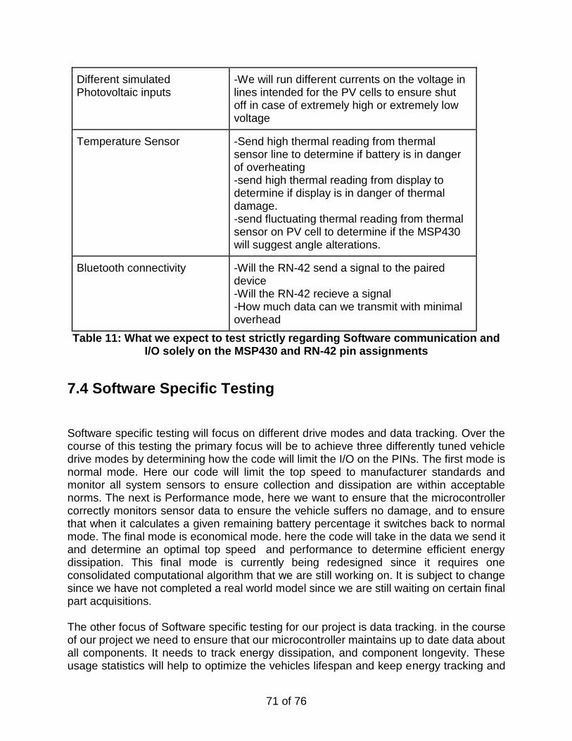
71 of 76
Different simulated Photovoltaic inputs
-We will run different currents on the voltage in lines intended for the PV cells to ensure shut off in case of extremely high or extremely low voltage
Temperature Sensor -Send high thermal reading from thermal sensor line to determine if battery is in danger of overheating -send high thermal reading from display to determine if display is in danger of thermal damage. -send fluctuating thermal reading from thermal sensor on PV cell to determine if the MSP430 will suggest angle alterations.
Bluetooth connectivity -Will the RN-42 send a signal to the paired device -Will the RN-42 recieve a signal -How much data can we transmit with minimal overhead
Table 11: What we expect to test strictly regarding Software communication and I/O solely on the MSP430 and RN-42 pin assignments
7.4 Software Specific Testing
Software specific testing will focus on different drive modes and data tracking. Over the course of this testing the primary focus will be to achieve three differently tuned vehicle drive modes by determining how the code will limit the I/O on the PINs. The first mode is normal mode. Here our code will limit the top speed to manufacturer standards and monitor all system sensors to ensure collection and dissipation are within acceptable norms. The next is Performance mode, here we want to ensure that the microcontroller correctly monitors sensor data to ensure the vehicle suffers no damage, and to ensure that when it calculates a given remaining battery percentage it switches back to normal mode. The final mode is economical mode. here the code will take in the data we send it and determine an optimal top speed and performance to determine efficient energy dissipation. This final mode is currently being redesigned since it requires one consolidated computational algorithm that we are still working on. It is subject to change since we have not completed a real world model since we are still waiting on certain final part acquisitions. The other focus of Software specific testing for our project is data tracking. in the course of our project we need to ensure that our microcontroller maintains up to date data about all components. It needs to track energy dissipation, and component longevity. These usage statistics will help to optimize the vehicles lifespan and keep energy tracking and
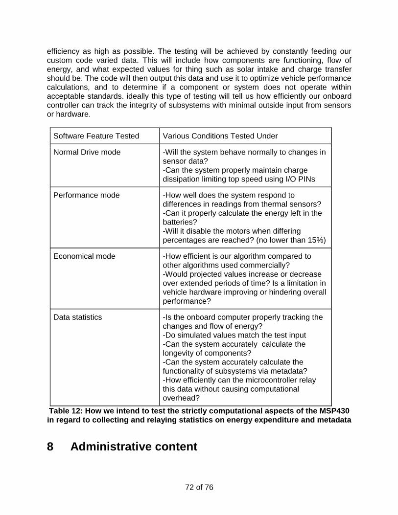
72 of 76
efficiency as high as possible. The testing will be achieved by constantly feeding our custom code varied data. This will include how components are functioning, flow of energy, and what expected values for thing such as solar intake and charge transfer should be. The code will then output this data and use it to optimize vehicle performance calculations, and to determine if a component or system does not operate within acceptable standards. ideally this type of testing will tell us how efficiently our onboard controller can track the integrity of subsystems with minimal outside input from sensors or hardware.
Software Feature Tested Various Conditions Tested Under
Normal Drive mode -Will the system behave normally to changes in sensor data? -Can the system properly maintain charge dissipation limiting top speed using I/O PINs
Performance mode -How well does the system respond to differences in readings from thermal sensors? -Can it properly calculate the energy left in the batteries? -Will it disable the motors when differing percentages are reached? (no lower than 15%)
Economical mode -How efficient is our algorithm compared to other algorithms used commercially? -Would projected values increase or decrease over extended periods of time? Is a limitation in vehicle hardware improving or hindering overall performance?
Data statistics -Is the onboard computer properly tracking the changes and flow of energy? -Do simulated values match the test input -Can the system accurately calculate the longevity of components? -Can the system accurately calculate the functionality of subsystems via metadata? -How efficiently can the microcontroller relay this data without causing computational overhead?
Table 12: How we intend to test the strictly computational aspects of the MSP430 in regard to collecting and relaying statistics on energy expenditure and metadata
8 Administrative content
73 of 76
8.1 Milestones
The project will be organized according to a series of milestones. These milestones will help serve as the timeline used to gauge the overall progress of the project. Each milestone, or phase, symbolizes transition from one specific state of functional completion to another. The phases are arranged so that we can start with the most basic design goals and work up through more complex design states to reach the final state of the project, as well as allowing for additional improvements as we finish each state.
8.1.0 Phase 0: Cart For tracking purposes, Phase 0 is included as the starting point of the design portion of the project. This Phase is marked by the acquisition of the golf cart, and is the most basic functional stage of the design implementation. At completion of this phase, the cart will be functional, though entirely dependent on periodic recharging. This phase represents the completion of the initial phases of design and acquisition, though it requires very little in the way of implementation time and effort. It also requires the largest degree of funding.
8.1.1 Phase 1: Energy Acquisition speed for the solar array will strongly affect the time required for completion of Phase 1. At completion of this phase, the solar array will be linked to the battery for passive charging, much like a portable version of the standalone power stations already in place in some areas for use by electric vehicles. This portable solar charging apparatus will likely be connected through the charging circuit already present in the golf cart, easily modified for variable solar power input instead of steady cycle mains power. This stage of project implementation completion will mark the initial transition away from a dependence on externally supplied mains power to internally supplied solar power for the purposes of charging the vehicle’s battery pack, thus satisfying a primary project goal of sustainability. However, at this point the project is still mostly dependent on an external power source, as the solar energy will only be utilized while the cart is in an idle or inactive state. Additionally, the cart at this point does not have in place any means of energy management or other associated functions.
8.1.2 Phase 2: Control After the solar panel has been integrated to charge the cart at rest, there is still a great deal of room for improvement. These optimizations will be implemented through an onboard microcontroller. This control device will collect a great deal of information on the
74 of 76
many different systems and sensors present in the cart. This data will then be used to increase the overall efficiency of the system. At this point, the system will be locked into a specific mode of high efficiency use, which will effectively maximize the range of the cart. The next phase of project completion will add an additional layer of functionality to this element of control by allowing for user input. Maximization of efficiency will only be possible through a great deal of testing, as well as highly effective programming through the microcontroller. Because of this dependency on testing, it is vital that the solar panels be tested during this stage of implementation in parallel with the integration of the microcontroller. This will allow us to begin the programming of the microcontroller as soon as it has been integrated into the overall system.
8.1.3 Phase 3: User In accordance with the design goals of this project, the previous phase’s maximum power-optimization mode will not be the only option available to users of the cart. In order to facilitate the changing of operational modes, a User Interface will be implemented. This user interface will utilize a monitor in tandem with a series of buttons to present the information gathered by the control device implemented in Phase 2. This information, such as range, current power output, battery charge, etc., will also help the user decide which of several running modes to choose from. These modes will each favor to some extent either performance or efficiency, furthering the goal of power optimization and increasing market feasibility.
8.1.4 Phase 4: Possible Project Component Extensions During the project, we will undoubtedly arrive upon more ideas for potential implementation and improvement options. These ideas will be recorded as they are created, so that they may be implemented if time and funding allow in this final stage of the project. There are many potential ideas available for implementation within the scope of this project, but time and money are both limited on this project. As a result, ideas must be judiciously chosen based on careful analysis before integration into the final project. While creating this initial design document, we have already found several options for further project extension that do not properly align with the initial design scope for our project, as well as some options that may prove unfeasible because of time or other constraints. These options are further explored in various sections above.
8.1.5 Phase 5: Testing & Troubleshooting As the project reaches its final stages, we will be testing and recording the performance of our design to maximize its power, range, and efficiency. Some of this testing will require brute force trial and error testing to perfect the implemented design. Range, speed, and
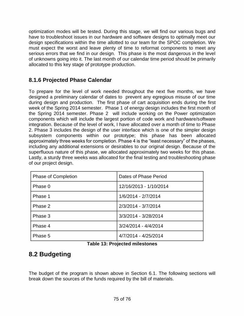
75 of 76
optimization modes will be tested. During this stage, we will find our various bugs and have to troubleshoot issues in our hardware and software designs to optimally meet our design specifications within the time allotted to our team for the SPOC completion. We must expect the worst and leave plenty of time to reformat components to meet any serious errors that we find in our design. This phase is the most dangerous in the level of unknowns going into it. The last month of our calendar time period should be primarily allocated to this key stage of prototype production.
8.1.6 Projected Phase Calendar To prepare for the level of work needed throughout the next five months, we have designed a preliminary calendar of dates to prevent any egregious misuse of our time during design and production. The first phase of cart acquisition ends during the first week of the Spring 2014 semester. Phase 1 of energy design includes the first month of the Spring 2014 semester. Phase 2 will include working on the Power optimization components which will include the largest portion of code work and hardware/software integration. Because of the level of work, I have allocated over a month of time to Phase 2. Phase 3 includes the design of the user interface which is one of the simpler design subsystem components within our prototype; this phase has been allocated approximately three weeks for completion. Phase 4 is the “least necessary” of the phases, including any additional extensions or desirables to our original design. Because of the superfluous nature of this phase, we allocated approximately two weeks for this phase. Lastly, a sturdy three weeks was allocated for the final testing and troubleshooting phase of our project design.
Phase of Completion Dates of Phase Period
Phase 0 12/16/2013 - 1/10/2014
Phase 1 1/6/2014 - 2/7/2014
Phase 2 2/3/2014 - 3/7/2014
Phase 3 3/3/2014 - 3/28/2014
Phase 4 3/24/2014 - 4/4/2014
Phase 5 4/7/2014 - 4/25/2014
Table 13: Projected milestones
8.2 Budgeting
The budget of the program is shown above in Section 6.1. The following sections will break down the sources of the funds required by the bill of materials.
76 of 76
8.2.1 Outside Funding All of the planned expenses will be covered by Duke Energy. These expenses are shown above, in Section 6.1, and total to $2,674.79. Within this funding, there is a small amount of flexibility depending on price fluctuation for each part or subsystem.
8.2.3 Personal Thanks to Duke
We would like to thank duke energy for their sizable contribution of $2,674.79 to our project. This money was fundamental in helping us acquire the best parts, to make the most energy efficient machine possible. Though this is just a foreshadowing of things to come we believe that the SPOC speaks to Duke Energy’s philosophy of energy conservation. Our product is a step up from conventional fossil fuel vehicles achieving similar speeds and range in suburban settings, with zero emissions. Further more that fact that it is solar powered means that it puts no stress on a city's power grid, and can even serve as an auxiliary power source for a users energy needs. It is our hope that the SPOC will bring about a paradigm shift in urban human transit. By presenting cities with an easy to maintain, reliable, and conventional electric people carrier we can change the way people travel in their day to day commute. However, our product is not simply limited to personal transport vehicles. We believe that with the proper technology and opportunity our project could be scaled to accommodate more passengers making for public transit that can run reliably, with minimal maintenance or cost. Additionally our novel energy tracking software and hardware could bring about improvements in how electrical systems interact when using high power or requiring frequent charging.
By working with the largest Energy company in the United States we believe we have a real chance to improve people’s lives by changing how they commute. And it is our hope that our work will also contribute to Duke Energy’s legacy of providing sustainable, affordable, reliable, clean energy.
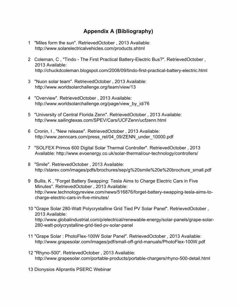
Appendix A (Bibliography) 1 "Miles form the sun". RetrievedOctober , 2013 Available:
http://www.solarelectricalvehicles.com/products.shtml 2 Coleman, C , "Tindo The First Practical BatteryElectric Bus?". RetrievedOctober ,
2013 Available: http://chuckdcoleman.blogspot.com/2008/09/tindofirstpracticalbatteryelectric.html
3 "Nuon solar team". RetrievedOctober , 2013 Available:
http://www.worldsolarchallenge.org/team/view/13 4 "Overview". RetrievedOctober , 2013 Available:
http://www.worldsolarchallenge.org/page/view_by_id/76 5 "University of Central Florida Zenn". RetrievedOctober , 2013 Available:
http://www.sailingtexas.com/SPEV/Cars/UCFZenn/ucfzenn.html 6 Cronin, I , "New release". RetrievedOctober , 2013 Available:
http://www.zenncars.com/press_rel/04_09/ZENN_under_10000.pdf 7 "SOLFEX Primos 600 Digital Solar Thermal Controller". RetrievedOctober , 2013
Available: http://www.evoenergy.co.uk/solarthermal/ourtechnology/controllers/ 8 "Smile". RetrievedOctober , 2013 Available:
http://starev.com/images/pdfs/brochures/sep/g%20smile%20e%20brochure_small.pdf 9 Bullis, K , "Forget Battery Swapping: Tesla Aims to Charge Electric Cars in Five
Minutes". RetrievedOctober , 2013 Available: http://www.technologyreview.com/news/516876/forgetbatteryswappingteslaaimstochargeelectriccarsinfiveminutes/
10 "Grape Solar 280Watt Polycrystalline Grid Tied PV Solar Panel". RetrievedOctober ,
2013 Available: http://www.globalindustrial.com/p/electrical/renewableenergy/solarpanels/grapesolar280wattpolycrystallinegridtiedpvsolarpanel
11 "Grape Solar : PhotoFlex100W Solar Panel". RetrievedOctober , 2013 Available:
http://www.grapesolar.com/images/pdf/smalloffgridmanuals/PhotoFlex100W.pdf 12 "Rhyno500". RetrievedOctober , 2013 Available:
http://www.grapesolar.com/portableproducts/portablechargers/rhyno500detail.html 13 Dionysios Aliprantis PSERC Webinar
14 Pesaran, A , "Sustainability: The future of transportation". RetrievedOctober , 2013 Available: http://www.nrel.gov/vehiclesandfuels/energystorage/pdfs/42469.pdf
15 Evanczuk, S , "Designing a HighEfficiency Solar Power Battery Charger".
RetrievedOctober , 2013 Available: http://www.digikey.com/us/en/techzone/energyharvesting/resources/articles/designingasolarpowerbatterycharger.html
16 "Products". RetrievedNovember , 2013 Available: http://arduino.cc/en/Main/Products 17 "Arduino BT". RetrievedNovember , 2013 Available:
http://arduino.cc/en/Main/ArduinoBoardBT?from=Main.ArduinoBoardBluetooth 18 "MSP430™ + CC2560 Bluetooth® Platform". RetrievedNovember , 2013 Available:
http://www.ti.com/lit/ml/swpt038/swpt038.pdf 19 "MSP430™ UltraLowPower Microcontrollers". RetrievedNovember , 2013 Available:
http://www.ti.com/lit/sg/slab034w/slab034w.pdf 20 "Adding Bluetooth to your MSP430 Project". RetrievedNovember , 2013 Available:
http://www.msp430launchpad.com/2011/08/addingbluetoothtoyourmsp430project.html
21 "Premium Flooded Batteries... optimized for Renewable Energy". RetrievedNovember ,
2013 Available: http://www.trojanbatteryre.com/products/products.html 22 Evanczuk, S , "Designing a HighEfficiency Solar Power Battery Charger".
RetrievedOctober , 2013 Available: http://www.digikey.com/us/en/techzone/energyharvesting/resources/articles/designingasolarpowerbatterycharger.html
23 "EEL 4914C: Electrical Engineering Design MSP430 Demo/Assignment ".
RetrievedNovember , 2013 Available: http://www.add.ece.ufl.edu/4924/docs/MSP430F2013_assn.pdf
24 "HIGHVOLTAGE ADJUSTABLE REGULATOR". RetrievedNovember , 2013
Available: http://www.ti.com/lit/ds/symlink/tl783.pdf 25 " RN42/RN42N Data Sheet". RetrievedDecember , 2013 Available:
https://www.sparkfun.com/datasheets/Wireless/Bluetooth/rn42ds.pdf 26 "Adding Bluetooth to your MSP430 Project". RetrievedNovember , 2013 Available:
http://www.msp430launchpad.com/2011/08/addingbluetoothtoyourmsp430project.html
27 "CdS Photocell Photoconductive Cell GL5528". RetrievedDecember , 2013 Available: https://www.bananarobotics.com/shop/CdSPhotocellGL5528(5%20pack)
28 "TMP36 Temperature Sensor". RetrievedDecember , 2013 Available:
https://www.sparkfun.com/products/10988 29 "Triple Axis Magnetometer Breakout HMC5883L". RetrievedDecember , 2013
Available: https://www.sparkfun.com/products/10530 30 “Star EV ‘Smile’ Car” Retrieved November 2013. Available http://
starev.com/images/pdfs/brochures/ 31”Classic Club Car Design” Retrieved november 2013. Available from :
http://www.clubcar.com/commercialbusiness/transport/pages/villager4.aspx 32 “Polaris GEM Cart” Retrieved October 2013. Avaialble from:
www.polaris.com/ENUS/GEMELECTRICCAR/Pages/Home.aspx 33 “Custom Cart Design’ by SC Carts” Retrieved October 2013. Available from:
http://sccarts.wordpress.com/2013/09/24/sccartscustomsolarcharginggolfcartpart1/
34w “Ford Focus Electric user interface” Retrieved November 2013. Available from
http://www.zemotoring.com/news/2011/01/fordfocuselectricuserinterfacemyfordtouch/
35 ‘Trina Solar Panel Specs and Picture” Retrieved December 2013. Available from
http://www.solarhome.org/trinasolartsm240pa05240wattssolarpanelmc4.aspx 36 “Specs and Pic for Power Film Flexible Solar Panel” Retrieved November 2013.
Available from: http://www.powerfilmsolar.com/products/oemcomparisonchart/ 37 ‘Specs and Pic for Grape Solar 390 W panel.” Retrieved November 2013. Available
from: http://www.grapesolar.com/250wmonogss250fab5.html 38 “Solar panel electrical wiring and network” Retrieved November 2013. Available from
:http://www.grapesolar.com/250wmonogss250fab5.html 39 ‘Solar Panel Architecture”Retrieved November 2013. Available from:
www.solarpanelmanufacturer.com 40 “Golf Cart Electrical Schematic’ retrieved October 2013. Available from:
http://binatani.com/ezgogolfcartwiringdiagramelectricsystem/
41 “Power Subsystem Diagrams” Retrieved November 2013. Available from:
http://hpevs.com/Site/ 42 “Trojan Battery Array” retrieved November 2013. Available from: http://fosterscramalotinn.com/ci_interior.html
43 “Microcontroller Integration” Retrieved November 2013. Available from: http://www.eit.unikl.de/koenig/gemeinsame_seiten/projects/ROSIG.html 44 “Solar Panel Testing Diagram” Retrieved November 2013. Available from: http://www.testfei.com/solarphotovoltaiccelltestequipment.html 45 “Electric Cart Testing” Retrieved December 2013. Avaiable from: http://visforvoltage.org/forum/solarvehicles/1835 46 “Battery Testing Diagram’ Retrieved December 2013. Available from: www. sandiegocart.com/ 47 “Microcontroller Testing Diagram” Retrieved December 2013. Available from: www. electronicsweekly.com 50 “Solar Charge System Simple Design’ Retrieved December 2013. Available from:
http://homemadecircuitsandschematics.blogspot.com/2011/12/howtobuildsolarpanelvoltage.html
51 “Blue Character OLED 16x2” Retrieved December 2013. Available from:
http://www.adafruit.com/products/823 52 “Tactile Switch Buttons (6mm tall) x10 pack” Retrieved December 2013. Available from:
http://www.adafruit.com/products/1490


