21
JIANGYIN TITANERGY CO.,LTD SOLAR ROOF MOUNTING SYSTEM INSTALLATION MANUAL Model Name : TT-ADJUSTABLE TILT LEGS

JIANGYIN TITANERGY CO.,LTD
SOLAR ROOF MOUNTING SYSTEM
INSTALLATION MANUAL
Model Name:TT-ADJUSTABLE TILT LEGS
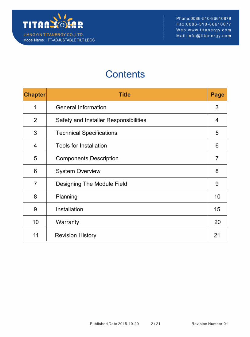
Contents
JIANGYIN TITANERGY CO.,LTD.
Phone:0086-510-86610879
Fax :0086-510-86610877
Web :www. t i t ane rgy. com
Ma i l : i n fo@t i tanergy.com
1 3
2 4
3
4
5
6
7
8
9
10
11
Chapter Page
General Information
Safety and Installer Responsibilities
Technical Specifications
Tools for Installation
Components Description
System Overview
Designing The Module Field
Planning
Installation
Warranty
Revision History
Title
Published Date 2015-10-20 2 / 21
5
6
7
8
9
10
15
20
21
Model Name:TT-ADJUSTABLE TILT LEGS
Revision Number:01

1. General information
Thank you for choosing the Titan solar roof mounting system. Made from custom- built aluminum extrusions
and components, Titan Solar's innovated design and improved frame strength greatly simplify solar panel
installation. The easy installation four steps make the D-Modules can be put into the D Rail on any position quickly. So, the D-Modules is pre-assembly with the clamp to save your install time.
Tilt-in Align Up Fasten
Easy installation four steps
Titan solar's versatile design makes it suitable for a wide variety of building types and zones including residential, commercial and remote environments.
Titansolar is backed by a 10-year warranty .(Fire Rated:C)
Published Date 2015-10-20 3 / 21
JIANGYIN TITANERGY CO.,LTD.
Phone:0086-510-86610879
Fax :0086-510-86610877
Web :www. t i t ane rgy. com
Ma i l : i n fo@t i tanergy.comModel Name:TT-ADJUSTABLE TILT LEGS
Revision Number:01

2. Safety and Installer Responsibilities
2.1 Handling and Installing Titan solar
It is critically important that safety practices are observed when installing
※ Do not throw or roughly handle any Titan solar components.
※ Do not bring Titan solar system into contact with sharp or heavy objects.
※ Do not modify Titan solar components in any way. The exchange of bolts, drilling of holes, bending or any other physical changes not described in
standard installation procedure will void the warranty.
※ It is the installer s responsibility to verify the integrity of the structure to '
which Titan solar components is fixed. Roofs or structures with
rotten/rusted bearers, undersized bearers, excessively spaced bearers, or any other unsuitable substructure cannot be used with Titan solar
components, and installation on such structures will void the warranty,and could result in death or serious injury.
2.2 Wind and Climate Design
Determining the wind pressures applies to your Titan solar system install
site, taking into account roof shape and geographic location. Sufficient
guidance is given in this document, but you may wish to procure a copy
of these standards.
※ REMEMBER average wind speeds are higher for structures mounted
closer to the roof perimeter zone (edge). Refer to Fixing within Roof '
Installation Zone for more information)'
※ Make sure your installation complies with local and national building
codes. Take into account relevant design parameters (wind speed, exposure and topographic factor) when determining the loading for the
installation.
※ If alternative fasteners are used to fix the framing to the roof (assuming
supplied fasteners are unsuitable for any reason), all screw fasteners
must be of equal or greater strength to those supplied with your
Titan solar system order.
Caution
Installation of this product is to be
performed only by professionally trained installers. Any attempt by an unqualified person to install this
product could result in death or serious injury.
Published Date 2015-10-20 4 / 21
JIANGYIN TITANERGY CO.,LTD.
Phone:0086-510-86610879
Fax :0086-510-86610877
Web :www. t i t ane rgy. com
Ma i l : i n fo@t i tanergy.comModel Name:TT-ADJUSTABLE TILT LEGS
Revision Number:01
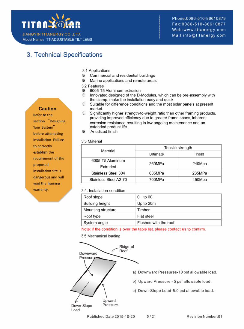
3. Technical Specifications
3.1 Applications ※ Commercial and residential buildings
※ Marine applications and remote areas
3.2 Features ※ 6005-T5 Aluminum extrusion
※ Innovated designed of the D-Modules, which can be pre-assembly with the clamp, make the installation easy and quick.
※ Suitable for difference conditions and the most solar panels at present market.
※ Significantly higher strength-to-weight ratio than other framing products, providing improved efficiency due to greater frame spans, inherent
corrosion resistance resulting in low ongoing maintenance and an extended product life.
※ Anodized finish
3.3 Material
Material Tensile strength
Ultimate Yield
6005-T5 Aluminum
Extruded 260MPa 240Mpa
Stainless Steel 304 635MPa 235MPa
Stainless Steel A2 -70 700MPa 450Mpa
3.4. Installation condition
Roof slope 0°to 60°
Building height Up to 20m
Mounting structure Timber
Roof type Flat steel
System angle Flushed with the roof
Note: if the condition is over the table list, please contact us to confirm.
Caution
Refer to the section “Designing
Your System”
before attempting installation. Failure to correctly
establish the
requirement of the proposed installation site is
dangerous and will
void the framing
warranty.
Published Date 2015-10-20 5 / 21
JIANGYIN TITANERGY CO.,LTD.
Phone:0086-510-86610879
Fax :0086-510-86610877
Web :www. t i t ane rgy. com
Ma i l : i n fo@t i tanergy.comModel Name:TT-ADJUSTABLE TILT LEGS
Revision Number:01
Down-SlopeLoad
UpwardPressure
DownwardPressure
3.5 Mechanical loading
Ridge ofRoof
a) Downward Pressures-10 psf allowable load.
b) Upward Pressure - 5 psf allowable load.
c) Down-Slope Load-5.0 psf allowable load.

4. Tools for Installation
The following tools are required for the installation:
※ 6 mm Allen key or hexagonal driver bit.
If using a 6mm driver bit, make sure the cordless
power tool used for the driving has a hand-tight clutch setting a fine (soft impact drive to prevent )
damage to the fragile glass panels and threads on the Structure.
※ Cordless drill; Drill or impact driver for driving roof material fixings
※ Angle grinder; For terracotta tile roof installation, and angle grinder
fitted with a continuous edge diamond tipped
tile0cutting blade; gloves, hearing protection, a face protection mask, and a suitably rated breathing protection mask for all people in proximity of grinding
※ Gloves; Protect the hazard of the sharp corners.
※ Cord or color pen; Mark the installation position;
※ Spirit level
※ Rule
Published Date 2015-10-20 6 / 21
JIANGYIN TITANERGY CO.,LTD.
Phone:0086-510-86610879
Fax :0086-510-86610877
Web :www. t i t ane rgy. com
Ma i l : i n fo@t i tanergy.comModel Name:TT-ADJUSTABLE TILT LEGS
Revision Number:01

5. Components Description
Published Date 2015-10-20 7 / 21
JIANGYIN TITANERGY CO.,LTD.
Phone:0086-510-86610879
Fax :0086-510-86610877
Web :www. t i t ane rgy. com
Ma i l : i n fo@t i tanergy.com
T -T Rail ※ hold each panel row ※ length can be customized
※ 6005-T5 extruded aluminum
Standard Rail Length
808~826mm wide panels
990~1020mm wide panels
2560mm (3 panels)
3405mm (4 panels)
4200mm (4 panels)
TT Rail Splice
Kit
※ Extend TT Rail to any length as required by the
quantity or width of the solar panels
Inter Clamp Kit for Framed Modules
※ Fit between two panels
Front Leg
Rear Leg
Bolts& Nuts
※ Fastened with a 6mm Allen key
※ Standard pre-assembly for
the usual
panels with
thickness 30, 35, 40, 46, 50, 57mm
End Clamp Kit for Framed Modules
※ Hold the edge of each end
panels
※ Fastened with a 6mm Allen key
※ Standard pre-assembly for the usual panels with thickness 30, 35, 40, 46, 50, 57mm
Fit on the roof
Include 2pcs st6.3*80 wood screws ※ ※
Fit on the roofInclude 2pcs st6.3*80 wood screwsInclude 1pc M8*25 bolt,1pc M8 spring washer,2pcs M8,OD18 lock washers,1pc nut,1pc M8*55 bolt,4pcs flange nuts with M8 locking teeth,1pc M8*20 bolt,1pc M8*15 bolt
※ ※
Model Name:TT-ADJUSTABLE TILT LEGS
Revision Number:01
※ Include 2pcs M8*20 bolts,2pcs M8 spring washers,2pcs M8,OD18 lock washers
※ Include 1pc M8 bolt,1pc M8 spring washer,1pc nut
※ Include 1pc M8*25 bolt,1pc M8 spring washer,1pc nut
Include 1pc M8*25 bolt,1pc M8 spring washer,
2pcs M8,OD18 lock washers,1pc nut,1pc M8*55 bolt,
1pc flange nut with M8 locking teeth
※
※
Include 1pc M8*25 bolt,1pc M8 spring washer,
1pc M8,OD18 lock washer,1pc nut※
※※The installation direction of panels can be customized.(horizontal or vertical)
The length of TT-Rail can be customized.(1.05m~15.90m)

Published Date 2015-10-20 8 / 21
JIANGYIN TITANERGY CO.,LTD.
Phone:0086-510-86610879
Fax :0086-510-86610877
Web :www. t i t ane rgy. com
Ma i l : i n fo@t i tanergy.com
Variety of Screws
Wood Screw
Socket Head Screw
Grounding Lug
Fix the wire ※ Material:Cu ※ Include 1pc M8*25 bolt,1pc M8 spring washer,1pc M8, OD18 lock washer,1pc nut,1pcM6*15 bolt
※
Grounding Clip
Electric Conduction
※ Material:Stainless steel
※
Rubber Pad
Wearing pads
※ Change in time
※
6. System overview
① TT Rail ② TT Rail Splice (Optional)
③ Inter Clamp ④ End Clamp
⑤ Front Leg
①
③
④ ⑤ ⑥
⑥ Rear Leg
Model Name:TT-ADJUSTABLE TILT LEGS
Revision Number:01
With pad
※

7. Designing the module field
Below, the distances between roof connections for a portrait installation are specified. Clamp- on roof hooks
need to be installed in specific distances, depending on the distance of rafters and the stoical conditions.
1 Height of the module field: module height x number of modules vertically
2 Width of the module field: number of modules horizontally x (width of the module + 18 mm)+32 mm
3 Distance between roof connections vertically (according to the clamping points pre-defined by the module producer): Quarter-points of the modules, about 1/2 of module height.
4 Distance between roof connections horizontally: Depending on the distance between rafters and on the
static requirements (please see the Chapter 8 on page 11). 5 Distance between modules: 17 mm
When positioning the modules, please take into consideration
※ That the values above are
※ That dimensions of tiles or other roof covering and the position of the rafters define the precise actual horizontal distance between roof connections
※ That the distance between roof laths defines the precise actual vertical distance between roof
connections.
Published Date 2015-10-20 9 / 21
JIANGYIN TITANERGY CO.,LTD.
Phone:0086-510-86610879
Fax :0086-510-86610877
Web :www. t i t ane rgy. com
Ma i l : i n fo@t i tanergy.comModel Name:TT-ADJUSTABLE TILT LEGS
Revision Number:01

8. Planning
8.1 Determine the wind region of your installation site
Published Date 2015-10-20 10/ 21
JIANGYIN TITANERGY CO.,LTD.
Phone:0086-510-86610879
Fax :0086-510-86610877
Web :www. t i t ane rgy. com
Ma i l : i n fo@t i tanergy.com
Region
Region B
Region C
Region D
A
This document provides sufficient information for Titan solar system installation height less than 20 meters. If your installation site is more than 20 meters in height, please contact Titan solar to obtain
engineering data to support your installation.
8.3 Determine Roof Installation Roof Areas
Titan solar system can be installed anywhere on a roof but fixing centers are required to be reduced at
ridges and edges. The diagram below shows the area of higher wind loadings within 0.2A and 0.2Bof a
roof edge ridge (where A and B are the planned dimension of the building).
8.2. Determine the height of the of your installation site
Center Zone
Edge Zone
The following table will help you determine the maximum rail support spacing for your project. Also note that if the roof slope is less than 10 degree the reduction on spacing does not apply.
A≤
45msec< B≤ 57msec
57msec< C≤ 66msec
66msec< D≤ 80msec
45msec
Model Name:TT-ADJUSTABLE TILT LEGS
Revision Number:01
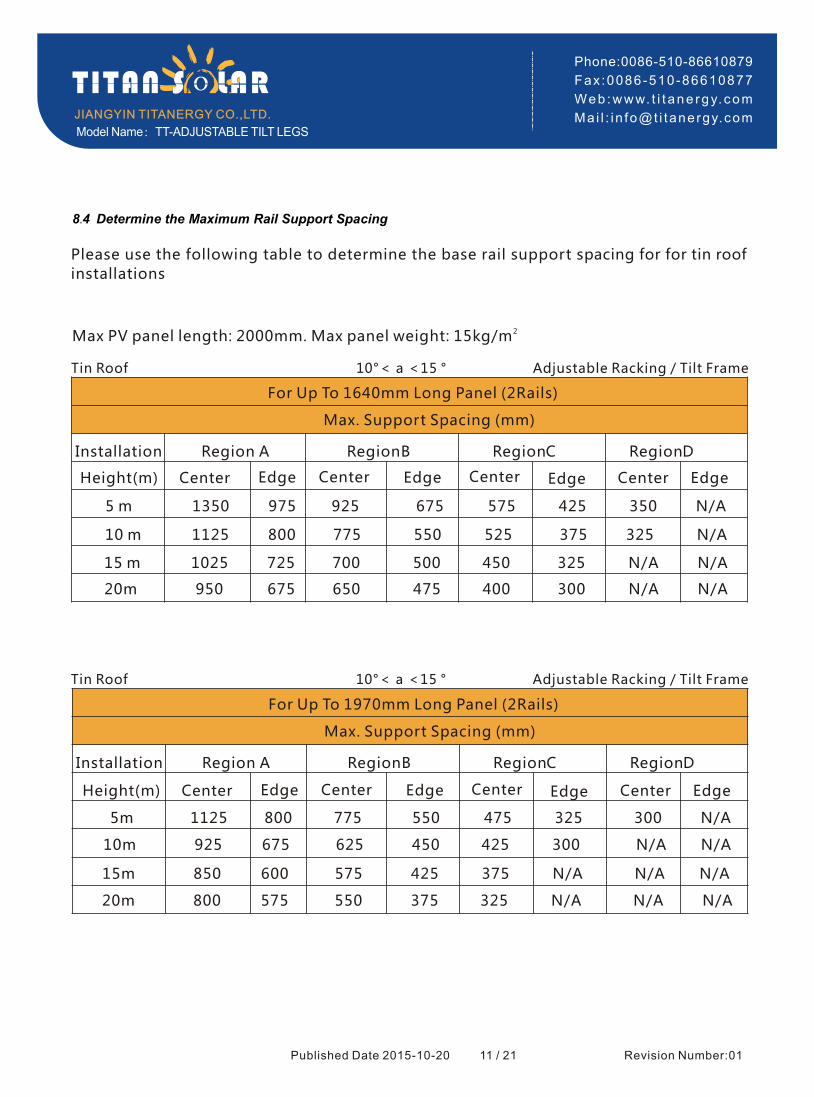
8.4 Determine the Maximum Rail Support Spacing
Published Date 2015-10-20 11 / 21
JIANGYIN TITANERGY CO.,LTD.
Phone:0086-510-86610879
Fax :0086-510-86610877
Web :www. t i t ane rgy. com
Ma i l : i n fo@t i tanergy.com
For Up To 1970mm Long Panel (2Rails)
Max. Support Spacing (mm)
Installation Region A RegionB RegionC RegionD
Height(m) Center Center Center Edge Center EdgeEdgeEdge
For Up To 1640mm Long Panel (2Rails)
Max. Support Spacing (mm)
Installation Region A RegionB RegionC RegionD
Please use the following table to determine the base rail support spacing for for tin roof
installations
2Max PV panel length: 2000mm. Max panel weight: 15kg/m
Tin Roof 10°< a <15 ° Adjustable Racking / Tilt Frame
Tin Roof 10°< a <15 ° Adjustable Racking / Tilt Frame
5 m 1350 975 925 675 575 425 350 N/A
10 m 1125 800 775 550 525 375 325 N/A
15 m 1025 725 700 500 450 325 N/A N/A
20m 950 675 650 475 400 300 N/A N/A
Height(m) Center Center Center Edge Center EdgeEdgeEdge
5m 1125 800 775 550 475 325 300 N/A
10m 925 675 625 450 425 300 N/A N/A
15m 850 600 575 425 375 N/A N/A N/A
20m 800 575 550 375 325 N/A N/A N/A
Model Name:TT-ADJUSTABLE TILT LEGS
Revision Number:01

Published Date 2015-10-20 11 / 21
JIANGYIN TITANERGY CO.,LTD.
Phone:0086-510-86610879
Fax :0086-510-86610877
Web :www. t i t ane rgy. com
Ma i l : i n fo@t i tanergy.com
For Up To 1640mm Long Panel (2Rails)
Max. Support Spacing (mm)
Installation Region A RegionB RegionC RegionD
Height(m) Center Center Center Edge Center EdgeEdgeEdge
Tin Roof 15°< a <30 ° Adjustable Racking / Tilt Frame
For Up To 1970mm Long Panel (2Rails)
Max. Support Spacing (mm)
Installation Region A RegionB RegionC RegionD
Height(m) Center Center Center Edge Center EdgeEdgeEdge
Tin Roof 10°< a <15 ° Adjustable Racking / Tilt Frame
5 m 1450 1025 1000 700 625 425 375 N/A
10 m 1200 850 825 575 550 400 325 N/A
15m 1100 775 750 525 500 325 300 N/A
20m 1025 725 725 500 425 300 N/A N/A
5 m 1225 850 850 600 525 350 325 N/A
10 m 1000 700 700 475 475 325 N/A N/A
15m 900 625 625 425 400 N/A N/A N/A
20m 850 600 600 425 375 N/A N/A N/A
Model Name:TT-ADJUSTABLE TILT LEGS
Revision Number:01

Published Date 2015-10-20 12 / 21
JIANGYIN TITANERGY CO.,LTD.
Phone:0086-510-86610879
Fax :0086-510-86610877
Web :www. t i t ane rgy. com
Ma i l : i n fo@t i tanergy.com
For Up To 1640mm Long Panel (2Rails)
Max. Support Spacing (mm)
Installation Region A RegionB RegionC RegionD
Height(m) Center Center Center Edge Center EdgeEdgeEdge
Tin Roof 30°< a <60 ° Adjustable Racking / Tilt Frame
For Up To 1970mm Long Panel (2Rails)
Max. Support Spacing (mm)
Installation Region A RegionB RegionC RegionD
Height(m) Center Center Center Edge Center EdgeEdgeEdge
Tin Roof 30°< a <60 ° Adjustable Racking / Tilt Frame
5 m 1350 975 925 675 575 425 350 N/A
10 m 1125 800 775 550 525 375 325 N/A
15m 1025 725 700 500 450 325 N/A N/A
20m 950 675 650 475 400 300 N/A N/A
5 m 1125 800 775 550 475 325 300 N/A
10 m 925 675 625 450 425 300 N/A N/A
15m 850 600 575 425 375 N/A N/A N/A
20m 800 575 550 375 325 N/A N/A N/A
Note for Tin Roof
Please contact Titan Solar for installing PV modules with a greater length then
2000mm.
Each foot should be fixed to the purlins using at least 2-12g(6mm) screw through
sheet metal roofs with gasket.
Please note that the screws provided with our products are designed for mounting
in to wooden structures (10TPI). Titan Solar recommend using 12G 14TPI screws (or
M6 Buildex RoofZip®) to fix to steel purlins.
Maximum spans not to exceed 2400mm
Minimum 35mm embedment length into timber
Minimum metal purlins/ battens 0.55mm
Spacings may be increased by 35% if 0.75mm metal battens and 45% into 35mm
min timber battens
Model Name:TT-ADJUSTABLE TILT LEGS
Revision Number:01

8.5 Verify acceptable Rail End Overhang
Rail End Overhang must equal 50 percent or less of foot spacing. Thus, if foot spacing is 1200mm, the Rail End Over hang can be up to 600mm. In this case, two feet can support a rail of as much as 2400mm
(1200mm between the feet and 600mm of overhang at each end).
8.6 Determine Roof Slope
Titan solar system can be used for roof slope up to 60 degrees. Please verify the Installation site roof slope should be between 0 degrees and 60 degrees.
Published Date 2015-10-20 14 / 21
JIANGYIN TITANERGY CO.,LTD.
Phone:0086-510-86610879
Fax :0086-510-86610877
Web :www. t i t ane rgy. com
Ma i l : i n fo@t i tanergy.comModel Name:TT-ADJUSTABLE TILT LEGS
Revision Number:01

1. Fix the front leg (together with rubber pad) to the rafter using two 6*80 wood screws. Determine the positions of thefront leg according to your plans.
Install on Tin Roof
Published Date 2015-10-20 15 / 21
JIANGYIN TITANERGY CO.,LTD.
Phone:0086-510-86610879
Fax :0086-510-86610877
Web :www. t i t ane rgy. com
Ma i l : i n fo@t i tanergy.com
9 . Installation
2. Fix the rear leg (together with rubberpad) to the rafter using two 6*80 wood screws. Determine the positions of the rear leg according to your plans.
Model Name:TT-ADJUSTABLE TILT LEGS
Revision Number:01
※ Tighten the screws in the situation when the roof undamaged.
※ Tighten the screws in the situation when the roof undamaged.

Published Date 2015-10-20 16/ 21
JIANGYIN TITANERGY CO.,LTD.
Phone:0086-510-86610879
Fax :0086-510-86610877
Web :www. t i t ane rgy. com
Ma i l : i n fo@t i tanergy.com
3. Use the M8*25 Hexagon screw, M8 spring washer, M8 antiskid washer and fixing nut to connect the rail with the front leg and the rear leg.
4. TT Rail connect
a. Put the Rail Splice into the TT
side channel of the Rail about TT
75mm, then fasten the M8 Bolt.
b. Put the other Rail into the TT
other side of the Rail Splice and TT
fasten the other M8 bolt.
Model Name:TT-ADJUSTABLE TILT LEGS
Revision Number:01
Torsion 23-25N.m ※ :
※ Torsion:23-25N.m
Published Date 2015-10-20 17 / 21
JIANGYIN TITANERGY CO.,LTD.
Phone:0086-510-86610879
Fax :0086-510-86610877
Web :www. t i t ane rgy. com
Ma i l : i n fo@t i tanergy.com
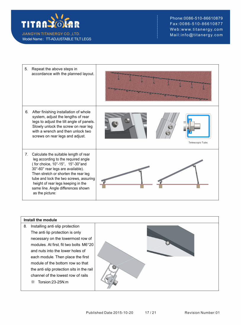
Install the module
Installing anti-slip protection
he anti-lip protection is only necessary on the lowermost row of modules. At first, fit two bolts M6*20 and nuts into the lower holes of
each module. Then place the first module of the bottom row so that the anti-slip protection sits in the rail
channel of the lowest row of rails
5. Repeat the above steps in accordance with the planned layout.
Telescopic Tubs
6. After finishing installation of whole system, adjust the lengths of rear legs to adjust the tilt angle of panels.Slowly unlock the screw on rear legwith a wrench and then unlock two screws on rear legs and adjust.
7. Calculate the suitable length of rear leg according to the required angle( for choice, 10°-15°,15°-30°and 30°-60° rear legs are available). Then stretch or shorten the rear leg tube and lock the two screws, assuring height of rear legs keeping in the same line. Angle differences shown as the picture:
8.
T
Model Name:TT-ADJUSTABLE TILT LEGS
Revision Number:01
※ Torsion: N.m23-25

Published Date 2015-10-20 18 / 21
JIANGYIN TITANERGY CO.,LTD.
Phone:0086-510-86610879
Fax :0086-510-86610877
Web :www. t i t ane rgy. com
Ma i l : i n fo@t i tanergy.com
10. Fixing the inter modules by inter clamp. a. Put the inter clamp kit into the
top channel of the TT -Rail as
the step 9. b. Push the Inter-module clamp
firmly against the already fixed module.
c. Push the next module against the other side of the
module-inter clamp. d. Tighten the bolt
11. Installing the further rows of modules
9. Fixing the outer modules by End clamp. a. Put the end clamp kit into the
top channel of the TT -Rail as
the step 9. b. Push the side of module to
firmly against the end clamp and then fasten the bolt.
Model Name:TT-ADJUSTABLE TILT LEGS
Revision Number:01
※ Torsion: N.m23-25
※ Torsion: N.m23-25

Cable tie and Grounding
12. Tie cable with the rail
a. Tie the cable with the rail using the zip tie
Published Date 2015-10-20 19 / 21
JIANGYIN TITANERGY CO.,LTD.
Phone:0086-510-86610879
Fax :0086-510-86610877
Web :www. t i t ane rgy. com
Ma i l : i n fo@t i tanergy.comModel Name:TT-ADJUSTABLE TILT LEGS
Revision Number:01
13. Grounding
Please see the Titan Solar Grounding
System Installation Guide.

10 . Warranty
Jiangyin Titanergy Co., Ltd. warrants that its Titan Solar Panel Mounting System is free from defects in materials and
workmanship for a period of 10 years from the date on which the Frame is purchased from Titan Solar, on the terms
set out in this warranty.
In the event that the Frame does not conform to this warranty during the Warranty Period, Titan Solar will,
at its option, either repair or replace the Frame or pay the cost of having the Frame repaired or replaced.
To the extent permitted by law, Titan Solar's total liability under this warranty will in no circumstances
exceed the repair or replacement of the Frame or payment of the cost of having the Frame repaired or
replaced. In the event of replacement of the Frame, any remaining part of the Warranty Period will be
transferred to the replacement Frame.
This warranty will not apply to any defect or damage to the Frame arising directly or indirectly from:
1.Shipment or storage of the Frame;
2.Improper installation, maintenance, repair or use of the Frame;
3. Normal wear and tear;
4. Misuse, neglect, abuse, accidental damage or modification to the Frame;
5. Failure to observe the instructions set out in the System Manual; or
6. Power failure, power surges, lightning, fire, explosion, flood, extreme weather conditions,
environmental disasters or other causes outside Grace Solar's control, as determined by Titan Solar in its
sole discretion.
This warranty does not cover, and under no circumstances will Titan Solar be liable for, any costs
associated with the removal, shipping, handling or re-installation of the Frame or the costs of sending
personnel to any site to repair or replace the Frame. This warranty is only provided to the original
purchaser of the TItan Solar panels mounting system (Purchaser) or, where the Purchaser is an installer or
builder who on-supplies the Frame to another party, to that other party (End-User). This warranty is not
transferable.
Where an End-User wants make a claim under this warranty, the End-User must in the first instance contact
the installer or builder from whom the Frame was purchased.
This warranty will not apply to any claims received by Titan Solar after the expiration of the Warranty
Period. Titan Solar makes no warranties, express or implied, other than the warranties made herein, and
specifically disclaim all other warranties, representations and conditions to the extent permitted by law.
To the extent permitted by law, in no circumstances will Titan Solar be liable for direct, indirect, special or
consequential damages arising from a defective Frame or for any damage or injury to persons or property.
Titan Solar's aggregate liability, if any, in damages or otherwise, will not exceed the invoice value of the
Frame at the time of purchase from Titan Solar.
Any provision contained in this warranty which is prohibited or unenforceable in any jurisdiction will be
deemed to be ineffective to the extent of such prohibition or unenforceability and will not invalidate the
remaining provisions nor affect the validity or enforceability of that provision in any other jurisdiction.
Published Date 2015-10-20 20 / 21
JIANGYIN TITANERGY CO.,LTD.
Phone:0086-510-86610879
Fax :0086-510-86610877
Web :www. t i t ane rgy. com
Ma i l : i n fo@t i tanergy.com
1. To be used only in combination with modules that include this specific rack system in their installation manual.
Fire Rated:
The minimum distance between module and roof is 8.5cm.
2. This racking system may be used to ground and/or mount a PV module complying with UL 1703 only when the
specific module has been evaluated for grounding and/or mounting in compliance with the included instructions.
C
Model Name:TT-ADJUSTABLE TILT LEGS
Revision Number:01

11 . Revision History
Table:Revision History
Revision Number Revision Date Reason for change Document Author
01 2015-10-20 Initial Release Josie
Published Date 2015-10-20 21 / 21
JIANGYIN TITANERGY CO.,LTD.
Phone:0086-510-86610879
Fax :0086-510-86610877
Web :www. t i t ane rgy. com
Ma i l : i n fo@t i tanergy.comModel Name:TT-ADJUSTABLE TILT LEGS
Revision Number:01


