27
WELCOME WELCOME EEERulez.BlogSpot.in

WELCOMEWELCOME
EEERulez.BlogSpot.in
SOLAR THERMAL SOLAR THERMAL
PROPULSIONPROPULSION
Presented by Presented by SHIJIN S KSHIJIN S K
S7 ME S7 ME Roll No Roll No
44194419
EEERulez.BlogSpot.in
INTRODUCTIONINTRODUCTION
STP conceived in 1956 by Kraft STP conceived in 1956 by Kraft Echrike.Echrike.
Space craft propulsion.Space craft propulsion. Does not require development of the Does not require development of the
power source.power source. STP system uses soar energy STP system uses soar energy
directly as heat.directly as heat.
INTRODUCTION INTRODUCTION (Contd…)(Contd…)
STP effectively bridges the STP effectively bridges the performance gap between chemical performance gap between chemical and electric propulsion.and electric propulsion.
Requires only one propellant.Requires only one propellant. Moderate thrust, propellant Moderate thrust, propellant
efficiency.efficiency. Hydrogen used as the propellantHydrogen used as the propellant
ELEMENTS OF STP ELEMENTS OF STP SPACE CRAFTSPACE CRAFT
Mainly 3 components.Mainly 3 components.
• ConcentratorConcentrator Sunlight concentrated by a Sunlight concentrated by a lens or mirror.lens or mirror.
• ThrusterThruster Heats and expands Heats and expands propellant to produce propellant to produce thrust.thrust.
• Propellant system.Propellant system.
Stores cryogenic propellant.Stores cryogenic propellant. ((diagram ) )

SOLAR SOLAR CONCENTRATORSCONCENTRATORS
Two concentrator designsTwo concentrator designs Rigid concentratorsRigid concentrators Inflatable concentratorsInflatable concentrators Applications of concentratorsApplications of concentrators
INFLATED INFLATED CONCENTRATORSCONCENTRATORS
It consists of two reflectorsIt consists of two reflectors Reflectors are symmetrical and Reflectors are symmetrical and
bounded at their edgesbounded at their edges Reflector components Reflector components
Reflective membraneReflective membrane Transparent membraneTransparent membrane ((fig ) )

Inflatable concentrator

ABSORBER AND ABSORBER AND THRUSTERTHRUSTER
Absorber function as a heat exchangerAbsorber function as a heat exchanger Transport of high intensity solar flux to Transport of high intensity solar flux to
the solar receiver via optical fiber cable.the solar receiver via optical fiber cable. Solar receiver core is made of graphite Solar receiver core is made of graphite
cylinder.cylinder. Graphite core is surrounded by the Graphite core is surrounded by the
molybdenum tube.molybdenum tube. Optical fiber cable – quartz rod.Optical fiber cable – quartz rod.
WORKING OF STP SPACE WORKING OF STP SPACE CRAFTCRAFT
STP system consists of two off axis STP system consists of two off axis solar concentrators.solar concentrators.
Optical waveguide transmission line.Optical waveguide transmission line. Propellant gas injected tangentially Propellant gas injected tangentially
into the graphite cylinder.into the graphite cylinder. Expansion through a nozzle.Expansion through a nozzle. ((
fig ) )

PROPELLANT HEATING PROPELLANT HEATING
Two ways to heat the propellant.Two ways to heat the propellant.
• Indirect Method.Indirect Method.
• Direct Method.Direct Method.
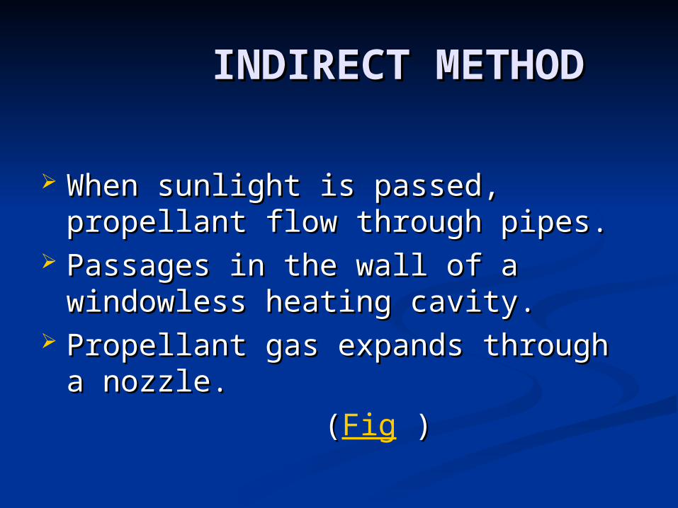
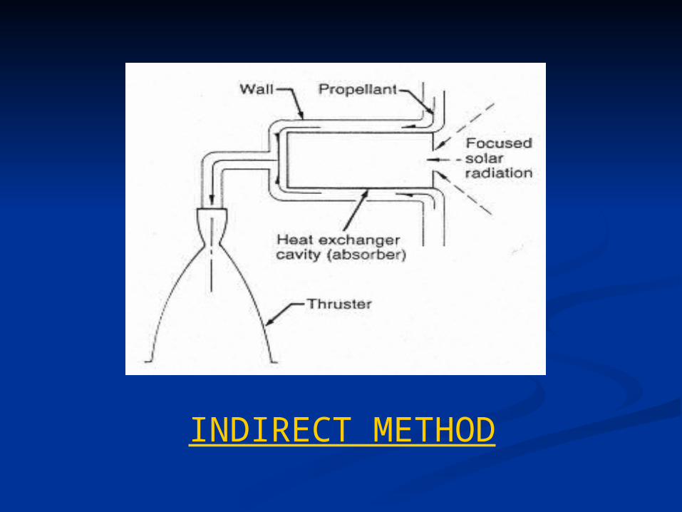
INDIRECT METHODINDIRECT METHOD
When sunlight is passed, propellant When sunlight is passed, propellant flow through pipes.flow through pipes.
Passages in the wall of a windowless Passages in the wall of a windowless heating cavity.heating cavity.
Propellant gas expands through a Propellant gas expands through a nozzle.nozzle.
((Fig ) )
INDIRECT METHOD

DIRECT METHODDIRECT METHOD
Propellant flow through windowed Propellant flow through windowed heating chamber.heating chamber.
Cylindrical rotating chamber rotates Cylindrical rotating chamber rotates so that centrifugal force keeps the so that centrifugal force keeps the sand or seeds.sand or seeds.
Choice of seeds.Choice of seeds.
((Fig ) )

DIRECT METHOD
SOLAR THERMAL SOLAR THERMAL PROPULSIONCONCEPTSPROPULSIONCONCEPTS
Two system level approachesTwo system level approaches Direct gain approachDirect gain approach Thermal storage conceptThermal storage concept

DIRECT GAIN CONCEPTDIRECT GAIN CONCEPT
Solar energy is collected by inflated Solar energy is collected by inflated concentrators. concentrators.
Use sunlight directly.Use sunlight directly. No need of thermal storage No need of thermal storage
medium .medium . Specific impulse is less.Specific impulse is less.
THERMAL STORAGE THERMAL STORAGE CONCEPTCONCEPT
It simplifies sun orientation and It simplifies sun orientation and sun tricklingsun trickling
Higher thrust with smaller Higher thrust with smaller concentratorsconcentrators
Thermal storage mediumThermal storage medium Specific impulse depends on Specific impulse depends on
storage temperaturestorage temperature

SPECIFICATIONSPECIFICATION
Propellant – hydrogen.Propellant – hydrogen. Maximum temp - 2300Maximum temp - 2300°K to 2400°K.°K to 2400°K. Chamber pressure – 20 to 25 psia.Chamber pressure – 20 to 25 psia. Nozzle area ratio – 100:1.Nozzle area ratio – 100:1. Thrust – 100 N.Thrust – 100 N. Specific impulse – 750 to 800 sec.Specific impulse – 750 to 800 sec.

COMPARISON OF COMPARISON OF DIFFERENT DIFFERENT THRUSTERSTHRUSTERS
Liquid thrusterLiquid thruster Solid thrusterSolid thruster Solar thermal thrusterSolar thermal thruster
TECHNOLOGIES UNDER TECHNOLOGIES UNDER DEVELOPING FOR STPDEVELOPING FOR STP
High temperature heat exchangersHigh temperature heat exchangers Low cost manufacturing of high Low cost manufacturing of high
performance componentsperformance components Long term cryogenic hydrogen Long term cryogenic hydrogen
storage storage Light weight, less rigid structuresLight weight, less rigid structures

BENEFITS OF SOLAR BENEFITS OF SOLAR THERMAL PROPULSIONTHERMAL PROPULSION
Higher payload fractionHigher payload fraction Higher specific impulseHigher specific impulse Higher thrust to weight ratioHigher thrust to weight ratio Space solar powerSpace solar power Low cost for interplanetary travel Low cost for interplanetary travel
and unmanned explorationand unmanned exploration
LIMITATIONS OF SOLAR LIMITATIONS OF SOLAR THERMAL PROPULSIONTHERMAL PROPULSION
Relatively lower thrustRelatively lower thrust Less efficient places where sunlight Less efficient places where sunlight
intensity lowintensity low Ground level testingGround level testing
CONCLUSIONCONCLUSION
Less expensive, much simpler, more Less expensive, much simpler, more efficient.efficient.
Missions to the moon and mars as well Missions to the moon and mars as well as boosting payloads to higher orbit.as boosting payloads to higher orbit.
Solar absorber, thruster and inflated Solar absorber, thruster and inflated concentrated technology development concentrated technology development have continued to be advanced under have continued to be advanced under AFRL over the last 20 years.AFRL over the last 20 years.

THANK THANK YOUYOU
EEERulez.BlogSpot.in


