43
Solid State Navigation and Situation Awareness Radar

Solid State Navigation and Situation Awareness Radar

1904
Radar
2000200019001900 19501950
2008
1948- present

Origins of Commercial Marine Radar
Kelvin Hughes New Marine Radar 1948Type 1• First UK Type Approved Marine
Radar– 11th August 1948
• Specification– Upmast Transmitter/Receiver– Antenna Rotation: 30RPM– Peak Power:- 30kW– RF Frequency:- 9.434GHz -
9.524GHz– PRF:- 1kHz– Pulse Width: 0.2μs– Azimuth Beamwidth:- 1.5°– Elevation Beamwidth:- 27°

Sensor ImprovementsAdvances in Sensor Technology
Low Noise Front EndsFET ModulatorsImproved Magnetron Life
Current Sensors at Peak of PerformanceHowever………
Little improvement in performance in clutterCustomers & Regulators demand detection of smaller targetsCustomers want more reliable systemsPressure from ITU to restrict radar bandwidth and out of band emissions
-100
-90
-80
-70
-60
-50
-40
-30
-20
-10
0
2 4 6 8 10 12 14 16
Pow
er (d
Bc/
Hz)
Frequency (GHz)
Magnetron - Short Pulse Spectrum

• First ‘New Technology’ Marine Navigation Radar for 60 years• Conforms to requirements of IMO & IEC• ‘Family’ of Products
– Built-in Flexibility through design and part selection– Considered future enhancements during concept/design phase– 100% PV Funded Development
• Performance/Cost Trade-Off– Minimum performance IEC 62388 (new radar standard - July 2008)
• More performance expected but not at expense of production cost/quality• Achieve performance through innovation
– Economies of scale• Re-use of components/sub-assemblies throughout product range
• Reliability and Maintainability high on our priorities
SharpEye Introduction

Features include:
•Solid state transmitter
•Coherent transmitter and receiver
•Pulse compression
•Digital signal processing
•Interference suppression
•Low voltage operation
World’s 1st Solid State Marine Navigation Radar
SharpEye

• Incorporates advantages in semi-conductor based radars but at a cost that competes with conventional magnetron systems
• Sharpeye incorporates low power RF architecture.
• Sharpeye outputs a clever frame of transmission pulses in a specified sequence
• Utilises Doppler processing techniques
What sets Sharpeye apart

New Technologies - Solid State Transmitter
• Solid State Transmitter– Uses transistors instead of a
magnetron– >200W peak power @ 13% duty– Coherent
• RF transmissions have consistent phase & timing relationship
– Controlled RF Spectrum• ITU Compliance
– Selection of 12 RF frequencies• Extremely stable oscillators
– No tuning necessary
– Digital Waveform Generation• Direct Digital Synthesis

Traditional Magnetron Radar
Narrow pulse30,000W

Revolutionary Performance
Long Pulse200W

Since…
Energy = power X time
…by significantly increasing the length of the pulse, the total energy leaving the aerial is more than equivalent to the energy leaving a 30kw system despite the peak pulse being reduced by more than 99%.

-120
-100
-80
-60
-40
-20
0
20
40
0.000002 0.000004 0.000006 0.000008 0.00001 0.000012 0.000014 0.000016 0.000018
Revolutionary Performance
170W Coherent Signal

SharpEye
Long Pulse with Pulse Compression170W
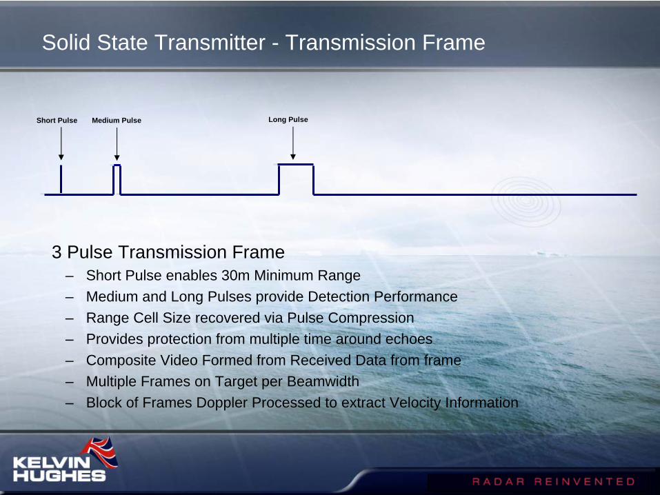
Solid State Transmitter - Transmission Frame
3 Pulse Transmission Frame– Short Pulse enables 30m Minimum Range– Medium and Long Pulses provide Detection Performance– Range Cell Size recovered via Pulse Compression– Provides protection from multiple time around echoes– Composite Video Formed from Received Data from frame– Multiple Frames on Target per Beamwidth– Block of Frames Doppler Processed to extract Velocity Information
Long PulseMedium PulseShort Pulse

Frequency Diversity - Transmission Frame
Diversity Transmission Frame– Additional Pulses inserted into frame– Second receiver channel and signal processor added– 30m Minimum Range maintained– Channels processed independently & combined– Improved detection & clutter performance– Small improvement in multipath
Long PulseMedium PulseShort Pulse

SharpEyeTM - Solid State Transmitter
Pulse Energy Comparison
0
0.005
0.01
0.015
0.02
0.025
0.03
0.035
SP 24nm MP 48nm LP 96nm
Pulse Type
Pul
se E
nerg
y (m
J)
•Transmissions– Pulse Energy
• Energy in pulse limits detection range, NOT peak power
– Minimum range• For monostatic radar pulse duration
defines minimum range– IEC 60936 states 50m (333ns)
– Complex pattern of 3 pulses/frame• Provides energy for detection and meets
minimum range constraint• Allows detection of targets close to clutter
– Three Transmission Frame Types• 24nm Instrumented range• 48nm Instrumented range• 96nm Instrumented range
SharpEyeTM
Magnetron Radar

Digital Signal Processor - Range Measurement
Pulse Compression converts long pulses into narrow range cells– Range Cell Size maintained over entire instrumented range– Short range performance in clutter and long range detection performance
Pulse Frame characteristics determined by Range Mode/Rotation Rate– Appropriate pulse length automatically selected– Reduced operator loading
Instrumented Range is independent of Range Display Setting– Enables Tracking of target out to Instrumented range (e.g 24nm) regardless of
display settingLinear receiver
– Pulses are not stretched as in a logarithmic amplifier

Digital Signal Processor Velocity Measurement
SharpEyeTM determines Target Velocity via Doppler Processing
Conventional RadarTargets must have an amplitude larger than the clutter to be detected• Clutter controlled by raising threshold - small targets disappear
Sharpeye Monostatic Pulse RadarTargets and clutter are separated by measuring the radial velocity of target• Frequency shifts in the returned signal helps to distinguish between target
and clutter• FFT or MTD Doppler Processing mechanisms available
– MTD enables variation in filter characteristics across velocity space• Flexibility of implementation provides potential for future growth
– Adaptive MTD

Performance: In Clutter
TargetRain
Land
Sea
0
-10
-20
-30
-6 0 6 12 18 24
Power (db)
Velocity (m/s)

SharpEye™ Pulse Doppler
Doppler Map– Echoes from 1 burst (32 pulses)
• Data obtained from Hainault area in September 2005
– X axis (Horizontal)» Radial Velocity
– Y axis (Out of Page)» Range
– Z axis (Vertical)» Signal Amplitude
– Central Ridge• Ground Clutter (zero velocity)
– Right Half Plane (+ve velocity)• Two Targets

RF Front End
Signal Generator Digital Signal Processor
Receiver
Solid State Transceiver - Physical Implementation

• Internally 4 Layers– RF Front End
• Power Amplifier• Circulator• Low Noise Amplifier
– Signal Generator• Coherent Oscillators• DDS Waveform Generator• Up Converter
– Receiver• Down Converter• Analogue to Digital Converter
– Digital Signal Processor• Pulse Compression• Doppler Processing• CFAR & Detection• Video Output & Control
Solid State Transceiver - Physical Implementation

• Solid State Radar for Naval & Coastal ApplicationsS Band (2.9-3.1 GHz) and X Band (9.0-9.7 GHz)Upmast Systems
Unstabilised AntennaElectronics HousingTransceiver
Conduction cooledFunctionally equivalent
Frequency Dependent variations Multi-Mode Digital Signal Processor
Doppler Processing enables Velocity MeasurementHigh ReliabilityFlexible Design for Future Growth
Product Description

TX NOT READYTx has 2 stage start up. VSWR is checked before Tx goes to full power.
NO H/L. Will show up if antenna not turning or if the Heading Line circuits are faulty.
NO AZIMUTHWill show up when scanner stopped or when azimuth pulse circuits are faulty
NO SYNCWill show up when the Tx stops or when the Trigger circuits go faulty
NO VIDEOWill show up when the transmitter is not running or when there is a fault in the receiver circuits
TX POWERWill show up when the transmitter is running at half power.
VSWRWill show up when the transmitter output detects a poor VSWR
Examples of SharpEye BITE

•Surface Picture Modes– Primary System Modes– Defined by Instrumented Range (24nm & 48nm)– Operator Selection via Display
•Rotation Rate– Supports 12rpm, 24rpm, 46rpm Nominal Rates– Custom Waveform Design for Rotation Rate/Range Mode
•Sub-functions– Reduced Power
• 7dB Reduction in Peak Power– Reverse Sweep
• Reversed Pulse Modulation in Transmit
Standard System Modes and Sub-functions

System Modes - Incremental Capability Growth
•Flexible Design enables Incremental Capability Growth– Helicopter Tracking Mode
• Higher Maximum Unambiguous Velocities (Up to 300 Knots)• Reduced Instrumented Range (10 nm)
– Short Range Mode• Low Power Mode • Modified Transmission Waveform• Reduced Instrumented Range (3-4 nm)• Designed for Close In/Harbour Operation
– Frequency Diversity• Provision made for Auxiliary RF Channel in Receiver• Custom Transmission Waveform and Signal Processing

Reliability, Maintainability, Availability
– Reliability• Transceiver >50,000 hours
– >5 years continuous use (24/7)– Maintainability
• Continuous Monitoring– Peak Power, VSWR and Receiver Sensitivity– Automatically alarms when outside specified limits– Graceful degradation
• Repair Philosophy– Replacement of Major Unit– Mean Time To Repair < 1 hour
– Availability• Transceiver
– 99.995%

SharpEye™ S Band (NATO F Band) Radar
• Solid State– Transistor Power Amplifier Replaces
Magnetron» High Reliability & No ‘Lifed’ Items» Low Voltages 36v max.
– Low Peak Power 170W min, 200W typically
» Pulse Compression Recovers Range Resolution
» Triggers RACONs
• Optional Pulse Doppler variant – Coherent– Separates targets from clutter
• IMO compliant to current and ‘new’ (2008) standards

SharpEye™ S Band (NATO F Band) Radar
Cost vs Performance Comparison
Performance• Exceeds magnetron radars in almost all
conditions
Cost• Acquisition• Comparable with a magnetron system• Through-life• Less than a magnetron system
10m2 target sea state 5 and heavy clutter conditions
0.5m2 target sea state 5 and heavy clutter conditions

S Band SharpEye™ in Gothenburg

Comparison: S Band SharpEye™ with 25kW X Band Magnetron Radar

S Band SharpEye™ in Gothenburg

Conclusions
SharpEye - the first ‘New’ marine radar since 1948Technology “borrowed” from military systems
Designed to meet IMO performance standards – Cost a major design driver
Reliability not performance the customers prime interest

Ting Kau Bridge

SharpEye™ X Band (NATO I Band) Radar
– Solid State• Transistor Power Amplifier
– High Reliability & No ‘Lifed’ Items– Low Voltages 15v max.
• Peak power 170W min, 200W typ– Pulse Compression Recovers Range
Resolution– Triggers RACONs & SARTs
• Operational frequency– 9.0 GHz - 9.5 GHz– IMO compliant over band 9.2 GHz - 9.5GHz
– Pulse Doppler– Coherent– Measures the radial velocity of targets– Separates targets from clutter

SharpEye™ X Band (NATO I Band) Radar
•Cost vs Performance Comparison•Performance
• Exceptional in its class• Exceeds magnetron radars in
almost all conditions– Cost
• Acquisition– Comparable with a
magnetron system• Through-life
– Less than a magnetron system
10m2 target sea state 5 and heavy clutter conditions
0.5m2 target sea state 5 and heavy clutter conditions

Conventional X Band
Range 3nm TX MagETD OffWeather SnowSea 4

Sharpeye X Band
Range 3nm TX Solid State
Weather SnowSea 4

Range 1.5nm TX Solid StateWeather ClearSea 3
Range 1.5nm TX MagnetronWeather ClearSea 3

Range 1.5nm TX MagnetronWeather ClearSea 3

Range 1.5nm TX Solid StateWeather ClearSea 3

SharpEye™ - Coastal Surveillance & VTS
•Coastal– S Band
• High reliability• Excellent performance in weather• Frequency diversity
– X Band• High reliability• Good performance in weather• Frequency diversity• High angular resolution
– Dual Band• S & X in a single turning unit
– Detection of small boats•Vessel Traffic Management
• S or X band• Ports and harbours

• Solid state technical sensor that meets latest requirements for situational awareness, navigation safety, small target detection and helicopter tracking in high clutter
• Technology “borrowed” from military systems but delivered in a commercial cost effective system
• Designed to meet /exceed IMO performance standards
• Uses latest signal and graphic processing technology
• Software upgradable – future enhancements planned
• Low maintenance
• Low through life costs
Sharpeye System Summary


![Nippon Denko Compendium 2017eng).pdf · Nippon Denko Compendium 2017 ... additives for laminated ceramic capacitors, ... [European market and FV]; TEX Report [others]) Product prices](https://static.documents.pub/doc/80x56/5b5bef057f8b9a68368bb676/nippon-denko-compendium-engpdf-nippon-denko-compendium-2017-additives.jpg)


