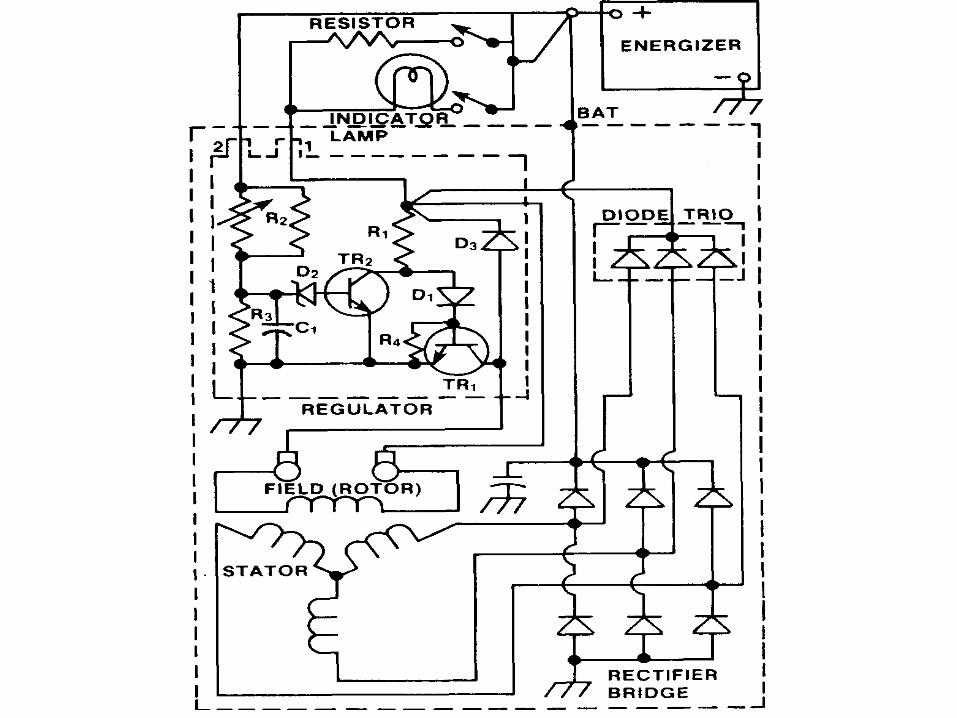
68
Solid State University Understand the following components: Potentiometers Thermistors Capacitors Diodes Zener Diodes Transistors
| Date post: | 18-Dec-2015 |
| Category: |
Documents |
| Upload: | doris-cross |
| View: | 231 times |
| Download: | 2 times |
Solid State University Understand the following components:
Potentiometers
Thermistors
Capacitors
Diodes
Zener Diodes
Transistors
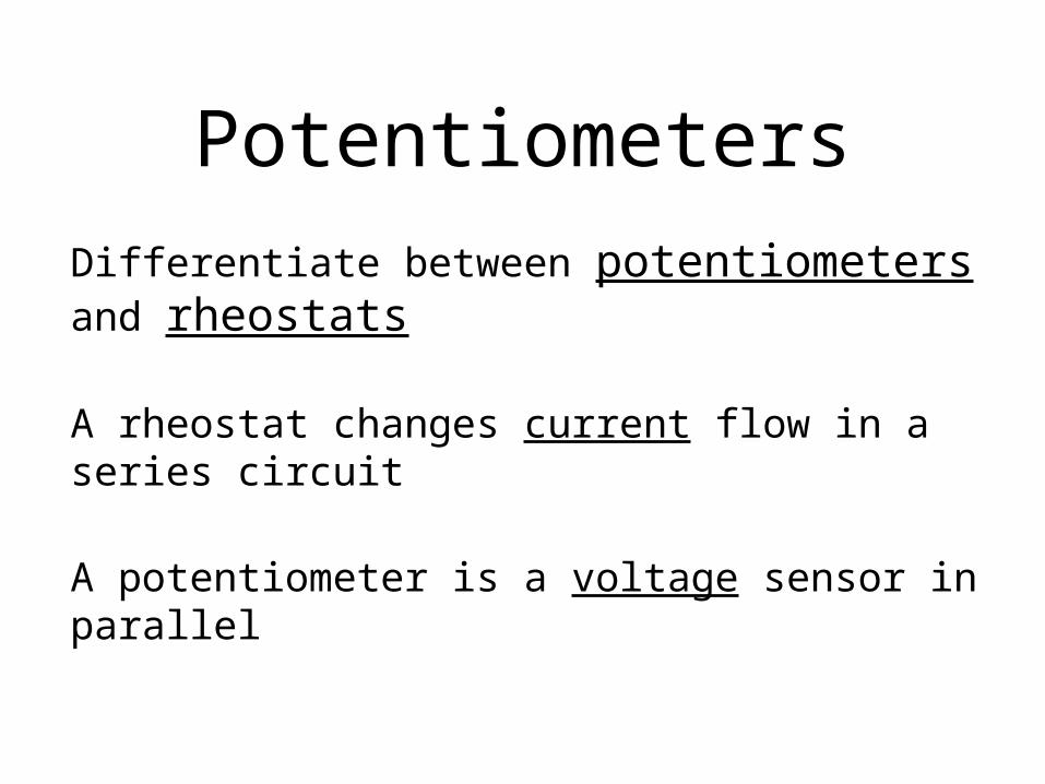
Potentiometers
Differentiate between potentiometers and rheostats
A rheostat changes current flow in a series circuit
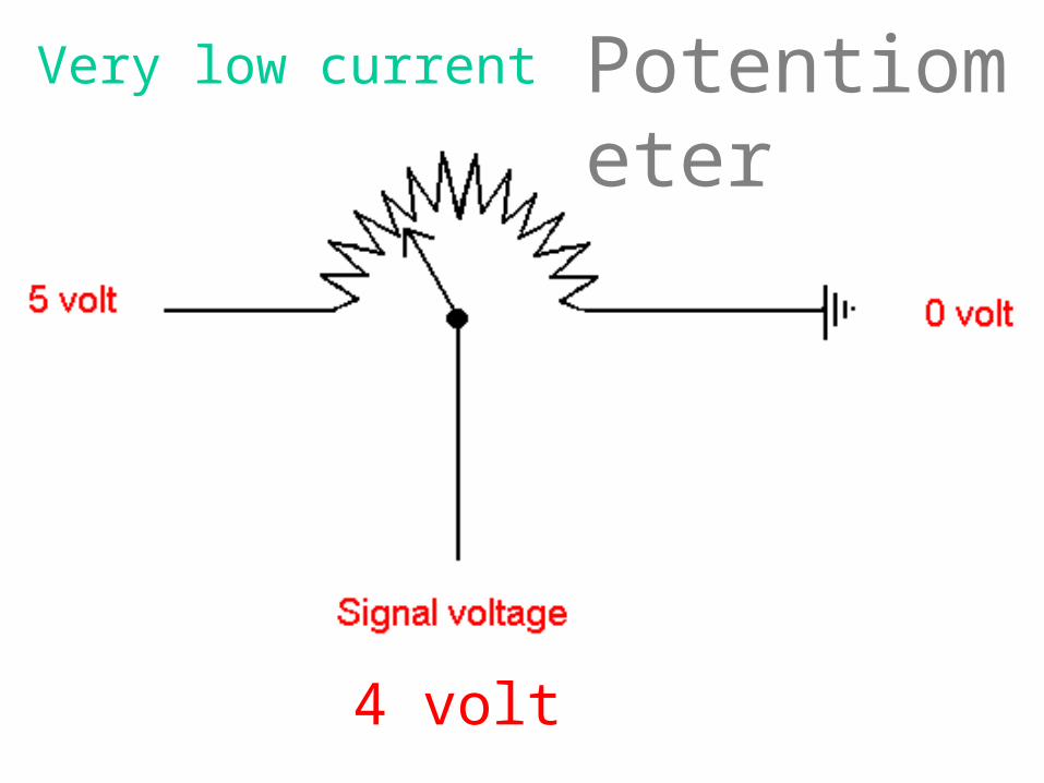
A potentiometer is a voltage sensor in parallel
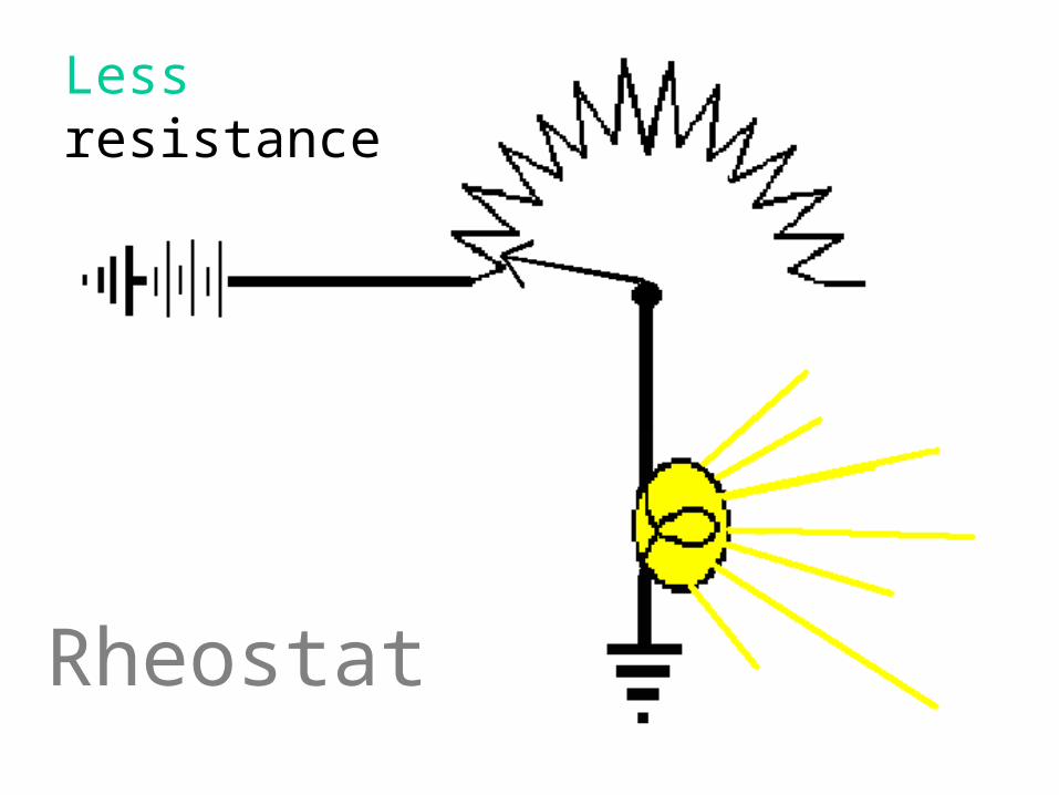
Rheostat
Less resistance
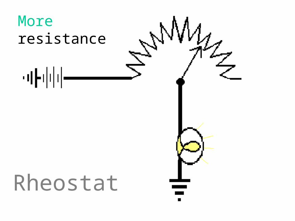
Rheostat
More resistance

Potentiometer
4 volt
PotentiometerVery low current

2 volt
PotentiometerUsed as a sensor
2.5 volt(should be 2 volt)
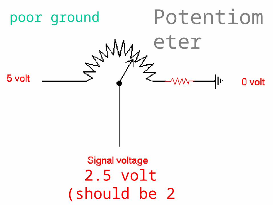
Potentiometerpoor ground

5 volt(should be 2 volt)
Potentiometeropen ground

Rheostats are wired in series with the load
their purpose is to change amp flow
Potentiometers sense motion
check for: reference voltage
good ground
un-interrupted signal
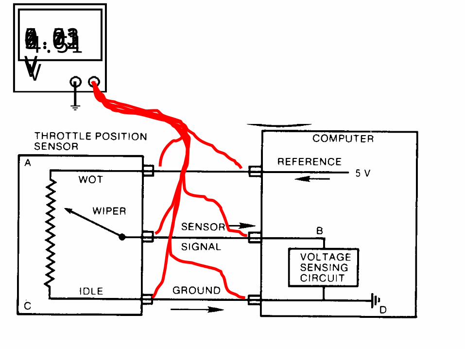
5.03 V5.02 V4.51 V4.51 V0.01 V0.01 V

4.52 V0.52 V
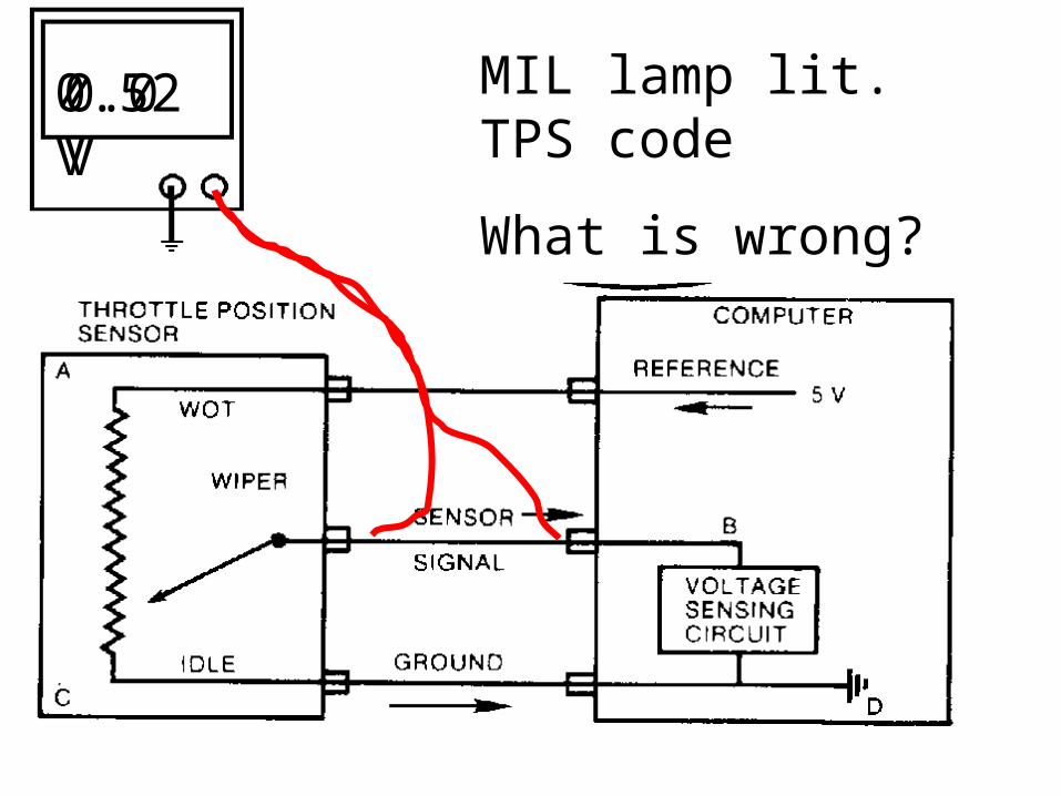
0.52 V0.0 V MIL lamp lit. TPS code
What is wrong?
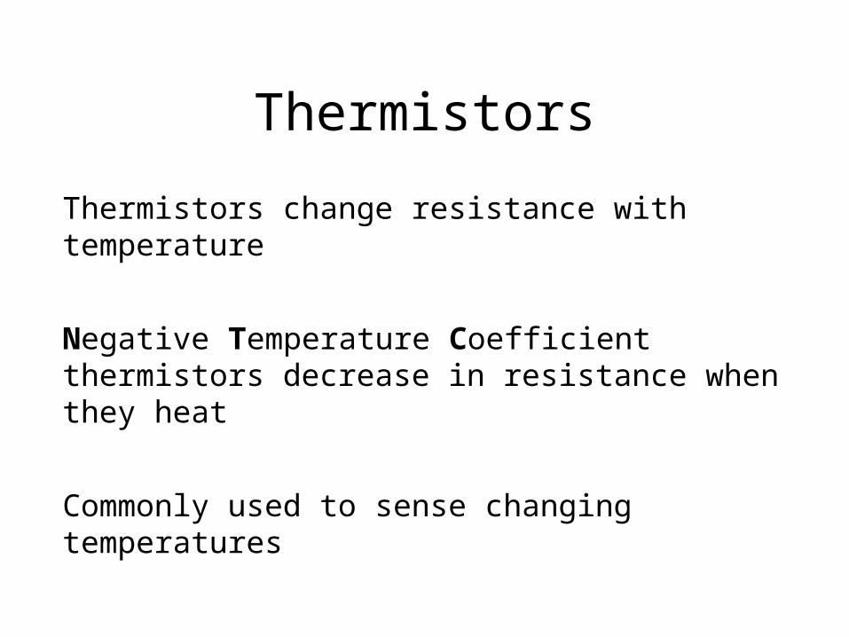
Thermistors
Thermistors change resistance with temperature
Negative Temperature Coefficient thermistors decrease in resistance when they heat
Commonly used to sense changing temperatures

High Resistance when Cold!
Low Resistance when Hot!
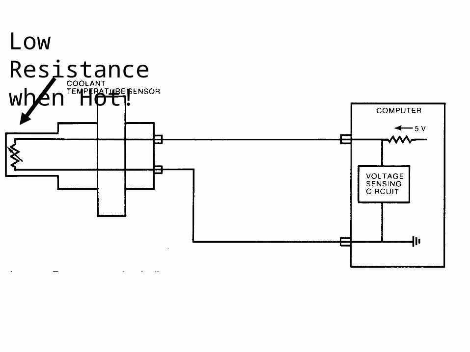
4.52 VHot or Cold?COLD!
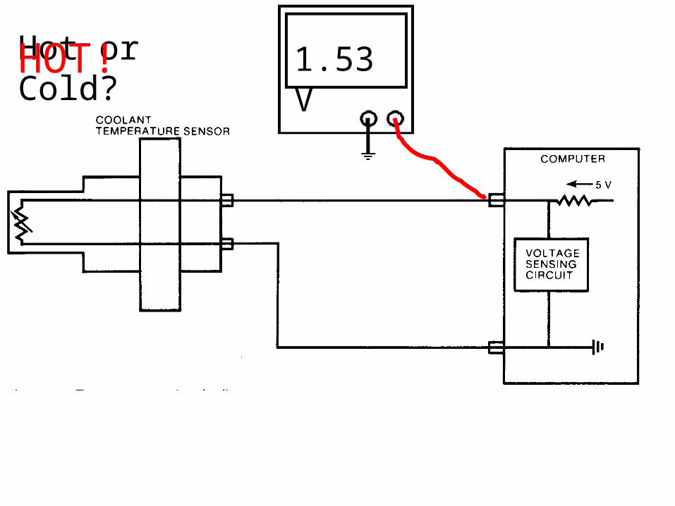
1.53 VHot or Cold?HOT!
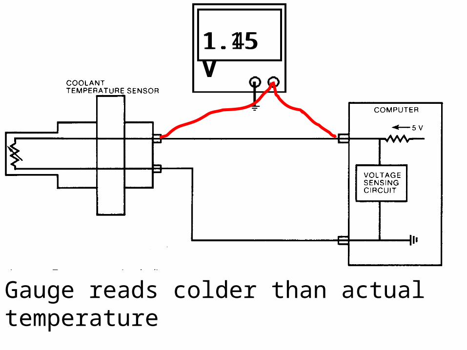
1.45 V1.15 V
Gauge reads colder than actual temperature

0.49 V0.02 V
Gauge reads colder than actual temperature
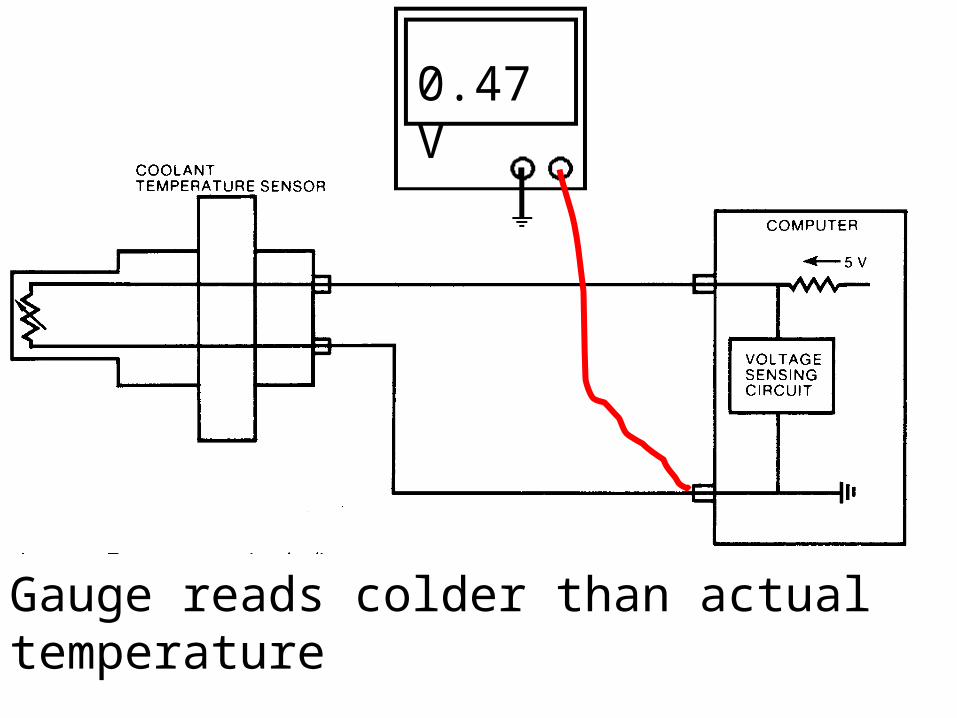
0.47 V
Gauge reads colder than actual temperature
Thermistors
Thermistors are checked with an Ohmmeter or a Voltmeter
A temperature probe or thermometer should be used when checking
Capacitors
Capacitors store an electrical charge
Capacitors provide an alternate path for electrons and act as a current “shock absorber”
Capacitors are commonly used to suppress noise
alternators
coils
motors

Capacitors
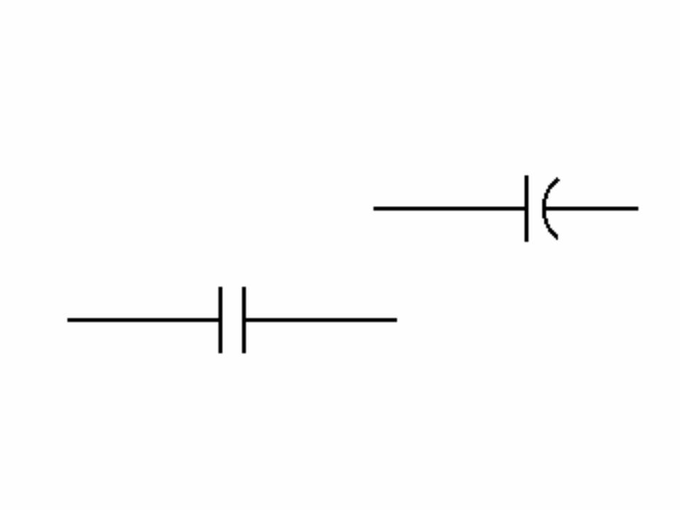
Capacitors are rated in microfarads
Capacitors are connected in parallel with a load
they can be checked with an ohmmeter for short or open circuits
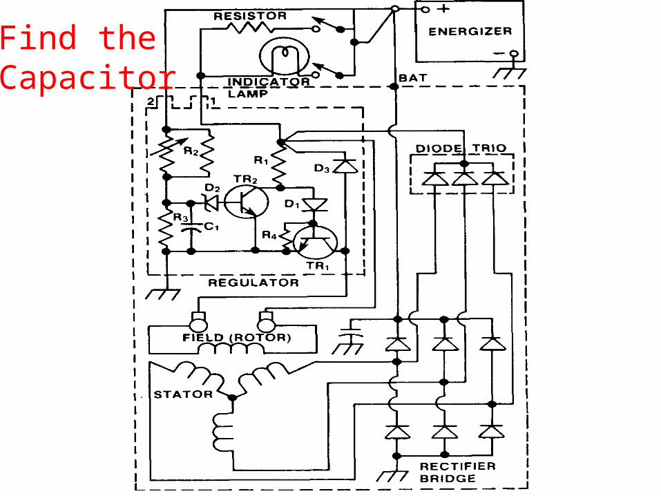
Find the Capacitor
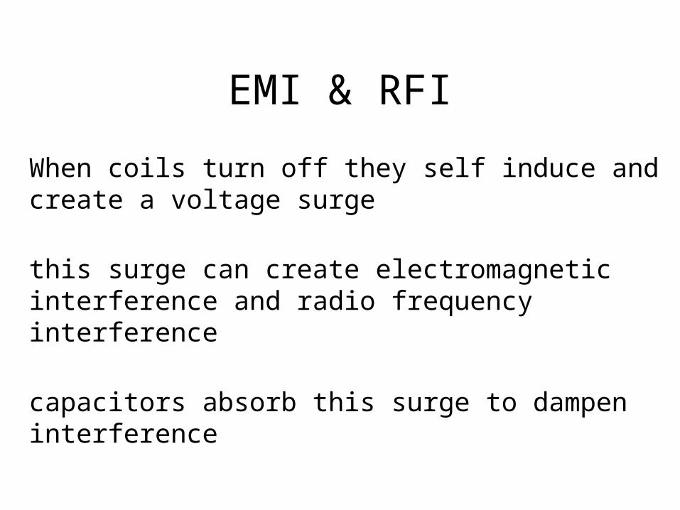
EMI & RFI
When coils turn off they self induce and create a voltage surge
this surge can create electromagnetic interference and radio frequency interference
capacitors absorb this surge to dampen interference
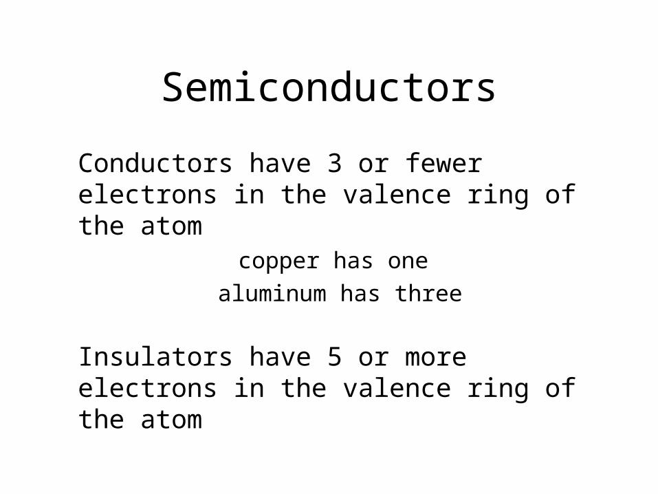
Semiconductors
Conductors have 3 or fewer electrons in the valence ring of the atom
copper has one aluminum has three
Insulators have 5 or more electrons in the valence ring of the atom

Semiconductors
Elements with four valence electrons are not good as insulators or conductors
Silicon, when is a crystal form, shares valence electrons to make a good insulator
Silicon can be “doped” to add electrons to the valence ring or remove electrons from the valence ring

Semiconductors
Silicon doped with phosphorous (which has
five electrons in the valence ring) will create an “N” type semiconductor
Silicon doped with boron (which has three
electrons in the valence ring) will create a “P” type semiconductor
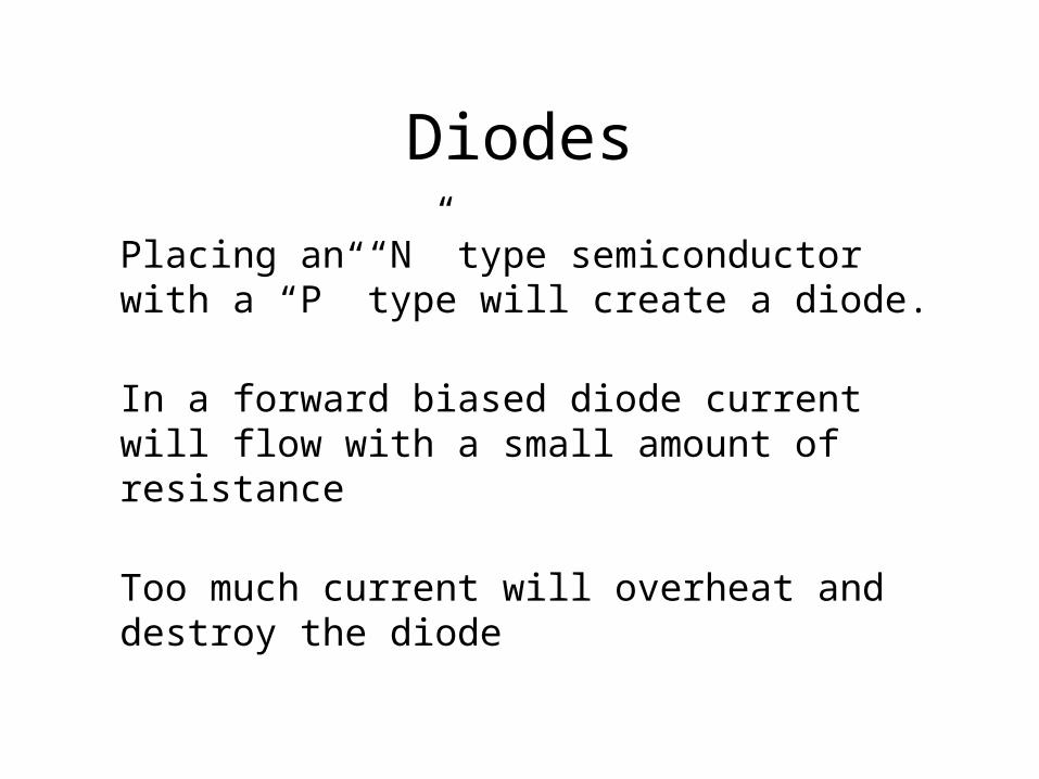
Diodes
Placing an “N” type semiconductor with a “P” type will create a diode.
In a forward biased diode current will flow with a small amount of resistance
Too much current will overheat and destroy the diode

Diodes
Reverse biasing a diode will create very high resistance at the center of the diode and current will not flow
Too much voltage will overcome the internal resistance and the diode will short out
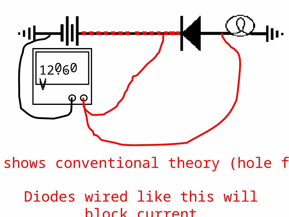
12.6 V 0.0 V
Arrow shows conventional theory (hole flow)
Diodes wired like this will block current

Arrow shows conventional theory (hole flow)
Diodes wired like this will allow current to flow with a slight voltage drop
12.6 V12.0 V 0.1 V
Testing Diodes
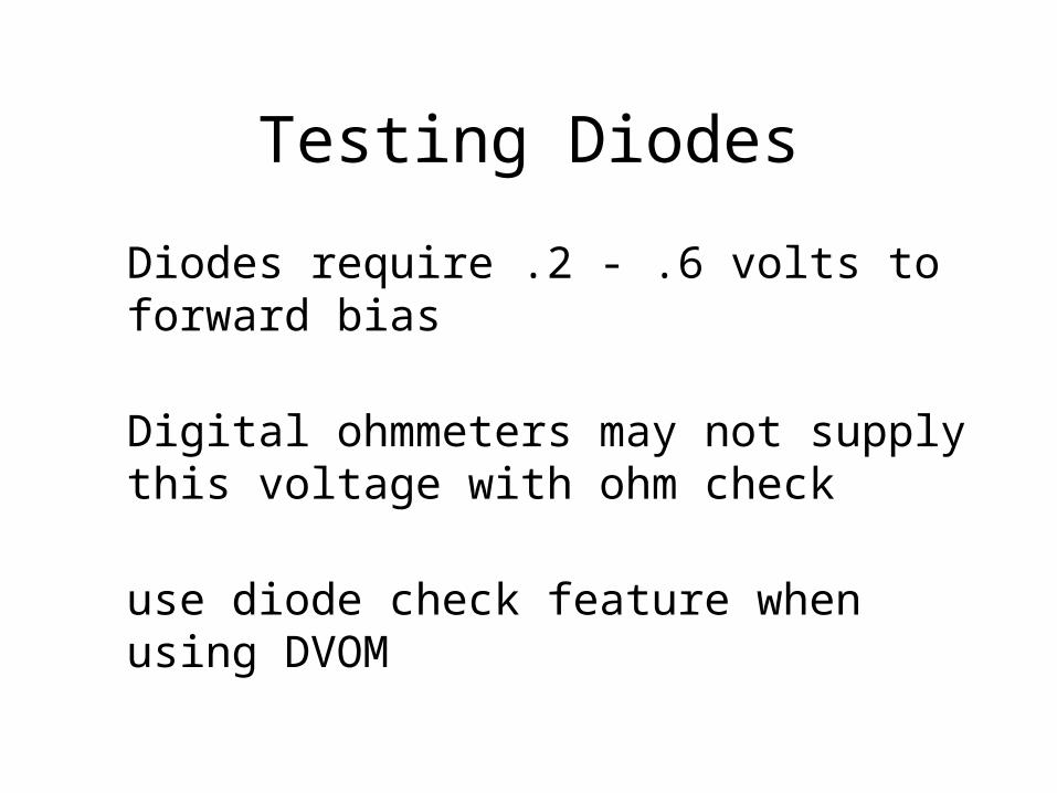
Diodes require .2 - .6 volts to forward bias
Digital ohmmeters may not supply this voltage with ohm check
use diode check feature when using DVOM
Testing Diodes
Shorted diodes on alternators will allow A/C voltage that may confuse a control module
Routine checks with oscilloscope are easy
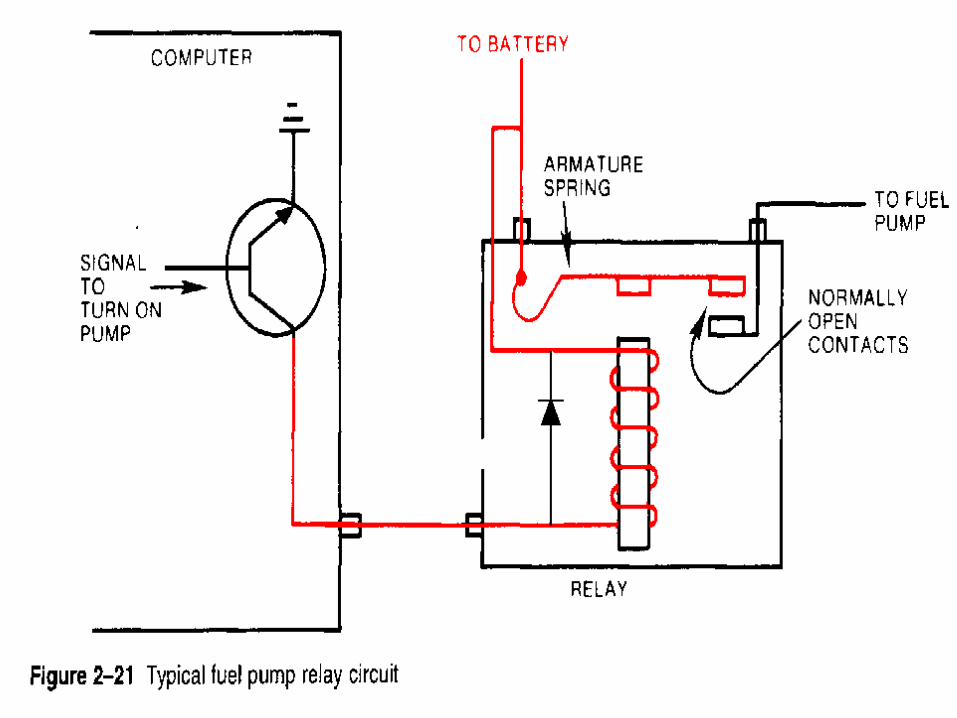
Anti- Spike Diodes
Clamping or Anti-Spike diodes protect sensitive control modules

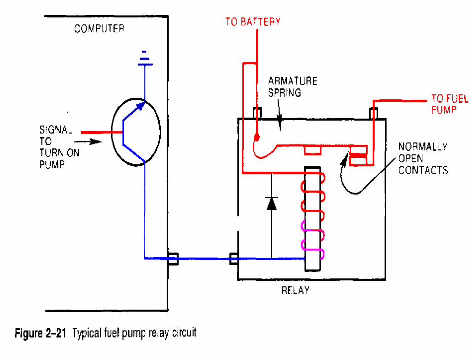
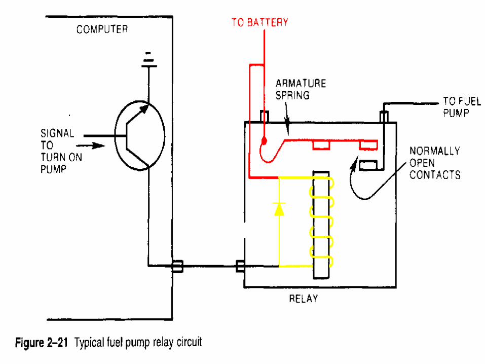

Anti- Spike Diodes
Functioning anti spiking diodes will exhibit un-equal resistance when reversing polarity (using an analogue meter)


Failure in Anti- Spike Diodes
An open, or shorted diode will damage computer control modules
Open diodes allow spike voltages to harm electronic components
Shorted diodes (and relay coil windings) will cause too much current to flow and burn out switching transistors in computers
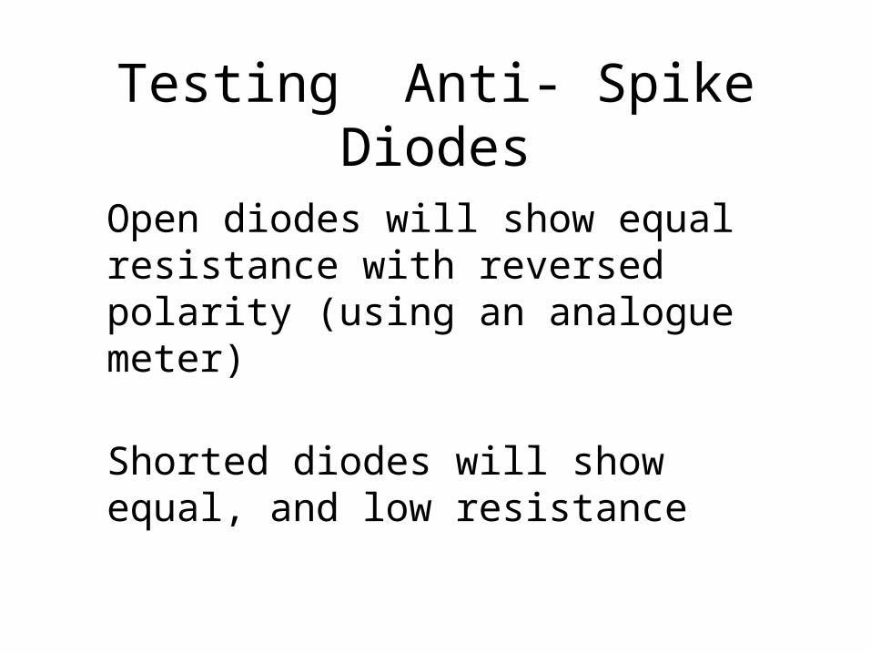
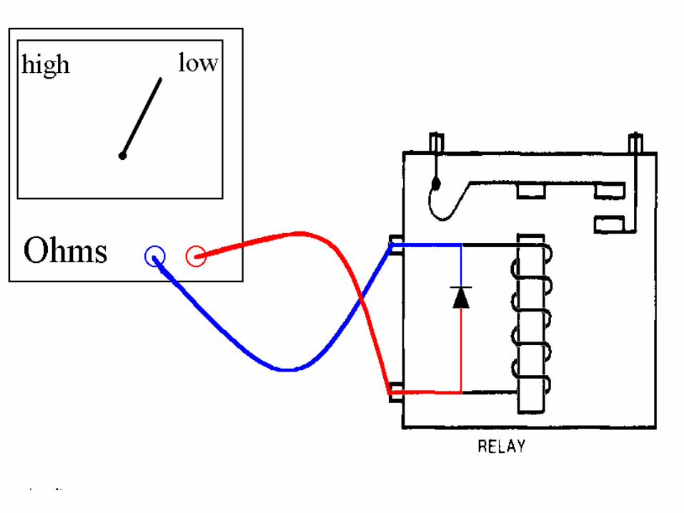
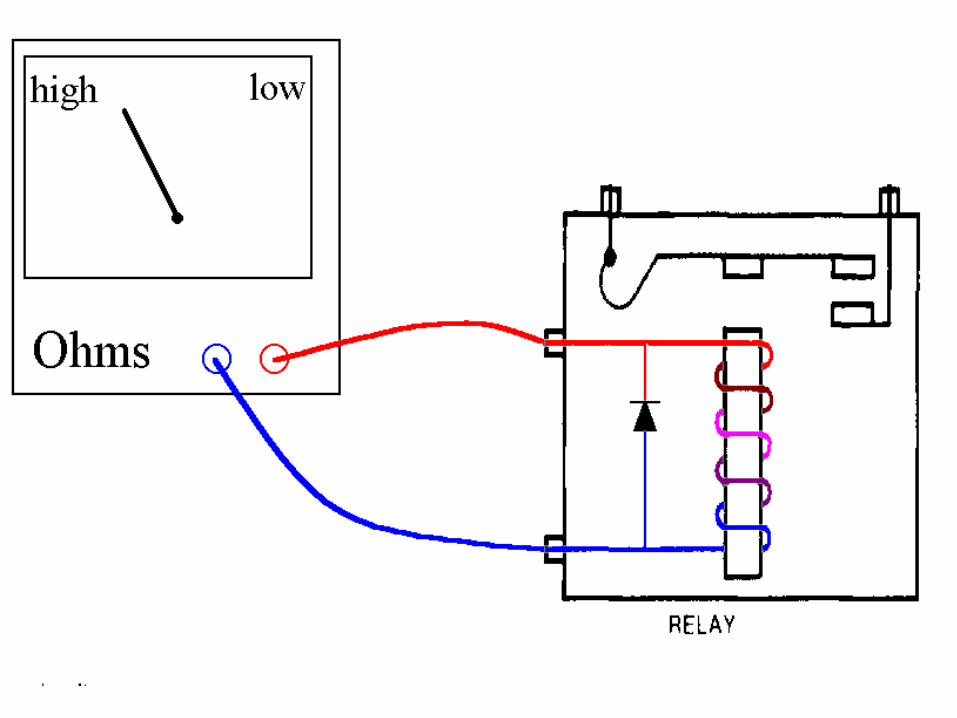
Testing Anti- Spike Diodes
Open diodes will show equal resistance with reversed polarity (using an analogue meter)
Shorted diodes will show equal, and low resistance


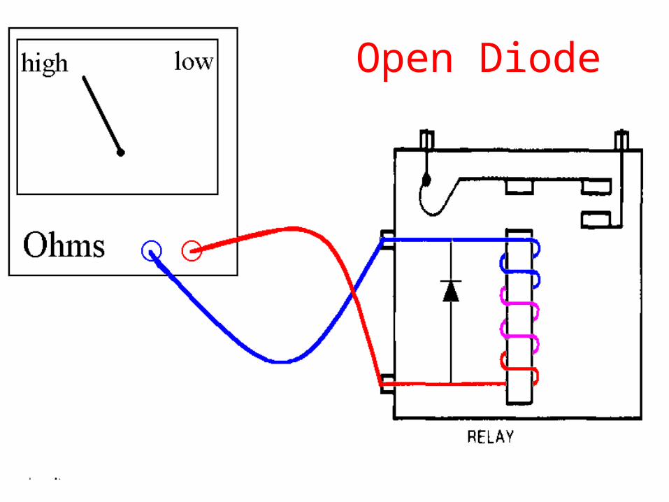
Open Diode

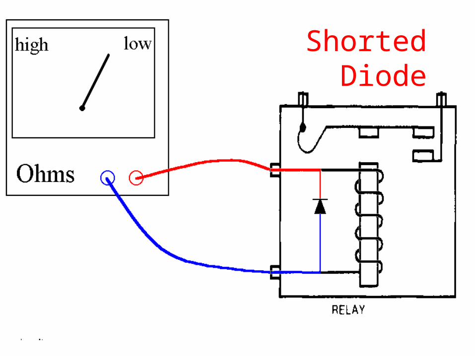
Shorted Diode
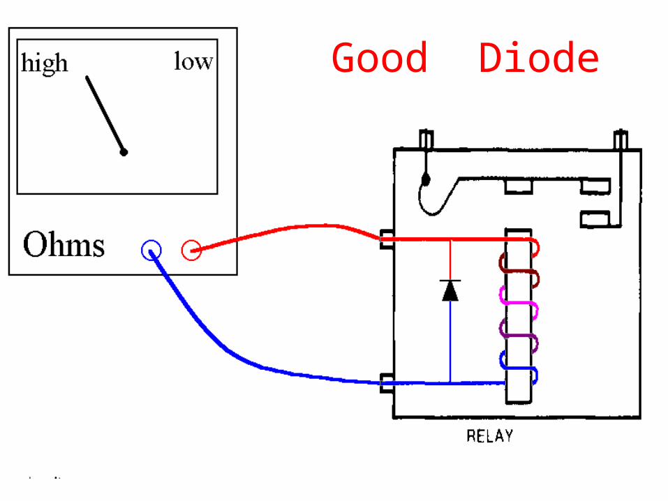
Good Diode
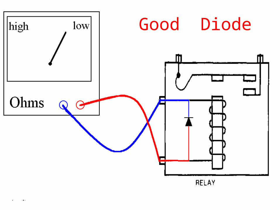
Good Diode
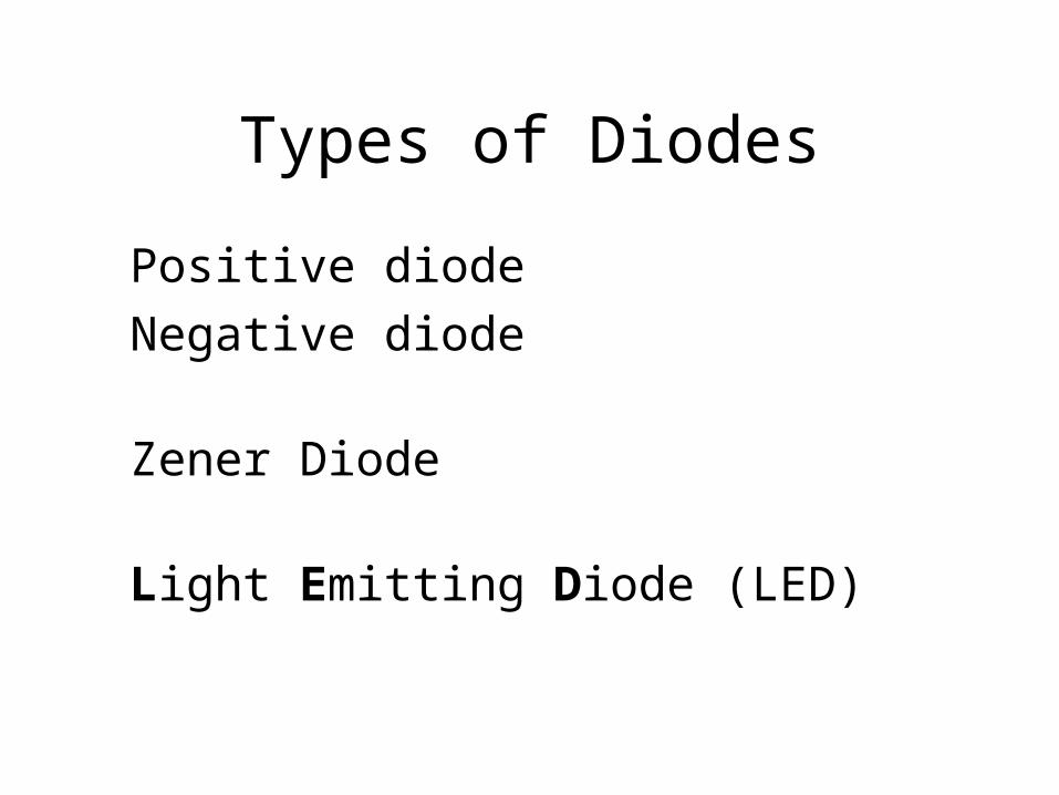
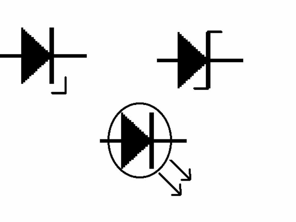
Types of Diodes
Positive diode
Negative diode
Zener Diode
Light Emitting Diode (LED)

Transistors
Transistors can act as a relay they use a small signal current to control
a larger working current
Transistors can act as a signal amplifier

PNP transistor
Points In Permanently
Will conduct current when the base sees a Negative polarity

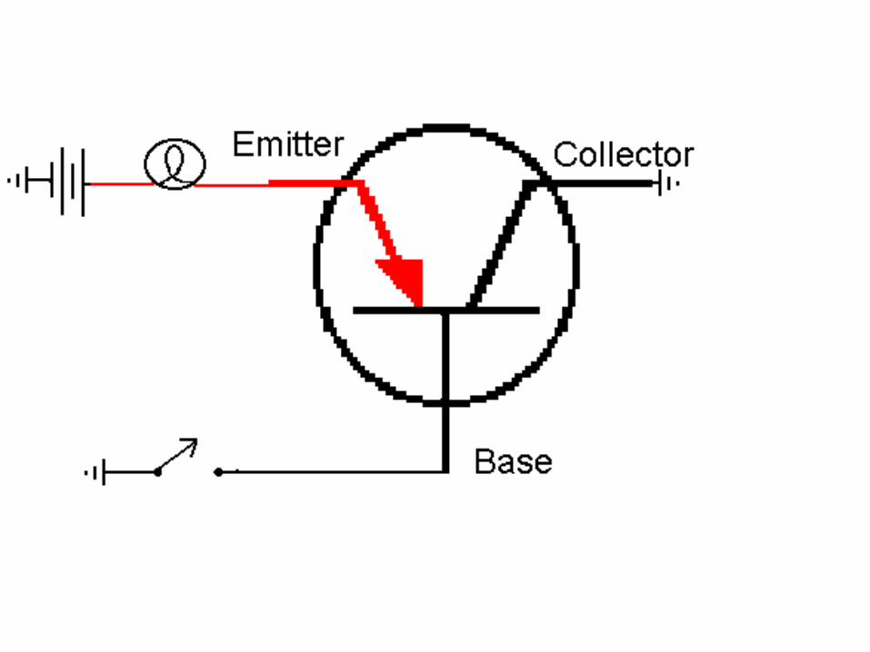
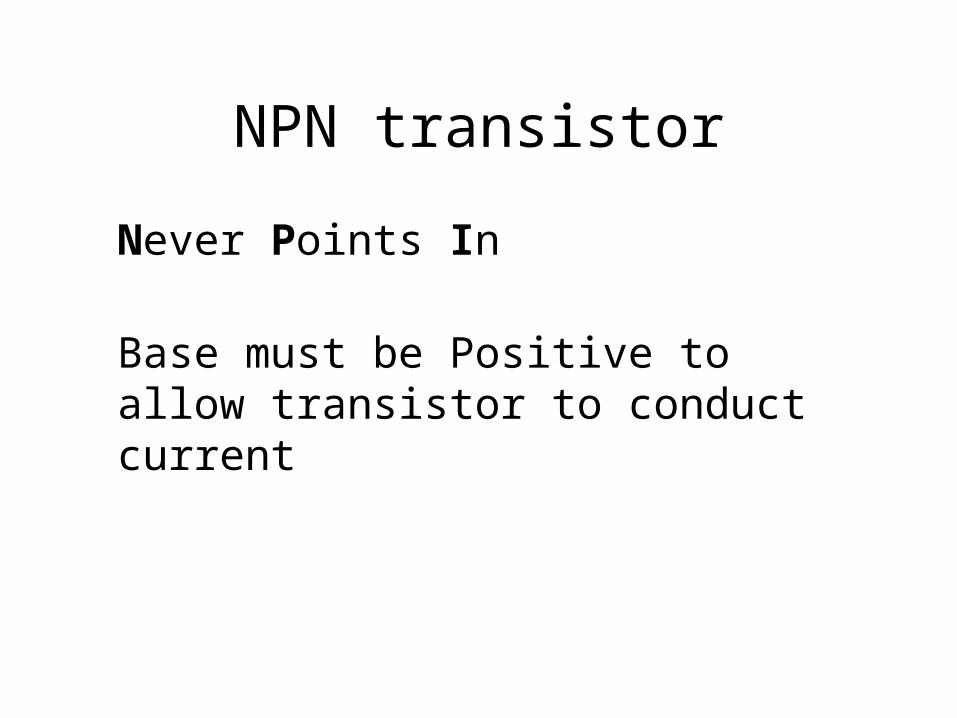
NPN transistor
Never Points In
Base must be Positive to allow transistor to conduct current


Transistors
Transistors are damaged by too much current
Transistors are damaged by high voltage