www.scion.lk 8/10/2014 Scion Engineering & Analytics 1 SolidWorks Simulation Niranga Silva B.Sc. Eng. (Hons.), M.Eng. Introduction Learning Objectives • What is Finite Element Analysis (FEA)? • Objectives of FEA for Design Engineers • Fundamentals Steps in an FEA Project • A Closer Look at Finite Elements • What is Calculated in FEA? • How to Interpret FEA Results? • von Mises Stress Failure Criterion • Maximum Normal Stress Failure Criterion • Units of Measure • Using Online Help • Limitations of SW Simulation Professional 8/10/2014 2 Scion Engineering & Analytics
Transcript
www.scion.lk 8/10/2014
Scion Engineering & Analytics 1
SolidWorks Simulation
Niranga Silva B.Sc. Eng. (Hons.), M.Eng.
Introduction
Learning Objectives
• What is Finite Element Analysis (FEA)?
• Objectives of FEA for Design Engineers
• Fundamentals Steps in an FEA Project
• A Closer Look at Finite Elements
• What is Calculated in FEA?
• How to Interpret FEA Results?
• von Mises Stress Failure Criterion
• Maximum Normal Stress Failure Criterion
• Units of Measure
• Using Online Help
• Limitations of SW Simulation Professional
8/10/2014 2 Scion Engineering & Analytics
www.scion.lk 8/10/2014
Scion Engineering & Analytics 2
What is Finite Element Analysis (FEA)?
• Numerical technique
• In Mechanical Engineering FEA is widely used for solving structural,
vibration and, thermal problems
• FEA is a deign tool, it should be concurrently used with the design
process.
8/10/2014 3 Scion Engineering & Analytics
Objectives of FEA for Design Engineers
8/10/2014 4 Scion Engineering & Analytics
www.scion.lk 8/10/2014
Scion Engineering & Analytics 3
Fundamentals Steps in an FEA Project
8/10/2014 5 Scion Engineering & Analytics
Fundamentals Steps in an FEA Project…
8/10/2014 6 Scion Engineering & Analytics
www.scion.lk 8/10/2014
Scion Engineering & Analytics 4
A Closer Look at Finite Elements
8/10/2014 7 Scion Engineering & Analytics
Solid Elements
A Closer Look at Finite Elements…
8/10/2014 8 Scion Engineering & Analytics
www.scion.lk 8/10/2014
Scion Engineering & Analytics 5
A Closer Look at Finite Elements…
8/10/2014 9 Scion Engineering & Analytics
Shell Elements
A Closer Look at Finite Elements…
8/10/2014 10 Scion Engineering & Analytics
www.scion.lk 8/10/2014
Scion Engineering & Analytics 6
A Closer Look at Finite Elements…
8/10/2014 11 Scion Engineering & Analytics
Beam Elements
A Closer Look at Finite Elements…
8/10/2014 12 Scion Engineering & Analytics
2D Elements
www.scion.lk 8/10/2014
Scion Engineering & Analytics 7
A Closer Look at Finite Elements…
8/10/2014 13 Scion Engineering & Analytics
What is Calculated in FEA?
8/10/2014 14 Scion Engineering & Analytics
• Structural analysis – finds displacement, strain and stress
• Thermal analysis – temperature, temperature gradient and heat flow
www.scion.lk 8/10/2014
Scion Engineering & Analytics 8
How to Interpret FEA Results?
8/10/2014 15 Scion Engineering & Analytics
• Commonly used failure criteria
• von Mises Stress Failure Criterion
• Maximum Normal Stress Failure Criterion
von Mises Stress Failure Criterion
8/10/2014 16 Scion Engineering & Analytics
www.scion.lk 8/10/2014
Scion Engineering & Analytics 9
von Mises Stress Failure Criterion…
8/10/2014 17 Scion Engineering & Analytics
• Non-negative, scalar stress measure
• Based on von Mises-Hencky theory (Shear-Energy Theory, Maximum
Distortion Energy Theory)
von Mises Stress Failure Criterion…
8/10/2014 18 Scion Engineering & Analytics
• The theory states that a ductile material starts to yield at a location when
the von Mises stress becomes equal to the stress limit.
• In most cases, the yield strength is used as the stress limit.
• According to the von Mises failure criterion, the factor of safety (FOS) is
expressed as,
www.scion.lk 8/10/2014
Scion Engineering & Analytics 10
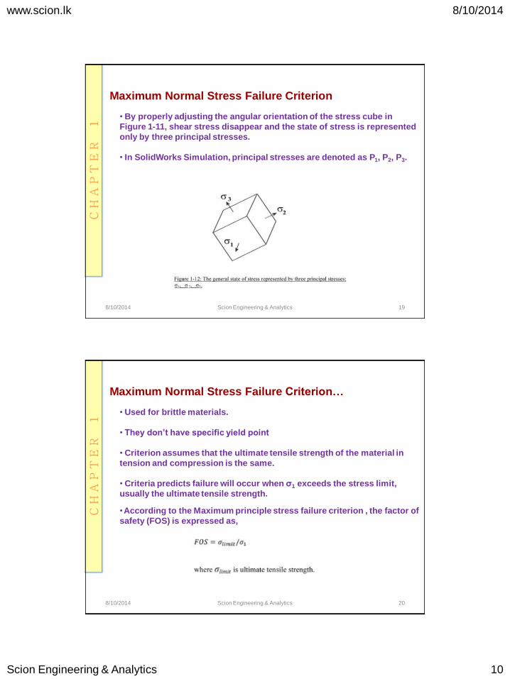
Maximum Normal Stress Failure Criterion
8/10/2014 19 Scion Engineering & Analytics
• By properly adjusting the angular orientation of the stress cube in
Figure 1-11, shear stress disappear and the state of stress is represented
only by three principal stresses.
• In SolidWorks Simulation, principal stresses are denoted as P1, P2, P3.
Maximum Normal Stress Failure Criterion…
8/10/2014 20 Scion Engineering & Analytics
• Used for brittle materials.
• They don’t have specific yield point
• Criterion assumes that the ultimate tensile strength of the material in
tension and compression is the same.
• Criteria predicts failure will occur when σ1 exceeds the stress limit,
usually the ultimate tensile strength.
• According to the Maximum principle stress failure criterion , the factor of