The information and the software discussed in this document are subject to change without notice and are not commitments by Dassault Systèmes SolidWorks Corporation (DS SolidWorks).No material may be reproduced or transmitted in any form or by any means, electronic or mechanical, for any purpose without the express written permission of DS SolidWorks.The software discussed in this document is furnished under a license and may be used or copied only in accordance with the terms of this license. All warranties given by DS SolidWorks as to the software and documentation are set forth in the SolidWorks Corporation License and Subscription Service Agreement, and nothing stated in, or implied by, this document or its contents shall be considered or deemed a modifica-tion or amendment of such warranties.
Patent Notices for SolidWorks Standard, Premium, Educational, and Professional ProductsU.S. Patents 5,815,154; 6,219,049; 6,219,055; 6,603,486; 6,611,725; 6,844,877; 6,898,560; 6,906,712; 7,079,990; 7,184,044; 7,477,262; 7,502,027; 7,558,705; 7,571,079; 7,590,497; 7,643,027; 7,672,822; 7,688,318; 7,694,238, and foreign patents, (e.g., EP 1,116,190 and JP 3,517,643). U.S. and foreign patents pending.
Trademarks and Other Notices for All SolidWorks ProductsSolidWorks, 3D PartStream.NET, 3D ContentCentral, PDMWorks, eDrawings, and the eDrawings logo are registered trademarks and FeatureManager is a jointly owned registered trademark of DS SolidWorks.SolidWorks Enterprise PDM, SolidWorks Simulation, SolidWorks Flow Simulation, and SolidWorks 2010 are product names of DS SolidWorks.CircuitWorks, Feature Palette, FloXpress, PhotoWorks, TolAnalyst, and XchangeWorks are trademarks of DS SolidWorks.FeatureWorks is a registered trademark of Geometric Ltd.Other brand or product names are trademarks or registered trademarks of their respective holders.COMMERCIAL COMPUTER SOFTWARE - PROPRIETARY U.S. Government Restricted Rights. Use, duplication, or disclosure by the government is subject to restrictions as set forth in FAR 52.227-19 (Commercial Computer Software - Restricted Rights), DFARS 227.7202 (Commercial Computer Software and Commercial Computer Software Documentation), and in the license agreement, as applicable.Contractor/Manufacturer:Dassault Systèmes SolidWorks Corporation, 300 Baker Avenue, Concord, Massachusetts 01742 USA
The Introduction to Stress Analysis Applications with SolidWorks Simulation and its supporting materials is designed to assist you in learning SolidWorks Simulation in an academic setting.
Online Tutorials
The Introduction to Stress Analysis Applications with SolidWorks Simulation is a companion resource and is supplemented by the SolidWorks Simulation Online Tutorials.
Accessing the Tutorials
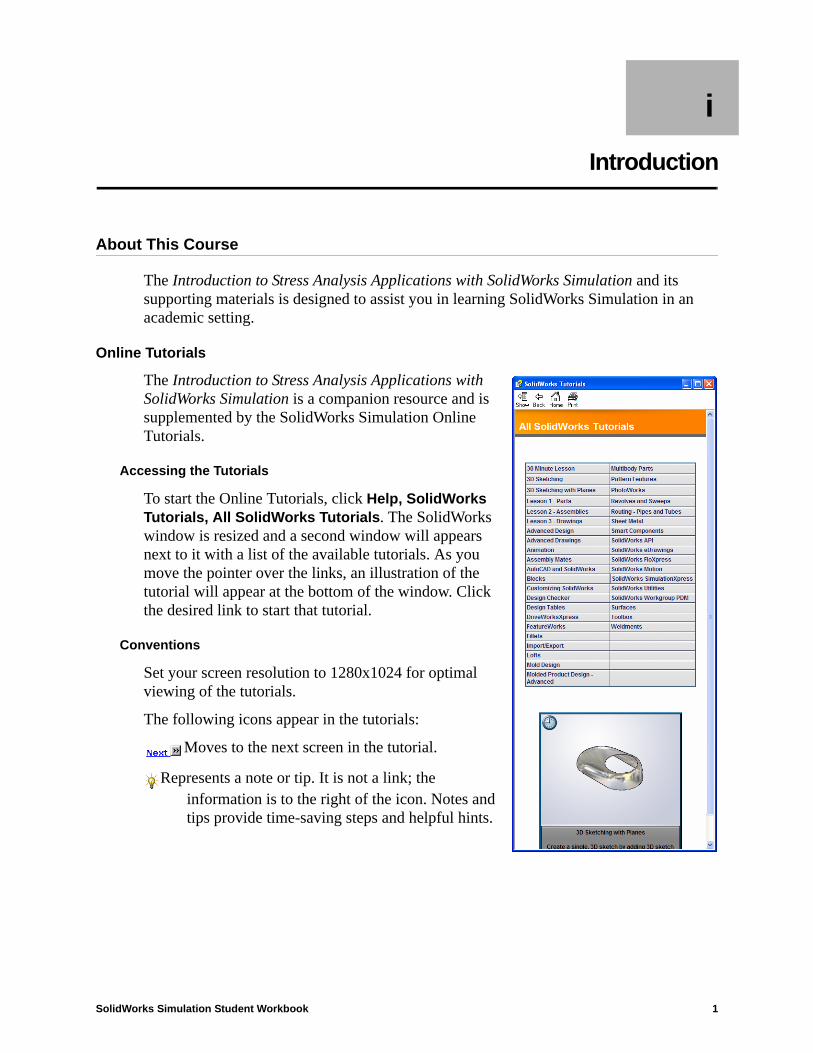
To start the Online Tutorials, click Help, SolidWorks Tutorials, All SolidWorks Tutorials. The SolidWorks window is resized and a second window will appears next to it with a list of the available tutorials. As you move the pointer over the links, an illustration of the tutorial will appear at the bottom of the window. Click the desired link to start that tutorial.
Conventions
Set your screen resolution to 1280x1024 for optimal viewing of the tutorials.
The following icons appear in the tutorials:
Moves to the next screen in the tutorial.
Represents a note or tip. It is not a link; the information is to the right of the icon. Notes and tips provide time-saving steps and helpful hints.
SolidWorks IntroductionEngineering Design and Technology Series
SolidWorks Simulation Student Workbook 2
You can click most toolbar buttons that appear in the lessons to flash the corresponding SolidWorks button.The first time you click the button, an ActiveX control message appears: An ActiveX control on this page might be unsafe to interact with other parts of the page. Do you want to allow this interaction? This is a standard precautionary measure. The ActiveX controls in the Online Tutorials will not harm your system. If you click No, the scripts are disabled for that topic. Click Yes to run the scripts and flash the button.
Open File or Set this option automatically opens the file or sets the option.
Video example shows a video about this step.
A closer look at... links to more information about a topic. Although not required to complete the tutorial, it offers more detail on the subject.
Why did I... links to more information about a procedure, and the reasons for the method given. This information is not required to complete the tutorial.
Printing the Tutorials
If you like, you can print the Online Tutorials by following this procedure:
1 On the tutorial navigation toolbar, click Show .
This displays the table of contents for the Online Tutorials.2 Right-click the book representing the lesson you wish to print and select Print from the
3 Select Print the selected heading and all subtopics, and click OK.4 Repeat this process for each lesson that you want to print.
SolidWorks Simulation Product Line
While this course focuses on the introduction to the rigid body dynamics using SolidWorks Motion Simulation, the full product line covers a wide range of analysis areas to consider. The paragraphs below lists the full offering of the SolidWorks Simulation packages and modules.
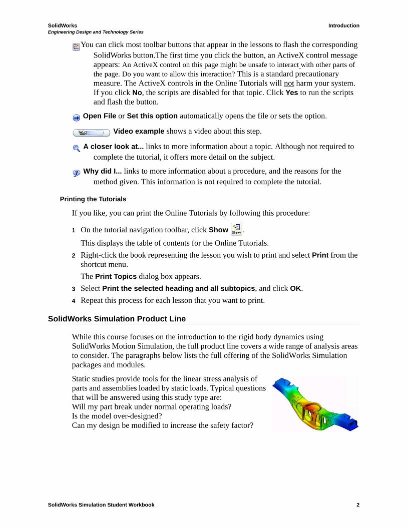
Static studies provide tools for the linear stress analysis of parts and assemblies loaded by static loads. Typical questions that will be answered using this study type are:Will my part break under normal operating loads?Is the model over-designed?Can my design be modified to increase the safety factor?
SolidWorks IntroductionEngineering Design and Technology Series
SolidWorks Simulation Student Workbook 3
Buckling studies analyze performance of the thin parts loaded in compression. Typical questions that will be answered using this study type are:Legs of my vessel are strong enough not to fail in yielding; but are they strong enough not to collapse due to loss of stability? Can my design be modified to ensure stability of the thin components in my assembly?
Frequency studies offer tools for the analysis of the natural modes and frequencies. This is essential in the design or many components loaded in both static and dynamic ways. Typical questions that will be answered using this study type are:Will my part resonate under normal operating loads?Are the frequency characteristics of my components suitable for the given application?Can my design be modified to improve the frequency characteristics?
Thermal studies offer tools for the analysis of the heat transfer by means of conduction, convection, and radiation. Typical questions that will be answered using this study type are:Will the temperatures changes effect my model?How does my model operate in an environment with temperature fluctuation?How long does it take for my model to cool down or overheat?Does temperature change cause my model to expand?Will the stresses caused by the temperature change cause my product failure (static studies, coupled with thermal studies would be used to answer this question)?
Drop test studies are used to analyze the stress of moving parts or assemblies impacting an obstacle. Typical questions that will be answered using this study type are:What will happen if my product is mishandled during transportation or dropped?How does my product behave when dropped on hard wood floor, carpet or concrete?
Optimization studies are applied to improve (optimize) your initial design based on a set of selected criteria such as maximum stress, weight, optimum frequency, etc. Typical questions that will be answered using this study type are:Can the shape of my model be changed while maintaining the design intent?Can my design be made lighter, smaller, cheaper without compromising strength of performance?
SolidWorks IntroductionEngineering Design and Technology Series
SolidWorks Simulation Student Workbook 4
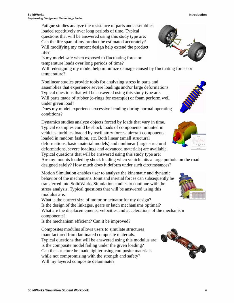
Fatigue studies analyze the resistance of parts and assemblies loaded repetitively over long periods of time. Typical questions that will be answered using this study type are:Can the life span of my product be estimated accurately?Will modifying my current design help extend the product life?Is my model safe when exposed to fluctuating force or temperature loads over long periods of time?Will redesigning my model help minimize damage caused by fluctuating forces or temperature?
Nonlinear studies provide tools for analyzing stress in parts and assemblies that experience severe loadings and/or large deformations. Typical questions that will be answered using this study type are:Will parts made of rubber (o-rings for example) or foam perform well under given load?Does my model experience excessive bending during normal operating conditions?
Dynamics studies analyze objects forced by loads that vary in time. Typical examples could be shock loads of components mounted in vehicles, turbines loaded by oscillatory forces, aircraft components loaded in random fashion, etc. Both linear (small structural deformations, basic material models) and nonlinear (large structural deformations, severe loadings and advanced materials) are available. Typical questions that will be answered using this study type are:Are my mounts loaded by shock loading when vehicle hits a large pothole on the road designed safely? How much does it deform under such circumstances?
Motion Simulation enables user to analyze the kinematic and dynamic behavior of the mechanisns. Joint and inertial forces can subsequently be transferred into SolidWorks Simulation studies to continue with the stress analysis. Typical questions that will be answered using this modulus are:What is the correct size of motor or actuator for my design?Is the design of the linkages, gears or latch mechanisms optimal?What are the displacemements, velocities and accelerations of the mechanism components?Is the mechanism efficient? Can it be improved?
Composites modulus allows users to simulate structures manufactured from laminated composite materials. Typical questions that will be answered using this modulus are:Is the composite model failing under the given loading?Can the structure be made lighter using composite materials while not compromising with the strength and safety?Will my layered composite delaminate?
SolidWorks Simulation Student Workbook 1-1
1 Lesson 1: Basic Functionality of SolidWorks Simulation
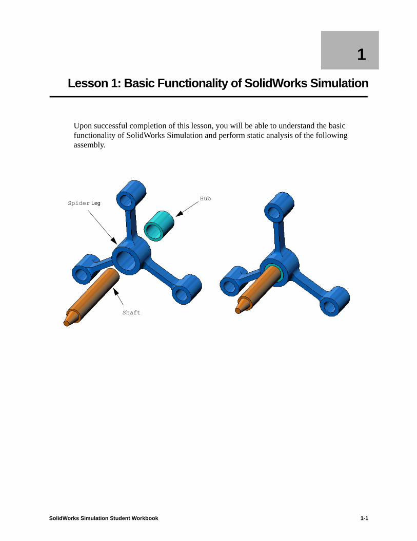
Upon successful completion of this lesson, you will be able to understand the basic functionality of SolidWorks Simulation and perform static analysis of the following assembly.
Shaft
Spider LegHub
Lesson 1: Basic Functionality of SolidWorks Simulation
1-2 SolidWorks Simulation Student Workbook
Active Learning Exercise — Performing Static Analysis
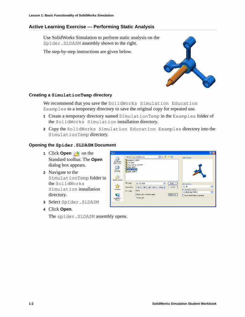
Use SolidWorks Simulation to perform static analysis on the Spider.SLDASM assembly shown to the right.
The step-by-step instructions are given below.
Creating a SimulationTemp directory
We recommend that you save the SolidWorks Simulation Education Examples to a temporary directory to save the original copy for repeated use.1 Create a temporary directory named SimulationTemp in the Examples folder of
the SolidWorks Simulation installation directory.2 Copy the SolidWorks Simulation Education Examples directory into the SimulationTemp directory.
Opening the Spider.SLDASM Document
1 Click Open on the Standard toolbar. The Open dialog box appears.
2 Navigate to the SimulationTemp folder in the SolidWorks Simulation installation directory.
3 Select Spider.SLDASM4 Click Open.
The spider.SLDASM assembly opens.
Lesson 1: Basic Functionality of SolidWorks Simulation
SolidWorks Simulation Student Workbook 1-3
The spider assembly has three components: the shaft, hub, and spider leg. The figure below shows the assembly components in exploded view.
Checking the SolidWorks Simulation Menu
If SolidWorks Simulation is properly installed, the SolidWorks Simulation menu appears on the SolidWorks menu bar. If not:1 Click Tools, Add-Ins.
The Add-Ins dialog box appears.2 Check the checkboxes next to SolidWorks Simulation.
If SolidWorks Simulation is not in the list, you need to install SolidWorks Simulation.3 Click OK.
The Simulation menu appears on the SolidWorks menu bar.
Shaft
Spider Leg
Hub
SolidWorks Simulation menu
Lesson 1: Basic Functionality of SolidWorks Simulation
1-4 SolidWorks Simulation Student Workbook
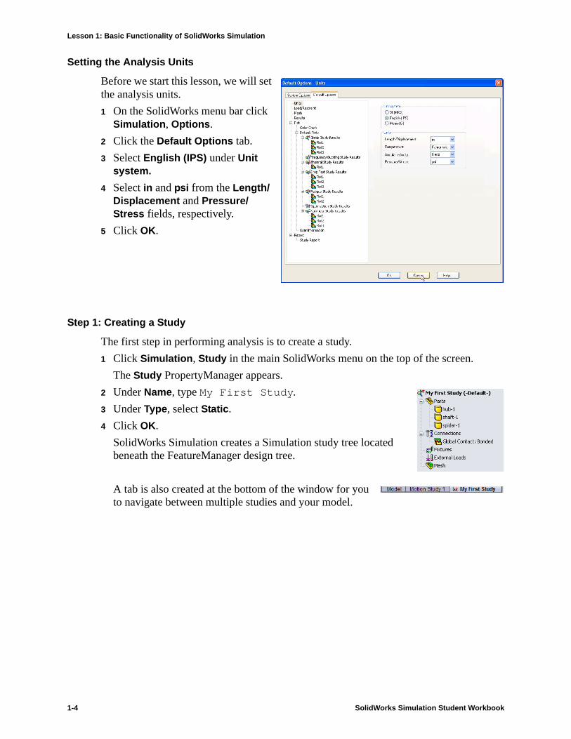
Setting the Analysis Units
Before we start this lesson, we will set the analysis units.1 On the SolidWorks menu bar click
Simulation, Options.2 Click the Default Options tab.3 Select English (IPS) under Unit
system.4 Select in and psi from the Length/
Displacement and Pressure/Stress fields, respectively.
5 Click OK.
Step 1: Creating a Study
The first step in performing analysis is to create a study.1 Click Simulation, Study in the main SolidWorks menu on the top of the screen.
The Study PropertyManager appears.2 Under Name, type My First Study.3 Under Type, select Static.4 Click OK.
SolidWorks Simulation creates a Simulation study tree located beneath the FeatureManager design tree.
A tab is also created at the bottom of the window for you to navigate between multiple studies and your model.
Lesson 1: Basic Functionality of SolidWorks Simulation
SolidWorks Simulation Student Workbook 1-5
Step 2: Assigning Material
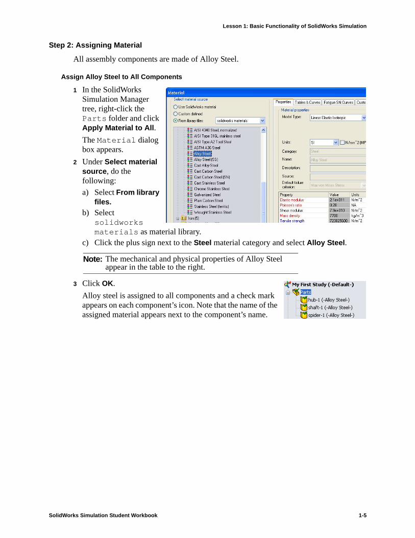
All assembly components are made of Alloy Steel.
Assign Alloy Steel to All Components
1 In the SolidWorks Simulation Manager tree, right-click the Parts folder and click Apply Material to All.The Material dialog box appears.
2 Under Select material source, do the following:a) Select From library
files.b) Select
solidworks materials as material library.
c) Click the plus sign next to the Steel material category and select Alloy Steel.
3 Click OK.Alloy steel is assigned to all components and a check mark appears on each component’s icon. Note that the name of the assigned material appears next to the component’s name.
Note: The mechanical and physical properties of Alloy Steel appear in the table to the right.
Lesson 1: Basic Functionality of SolidWorks Simulation
1-6 SolidWorks Simulation Student Workbook
Step 3: Applying Restraints
We will fix the three holes.1 Use the Arrow keys to rotate the assembly as shown in the figure.
2 In the Simulation study tree, right-click the Fixtures folder and click Fixed Geometry. The Fixture PropertyManager appears.
3 Make sure that Type is set to Fixed Geometry.4 In the graphics area, click the faces of the three holes, indicated in the figure below.Face<1>, Face<2>, and Face<3> appear in the Faces, Edges, Vertices for Fixture box.
5 Click . Fixed restraint is applied and its symbols appear on the selected faces.
Also, Fixture-1 item appears in the Fixtures folder in the Simulation study tree. The name of the restraint can be modified at any time.
Fixed restraint symbols
Lesson 1: Basic Functionality of SolidWorks Simulation
SolidWorks Simulation Student Workbook 1-7
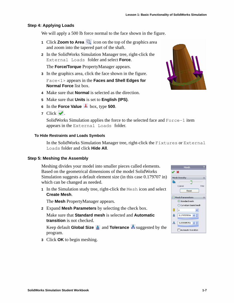
Step 4: Applying Loads
We will apply a 500 lb force normal to the face shown in the figure.
1 Click Zoom to Area icon on the top of the graphics area and zoom into the tapered part of the shaft.
2 In the SolidWorks Simulation Manager tree, right-click the External Loads folder and select Force.The Force/Torque PropertyManager appears.
3 In the graphics area, click the face shown in the figure.Face<1> appears in the Faces and Shell Edges for Normal Force list box.
4 Make sure that Normal is selected as the direction.5 Make sure that Units is set to English (IPS).6 In the Force Value box, type 500.7 Click .
SolidWorks Simulation applies the force to the selected face and Force-1 item appears in the External Loads folder.
To Hide Restraints and Loads Symbols
In the SolidWorks Simulation Manager tree, right-click the Fixtures or External Loads folder and click Hide All.
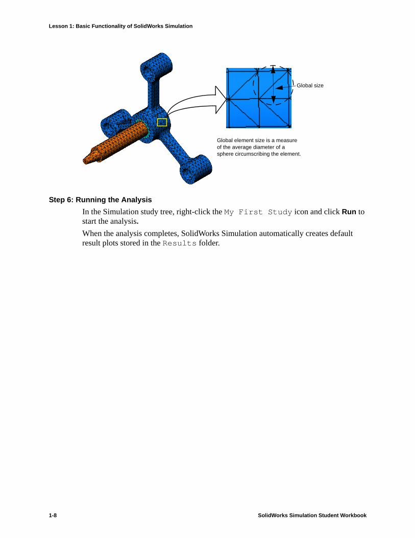
Step 5: Meshing the Assembly
Meshing divides your model into smaller pieces called elements. Based on the geometrical dimensions of the model SolidWorks Simulation suggests a default element size (in this case 0.179707 in) which can be changed as needed.1 In the Simulation study tree, right-click the Mesh icon and select
Create Mesh. The Mesh PropertyManager appears.
2 Expand Mesh Parameters by selecting the check box.Make sure that Standard mesh is selected and Automatic transition is not checked.Keep default Global Size and Tolerance suggested by the program.
3 Click OK to begin meshing.
Lesson 1: Basic Functionality of SolidWorks Simulation
1-8 SolidWorks Simulation Student Workbook
Step 6: Running the AnalysisIn the Simulation study tree, right-click the My First Study icon and click Run to start the analysis.When the analysis completes, SolidWorks Simulation automatically creates default result plots stored in the Results folder.
Global size
Global element size is a measure of the average diameter of a sphere circumscribing the element.
Lesson 1: Basic Functionality of SolidWorks Simulation
SolidWorks Simulation Student Workbook 1-9
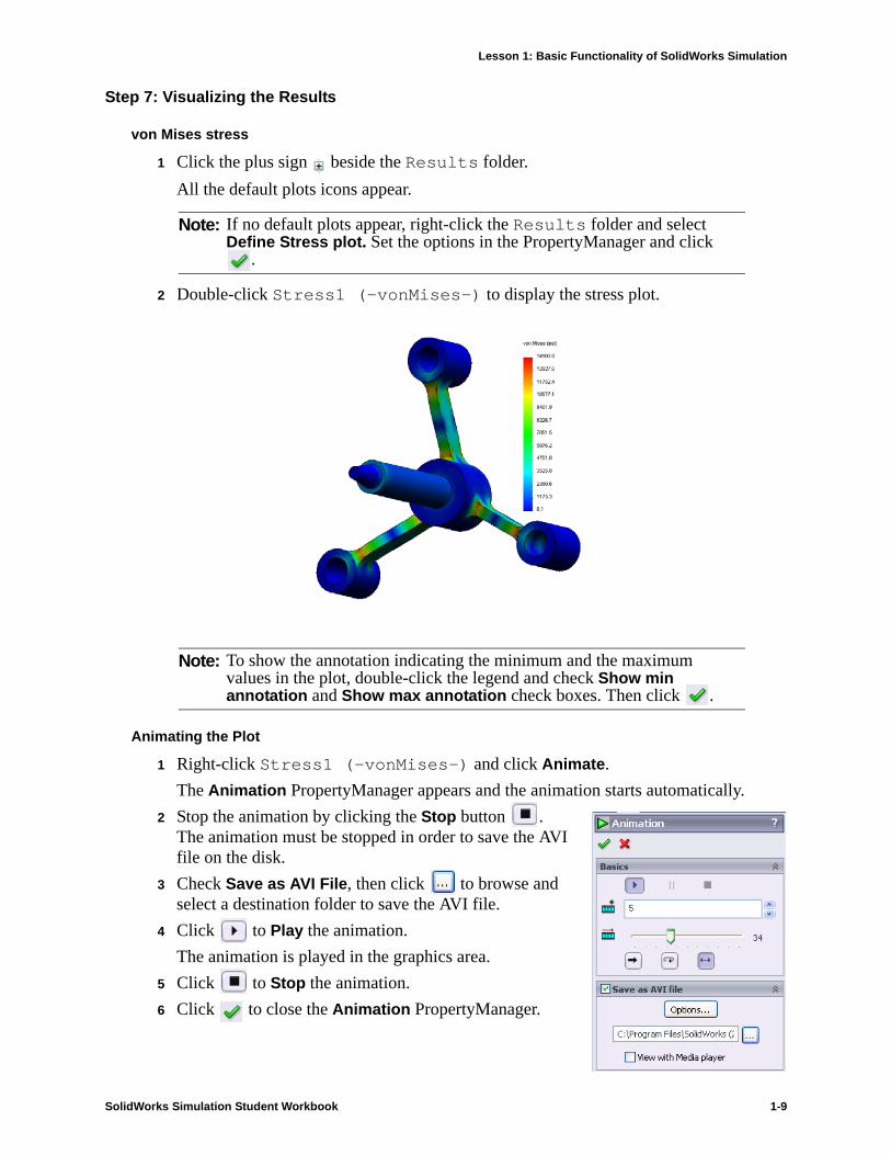
Step 7: Visualizing the Results
von Mises stress
1 Click the plus sign beside the Results folder.All the default plots icons appear.
2 Double-click Stress1 (-vonMises-) to display the stress plot.
Animating the Plot
1 Right-click Stress1 (-vonMises-) and click Animate. The Animation PropertyManager appears and the animation starts automatically.
2 Stop the animation by clicking the Stop button .The animation must be stopped in order to save the AVI file on the disk.
3 Check Save as AVI File, then click to browse and select a destination folder to save the AVI file.
4 Click to Play the animation.The animation is played in the graphics area.
5 Click to Stop the animation.6 Click to close the Animation PropertyManager.
Note: If no default plots appear, right-click the Results folder and select Define Stress plot. Set the options in the PropertyManager and click
.
Note: To show the annotation indicating the minimum and the maximum values in the plot, double-click the legend and check Show min annotation and Show max annotation check boxes. Then click .
Lesson 1: Basic Functionality of SolidWorks Simulation
1-10 SolidWorks Simulation Student Workbook
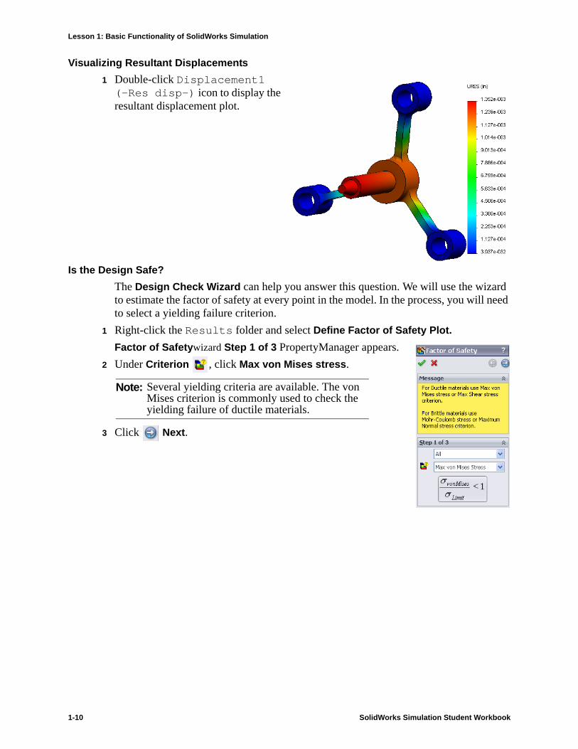
Visualizing Resultant Displacements1 Double-click Displacement1 (-Res disp-) icon to display the resultant displacement plot.
Is the Design Safe?The Design Check Wizard can help you answer this question. We will use the wizard to estimate the factor of safety at every point in the model. In the process, you will need to select a yielding failure criterion.
1 Right-click the Results folder and select Define Factor of Safety Plot. Factor of Safetywizard Step 1 of 3 PropertyManager appears.
2 Under Criterion , click Max von Mises stress.
3 Click Next.
Note: Several yielding criteria are available. The von Mises criterion is commonly used to check the yielding failure of ductile materials.
Lesson 1: Basic Functionality of SolidWorks Simulation
SolidWorks Simulation Student Workbook 1-11
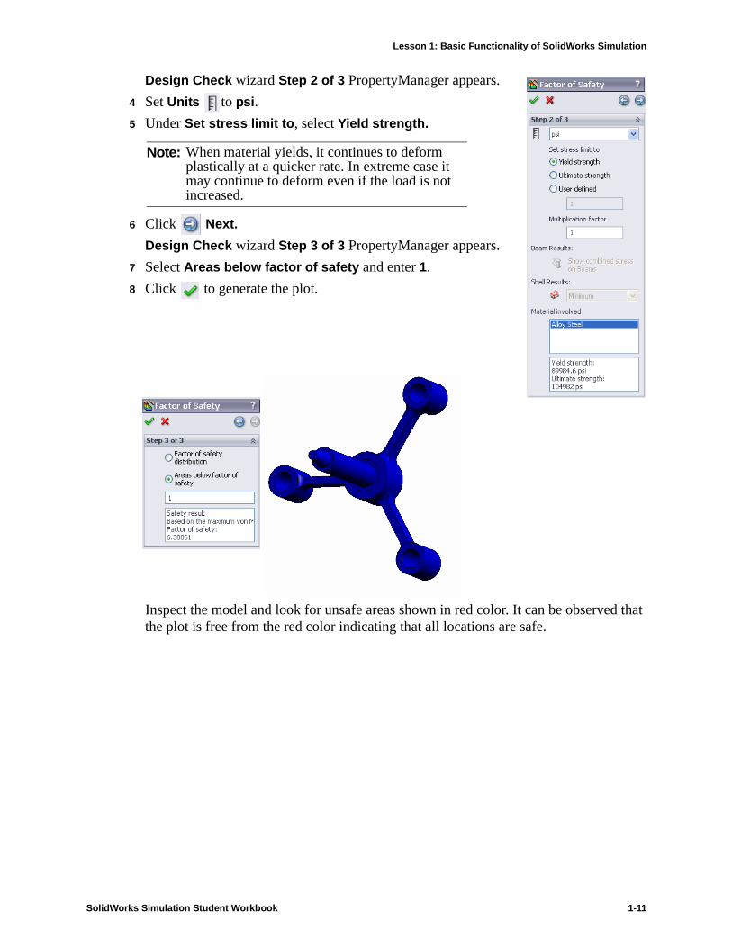
Design Check wizard Step 2 of 3 PropertyManager appears.4 Set Units to psi.5 Under Set stress limit to, select Yield strength.
7 Select Areas below factor of safety and enter 1.8 Click to generate the plot.
Inspect the model and look for unsafe areas shown in red color. It can be observed that the plot is free from the red color indicating that all locations are safe.
Note: When material yields, it continues to deform plastically at a quicker rate. In extreme case it may continue to deform even if the load is not increased.
Lesson 1: Basic Functionality of SolidWorks Simulation
1-12 SolidWorks Simulation Student Workbook
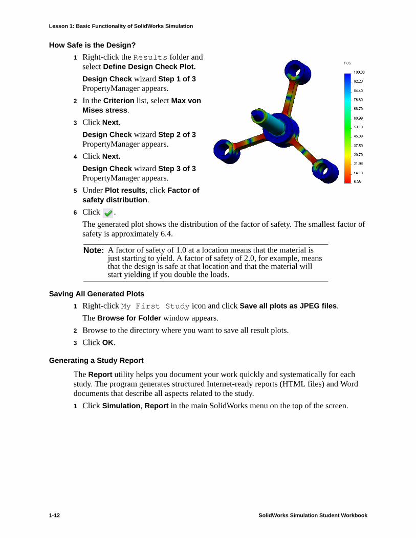
How Safe is the Design?1 Right-click the Results folder and
5 Under Plot results, click Factor of safety distribution.
6 Click . The generated plot shows the distribution of the factor of safety. The smallest factor of safety is approximately 6.4.
Saving All Generated Plots1 Right-click My First Study icon and click Save all plots as JPEG files.
The Browse for Folder window appears.2 Browse to the directory where you want to save all result plots.3 Click OK.
Generating a Study Report
The Report utility helps you document your work quickly and systematically for each study. The program generates structured Internet-ready reports (HTML files) and Word documents that describe all aspects related to the study.1 Click Simulation, Report in the main SolidWorks menu on the top of the screen.
Note: A factor of safety of 1.0 at a location means that the material is just starting to yield. A factor of safety of 2.0, for example, means that the design is safe at that location and that the material will start yielding if you double the loads.
Lesson 1: Basic Functionality of SolidWorks Simulation
SolidWorks Simulation Student Workbook 1-13
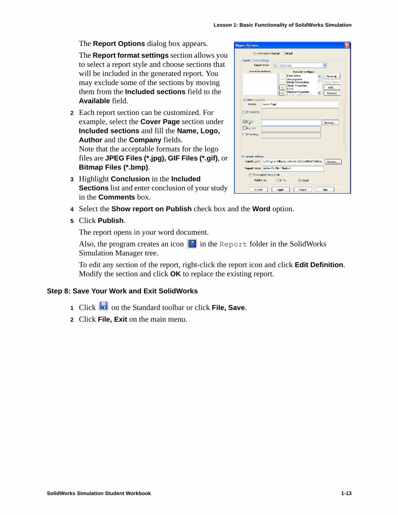
The Report Options dialog box appears.The Report format settings section allows you to select a report style and choose sections that will be included in the generated report. You may exclude some of the sections by moving them from the Included sections field to the Available field.
2 Each report section can be customized. For example, select the Cover Page section under Included sections and fill the Name, Logo, Author and the Company fields.Note that the acceptable formats for the logo files are JPEG Files (*.jpg), GIF Files (*.gif), or Bitmap Files (*.bmp).
3 Highlight Conclusion in the Included Sections list and enter conclusion of your study in the Comments box.
4 Select the Show report on Publish check box and the Word option.5 Click Publish.
The report opens in your word document.Also, the program creates an icon in the Report folder in the SolidWorks Simulation Manager tree.To edit any section of the report, right-click the report icon and click Edit Definition. Modify the section and click OK to replace the existing report.
Step 8: Save Your Work and Exit SolidWorks
1 Click on the Standard toolbar or click File, Save.2 Click File, Exit on the main menu.
Lesson 1: Basic Functionality of SolidWorks Simulation
1-14 SolidWorks Simulation Student Workbook
5 Minute Assessment
1 How do you start a SolidWorks Simulation session?__________________________________________________________________________________________________________________________________________
2 What do you do if SolidWorks Simulation menu is not on the SolidWorks menu bar?__________________________________________________________________________________________________________________________________________
3 What types of documents can SolidWorks Simulation analyze? ____________________________________________________________________________________________________________
4 What is analysis? _____________________________________________________________________________________________________________________________
5 Why is analysis important?_____________________________________________________________________________________________________________________
6 What is an analysis study? _____________________________________________________________________________________________________________________
7 What types of analysis can be perfomed in SolidWorks Simulation? ____________________________________________________________________________________
8 What does static analysis calculate?______________________________________________________________________________________________________________
9 What is stress?______________________________________________________________________________________________________________________________
10 What are the main steps in performing analysis?____________________________________________________________________________________________________
11 How can you change the material of a part? _______________________________________________________________________________________________________
12 The Design Check wizard shows a factor of safety of 0.8 at some locations. Is your design safe? _______________________________________________________________________________________________________________________________
Lesson 1: Basic Functionality of SolidWorks Simulation
SolidWorks Simulation Student Workbook 1-15
Projects — Deflection of a Beam Due to an End Force
Some simple problems have exact answers. One of these problems is a beam loaded by force at its tip as shown in the figure. We will use SolidWorks Simulation to solve this problem and compare its results with the exact solution.
Tasks1 Open the Front_Cantilever.sldprt file located in the Examples folder of the SolidWorks Simulation installation directory.
2 Measure the width, height, and length of the cantilever.
3 Save the part to another name.4 Create a Static study.5 Assign Alloy Steel to the part. What is the
value of the elastic modulus in psi?Answer:___________________________
6 Fix one of the end faces of the cantilever.7 Apply a downward force to the upper edge
of the other end face with magnitude of 100 lb.
8 Mesh the part and run the analysis. 9 Plot the displacement in the Y-direction. What is the maximum Y-displacement at the
free end of the cantilever?Answer: _______________________________
10 Calculate the theoretical vertical displacement at the free end using the following formula:
where F is the force, L is the length of the beam, E is the modulus of elasticity, w and h are the width and height of the beam, respectively.Answer: _____________________________________________________________________
11 Calculate the error in the vertical displacement using the following formula:
1 The sequence of creating a model in SolidWorks, manufacturing a prototype, and testing it: ________________
2 A what-if scenario of analysis type, materials, restraints, and loads: _________3 The method that SolidWorks Simulation uses to perform analysis: ______________4 The type of study that calculates displacements, strains, and stresses: ___________5 The process of subdividing the model into small pieces: __________6 Small pieces of simple shapes created during meshing: ___________7 Elements share common points called: _________8 The force acting on an area divided by that area: __________9 The sudden collapse of slender designs due to axial compressive loads: _________10 A study that calculates how hot a design gets: ____________11 A number that provides a general description of the state of stress: ______________12 Normal stresses on planes where shear stresses vanish: _________________13 The frequencies that a body tends to vibrate in: _____________________14 The type of analysis that can help you avoid resonance: __________________
Lesson 1: Basic Functionality of SolidWorks Simulation
Directions: Answer each question by writing the correct answer or answers in the space provided.
1 You test your design by creating a study. What is a study? ____________________________________________________________________________________________
2 What types of analyses can you perform in SolidWorks Simulation? ___________________________________________________________________________________
3 After obtaining the results of a study, you changed the material, loads, and/or restraints. Do you have to mesh again?___________________________________________________________________________________________________________________
4 After meshing a study, you changed the geometry. Do you need to mesh the model again? _____________________________________________________________________________________________________________________________________
5 How do you create a new static study? ___________________________________________________________________________________________________________
6 What is a mesh? _____________________________________________________________________________________________________________________________
7 In an assembly, how many icons you expect to see in the Solids folder? _________________________________________________________________________________
Lesson 1: Basic Functionality of SolidWorks Simulation
1-18 SolidWorks Simulation Student Workbook
Lesson 2: Adaptive Methods in SolidWorks Simulation
SolidWorks Simulation Student Workbook 2-19
2 Lesson 2: Adaptive Methods in SolidWorks Simulation
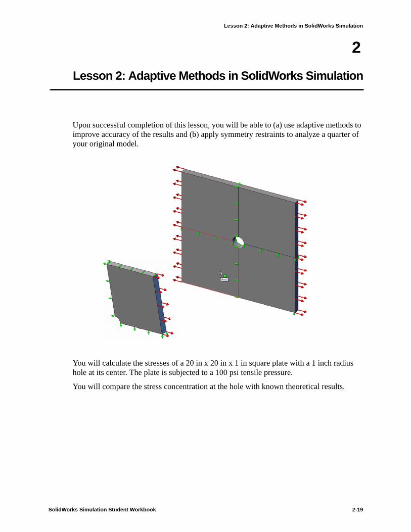
Upon successful completion of this lesson, you will be able to (a) use adaptive methods to improve accuracy of the results and (b) apply symmetry restraints to analyze a quarter of your original model.
You will calculate the stresses of a 20 in x 20 in x 1 in square plate with a 1 inch radius hole at its center. The plate is subjected to a 100 psi tensile pressure.
You will compare the stress concentration at the hole with known theoretical results.
Lesson 2: Adaptive Methods in SolidWorks Simulation
2-20 SolidWorks Simulation Student Workbook
Active Learning Exercise — Part 1
Use SolidWorks Simulation to perform static analysis on the Plate-with-hole.SLDPRT part shown to the right.
You will calculate the stresses of a 20 in x 20 in x 1 in square plate with a 1 inch radius hole at its center. The plate is subjected to a 100 psi tensile pressure.
You will compare the stress concentration at the hole with known theoretical results.
The step-by-step instructions are given below.
Creating Simulationtemp directory
We recommend that you save the SolidWorks Simulation Education Examples to a temporary directory to save the original copy for repeated use.1 Create a temporary directory named Simulationtemp in the Examples folder of
the SolidWorks Simulation installation directory.2 Copy the SolidWorks Simulation Education Examples directory into the Simulationtemp directory.
Opening the Plate-with-hole.SLDPRT Document
1 Click Open on the Standard toolbar. The Open dialog box appears.2 Navigate to the Simulationtemp folder in the SolidWorks Simulation installation
The Plate-with-hole.SLDPRT part opens.Notice that the part has two configurations: (a) Quarter plate, and (b) Whole plate. Make sure that Whole plate configuration is active.
Checking the SolidWorks Simulation Menu
If SolidWorks Simulation is added-in, the SolidWorks Simulation menu appears on the SolidWorks menu bar. If not:1 Click Tools, Add-Ins.
The Add-Ins dialog box appears.2 Check the checkboxes next to SolidWorks Simulation.
If SolidWorks Simulation is not in the list, you need to install SolidWorks Simulation.3 Click OK.
Note: The configurations of the document are listed under the ConfigurationManager tab at the top of the left pane.
SolidWorks Simulation menu
Lesson 2: Adaptive Methods in SolidWorks Simulation
SolidWorks Simulation Student Workbook 2-21
The SolidWorks Simulation menu appears on the SolidWorks menu bar.
Setting the Analysis Units
Before we start this lesson, we will set the analysis units.1 Click Simulation, Options.2 Click the Default Options tab.3 Select English (IPS) in Unit system and in and psi as the units for the length and
stress, respectively.4 Click .
Step 1: Creating a Study
The first step in performing analysis is to create a study.1 Click Simulation, Study in the main SolidWorks menu on the top of the screen.
The Study PropertyManager appears.2 Under Name, type Whole plate.3 Under Type, select Static.4 Click .
SolidWorks Simulation creates a Simulation study tree located beneath the FeatureManager design tree.
Step 2: Assigning Material
Assign Alloy Steel
1 In the SolidWorks Simulation Manager tree, right-click the Plate-with-hole folder and click Apply Material to All.The Material dialog box appears.
2 Under Select material source, do the following:a) Select From library
files.b) Select
solidworks materials as material library.c) Click the plus sign next to the Steel material category and select Alloy Steel.
3 Click OK.
Note: The mechanical and physical properties of Alloy Steel appear in the table to the right.
Lesson 2: Adaptive Methods in SolidWorks Simulation
2-22 SolidWorks Simulation Student Workbook
Step 3: Applying Restraints
You apply restraints to prevent the out of plane rotations and free body motions.1 Press spacebar and select *Trimetric in the
Orientation menu. The model orientation is as shown in the figure.
2 In the Simulation study tree, right-click the Fixtures folder and click Advanced Fixtures. The Fixture PropertyManager appears.
3 Make sure that Type is set to Use Reference Geometry.
4 In the graphics area, select the 8 edges shown in the figure.Edge<1> through Edge<8> appear in the Faces, Edges, Vertices for Restraint box.
5 Click in the Face, Edge, Plane, Axis for Direction box and select Plane1 from the flyout FeatureManager tree.
6 Under Translations, select Along plane Dir 2 .7 Click .
The restraints are applied and their symbols appear on the selected edges. Also, a restraint icon (Fixture-1) appears in the Fixtures folder.
Similarly, you follow steps 2 to 7 to apply restraints to the vertical set of edges as shown in the figure to restrain the 8 edges Along plane Dir 1
of Plane1.
To prevent displacement of the model in the global Z-direction, a restraint on the vertex shown in the figure below must be defined.
Lesson 2: Adaptive Methods in SolidWorks Simulation
SolidWorks Simulation Student Workbook 2-23
1 In the SolidWorks Simulation Manager tree, right-click the Fixtures folder and click Advanced Fixtures. The Fixture PropertyManager appears.
2 Make sure that Type is set to Use reference geometry.
3 In the graphics area, click the vertex shown in the figure.Vertex<1> appears in the Faces, Edges, Vertices for Restraint box.
4 Click in the Face, Edge, Plane, Axis for Direction box and select Plane1 from the flyout FeatureManager tree.
5 Under Translations, select Normal to Plane . 6 Click .
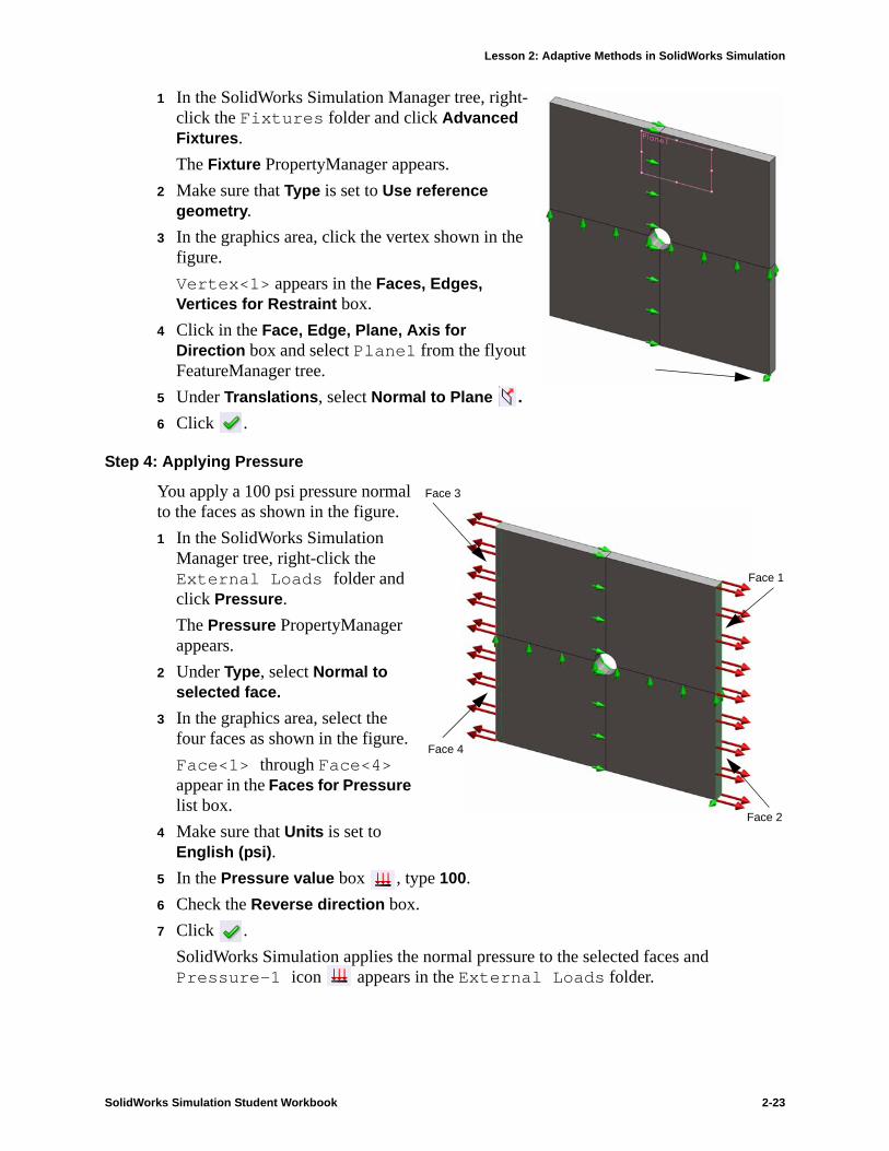
Step 4: Applying Pressure
You apply a 100 psi pressure normal to the faces as shown in the figure.1 In the SolidWorks Simulation
Manager tree, right-click the External Loads folder and click Pressure.The Pressure PropertyManager appears.
2 Under Type, select Normal to selected face.
3 In the graphics area, select the four faces as shown in the figure.Face<1> through Face<4> appear in the Faces for Pressure list box.
4 Make sure that Units is set to English (psi).
5 In the Pressure value box , type 100.6 Check the Reverse direction box.7 Click .
SolidWorks Simulation applies the normal pressure to the selected faces and Pressure-1 icon appears in the External Loads folder.
Face 3
Face 4
Face 1
Face 2
Lesson 2: Adaptive Methods in SolidWorks Simulation
2-24 SolidWorks Simulation Student Workbook
To Hide Restraints and Loads Symbols
In the SolidWorks Simulation Manager tree, right-click the Fixtures or External Loads folder and click Hide All.
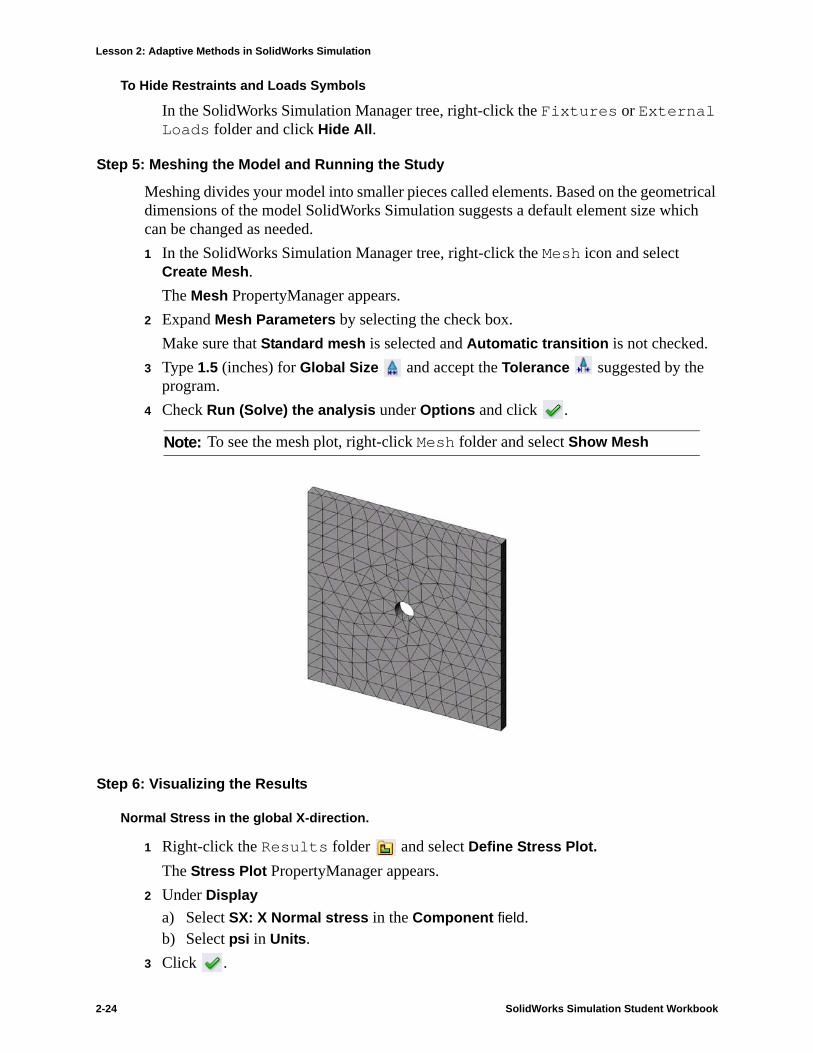
Step 5: Meshing the Model and Running the Study
Meshing divides your model into smaller pieces called elements. Based on the geometrical dimensions of the model SolidWorks Simulation suggests a default element size which can be changed as needed.1 In the SolidWorks Simulation Manager tree, right-click the Mesh icon and select
Create Mesh. The Mesh PropertyManager appears.
2 Expand Mesh Parameters by selecting the check box.Make sure that Standard mesh is selected and Automatic transition is not checked.
3 Type 1.5 (inches) for Global Size and accept the Tolerance suggested by the program.
4 Check Run (Solve) the analysis under Options and click .
Step 6: Visualizing the Results
Normal Stress in the global X-direction.
1 Right-click the Results folder and select Define Stress Plot.The Stress Plot PropertyManager appears.
2 Under Displaya) Select SX: X Normal stress in the Component field.b) Select psi in Units.
3 Click .
Note: To see the mesh plot, right-click Mesh folder and select Show Mesh
Lesson 2: Adaptive Methods in SolidWorks Simulation
SolidWorks Simulation Student Workbook 2-25
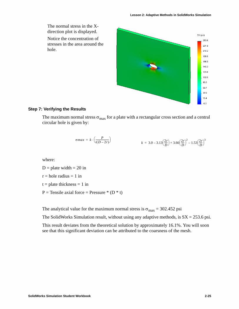
The normal stress in the X-direction plot is displayed.Notice the concentration of stresses in the area around the hole.
Step 7: Verifying the Results
The maximum normal stress σmax for a plate with a rectangular cross section and a central circular hole is given by:
where:
D = plate width = 20 in
r = hole radius = 1 in
t = plate thickness = 1 in
P = Tensile axial force = Pressure * (D * t)
The analytical value for the maximum normal stress is σmax = 302.452 psi
The SolidWorks Simulation result, without using any adaptive methods, is SX = 253.6 psi.
This result deviates from the theoretical solution by approximately 16.1%. You will soon see that this significant deviation can be attributed to the coarsness of the mesh.
σmax k Pt D 2r–( )----------------------⎝ ⎠⎛ ⎞⋅=
k 3.0 3.13 2rD-----⎝ ⎠⎛ ⎞– 3.66 2r
D-----⎝ ⎠⎛ ⎞ 2
1.53 2rD-----⎝ ⎠⎛ ⎞ 3
–+=
Lesson 2: Adaptive Methods in SolidWorks Simulation
2-26 SolidWorks Simulation Student Workbook
Active Learning Exercise — Part 2
In the second part of the exercise you will model a quarter of the plate with help of the symmetry restraints.
Step 1: Activate New Configuration
1 Click the ConfigurationManager tab .
2 In the Configuration Manager tree double-click the Quarter plate icon.The Quarter plate configuration will be activated.
3 The model of the quarter plate appears in the graphics area.
.
Step 2: Creating a Study
The new study that you create is based on the active Quarter plate configuration.1 Click Simulation, Study in the main SolidWorks menu on the top of the screen.
The Study PropertyManager appears.2 Under Name, type Quarter plate.3 Under Type, select Static.4 Click .
SolidWorks Simulation creates a representative tree for the study located in a tab at the bottom of the screen.
Step 3: Assigning Material
Follow the procedure described in Step 2 of Part 1 to assign Alloy Steel material.
Note: The symmetry restraints can be used to analyze a portion of the model only. This approach can considerably save the analysis time, particularly if you are dealing with large models.Symmetry conditions require that geometry, loads, material properties and restraints are equal across the plane of symmetry.
Note: To access a study associated with an inactive configuration right-click its icon and select Activate SW configuration.
Lesson 2: Adaptive Methods in SolidWorks Simulation
SolidWorks Simulation Student Workbook 2-27
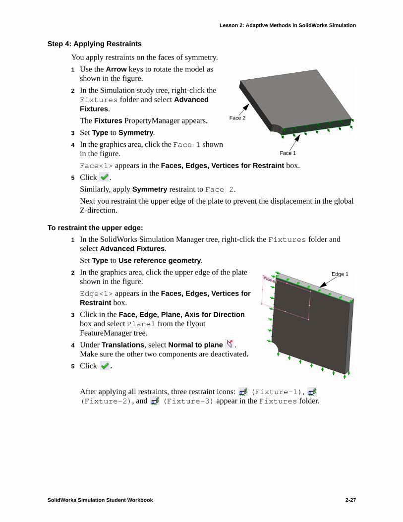
Step 4: Applying Restraints
You apply restraints on the faces of symmetry.1 Use the Arrow keys to rotate the model as
shown in the figure.2 In the Simulation study tree, right-click the Fixtures folder and select Advanced Fixtures. The Fixtures PropertyManager appears.
3 Set Type to Symmetry.4 In the graphics area, click the Face 1 shown
in the figure.Face<1> appears in the Faces, Edges, Vertices for Restraint box.
5 Click . Similarly, apply Symmetry restraint to Face 2. Next you restraint the upper edge of the plate to prevent the displacement in the global Z-direction.
To restraint the upper edge:1 In the SolidWorks Simulation Manager tree, right-click the Fixtures folder and
select Advanced Fixtures.Set Type to Use reference geometry.
2 In the graphics area, click the upper edge of the plate shown in the figure.Edge<1> appears in the Faces, Edges, Vertices for Restraint box.
3 Click in the Face, Edge, Plane, Axis for Direction box and select Plane1 from the flyout FeatureManager tree.
4 Under Translations, select Normal to plane . Make sure the other two components are deactivated.
5 Click .
After applying all restraints, three restraint icons: (Fixture-1), (Fixture-2), and (Fixture-3) appear in the Fixtures folder.
Face 1
Face 2
Edge 1
Lesson 2: Adaptive Methods in SolidWorks Simulation
2-28 SolidWorks Simulation Student Workbook
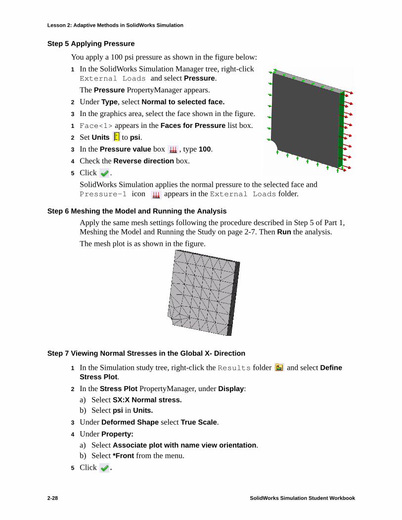
Step 5 Applying Pressure
You apply a 100 psi pressure as shown in the figure below:1 In the SolidWorks Simulation Manager tree, right-click External Loads and select Pressure.The Pressure PropertyManager appears.
2 Under Type, select Normal to selected face.3 In the graphics area, select the face shown in the figure. 1 Face<1> appears in the Faces for Pressure list box.2 Set Units to psi.3 In the Pressure value box , type 100.4 Check the Reverse direction box.5 Click .
SolidWorks Simulation applies the normal pressure to the selected face and Pressure-1 icon appears in the External Loads folder.
Step 6 Meshing the Model and Running the AnalysisApply the same mesh settings following the procedure described in Step 5 of Part 1, Meshing the Model and Running the Study on page 2-7. Then Run the analysis.The mesh plot is as shown in the figure.
Step 7 Viewing Normal Stresses in the Global X- Direction
1 In the Simulation study tree, right-click the Results folder and select Define Stress Plot.
2 In the Stress Plot PropertyManager, under Display:a) Select SX:X Normal stress.b) Select psi in Units.
3 Under Deformed Shape select True Scale.4 Under Property:
a) Select Associate plot with name view orientation.b) Select *Front from the menu.
5 Click .
Lesson 2: Adaptive Methods in SolidWorks Simulation
SolidWorks Simulation Student Workbook 2-29
The normal stress in the X-direction is displayed on the real deformed shape of the plate.
Step 8 Verifying the Results
For the quarter model, the maximum normal SX stress is 269.6 psi. This result is comparable to the results for the whole plate.
This result deviates from the theoretical solution by approximately 10.8%. As was mentioned in the conclusion of Part 1 of this lesson, you will see that this deviation can be attributed to the coarsness of the computational mesh. You can improve the accuracy by using a smaller element size manually or by using automatic adaptive methods.
In Part 3 you will use the h-adaptive method to improve the accuracy.
Lesson 2: Adaptive Methods in SolidWorks Simulation
2-30 SolidWorks Simulation Student Workbook
Active Learning Exercise — Part 3
In the third part of the exercise you will apply the h-adaptive method to solve the same problem for the Quarter plate configuration.
To demonstrate the power of the h-adaptive method, first, you will mesh the model with a large element size, and then you will observe how the h-method changes the mesh size to improve the accuracy of the results.
Step 1 Defining a New Study
You will create a new study by duplicating the previous study.1 Right-click the Quarter plate study at the bottom of the
screen and select Duplicate.
The Define Study Name dialog box appears. 2 In the Study Name box, type H-adaptive.3 Under Configuration to use: select Quarter plate.4 Click OK.
Step 2 Setting the h-adaptive Parameters1 In the Simulation study tree, right-click H-adaptive
and select Properties.2 In the dialog box, in the Options tab, select FFEPlus under Solver.3 In the Adaptive tab, under Adaptive method, select h-adaptive.4 Under h-Adaptive options, do the following:
a) Move the Target accuracy slider to 99%.b) Set Maximum no. of loops to 5.c) Check Mesh coarsening.
5 Click OK.
Note: By duplicating the study, all the folders of the original study are copied to the new study. As long as the properties of the new study remain the same, you do not need to redefine material properties, loads, restraints, etc.
Lesson 2: Adaptive Methods in SolidWorks Simulation
SolidWorks Simulation Student Workbook 2-31
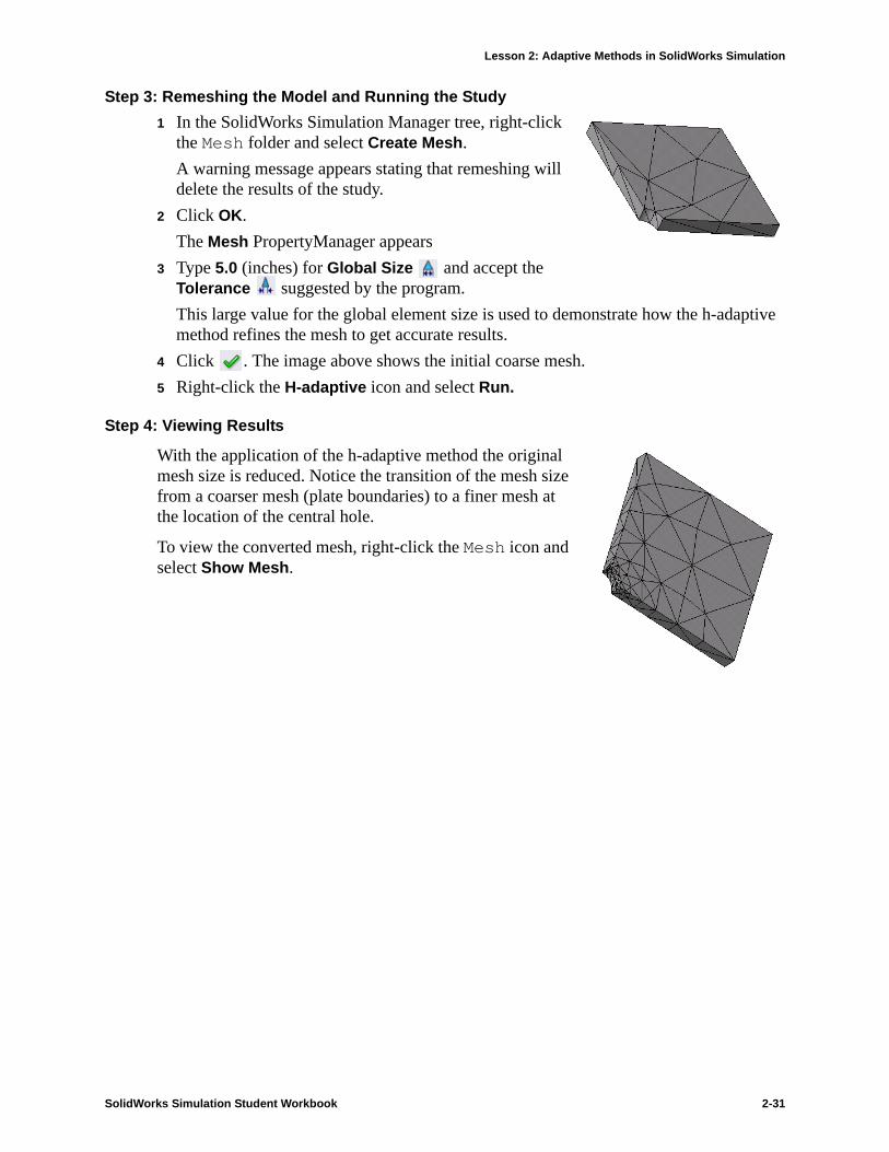
Step 3: Remeshing the Model and Running the Study1 In the SolidWorks Simulation Manager tree, right-click
the Mesh folder and select Create Mesh.A warning message appears stating that remeshing will delete the results of the study.
2 Click OK.The Mesh PropertyManager appears
3 Type 5.0 (inches) for Global Size and accept the Tolerance suggested by the program.This large value for the global element size is used to demonstrate how the h-adaptive method refines the mesh to get accurate results.
4 Click . The image above shows the initial coarse mesh.5 Right-click the H-adaptive icon and select Run.
Step 4: Viewing Results
With the application of the h-adaptive method the original mesh size is reduced. Notice the transition of the mesh size from a coarser mesh (plate boundaries) to a finer mesh at the location of the central hole.
To view the converted mesh, right-click the Mesh icon and select Show Mesh.
Lesson 2: Adaptive Methods in SolidWorks Simulation
2-32 SolidWorks Simulation Student Workbook
View normal stress in the global X-direction
In the SolidWorks Simulation Manager tree, double-click the Stress2 (X-normal) plot in the Results folder .
The analytical value for the maximum normal stress is σmax= 302.452 psi.
The SolidWorks Simulation result with the application of the h-adaptive method is SX = 322.4 psi, which is closer to the analytical solution (approximate error: 6.6%).
Note: The desired accuracy set in the study properties (in your case 99%) does not mean that the resulting stresses will be within the maximum error of 1%. In finite element method measures other than stresses are used to evaluate the accuracy of the solution. However, it can be concluded that as the adaptive algorithm refines the mesh, the stress solution becomes more accurate.
Lesson 2: Adaptive Methods in SolidWorks Simulation
SolidWorks Simulation Student Workbook 2-33
Step 9 Viewing Convergence Graphs
1 In the Simulation study tree , right-click the Results folder and select Define Adaptive Convergence Graph.
2 In the PropertyManager, check all options and click .The convergence graph of all checked quantities is displayed.
Note: To further improve the accuracy of the solution, it is possible to continue with the h-adaptivity iterations by initiating subsequent study runs. Each subsequent study run uses the final mesh from the last iteration of the previous run as the initial mesh for the new run. To try this Run the H-adaptive study again.
Lesson 2: Adaptive Methods in SolidWorks Simulation
2-34 SolidWorks Simulation Student Workbook
5 Minute Assessment
1 If you modify material, loads or restraints, the results get invalidated while the mesh does not, why?______________________________________________________________________________________________________________________________________
2 Does changing a dimension invalidate the current mesh? ______________________________________________________________________________________________________________________________________________________________
3 How do you activate a configuration? _____________________________________________________________________________________________________________________________________________________________________________
4 What is a rigid body motion?______________________________________________ ____________________________________________________________________________________________________________________________________
5 What is the h-adaptive method and for what study type can it be used? _____________________________________________________________________________________________________________________________________________________
6 What is the advantage of using h-adaptive to improve the accuracy compared to using mesh control? ________________________________________________________________________________________________________________________________________
7 Does the number of elements change in iterations of the p-adaptive method?______________________________________________________________________________________________________________________________________
Lesson 2: Adaptive Methods in SolidWorks Simulation
SolidWorks Simulation Student Workbook 2-35
Projects — Modeling the Quarter Plate with a Shell Mesh
Use shell mesh to solve the quarter plate model. You will apply mesh control to improve the accuracy of the results.
Tasks1 Click Insert, Surface, Mid Surface in the main SolidWorks menu on the top of the
screen.2 Select the front and back surfaces of the plate as
shown.3 Click OK.4 Create a Static study.5 Expand the Plate-with-hole folder, right-click
the SolidBody and select Exclude from Analysis.6 In the FeatureManager design tree, expand the Solid Bodies folder and hide the existing solid body.
7 Define 1 in (Thin formulation) shell. To do this:a) Right-click the SurfaceBody in the Plate-
with-hole folder of the Simulation study tree and select Edit Definition.
b) In the Shell Definition PropertyManager, select in and type 1 in for Shell thickness.
c) Click .8 Assign Alloy Steel to the shell. To do this:
a) Right-click the Plate-with-hole folder and select Apply Material to All.b) Select From library files and select the Alloy Steel material.c) Click .
9 Apply symmetry restraints to the two edges shown in the figure.
a) Right-click the Fixtures folder and select Advanced Fixtures.b) In the Faces, Edges, Vertices for Restraint field
select the edge indicated in the figure.c) In the Face, Edge, Plane, Axis for Direction field
select Plane3.d) Restraint the Normal to Plane translation and Along
Plane Dir 1 and Along Plane Dir 2 rotations.e) Click .
Note: For a shell mesh, it is sufficient to restrain one edge instead of the face.
Lesson 2: Adaptive Methods in SolidWorks Simulation
2-36 SolidWorks Simulation Student Workbook
10 Using the identical procedure apply a symmetry restraint to the other edge shown in the figure. This time use Plane2 feature for Face, Edge, Plane, Axis for Direction field.
11 Apply 100 psi Pressure to the edge shown in the figure.a) Right-click the External Loads folder and select
Pressure.b) Under Type select Use reference geometry.c) In the Faces, Edges for Pressure field select the
vertical edge shown in the figure.d) In the Face, Edge, Plane, Axis for Direction field
select the edge indicated in the figure.e) Specify 100 psi in the Pressure Value dialog.f) Click .
12 Apply mesh control to the edge shown in the figure.Using a smaller element size improves the accuracy.
13 Mesh the part and run the analysis.14 Plot the stress in the X-direction. What is the maximum SX stress?
Answer: _______________________________15 Calculate the error in the normal SX stress using the following formula:
1 A method that improves stress results by refining the mesh automatically in regions of stress concentration: _____________________________________________________________________
2 A method that improves stress results by increasing the polynomial order: _____________________________________________________________________
3 The type of degrees of freedom that a node of a tetrahedral element has: _____________________________________________________________________
4 The types of degrees of freedom that a node of a shell element has: _____________________________________________________________________
5 A material with equal elastic properties in all directions: _____________________________________________________________________
6 The mesh type appropriate for bulky models: _____________________________________________________________________
7 The mesh type appropriate for thin models: _____________________________________________________________________
8 The mesh type appropriate for models with thin and bulky parts: _____________________________________________________________________
Lesson 2: Adaptive Methods in SolidWorks Simulation
4 What is the benefit in using multiple configurations in your study?_____________________________________________________________________________________________________________________________________________
5 How can you quickly create a new study that has small differences from an existing study?_____________________________________________________________________
_____________________________________________________________________6 When adaptive methods are not available, what can you do to build confidence in the
7 In which order does the program calculate stresses, displacements, and strains?_____________________________________________________________________
_____________________________________________________________________8 In an adaptive solution, which quantity converges faster: displacement, or stress?


![SolidWorks Simulation Student Guide 2010 ENG [PDF Library]](https://static.documents.pub/doc/80x56/55cf9dac550346d033aea7b7/solidworks-simulation-student-guide-2010-eng-pdf-library.jpg)


