71
SOLIS-500 Laser Ablation System Service Manual

SOLIS-500 Laser Ablation System Service Manual

COPYRIGHT Copyright SD Acquisition, Inc., DBA CETAC Technologies 480096, Version 1.0, November, 1999
REPRODUCTION
All rights reserved. Reproduction or transmission of this document in whole or in part, and by any means without the express written consent of the copyright owner or authorized agent is prohibited. Requests for additional copies of this, or any other CETAC publication, can be filled by contacting an authorized distributor or:
CETAC Technologies Customer Service & Support 14306 Industrial Road Omaha, Nebraska 68144, USA Phone (800) 369-2822 (USA only) Phone (402) 733-2829 Fax (402) 733-1932 E-mail [email protected]
DISCLOSURE
This document contains CETAC proprietary data and is provided solely to its customers for their express benefit of safe, efficient operation and maintenance of the product described herein. Use or disclosure of CETAC proprietary data for the purpose of manufacture or reproduction of the item described herein, or any similar item, is prohibited, and delivery of this document shall not constitute any license or implied authorization to do so.
REVISIONS
CETAC Technologies strives to provide the scientific community with an unparalleled combination of effective technology and continuing value. Modular upgrades for existing instruments will continue to be a prime consideration as designs progress.
CETAC Technologies reserves the right to revise this document and/or improve products described herein at any time without notice or obligation. Warranty registration entitles the named owner exclusively to manual change pages/new editions as they are published.
SAFETY
This instrument is designed and manufactured to comply with applicable performance standards for Class 1 laser products as defined by USHHS (Class 1 laser products shall not emit hazardous laser radiation during normal customer operation), CDRH/FDA and OSHA standards and regulations known to be effective at the date of manufacture. Every possible hazardous situation cannot possibly be anticipated, therefore, the user must exercise care, common sense, and observe all appropriate safety precautions applicable to Class IV lasers and high-voltage electrical equipment during installation, operation and maintenance. Deviation from published operating or maintenance procedures is not recommended; operation and maintenance procedure changes are performed entirely at the user’s risk.
The user is responsible for the safe operation and maintenance of this instrument at all times.
Class 1 laser product and electrical safety compliance is assured only when all safety devices, interlocks, and laser containment systems are in serviceable condition and operating. Disabled or damaged safety devices or systems will expose personnel to lethal high-voltages and Class IV laser radiation of sufficient power to cause severe eye injury, burns, and property damage.
WARNING

DANGER - INVISIBLE LASER RADIATION. The SOLIS-500 uses a Class IV Nd:YAG Laser. The output beam is, by definition, a safety and fire hazard. Precautions must be taken during unprotected laser operation and maintenance to prevent accidental exposure to direct or reflected radiation from the laser beam.
Wear ANSI/OSHA-approved IR laser protective eyewear any time there is an opportunity for unprotected laser exposure.
Tampering with, or deactivation of, any safety system and/or interlock terminates Class 1 laser product performance, will expose personnel to hazardous Class IV laser radiation, bodily injury, and void warranty coverage (maintenance procedures excluded). Call CETAC Technologies Customer Service and Support if interlock or safety systems-related problems occur.
DANGER - HIGH VOLTAGE. Both the laser head and laser control unit contain electrical circuits operating at lethal voltage and current levels. Always disconnect AC power and wait at least one (1) minute to allow capacitors to bleed down before servicing any part of the laser system.
SAFETY (cont’d) Instruments, accessories, components or other associated materials may not be returned to CETAC Technologies if contaminated with biohazard or radioactive materials, infectious agents, or any other materials and/or conditions that could constitute a health or injury hazard to CETAC employees. Call Customer Service and Support if there is any question or doubt relative to decontamination requirements.
CAUTION and WARNING statements, as applied in this document, shall be interpreted consistent with the following context: CAUTION applies only to potential property damage conditions; WARNING applies to potential personal injury conditions, in combination with or exclusive of potential property damage.
All user-serviceable components are specifically identified in this document as such; the balance shall be assumed
to require the expertise of either 1) a qualified electronics service technician/field engineer, or 2) a factory service technician/engineer for adjustment, repair, replacement, modification, etc. Others not so qualified and performing these actions shall do so at their own risk. Furthermore, never operate the instrument without first reading and understanding the SOLIS-500 Operator’s Manual and ensuring that all guards, safety covers, and interlocks are installed, serviceable, and in good condition.
ORIGINAL PACKAGING Retain original factory packaging for moves and factory return shipments. Shipping in anything other than the original packing and container can result in incidental damage from which the purchaser will not be protected under warranty.
WARNING
WARNING
WARNING

Contents

`
Contents
Preface xii
Who Should Read This Book xii
How to Use This Book xii
Conventions Used in This Book xiii Instructions xiii Terminology xiv Notes xv Cautions xvi Warnings xvi
Where to Go for More Information xvi
1 Introduction 1-2
Principles of Operation 1-3 Laser Ablation Process 1-3 System Overview 1-3 Laser Technical Specifications 1-4 SOLIS-500 Specifications 1-5
SOLIS-500 System Components 1-6 Laser and High Voltage Safety Features 1-6
Interconnecting Cables 1-7
AC Power System 1-7
Physical Isolation Requirements 1-8

SOLIS-500 Laser Ablation System Service Manual
Contents
vii
2 Verifying Installation 2-2
SOLIS-500 System Inspection 2-2 Testing the Safety Interlocks 2-2
Testing the Laser System 2-3
Initial Operating Procedure 2-4
ICP Operation 2-4
System Optimization 2-5 SOLIS-500 Optimization Procedure 2-5
3 Maintaining the SOLIS-500 3-2 Maintenance Schedule 3-2 Weekly Maintenance 3-2 Monthly Maintenance 3-3
Safety Systems 3-3
Safety System Inspection 3-4 Verify Safety Interlocks 3-4
Cooling System Maintenance 3-6 Periodic Checks 3-6 Draining the Cooling System for Transport 3-7 Filling the Cooling System 3-8
Tubing Replacement 3-10 External Tubing Replacement 3-10 Internal Tubing Replacement 3-10

SOLIS-500 Laser Ablation System Service Manual
Contents
viii
Cleaning the SOLIS-500 Sample Cell Assembly 3-12 Removing the Sample Cell Assembly 3-12 Cleaning Cell Window 3-16 Cleaning Sample Cell, O-ring Various Fittings 3-17 Replacing Sample Cell Assembly 3-17
4 Troubleshooting the SOLIS-500 4-2
Power System Problems 4-2
Interface Problems 4-5 Communication Cable Problems 4-5
Safety Interlock Problems 4-6 Laser module interlocks 4-6 Laser power Supply Module Interlocks 4-7
Laser Problems 4-8 No Laser Output 4-8 Low Laser Efficiency 4-9
Flashlamp Replacement 4-10
Nitrogen Purge 4-12 Stability Problems 4-13
Replacing and Aligning the Laser Head 4-13 Replacing the Laser Head 4-13
Laser Head Alignment 4-16

SOLIS-500 Laser Ablation System Service Manual
Contents
ix
Control PCB 4-19 Gas Control 4-20 Raster Section 4-20 Safety Interlocks 4-21
Motorized Sample Stage 4-22 Diode Aiming System 4-22 Keypad Control 4-22

Preface

SOLIS-500 Laser Ablation System Service Manual
Preface
xii
Preface The SOLIS 500 Laser Ablation System Service Manual describes the system, explains the procedures for installing, using, and maintaining the CETAC SOLIS System. It also provides information about troubleshooting minor SOLIS 500 problems and describes the design of the Laser Ablation System.
Who Should Read This Book
This manual has been written for service engineers, analytical chemists and lab technicians. To use this manual effectively, at least a beginning level of electrical/ electronic equipment operation and maintenance, personal computer experience, and a working knowledge of ICP-MS or ICP-OES is required.
How to Use This Book
The SOLIS 500 Laser Ablation System Service Manual contains four chapters. You should read the chapters sequentially the first time. Thereafter, refer to the chapters separately as needed. The first chapter provides an introduction to the Laser Ablation System. Subsequent chapters detail the primary tasks associated with installing, using and maintaining the SOLIS 500.
The SOLIS 500 Laser Ablation System Service Manual contains the following chapters:
Chapter 1, “Introduction,” provides you with an overview of the SOLIS-500 Laser Ablation System’s design, features and function.
Chapter 2, “Verifying Installation,” explains initial operation of the SOLIS-500, ICP operation, and system optimization.

SOLIS-500 Laser Ablation System Service Manual
Preface
xiii
Chapter 3, “Maintaining the SOLIS-500,” explains both periodic and occasional maintenance tasks.
Chapter 4, “Troubleshooting the SOLIS-500,” describes how to diagnose and correct typical minor LSX-200 problems.
These chapters are followed by a glossary of related terms and an index.
Conventions Used in This Book
This book uses certain conventions to distinguish different types of information easily. This section describes these conventions.
Instructions
All step-by-step instructions are numbered and in bold, as in the following example.
1 Connect the control cable from the laser power supply to the laser module.
Many numbered instructions are followed by more detailed explanations.
Menu Items
This book uses the following format for referring to menu items:

SOLIS-500 Laser Ablation System Service Manual
Preface
xiv
Settings»Communication
The text before the arrow symbol is the name of the menu; the text after the arrow symbol is the menu choice. This example refers to the Communications menu choice in the Settings menu.
Terminology
This book frequently uses the following terms:
SOLIS-500 Solids Introduction System.
ICP-OES Inductively coupled plasma optical emission spectrometer.
Hz Hertz.
ID Inside diameter.
OD Outside diameter.
LED Light emitting diode.
µm Micrometer.
Ar Argon gas.
PSI Pounds per square inch.
VAC Volts alternating current.
VDC Volts direct current.
In. Inches.
nm Nanometer.
IR Infrared.
SOLIS-500 Laser Ablation System Service Manual
Preface
xv
mj Millijoules.
DI Deionized.
Nd:YAG Acronym: Neodymium: Yttrium Aluminum Garnet.
Pulse Repetition Rate
The number of laser pulses per second expressed as Hz. In the SOLIS-500 it is controlled by the Q-switch in the laser power supply. It results in very stable transient signals.
Raster Moving the laser in the X direction to allow a defined action or laser interaction with the sample. It is expressed as distance between spots, in µm.
Sample cell Component that contains the ablated sample for laser ablation.
LASER Acronym: Light Amplification by Stimulated Emission of Radiation.
Laser Head Component that generates the laser beam.
Flat Top Energy Profile
Beam profile of the IR ND: YAG laser at 1064 nm producing superior pit morphology.
X-axis The left-and-right axis or movement of the laser head.
Notes
Notes contain a reminder about the effect of particular actions. They are indicated as follows:
SOLIS-500 Laser Ablation System Service Manual
Preface
xvi
Note:
This example shows how a note is displayed.
Cautions
Cautions indicate situations that require immediate attention to prevent harm to the Laser Ablation System. Cautions are indicated as follows:
This example shows how a caution is displayed.
Warnings
Warnings indicate situations that could cause bodily harm. Warnings are indicated as follows:
This example shows how a warning is displayed.
Where to Go for More Information
In addition to the LSX-200 Laser Ablation System Service Manual, you can refer to the following resources for citation material or for further information:
• “Safe Use of Lasers" (Z136.1) American National Standards Institute (ANSI) 11th West 42nd Street New York, NY 10036 Phone: (212) 642-4900
CAUTION
WARNING

SOLIS-500 Laser Ablation System Service Manual
Preface
xvii
• "A Guide for Control of Laser Hazards" American Conference of Governmental and Industrial Hygienists
(ACGIH) 6500 Glenway Avenue, Bldg. D-7 Cincinnati, OH 45211 Phone: (513) 661-7881
• Occupational Safety and Health Administration (OSHA) U.S. Department of Labor 200 Constitution Avenue NW Washington, DC 20210 Phone: (202) 523-8148
• "Performance Standards for Laser Products" United States Code of Federal Regulations 21 CFR 1040.10(d) and 1040.11.
• The LSX-200 Laser Ablation System Software Manual.
• The LSX-200 Laser Ablation System Service Manual.
• CETAC Technologies Customer Service and Support: Tel: 1 (800) 369-2822 (USA only) Tel: 1 (402) 733-2829 Fax: 1 (402) 733-1932 E-mail: [email protected]

1
Introduction

SOLIS-500 Laser Ablation System Service Manual
Introduction
1–2
Introduction The SOLIS-500 Solids Introduction System is designed primarily for use with ICP optical emission spectrometers. The SOLIS-500
incorporates a high energy laser operating at 1064 nm (infrared, IR). The output energy maximum at this fundamental wavelength is 50 mJ/pulse. The laser can be operated at variable output energies (1-50 mJ), variable pulse repetition rates (1-20 Hz) and variable Q-switch parameters (on/off). Laser parameters are controlled using a compact power supply which is manually controlled and does not require a high voltage power source.
Figure 1–1. SOLIS-500 Solids Introduction System.

SOLIS-500 Laser Ablation System Service Manual
Introduction
1–3
Principles of Operation
Laser Ablation Process
Laser ablation has been described in books and review articles in detail; it is a process in which the laser is the primary energy source. When a laser beam of sufficient power strikes a solid material, it generates an aerosol. This ablation process is caused by the interactions of high energy photons from the laser beam with the solid material.
The solid material is placed on a sampling platform and the laser beam is focused on the sample surface or target. When the laser is pulsed on the surface, a dense cloud of particles are produced. These particles are removed from the sampling area by the argon nebulizer gas and swept into the ICP for atomization/ionization and subsequent analysis by the ICP.
Infrared lasers have been used effectively for the purpose of introducing solids to the ICP. IR lasers have several advantages that include pulse to pulse stability, adequate coupling efficiency, size and lifetime. Generally, selective laser coupling can occur when using IR lasers and is largely dependent on the sample matrix. These factors can be minimized by using internal standards and by thorough optimization of laser/ICP parameters.
System Overview
The SOLIS-500 Solids Introduction System incorporates an ultra stable infrared laser that is pulsed onto the sample surface, creating a dense aerosol that is carried to the ICP by the argon nebulizer gas. Signal intensity and stability of the ICP can be optimized by varying the laser parameters. Typical samples that can be analyzed include conductive and non-conductive solids, glasses, ceramics, steels and alloys. Pressed powders and prepared solid pellets can also be analyzed.
A block diagram of the SOLIS-500 system is given in Figure 1-2.

SOLIS-500 Laser Ablation System Service Manual
Introduction
1–4
Figure 1-2. Block Diagram of the SOLIS-500.
Laser Technical Specifications
The laser head is located in the main system cabinet, midpoint to the center line above the sampling platform. It is a compact, rigid, stable unit with folded resonator geometry. The opto-mechanical design of the head has evolved over many generations of iterative refinements based on usage and experience in today’s laboratory.
Laser head
Argon In To ICP
Laser
Sample Cell
Sample Sampling Platform
Laser targeting
device

SOLIS-500 Laser Ablation System Service Manual
Introduction
1–5
All of the optical elements are kept in precise alignment through precision mounting techniques on a stiff optical bed constructed of anodized aluminum.
SOLIS-500 Specifications
Scan rate: Variable 10, 20, 50 µm/sec. Spot size: 750 µm
Fully safety interlocked Class I enclosure dimension: Laser module: 23Hx12Dx10”W, 9x4.7x4cm Power module: 12Hx14Dx7”W,4.7x5.5x2.8cm
Laser
Laser Head: Nd:YAG 1064 nm Pulse to Pulse Stability
(%RMS): 1% Energy per pulse: 50 mJ Energy Drift: <1% Warm-up Time: <10 seconds Polarization: Horizontal
Temporal Repetition Rate: 1-20 Hz
PRF Optimization: 20 Hz Pulse Width: <6 ns Pulse timing stability: + 20 ns Duty cycle: Continuous
Spatial
Transverse modes: Multiple Near field profile: Uniform, multimode Beam diameter: 2.8 mm, nominal Divergence: < 8 mRad
Electrical
Power: 110VAC 50/60 Hz 1.7A 220VAC 50/60 Hz 1.7A

SOLIS-500 Laser Ablation System Service Manual
Introduction
1–6
Environmental
Storage temperature: 5 to 50o C Operating temperature: 10 to 40o C Coolant type: Distilled water Ambient atmosphere: Non-condensing
Maintenance
Flashlamp lifetime (est.): >40 million shots
Coolant change interval: Approximately 6 months
SOLIS-500 System Components
The following standard components/accessories are also included with each SOLIS-500 system.
• ICP interface kit: All parts and supplies to interface to the ICP, including torch adapter, fittings and tubing.
• Sampling kit: Includes a variety of sample jigs, mounts and holders for maximum sampling flexibility.
• Sample cell removal kit: Includes sample cell removal tool used for cleaning and cell maintenance.
Laser and High Voltage Safety Features
• The SOLIS-500 system has built in safety interlocks to disable the laser in the event the cover is opened or the front door is opened during operation. Another interlock on the laser power supply deactivates the laser if its cover is opened during operation. The laser power supply is controlled by a key switch, and the key can be removed only when the switch is in the OFF position to prevent unintended operation.

SOLIS-500 Laser Ablation System Service Manual
Introduction
1–7
Interconnecting Cables
The cables from the laser power supply to the main module of the SOLIS-500 system are located at the rear of the units. The only required installation is connection of the Laser power supply cables to the rear of the Laser Module. The cables are marked (color coded or notched) to facilitate the correct connections.
AC Power System
The main AC input power supplied to the SOLIS–500 unit comes from an external power supply which is voltage specific. The external power supply must meet the input power requirement of the customer country. The input voltage to the laser power supply is not variable. The voltage requirement for the laser power supply will be displayed on the serial number label at the rear of the unit.
This equipment is designed for connection to a grounded (earthed) outlet. The grounding type plug is an important safety feature. To reduce the risk of electrical shock or damage to the instrument, do not disable this feature.
WARNING

SOLIS-500 Laser Ablation System Service Manual
Introduction
1–8
Physical Isolation Requirements
The SOLIS-500 Laser Ablation System, as a Class 1 laser product, does not emit hazardous radiation during normal operation, and therefore may be installed and operated in any typical laboratory. However, provision for physical isolation must be made to perform routine maintenance, repair or alignment.
Isolation is an essential safety precaution to operate an unprotected Class IV laser and protect personnel from injury during equipment maintenance, repair or alignment procedures.
• The isolation area may be the actual laboratory point-of-use, or at a separate location since the SOLIS-500 is easily moved.
• Recommended isolation area guidelines: Establish a controlled-access area for laser operation where entry can be limited to individuals trained in laser safety practices.
• The isolation area should be surrounded by solid (no uncovered windows) walls and ceiling, and be well-lighted.
• Lockable entry/exit doors.
• Post prominent “Danger - Laser in Operation” warning signs near all approaches outside of the laser operation area.
• Use ANSI/OSHA-approved UV laser-protective eye wear at all times.

SOLIS-500 Laser Ablation System Service Manual
Introduction
1–9
• Install a laser-energy absorber to capture stray laser beam emissions and to prevent reflections and light scattering. It should be immediately available for use during maintenance and adjustment.
DANGER - INVISIBLE LASER RADIATION. The SOLIS-500 uses a Class IV Nd:YAG Laser. The output beam is, by definition, a safety and fire hazard. Precautions must be taken during use and maintenance to prevent accidental exposure to direct or reflected radiation from the laser beam.
For complete information and regulatory requirements, refer to the ANSI, ACGIH and OSHA standards listed in the Preface, “Where to Go for More Information.”
Note:
Contact CETAC Technologies, ICP Product/Application Department if you need additional accessories or added features to integrate the SOLIS-500 and your analytical system or if your laboratory has unique requirements. Research and development of new features and accessories for the SOLIS-500, often inspired by customer requests, is a continuing activity of CETAC Technologies.
WARNING
2
Verifying Installation
SOLIS-500 Laser Ablation System Service Manual
Verifying Installation
2-2
Verifying Installation Once installation of the SOLIS-500 is complete, it is important to verify that you have installed the system correctly. Attempting to use the SOLIS-500 before ensuring that it is installed correctly may result in damage to the system.
Verifying installation of the SOLIS-500 consists of four parts:
1. Initial operation procedure.
2. The ICP is operating under normal conditions.
3. ICP and SOLIS-500 system optimization.
4. Ensuring that the SOLIS-500 system is working properly.
This chapter explains initial operation of the SOLIS-500, ICP operation, optimization of the SOLIS-500, and testing the safety interlocks.
SOLIS-500 System Inspection
Testing the Safety Interlocks
1 Turn the laser power supply key switch ON. Toggle on the Q-switch.
2 Turn on the power to the SOLIS-500; the switch is on the back of the cabinet.
3 On the front panel keypad of the SOLIS-500, press STAGE DOWN. Allow the stage to lower completely.
4 Visually inspect the fault indicator LED on the laser power supply module. It should be illuminated while the sample platform is in the load position.
SOLIS-500 Laser Ablation System Service Manual
Verifying Installation
2–3
5 Press STAGE UP on the SOLIS-500 keypad. The fault light on the laser power supply should then go out.
6 When the sample platform is raised, sealing the sample chamber, the internal gas lines will purge. After 30 seconds, the valve switches, sending the carrier gas to the ICP.
Testing the Laser System
Connect external power supply to the SOLIS and plug in. Plug in laser power module.
Make sure the coolant level in the laser power module is full; if necessary, fill with distilled water, not deionized water. (You may use the water filtered through the Millipore system, before it goes through the ionization cartridge.) Distilled water coolant should have a conductivity of 1-3 Mohms/cm2.
1 Lower the sampling stage by pressing STAGE DOWN and place an appropriate solid standard in the center, indicated by the targeting marks on sample holder.
2 Make sure the standard is large enough and positioned properly to seal with the sample cell o-ring.
3 Bring the sampling stage up, sealing the sample with the o-ring.
4 Set the laser power supply with these parameters:
• Laser Energy Level = 10
• Pulse Repetition Rate = 20
5 On the SOLIS-500 keypad, set raster speed at medium (20 um/sec.).
WARNING
SOLIS-500 Laser Ablation System Service Manual
Verifying Installation
2–4
6 Toggle the RUN/OFF button on the laser power supply so that the LED is illuminated and laser can be heard firing. Press RASTER ON on the laser module keypad.
7 Allow laser to fire for 20-30 seconds. Turn off using the RUN/OFF button on the laser power supply.
8 Lower the sampling stage and examine the standard for an ablation pattern.
Refer to Chapter 4, “Troubleshooting the SOLIS-500,” if an obvious ablation pattern is not visible.
Initial Operating Procedure
1 Turn on laser power supply with the key switch and allow to initialize. Toggle the Q-switch on.
2 Turn on power to the SOLIS-500 laser module.
ICP Operation
Attach the tygon tubing from the ARGON IN port on the back of the SOLIS to the ICP nebulizer gas. Attach tubing from the SAMPLE OUT port to the ICP torch.
1 Align a sample on the SOLIS-500 sampling platform or within the sample holder, using the targeting laser.
2 Initiate sample loading by moving the stage up, making sure the sample seals with the o-ring. Allow the system to purge the gas lines. The valve system will automatically switch to analysis mode.
SOLIS-500 Laser Ablation System Service Manual
Verifying Installation
2–5
Note:
It may be possible to ignite the plasma with the gas flows turned down.
3 Ignite the plasma as instructed in the ICP operating manual.
4 After the plasma has stabilized, make sure the gas flows in the ICP method are set accurately. The chart below demonstrates approximate operating parameters.
ICP Parameters
RF Power
W
Coolant Flow
L/min
Auxiliary Flow
L/min
Nebulizer Gas Flow
L/min
1100-1500 14-16 0.4-0.8 0.5-1.0
5 Start ablation by pressing the fire button on the power supply and select a raster speed on the SOLIS-500 keypad.
System Optimization It is necessary to optimize the ICP system after installation of the SOLIS-500. Optimization procedures may include adjustment of gas flows, plasma viewing or sampling positions, ion lens settings, and other ICP parameters. Typically, stability and signal to-background signal are the primary criterion for optimization. Create a method called, “SOLIS QC Mn”. Perform ICP calibration using Ar blank and steel standards, NIST 1263a and 1264a. After calibration, read 1263a as a sample. (Figure 2-1). After the system has been optimized, the SOLIS-500 is ready for routine operation.
SOLIS-500 Optimization Procedure
1 After the ICP has stabilized, set the nebulizer gas flow rate to 0.7 L/min and ablate an application-oriented standard, which
SOLIS-500 Laser Ablation System Service Manual
Verifying Installation
2–6
contains appropriate tuning elements. For example, the analysis of steel samples would require the optimization of one selected major element in the steel matrix.
2 Monitor elemental signal intensity of the selected set of tuning elements in time resolved mode or numerically and adjust the nebulizer flow to produce desired signal intensity. Optimize the nebulizer gas flow to maximize signal and minimize %RSD. The normal operating range for the nebulizer gas is 0.5 to 1.0 L/min.

SOLIS-500 Laser Ablation System Service Manual
Verifying Installation
2–7
DATA SHEET ICP Testing of SOLIS-500 ICP Testing:
Intensity of Mn (NIST 1263a): Specification:
_______________cps Optima: > 1 X 10⁶ cps Varian: Similar Spec.
Stability (NIST 1263a) Specification: Mn ____________% RSD < 5 % RSD Accuracy: Specification:
% Recovery (1263a) > 90 % of NIST value Cr ____________ > 11790 ppm Cu ____________ > 882 ppm Mg ____________ > 4.4 ppm Mn ____________ > 13500 ppm Ni _____________ > 2880 ppm Zn _____________ > 3.6 ppm
Figure 2-1. An Example of an ICP Test Data Sheet.

3
Maintaining the SOLIS-500

SOLIS-500 Laser Ablation System Service Manual
Maintaining the SOLIS-500
3-2
Maintaining the SOLIS-500 Routine maintenance of the SOLIS-500 consists of verifying safety system performance, cleaning components in the sample path, replacing expendable components, and maintaining the cooling system. The following SOLIS-500 components require periodic replacement:
• Coolant
• Tygon tubing
• Sample cell window
This chapter explains how to verify safety systems performance, maintain the cooling system, replace the tubing, clean sample cell and cell window, and nitrogen purge the laser head.
The SOLIS-500 must be turned off and the AC power cords unplugged before performing any maintenance on the system.
Maintenance Schedule
Weekly Maintenance
• Remove and change Tygon tubing when it becomes coated with ablated material.
• Clean torch adapter.
• Remove the sample cell and check to make sure the cell window is clean and there are no “burn” marks.
WARNING

SOLIS-500 Laser Ablation System Service Manual
Maintaining the SOLIS-500
3–3
• Inspect coolant level in reservoir; fill with distilled water if necessary. (See WARNING on Page 2-3).
Monthly Maintenance
• Empty coolant, check for organic contamination, and replace with fresh coolant at least every 3 months.
• Remove and replace internal Tygon tubing after sample cell if residue is building up.
• Inspect laser shot number on the back of the laser power supply every 6 months. When this number reaches 30-40 million, the flashlamp may need to be replaced.
Note:
If laser flashlamp needs to be replaced, call CETAC Customer Service and Support.
Safety Systems
The SOLIS-500 is designed, as a Class 1 laser product, to contain all hazardous radiation during normal operation, as required by the U.S. Department of Health and Human Services. Normal operation of the SOLIS-500 shall not be allowed unless all safety systems are operational.
Periodic safety systems inspection and performance testing are mandatory to insure continuous laser radiation containment. Verify the operation of all safety systems, at least semi-annually, or whenever the SOLIS-500 has, or may have been transported, subjected to damage, or any other adverse conditions that could have affected safety systems’ operation.

SOLIS-500 Laser Ablation System Service Manual
Maintaining the SOLIS-500
3–4
Safety System Inspection
Before proceeding, read the entire WARNING (title pages, “Safety”) about tampering with or deactivating safety systems and/or interlocks, and the resulting personal injury that could occur.
Verifying Safety Interlocks
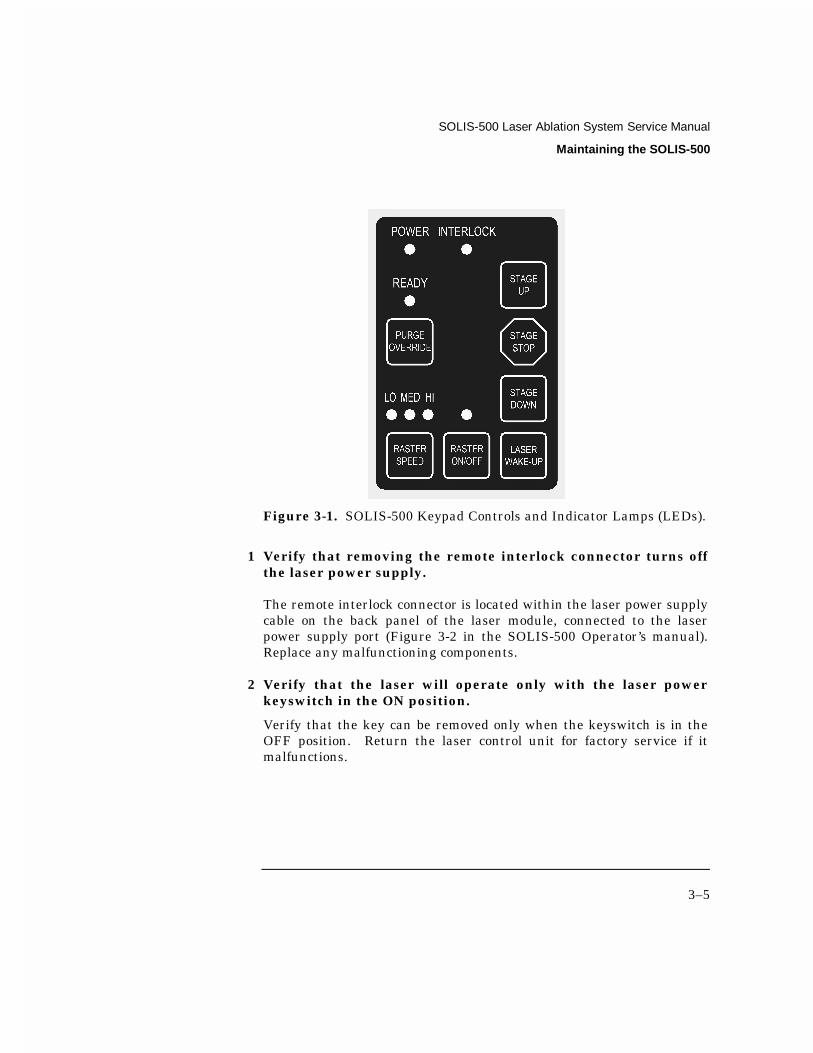
The LED lamps on the front panel of the SOLIS-500 cabinet monitor the safety interlocks and laser operation (See Figure 3-1). The status of the LED lamps indicates several conditions of the laser system:
• Power LED lamp (green) off: no power to the system OR safety interlocks open, laser cannot be fired.
• Power LED lamp (green) on: power is on and safety interlocks closed.
• Ready LED lamp (flashing green): initializing the SOLIS-500 system or purging the gas lines.
• Ready LED lamp (green): system is ready and laser can be fired.
• Interlock LED lamp (orange): safety interlocks open, laser cannot be fired.
WARNING
SOLIS-500 Laser Ablation System Service Manual
Maintaining the SOLIS-500
3–5
Figure 3-1. SOLIS-500 Keypad Controls and Indicator Lamps (LEDs).
1 Verify that removing the remote interlock connector turns off the laser power supply.
The remote interlock connector is located within the laser power supply cable on the back panel of the laser module, connected to the laser power supply port (Figure 3-2 in the SOLIS-500 Operator’s manual). Replace any malfunctioning components.
2 Verify that the laser will operate only with the laser power keyswitch in the ON position.
Verify that the key can be removed only when the keyswitch is in the OFF position. Return the laser control unit for factory service if it malfunctions.

SOLIS-500 Laser Ablation System Service Manual
Maintaining the SOLIS-500
3–6
3 Verify that a time delay exists between turning the keyswitch ON, and the start of laser firing.
It must give enough warning (approximately 10 seconds) to allow action to be taken to avoid exposure to laser radiation. Return the laser control unit for factory service if it malfunctions.
Cooling System Maintenance
Changing the laser cooling system coolant is the primary maintenance task that will be performed. Other items should also be checked periodically to maintain the cooling system properly. Also, the cooling system has to be drained before transportation.
The cooling unit reservoir must only be filled with distilled water, not deionized water. (You may use the water filtered through the Millipore system, before it goes through the ionization cartridge.) Distilled water coolant should have a conductivity of 1-3 Mohms/cm2.
Periodic Checks
1 Circulate coolant through the system for at least 30 minutes every month when the laser is not in use.
Turning the laser power supply key switch ON will turn on the coolant pump motor, and circulate the coolant.
2 Inspect the coolant level in the reservoir every week.
Look through the inspection slot on the back of the cooling unit to see the fluid level. Keep the coolant level in the reservoir approximately halfway between the MIN and MAX markers at all times.
CAUTION

SOLIS-500 Laser Ablation System Service Manual
Maintaining the SOLIS-500
3–7
Draining the Cooling System for Transport
Your cooling system must be completely drained and purged before transport, especially flight transport, since the water might freeze and damage the laser head and cooling unit.
Make sure you have a catch basin ready and in place to collect the coolant.
To drain and purge the cooling system for transport, complete the following steps:
1 Disconnect both coolant lines from the SOLIS-500 laser module (containing the laser head).
The coolant lines have a quick disconnect which automatically seals to prevent coolant loss. Water will start to immediately drain out of the head.
2 Drain the laser head of all coolant.
Drain the laser head completely by draining the water into a catch basin.
3 Remove residual coolant from the laser head.
Blow dry nitrogen at 20 PSI (135 kPa) through either connector to remove any residual coolant, and inspect the coolant for contamination before discarding.
4 Drain the cooling reservoir of all coolant.
To drain the cooler, attach the purge connectors found in the coolant change kit in place of the cooling line fittings. Turn the laser power supply key switch ON, and run the coolant pump to empty the coolant reservoir. Allow the pump to run only as long as coolant continues to flow into a catch basin.
CAUTION

SOLIS-500 Laser Ablation System Service Manual
Maintaining the SOLIS-500
3–8
Do not run the pump dry! This will cause permanent damage.
5 Remove residual coolant from the cooling unit.
Blow dry nitrogen at 20 PSI (135 kPa) into the COOLANT IN (red connector) to remove residual water from the heat exchanger. A small amount of water in the bottom of the reservoir container is not a concern, however, since coolant expansion is now possible.
Filling the Cooling System
The cooling unit reservoir must only be filled with distilled water. (You may use the water filtered through the Millipore system, before it goes through the ionization cartridge.) Distilled water coolant should have a conductivity of 1-3 Mohms/cm2.
The laser cooling unit is incorporated in the laser power supply. The cooling unit reservoir must be filled only with distilled water. Finally all air must be purged from the cooling loop prior to operating the laser.
1 Unplug the laser power supply and wait 1 minute.
2 Remove the plastic cover from the top of the water bottle.
3 Remove the cap from the water bottle.
Open the reservoir cap located on the top of the cooler/power supply module.
4 Fill the reservoir 1/2- 3/4 full with coolant.
An initial fill of approximately 32 ounces (1 liter) will bring the liquid level in the reservoir sight-glass to between 3/4 and completely full. DO NOT OVERFILL or allow any liquid to splash into the cooler chassis. Clean-up all spills immediately.
CAUTION
CAUTION
SOLIS-500 Laser Ablation System Service Manual
Maintaining the SOLIS-500
3–9
Never expose the SOLIS-500 Solids Introduction System to freezing temperatures (below 32°F/0°C). Frozen coolant will destroy the laser head, cause severe cooling unit damage, and void the warranty.
5 Plug the SOLIS-500 laser power supply into the AC power source.
6 Turn the laser power supply power key switch ON.
The cooling unit pump will turn on automatically after power-up, and the coolant reservoir level will drop while air is purged from the lines and laser cavity.
Add more coolant as needed, up to an additional 32 ounces (1 liter), until the reservoir level stabilizes between 1/2 and 3/4 full while the circulating pump is running. Do not allow the pump to run dry.
7 Once stable, turn the pump off and allow trapped air to escape.
Turn the laser power supply key switch OFF to stop the coolant circulating pump, wait 30-60 seconds and turn the key switch ON again. Watch for air bubbles in the coolant lines, or a decrease in the coolant reservoir level. Add more coolant as required to maintain the reservoir level at 1/2-3/4 full.
Repeat this procedure three to five times, or until all air has been purged from the laser cooling system, indicated by the absence of air bubbles in the coolant lines and a stable coolant reservoir level.
Note:
This procedure must be repeated before using the laser whenever the coolant lines have been disconnected.
8 Replace the coolant reservoir cap and plastic cover.
CAUTION

SOLIS-500 Laser Ablation System Service Manual
Maintaining the SOLIS-500
3–10
Tubing Replacement
External Tubing Replacement
The following connections are used:
• CARRIER IN (SOLIS-500) to ICP nebulizer gas: 3/16” i.d.Tygon and 1/8” Tygon tubing.
• SAMPLE OUT (SOLIS-500) to ICP torch adapter: 3/16” i.d. Tygon tubing.
Internal Tubing Replacement
In the event that the sample gas/valve assembly tubing becomes contaminated, it must be replaced. A spare parts kit can be obtained from CETAC. In lieu of purchasing the kit, the tubing can be replaced with TygonTM tubing which is ¼” o.d. and 1/8” i.d.
Figure 3-2. Internal Tygon Tubing.

SOLIS-500 Laser Ablation System Service Manual
Maintaining the SOLIS-500
3–11
The following tubing configuration is used (see Figure 3-3):
Figure 3-3. Internal Tubing Diagram for SOLIS-500.
Ablation cell to valve #1
Valve #1 to tee
Valve #2 to tee Replace With The Same Lengths
Cell base to Valve #2 That Are In The Laser Unit
Valve #1 to carrier gas in
Tee to sample gas out
Valve #2 to vent

SOLIS-500 Laser Ablation System Service Manual
Maintaining the SOLIS-500
3–12
Symptoms that the tubing needs to be replaced can include the following:
• Argon blank contamination.
• Poor stability and poor long-term precision.
• Visible coating of ablated material in transfer line.
When changing the tubing, care must be taken when disconnecting it from the nuts. There are two ferrules that provide sealing pressure. Loss of the ferrules may cause leakage in the tubing assembly. After changing the tubing, test the laser with a known standard to certify that there is no air leakage.
Cleaning the SOLIS-500 Sample Cell Assembly
Removing the Sample Cell Assembly
1 Remove the cover to the SOLIS-500 laser module (there are 9 screws on the back of the unit). Be careful not to disturb the wiring.
Leave the connector to the cover attached (Figure 3-5). If the laser power supply is sitting next to the SOLIS-500 laser module, you should set the cover on top of it, lying on its side.

SOLIS-500 Laser Ablation System Service Manual
Maintaining the SOLIS-500
3–13
Figure 3-4. Removing the Cover of the SOLIS-500 Laser Module.
Figure 3-5. The connector that is attached to the I/O board on one end of the ribbon cable and to the front panel on the other end.

SOLIS-500 Laser Ablation System Service Manual
Maintaining the SOLIS-500
3–14
2 Holding down the interlock switch (Figure 3-6) with a finger, press STAGE DOWN on the SOLIS-500 keypad, lowering the sample platform.
Figure 3-6. Cover Interlock Switch on the SOLIS-500.
3 Remove the sample cell o-ring, located just above the sample platform.
4 Insert the sample cell removal tool, as shown in Figure 3-7.
The tool should be aligned with the 4 holes around the sample cell, so that it is flush with the edge of the sample platform.
Figure 3-7. Insertion of Cell Removal Tool.
SOLIS-500 Laser Ablation System Service Manual
Maintaining the SOLIS-500
3–15
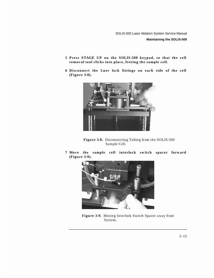
5 Press STAGE UP on the SOLIS-500 keypad, so that the cell removal tool clicks into place, freeing the sample cell.
6 Disconnect the Luer lock fittings on each side of the cell (Figure 3-8).
Figure 3-8. Disconnecting Tubing from the SOLIS-500 Sample Cell.
7 Move the sample cell interlock switch spacer forward (Figure 3-9).
Figure 3-9. Moving Interlock Switch Spacer away from System.

SOLIS-500 Laser Ablation System Service Manual
Maintaining the SOLIS-500
3–16
8 Remove the sample cell assembly (Figure 3-10).
The cell window is not attached to the top of the cell; care should be exercised to prevent window damage.
Figure 3-10. Removing SOLIS-500 Sample Cell for Cleaning.
9 To remove cell window, carefully turn cell assembly upside down into the palm of your hand.
Inspect the cell window for residue (dust) and burn marks. If burn marks are evident, this may be a result of not cleaning the window regularly.
Cleaning Cell Window
1 Use Spectrograde isopropanol or methanol to rinse residue from the window. Allow to dry.
2 When replacing the window, if burn marks are evident, rotate the window so that the burned spot is out of the lasing area. It may be necessary to replace the window.
SOLIS-500 Laser Ablation System Service Manual
Maintaining the SOLIS-500
3–17
Cleaning Sample Cell, O-ring, Various Fittings
1 Use either lab grade isopropanol, methanol, or DI water with a laboratory wipe to clean residue from inside the sample cell and on the o-ring.
2 If necessary, clean the valve fittings and other tubing connections where residue may accumulate.
3 Allow parts to dry before re-assembling.
Replacing Sample Cell Assembly
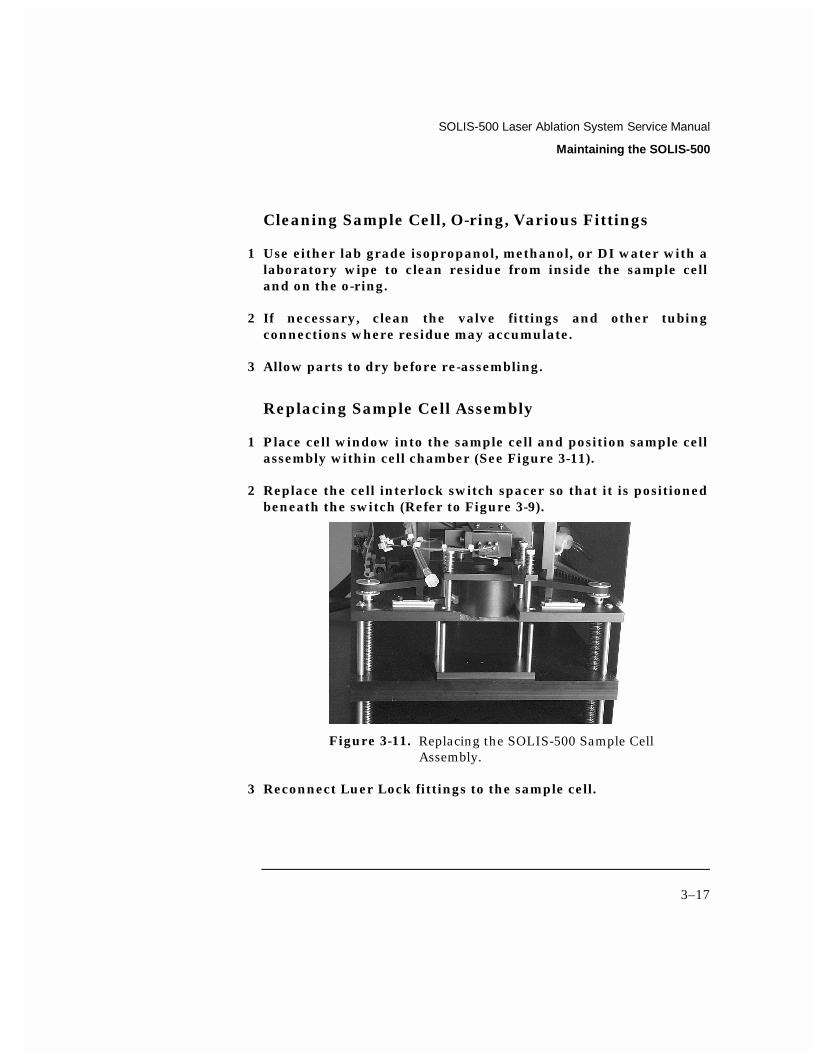
1 Place cell window into the sample cell and position sample cell assembly within cell chamber (See Figure 3-11).
2 Replace the cell interlock switch spacer so that it is positioned beneath the switch (Refer to Figure 3-9).
Figure 3-11. Replacing the SOLIS-500 Sample Cell Assembly.
3 Reconnect Luer Lock fittings to the sample cell.

SOLIS-500 Laser Ablation System Service Manual
Maintaining the SOLIS-500
3–18
4 Holding the cover interlock switch down, press STAGE DOWN on the SOLIS-500 keypad to disengage the cell removal tool. The sample cell should now be seated. Remove the tool from the sample platform.
5 Replace the sample cell o-ring and any tubing or connectors that were removed.
6 Carefully replace the cover to the SOLIS-500 laser module; hold down the door interlock (Figure 3-6) to slide the cover over it. Replace cover screws.
4
Troubleshooting the SOLIS-500

SOLIS-500 Laser Ablating System Service Manual
Troubleshooting the SOLIS-500
4-2
Troubleshooting the SOLIS-500 The SOLIS-500 is both easy to operate and reliable. However, problems with the system may occur. If good performance is not obtained, try to isolate the problem to determine if it originates in the ICP instrument or in the SOLIS-500. If you determine the problem is in the SOLIS-500, check the AC power, the communications interface, the safety interlocks, and the laser head to find the cause of the problem.
This chapter explains how to troubleshoot minor SOLIS-500 problems. If you cannot solve a problem using the steps given in this chapter, contact CETAC Technologies Customer Service and Support or an authorized service representative.
Phone: (800) 369-2822 (USA only)
(402) 733-2829
Fax: (402) 733-1932
Power System Problems
A possible cause of SOLIS-500 malfunction is a problem in the laser power supply. If the Solids Introduction System is inoperative, there may be no power getting to the SOLIS-500. If this is the case, the READY indicator (green LED) on the front of the laser module is unlit. To troubleshoot this problem, complete the following steps:
DANGER - HIGH VOLTAGE. The power supply housed in the laser electronics module contains lethal current and voltage levels. Do not attempt any service beyond described troubleshooting procedures.
WARNING

SOLIS-500 Laser Ablation System Service Manual
Troubleshooting the SOLIS-500
4–3
1 Check that the AC line cord is connected to the AC outlet, and the AC power switch is turned on.
Connect the cord if it is not already plugged in to the AC outlet, and turn the power switch on. If the cord is connected and the rear power switch is turned on, and the SOLIS-500 front panel display is not operational, continue troubleshooting with step 2.
2 Check the wall outlet.
Move the AC line cord to a known good outlet. Have a qualified electrician check the AC power outlet.

SOLIS-500 Laser Ablation System Service Manual
Troubleshooting the SOLIS-500
4–4
Figure 4-1. Wiring and Pinout Diagram.

SOLIS-500 Laser Ablation System Service Manual
Troubleshooting the SOLIS-500
4–5
Tampering with the SOLIS-500 laser power supply while troubleshooting power problems may result in personal injury or death, and void the warranty.
NOTE:
The SOLIS-500 has no user replaceable fuses.
If the AC power input is within specifications and the SOLIS-500 will not operate, call CETAC Customer Service and Support, or an authorized service representative.
Interface Problems
A malfunction of the Solids Introduction System can indicate a problem with the communication cable. The following section explains how to troubleshoot this problem.
Communication Cable Problems
The first step in troubleshooting suspected interface problems is to check the communication cable from the SOLIS-500 laser module to the laser power supply module. To do so, complete the following steps:
1 Check the READY indicator (green LED) on the front of the SOLIS-500 to ensure the power is on.
2 Check the communication cable to ensure it is plugged in to the LASER HEAD I/O port of the laser power supply module.
WARNING
WARNING
SOLIS-500 Laser Ablation System Service Manual
Troubleshooting the SOLIS-500
4–6
3 If the cable is plugged in, ensure that the connector is properly oriented, fully seated, and the thumbscrews are fully and evenly tightened.
Safety Interlock Problems
There are several safety interlocks in the Solids Introduction System to protect personnel from accidental laser beam and high voltage exposure, and to protect the laser from overheating.
The SOLIS-500 laser module contains two interlocks to protect personnel from accidental laser beam exposure. If the cover is removed or the sample platform is lowered during laser firing, the system will shut down and prevent further operation until the faults are corrected.
Do not deactivate or tamper with safety interlocks. Deactivation of safety interlocks is done solely at the user’s risk. Call CETAC Technologies Customer Service and Support if safety interlock-related problems occur.
The laser power supply/cooling unit contains four interlocks to protect personnel from high voltage exposure, and to protect the laser from overheating. If the laser controller cover is opened, the remote interlock has a problem, the cooling system overheats, or the coolant flow is interrupted, the system will shut down and prevent further laser operation until the faults are corrected.
Laser Module Interlocks
Sample Platform. The sample platform interlock is located inside the laser module. A switch opens whenever the sample stage is lowered, ensuring that the laser cannot be operated when the sample chamber is unsealed.
WARNING

SOLIS-500 Laser Ablation System Service Manual
Troubleshooting the SOLIS-500
4–7
SOLIS-500 Cover. If the laser module cover is opened and/or removed, power will automatically shut down to the SOLIS-500 laser module to protect personnel from high voltage exposure.
Laser Power Supply Module Interlocks
Coolant Flow. The coolant flow interlock ensures that coolant is flowing through the laser head. The coolant flow is monitored by a magnetic switch that is located in the coolant loop.
If a coolant flow fault occurs, the coolant flow has been stopped by an obstruction in the cooling loop or coolant hoses, or the circulating pump has stopped due to a pump motor failure or blown fuses.
To test, check for turbulence in the coolant reservoir. If the coolant in the reservoir is not moving, there is a blockage in the cooling loop that must be cleared; drain the cooling system as described in “Cooling System Maintenance”, Chapter 7 of this manual.
If there are air bubbles in the coolant lines, there could be a coolant flow fault. A laser fault will appear on the power supply. To correct the problem, turn the power supply key on for a few minutes and then turn it off. Repeat this several times until no air bubbles exist. The fault indicators should disappear.
Laser Power Supply Cover. If the Laser Power Supply Cover is opened for any reason, the laser cannot be operated.
Remote Interlock. If the remote interlock connection is broken by a bad cable or a fault in the interlock loop, the laser cannot be operated.
Coolant Temperature. The coolant temperature interlock ensures that the coolant temperature does not exceed an acceptable level. The coolant temperature sensor is located on the heat exchanger inside the cooling unit and will cause a fault if water temperature exceeds 150oF (65oC).

SOLIS-500 Laser Ablation System Service Manual
Troubleshooting the SOLIS-500
4–8
Laser Problems
A malfunction of the SOLIS-500 laser can indicate a problem with the laser electronics, laser pumping energy, the cooling system, or with the laser flashlamp. The following sections explain how to troubleshoot these problems.
DANGER - INVISIBLE LASER RADIATION. The SOLIS-500 uses a Class IV Nd:YAG Laser. The output beam is, by definition, a safety and fire hazard. Precautions must be taken during use and maintenance to prevent accidental exposure to direct or reflected radiation from the laser beam.
No Laser Output
No AC power, low laser pumping energy, or improperly connected control cables can result in no laser output. To troubleshoot this problem, complete the following steps:
1 With the AC power off and the power cord unplugged, check all the electrical connections between the SOLIS-500 and laser power supply/cooling unit.
Make sure all connections are secure, that the cables are installed correctly, and not causing the system to malfunction.
If the cables are connected correctly, continue troubleshooting with step 2.
DANGER - HIGH VOLTAGE. The SOLIS-500 laser unit contains electrical circuits operating at lethal voltage and current levels. Always unplug and wait at least one (1) minute to allow capacitors to bleed down before servicing any part of the laser system.
WARNING
WARNING

SOLIS-500 Laser Ablation System Service Manual
Troubleshooting the SOLIS-500
4–9
2 Check the Q-switch.
The Q switch, when on, controls the pulse repetition rate. The Q switch should be on. If not, correct by toggling the Q-switch button to ON. If the Q switch is already on, continue troubleshooting with step 3.
3 Check the laser output energy setting.
If set below the lasing threshold, correct it. Refer to the laser output efficiency data supplied with the laser head for allowable minimum and maximum values.
Modification of the furnished laser power supply is done solely at the user’s risk. Call CETAC Technologies Customer Service and Support if power system-related problems occur.
Low Laser Efficiency
Laser output energy below nominal may suggest gradual lamp and/or cooling system degradation. These characteristics are normal over time, and with large laser shot accumulations (>40 million). Contaminated coolant, a laser flashlamp that needs to be replaced, or a resonator in need of adjustment can all result in low laser efficiency.
To troubleshoot this problem, complete the following steps:
1 Inspect the coolant for contamination.
The coolant should be clear, and free from contaminants; there should not be any visible particulates or organic contaminants in the coolant. Black particulates are a sign of pump wear, and green or black slime is an indication of organic substances (algae) growing in the cooling system. See Chapter 3, “Maintaining the SOLIS-500” for checking and replacing the coolant.
If the coolant, and cooling system, is not contaminated, continue troubleshooting with step 2.
WARNING
SOLIS-500 Laser Ablation System Service Manual
Troubleshooting the SOLIS-500
4–10
Note:
If contaminated coolant is suspected, the cooling system must be completely purged and properly cleaned prior to operating the laser. Contact CETAC Technologies for instructions on how to clean your laser cooling system if you find organically contaminated coolant.
2 Check the laser flashlamp age.
Replace the laser flashlamp if over 40 million shots. Shot number is located on the back of the laser power supply. Contact CETAC Technologies for service on replacing the flashlamp or read the instructions in the SOLIS-500 Service Manual.
Flashlamp Replacement
Handle the flashlamp only with talc-free finger cots or gloves. This is a delicate operation. If there are any questions, please contact CETAC Technologies for service on replacing the flash lamp.
Make sure the PFN (Pulse Forming Network) is discharged and the laser key switch is OFF before removing or replacing the flashlamp.
1 Disconnect the electrical cables and the coolant lines from the laser head. Attach the purge connectors and drain the laser head. Blow 20 pi dry Nitrogen through either connector to remove the residual water from the head.
2 With the laser head set flat on it mounting feet or mounted in the LSX-200, remove the lamp access cover from the laser head by pushing and rotating counterclockwise. Removal of the cover will reveal the plastic lamp insertion tool.
CAUTION
CAUTION

SOLIS-500 Laser Ablation System Service Manual
Troubleshooting the SOLIS-500
4–11
3 Remove the flashlamp by grabbing the lamp insertion tool and gently pull the lamp out of the laser. The lamp insertion tool is connected to the laser flashlamp in the head.
It is very important to pull straight and evenly to avoid breaking the lamp!
4 Remove the retaining clip and the lamp insertion tool from the lamp. Gently pry, using the housing for leverage, to pull the lamp a short distance (approximately 1/4” or 6.4 mm ) from the pump cavity and free it from its submerged cathode socket at the opposite end of the pump cavity. Once gently pried, it should slide easily out the cavity. Take care when sliding the lamp out of the Laser Head, not to get water on the fold prism located just to the left of the lamp.
5 Clean the new lamp with methanol or acetone. Install the lamp insertion tool and retainer clip onto the lamp.
6 Very slightly dampen the new lamp with distilled water so that it slides easily through the O-rings inside in the Laser Head. This can be done by touching your finger cot in a single drop of the water and then wipe on the lamp envelope. Manually slide the lamp into the laser. It should slide easily.
7 Replace the lamp access cover by pushing and rotating clockwise, making sure that the sealing o-ring is properly installed between the lamp access cover and the Laser Head. You will feel a positive contact with the cathode connector when the lamp is properly installed. The lamp will “bottom out” solidly when totally installed. If unsure about whether the lamp is fully seated, pull the lamp back out approximately 1/2” (1.3 cm) and reseat.
CAUTION

SOLIS-500 Laser Ablation System Service Manual
Troubleshooting the SOLIS-500
4–12
Operation of the pump with a flashlamp that is not fully seated will flood the Laser Head and void the warranty, causing permanent laser damage. If there is any doubt about the Flashlamp replacement procedure, please contact CETAC Technologies (1-800-369-2822).
8 Reconnect the coolant lines to the Laser Head and cycle the pump (Power ON and OFF) briefly. Check the lead where it exits from the pump cavity for any leaks. If necessary, use a flashlight to observe the end of the lamp envelope.
9 Purge the Laser Head with dry Nitrogen as described below.
Nitrogen Purge The laser head is factory pressurized with UHP (Ultra High Purity) dry Nitrogen to prevent condensation on the laser optics. If any cover or access screw is removed for any reason, the laser head should be purged again with UHP Nitrogen.
This is the Nitrogen Purge procedure:
1 Remove the two rear purge port sealing screws on the side of the laser head. You will remove two screws at a time.
2 Connect 5 PSI dry Nitrogen to one of the seal screw holes, using the Schrader valve/4-40 screw adapter supplied in the completion kit.
3 Purge the head for 20 minutes. If the lamp has been changed, it is necessary to purge the laser head for 45 minutes to be sure all excess water has been removed.
4 Install the purge sealing screw and disconnect the Nitrogen source from the Schrader valve.
5 Remove the front two purge port sealing screws. Purge two screw holes at a time. Repeat steps 2-4 for the front two purge
CAUTION

SOLIS-500 Laser Ablation System Service Manual
Troubleshooting the SOLIS-500
4–13
sealing screws and you have completed the Nitrogen purge procedure.
Contact CETAC Technologies for any repair actions necessary beyond those described in this manual. Attempts to adjust, repair, or replace optics may cause additional problems and void the warranty.
Stability Problems
Signal stability can be affected by many different factors: gas flow, sample type, sample surface, raster speed, ICP problems, etc. Refer to Chapter 5, “Using the SOLIS-500 Solids Introduction System in the Operator’s manual” for optimization guidelines.
Plasma Problems
Plasma flickers excessively or is unstable
• The most likely cause of plasma instability is a leak in the gas line connections. Make sure all connections to the SOLIS-500 are tight and correct. Very high gas flow may also cause plasma instability. Refer to “System Optimization” in Chapter 2, “Verifying Installation.”
Replacing and Aligning the Laser Head Replacing the Laser Head
• To replace the laser head in the SOLIS-500, first remove the 9 screws that are on the back of the unit.
• Remove the front panel and set it aside. The ribbon cable might have to be removed.
CAUTION
SOLIS-500 Laser Ablation System Service Manual
Troubleshooting the SOLIS-500
4–14
• Remove the two screws on the mount that hold the black communication cables and coolant hoses to the unit.
• Remove the three screws that hold the laser head to the vertical mount.
• Once the laser head is removed proceed to drain the coolant. See Chapter 3, “Draining the cooling system for transport.”

SOLIS-500 Laser Ablation System Service Manual
Troubleshooting the SOLIS-500
4–15
Figure 4-2. Optical Schematic for the SOLIS-500.
SOLIS-500 Laser Ablation System Service Manual
Troubleshooting the SOLIS-500
4–16
Laser Head Alignment This is the alignment process for the SOLIS-500 laser head.
This process must be performed in a secured area. All persons in this are must wear the appropriate protective eyewear!
This is the Nitrogen Purge procedure:
1 Connect the cooling lines and the laser power cables to the laser power supply.
2 Connect the benchtop power supply to the input jack on the back panel of the SOLIS-500.
3 Fill the laser power supply reservoir with distilled water. Check the coolant level to be between the min and max level indicators on the back of the power supply.
4 Remove the top cover of the SOLIS-500.
5 Depress the safety interlock switch (it must remain depressed for the remainder of this alignment process).
6 Turn the power to ‘ON’ for the SOLIS-500 and Laser power supply.
Note:
The laser power supply should be allowed to warm-up for 10 minutes prior to firing. Priming the pump may be necessary.
7 Remove the laser diode mount and adjust the focus (by rotating the focusing ring) to achieve the smallest spot on the sample platform with the platform all the way down.
CAUTION

SOLIS-500 Laser Ablation System Service Manual
Troubleshooting the SOLIS-500
4–17
8 Insert the alignment tool into the alignment platform.
9 Close the sample cell.
10 Toggle the Q-switch of the laser power supply to ON.
11 Ensure that the raster position is all the way to the left (parked position).
12 To begin laser firing, press the laser ‘RUN’ switch on the laser power supply (to stop press it again).
13 Open the sample cell.
14 Examine the ablated mark. It should extend to the very right edge of the dowel pin.
15 Adjust the limit switch set screw to correct any error in the beginning laser position.
16 Repeat steps 1.6 through 1.12 until the desired starting position is attained.
17 Close the sample cell.
18 Depress ‘RUN’ on the laser power supply to turn laser ‘ON’. .
19 Turn raster to ‘ON’ until it deactivates the left limit switch.
20 Turn raster to ‘OFF’ (this will allow it to raster at a much higher rate). It will raster right until it hits the right hand limit switch, then left until it hits the left hand limit switch, where it will stop.
21 Depress ‘RUN’ on the laser power supply to turn the laser ‘OFF’.
SOLIS-500 Laser Ablation System Service Manual
Troubleshooting the SOLIS-500
4–18
22 Open the sample cell and examine the laser head alignment disc noting how far right the laser ablation mark is to the right edge of the alignment disc (approximately 5mm long) when the right limit switch set screw is adjusted correctly.
23 If necessary, adjust the right limit switch set screw and repeat steps 1.14 through 1.19.
24 In the parked position, adjust the laser diode mount to point the laser diode to the beginning of the ablation path.
25 Repeat steps 1.16 and 1.17 to ensure the diode follows the ablation path.
26 Once the alignment is complete, secure the left and right limit switch set screws in position using Loctite 222.

SOLIS-500 Laser Ablation System Service Manual
Troubleshooting the SOLIS-500
4–19
Figure 4-3. Front View of SOLIS-500 without Front Cover.
Control PCB (Overview) The SOLIS-500 control PCB consists of the following:
• Gas control
• Raster section.
• Safety interlocks.
• Motorized sample stage.
• Diode aiming for sample placement.
• Keypad control.

SOLIS-500 Laser Ablation System Service Manual
Troubleshooting the SOLIS-500
4–20
Gas Control The Gas control system consists of two 3-way valves, the purge valve and the inject valve.
Three different valve states can occur: Purge, inject, or bypass.
When the sample stage is open, both valves are in the off position, the sample cell is bypassed and the carrier gas is passed directly to the ICP torch.
When the sample stage is closed, the purge valve goes to the on position, the carrier gas then passes through the sample cell and out to vent. This condition is timed to last 60 seconds when the valve times out
After 60 seconds, the inject valve switches to the On position. The carrier gas then passes through the sample cell and on to the ICP torch. The purge condition can also be bypassed via a push button (‘Purge Override’) on the SOLIS keypad.
Raster Section The raster section of the SOLIS consists of a .9 Degree stepper motor coupled to an x stage movement.
The x stage movement has 5mm travel offset from the center of the sample and moving outwards towards the edge of the sample. When the raster stage reaches the outer edge of its travel, it will switch directions and return to the center. This will repeat until the raster stage is turned off.
Rastering can be operated in 4 different modes:
• Low
When operated in raster on low mode the raster stage will travel at 10um per second, the stepper is ½ stepped.
• Medium
When operated in raster medium mode the raster stage will travel at 20um per second, the stepper is ½ stepped.

SOLIS-500 Laser Ablation System Service Manual
Troubleshooting the SOLIS-500
4–21
• High
When operated in raster high mode the raster section will travel at 50um per second, the stepper is ½ stepped.
• Off / Park
When operated in Raster off park mode the raster section will travel at 300um per second, the stepper is full stepped, the stage will return to the offset midpoint of the sample, and park.
All 4 modes of operation can be selected on the keypad of the SOLIS: Raster speed switch with Low, Med., High LED indicators, and Raster off park with LED indicator. Also, the Low, Med., and High raster speeds can be easily varied for specific applications.
Safety Interlocks The SOLIS has 2 interlocks:
Sample Cell Interlock
The Sample cell interlock is designed to protect the user from exposure to IR or UV radiation, depending on the option package. This is achieved through a switch located above the sample cell. It insures that the laser will not fire unless the sample stage is in the closed position, and no radiation can escape.
Cabinet Interlock
The cabinet interlock is designed to protect the user from accidental shock.
This is achieved through a switch at the top of the cabinet, which insures that power is disconnected from the unit if the top cover is removed.

SOLIS-500 Laser Ablation System Service Manual
Troubleshooting the SOLIS-500
4–22
Motorized Sample Stage The motorized sample stage consists of a DC gear head motor, a belt and pulley system, and two switches.
When the stage is lowered the stage depresses a switch and turns off the motor driver chip.
When the stage is raised the stage makes contact with the sample cell and depresses a switch located above the sample cell turning off the motor driver chip.
The sample stage can also be controlled by the SOLIS keypad Sample stage up sample stage stop and sample stage down.
The sample stage also incorporates a safety feature to avoid user injury.
This feature will drive the motor driver circuitry into oscillation if the force on the stage exceeds approximately 3 pounds.
Diode Aiming System The Laser diode aiming system switches a 3mm prism in and out of the beam path, which focuses a 670nm laser beam onto the sample surface.
The prism is switched in and out of the laser path via a 12 VDC spring loaded solenoid and a RC network.
When the sample platform is in the open position, after a 3 second delay the prism is moved into the laser path and the diode laser is switched on. After approximately 3 minutes the diode is switched off to preserve the lifetime of the diode. The turn on delay is to insure time for the solenoid firing capacitor time to charge in the event of a door open power up. There is also a switch on the keypad to restart the aiming timing sequence (Pointer wake up).
Keypad Control The keypad control of the SOLIS system will control all necessary functions of the system and display status of the interlock, valve status, Raster on off, and raster speed settings.


