SOLiT: an automated system for synthesising reliable sequential circuits with multilevel logic implementation C.-S. Lai C.-L. Wey Indexing terms: Coding fechniques, Concurrent error detection, Logic, Partitioning algorithm Abstract: The paper presents SOLiT, an automa- ted system for synthesising reliable sequential cir- cuits with multilevel logic implementation. The reliability enhancement is achieved by using con- current error detection scheme with coding tech- niques. The system receives the behavioural description of finite-state machines, determines the required checker circuits, and generates the physi- cal layouts. The synthesised circuits can detect multiple unidirectional errors. A novel output partitioning algorithm is presented to reduce the hardware cost of the required checker circuits. Results show that the overhead for reliability enhancement of the synthesised sequential circuits is relatively low. Introduction With the ever-increasing complexity of digital applica- tions, the issue of reliability has become very important in VLSI designs. It would be preferable for the circuits to be designed such that they will indicate any malfunction during normal operation and not produce an erroneous result without error indication [l]. Thus, a mechanism for concurrent error detection must be installed to detect transient faults before they cause undesirable results [2]. Concurrent error detection can be achieved by using self- checking circuits [l, 31 to detect the presence of both transient and permanent faults. A self-checking checker, comprised of a functional circuit and a self-checking checker, is designed to produce an error signal for some normal circuit inputs whenever a fault from a specified set of faults occurs within the circuit. Numerous self-checking sequential circuit design alter- natives have been reported [4-81, in which circuits are encoded with either m-out-of-n (m/n) codes or Berger codes for unidirectional errors and detected by the corre- sponding code checkers. Results in Reference 8 show that the code length of m/n and Berger code checkers grows linearly with the number of outputs in a functional circuit, whereas the complexity of the checker grows rapidly. For a reasonably large sequential circuit, the hardware cost of the required checker circuit may be much higher than that of the functional circuit. This has $3 IEE, 1995 Paper 1378E (C2, ElO), first received 20th September 1993 and in revised form 23rd May 1994 The authors are with the Department of Electrical Engineering, Michi- gan State University, East Lansing, MI 48824-1226, USA IEE Proc.-Comput. Digit. Tech., Vol. 142, No. I, Junuary 1995 limited the implementation of the self-checking circuit design concept for large sequential circuits. However, the hardware cost for the required checker circuit may be reduced significantly if a number of smaller checker cir- cuits can be used instead [SI. In other words, if the output functions can be partitioned into groups and each group is tested by a smaller checker circuit, the total hardware cost for all these smaller checker circuits may be much less than that of a large checker circuit. 2 Output partitioning algorithm Prior to the discussion of the output partitioning algo- rithm, we first consider the development of an efficient matrix partitioning algorithm. 2.1 Problem statement and development Consider a matrix [cijIsxr, where cij is the binary entry at the ith row and the jth column. Let Ri be a collection of column indices j with cij = 1, i.e. Ri = {j I cij = 1). Also, let IRiI denote the cardinality of Ri and R,, = max { I RI 1, I R, 1, . .. , I R, I }. A matrix is called a k-set if R,, = k. Our objective is to develop an algorithm that efficiently partitions the columns of a given k-set matrix into a minimal number of r-set submatrices. For simpli- city, first consider the case r = 1. Let C = { 1, 2, . . . , t} be the set of the column indices of a given matrix and G, be a collection of the column indices in the ith partitioned group. The problem can be formulated as follows. Probleml: Find g=minI{G,JuG,=C, nG,=@, I G, n Ri I < 1 for all p and i} I The condition uG, = C and nG, = 0 implies that G,s are the disjoint subsets of C, while the condition I G, n Ri I < 1 for all p and i means that a G, cannot contain more than one element in a Ri. Thus, the minimal number of partitioned groups g will not be lower than R,,, . Based on these constraints, two simple properties are summarised: Property 1, any two elements of Ri cannot be in the same G, and Property 2, R,, < g. Apparently, R,,, is the lower bound on the number of partitioned groups. R,,, = t (the number of columns) implies that a given matrix is partitioned into m 1-set submatrices and each matrix contains only one column. Since a Ri set is a collection of 1-entry column indices in the ith row of a given matrix, by property 1, a G, con- tains at most one element of a Ri set. The question that arises is: which column should be selected first when a G, set is constructed? In this development, a simple rule is employed to establish the selection priority. Let A and B 49
Transcript
SOLiT: an automated system for synthesising reliable sequential circuits with multilevel logic implementation
Abstract: The paper presents SOLiT, an automa- ted system for synthesising reliable sequential cir- cuits with multilevel logic implementation. The reliability enhancement is achieved by using con- current error detection scheme with coding tech- niques. The system receives the behavioural description of finite-state machines, determines the required checker circuits, and generates the physi- cal layouts. The synthesised circuits can detect multiple unidirectional errors. A novel output partitioning algorithm is presented to reduce the hardware cost of the required checker circuits. Results show that the overhead for reliability enhancement of the synthesised sequential circuits is relatively low.
Introduction
With the ever-increasing complexity of digital applica- tions, the issue of reliability has become very important in VLSI designs. It would be preferable for the circuits to be designed such that they will indicate any malfunction during normal operation and not produce an erroneous result without error indication [l]. Thus, a mechanism for concurrent error detection must be installed to detect transient faults before they cause undesirable results [2]. Concurrent error detection can be achieved by using self- checking circuits [ l , 31 to detect the presence of both transient and permanent faults. A self-checking checker, comprised of a functional circuit and a self-checking checker, is designed to produce an error signal for some normal circuit inputs whenever a fault from a specified set of faults occurs within the circuit.
Numerous self-checking sequential circuit design alter- natives have been reported [4-81, in which circuits are encoded with either m-out-of-n (m/n) codes or Berger codes for unidirectional errors and detected by the corre- sponding code checkers. Results in Reference 8 show that the code length of m/n and Berger code checkers grows linearly with the number of outputs in a functional circuit, whereas the complexity of the checker grows rapidly. For a reasonably large sequential circuit, the hardware cost of the required checker circuit may be much higher than that of the functional circuit. This has
$3 IEE, 1995 Paper 1378E (C2, ElO), first received 20th September 1993 and in revised form 23rd May 1994 The authors are with the Department of Electrical Engineering, Michi- gan State University, East Lansing, MI 48824-1226, USA
IEE Proc.-Comput. Digit. Tech., Vol. 142, N o . I , Junuary 1995
limited the implementation of the self-checking circuit design concept for large sequential circuits. However, the hardware cost for the required checker circuit may be reduced significantly if a number of smaller checker cir- cuits can be used instead [SI. In other words, if the output functions can be partitioned into groups and each group is tested by a smaller checker circuit, the total hardware cost for all these smaller checker circuits may be much less than that of a large checker circuit.
2 Output partitioning algorithm
Prior to the discussion of the output partitioning algo- rithm, we first consider the development of an efficient matrix partitioning algorithm.
2.1 Problem statement and development Consider a matrix [cijIsxr, where cij is the binary entry at the ith row and the jth column. Let Ri be a collection of column indices j with c i j = 1, i.e. Ri = { j I cij = 1). Also, let IRiI denote the cardinality of Ri and R,, = max { I R I 1 , I R , 1 , . . . , I R , I }. A matrix is called a k-set if R,, = k. Our objective is to develop an algorithm that efficiently partitions the columns of a given k-set matrix into a minimal number of r-set submatrices. For simpli- city, first consider the case r = 1. Let C = { 1, 2, . . . , t } be the set of the column indices of a given matrix and G, be a collection of the column indices in the ith partitioned group. The problem can be formulated as follows.
P r o b l e m l : Find g = m i n I { G , J u G , = C , nG,=@, I G , n Ri I < 1 for all p and i} I
The condition uG, = C and nG, = 0 implies that G,s are the disjoint subsets of C, while the condition I G, n Ri I < 1 for all p and i means that a G, cannot contain more than one element in a R i . Thus, the minimal number of partitioned groups g will not be lower than R,,, . Based on these constraints, two simple properties are summarised: Property 1, any two elements of Ri cannot be in the same G, and Property 2, R,, < g.
Apparently, R,,, is the lower bound on the number of partitioned groups. R,,, = t (the number of columns) implies that a given matrix is partitioned into m 1-set submatrices and each matrix contains only one column. Since a Ri set is a collection of 1-entry column indices in the ith row of a given matrix, by property 1, a G, con- tains at most one element of a Ri set. The question that arises is: which column should be selected first when a G, set is constructed? In this development, a simple rule is employed to establish the selection priority. Let A and B
49
be any two rows of a given matrix, B covers A if B has ones everywhere A has ones. Thus the ith row covers the ath row implies that R, E R , .
Theorem I: Let G,s be some sets that satisfy U G, = C and nG, = 0, and I G, n R, I < 1, for all i. If R, G R, , then 1 G, n R, I < 1 for all p .
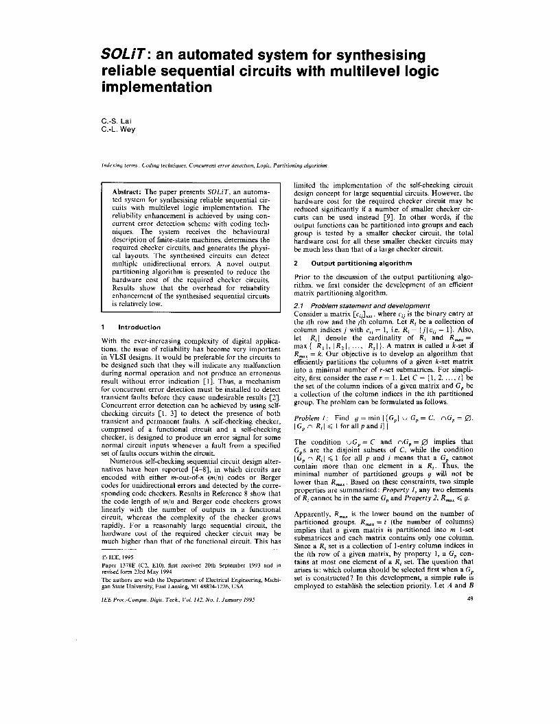
A row is essential if it is not covered by any other rows. For example, consider the matrix in Fig. la which
(4 (b) Fig. 1 FSM, ex4.kiss2 a Original output function matrix b Reduced output function matrix
consists of 21 rows and 9 columns. There exist only four essential rows in the matrix as shown in Fig. lb, referred to as a reduced matrix. Therefore problem 1 can be refor- mulated as follows.
Problem 1‘: Find g = min I (G , I uG, = C, nG, = 0, I G , n Ri I < 1 for all p and essential rows i} I
In this development, a table that records the column count, i.e. the number of ones in each column, of the reduced matrix is used to establish the selection priority. A column with a higher count means that it belongs to more Ri sets and therefore such column will be more dif- ficult to satisfy the condition I G, n R , I < 1. Thus, the column with a higher count should have a lower selection priority. According to the column count of a reduced matrix, let C , = (C,,, C,,,, ..., C,,} denote the corre- sponding descending pnonty set of the column indices, i.e. the priority of C , is higher than that of C,, if a < b. Note that if two columns have the same count the lower column index is defined to have a higher priority. For example, according to the reduced matrix of Fig. lb, columns 2, 3, 4, 5, 6, 8 and 9 have 1-counts, while columns 1 and 7 have 2-counts. Thus, the priority set is C , = (2, 3,4 , 5, 6, 8, 9, 1, 7). The priority set C, is used to construct the minimal sets G,s.
Let S, be an ordered set of the column indices. Each G, is constructed by always selecting the first element in S, , i.e. the one with the highest priority, at each iteration. More specifically, the process starts with constructing G,, where S , = C , is initialised. G, first selects the first element in Sc, i.e. C,, . By property 1, if a set R, contains the element C,, which has been selected by G,, then the remaining elements in R, cannot be selected by G,. Therefore the elements in those Ris containing C,, must
50
be excluded from S , , i.e. S, = S,- U ( R , 1 C,, E R,} and the updated set S , is again used by G, to select the next element. The process is repeated until the updated S, is an empty set, i.e. S , = 0. For example, S, = C , = (2, 3, 4, 5, 6, 8, 9, 1, 7) is initialised and G, selects the first element ‘2’. Since ‘2’ is contained in R,, = { 1, 2, 7,9) , the elements in R,, must be excluded from S , . As a result, S, = (3, 4, 5, 6, 8). Similarly, the elements ‘3’, ‘4, and ‘6‘ are selected subsequently before concluding S, = 0 i.e.
Once G, is constructed, G,, , selects its members from the initial priority set S, , where S , = C,- U:=, G, . The same procedure described above is repeated until uG, = C. For example, G, selects its members from the updated set S , = C, - G1 = (5, 8, 9, 1, 7). Thus, G2 = (5, 8, 9) is generated. Finally, G , = (1) and G , = (7) are con- structed in a similar manner.
G , = (2, 3, 4, 6 ) .
The procedure is summarised in algorithm 1.
Algorithm I: (r = 1)
derive R, sets. Step I : Generate reduced output function matrix and
Step 2: Establish selection priority and generate set
3.1: (Selection) U = U + 1; G, = 0; S, = C,; C , = the first element of S,; G, = G, U { C , ) ; S, = S c - U ( R i I C , E R,};
Repeat
Until S , = 0; 3.2: (Compaction) C , = C,- G,;
Until C , = 0; Similarly, problem 1’ can be generalised as:
Problem 2: To find G = min I {G,( uG, = C, nG, = 0, I G, n R, I 6 r for all p and essential rows i) I
The condition, 1 G, n R, I < r for all p and essential rows, implies that a G, cannot include more than r elements in R , . Similar to the algorithm 1, for r = 2, each element in the selection priority set C , is a pair (U, U), where U, U E R i . A pair (U, U) may occur in some R, s and the number of such Ris is referred to as the pair count of (U, U). The priority is established in accordance with the pair count. A pair with higher count has lower priority. In addition, if the pairs (U,, U,) and (U,, U,) have the same count, the priority is determined by their orders, i.e. (U,, U,) < (ut, U,) if U, < U,, or U, = U, and U, < U,. The selection/ compaction process is the same as step 3 in algorithm 1. For the general case r, each element in the selection pri- ority set C , is a r-tuple of the elements in R i .
According to the construction of the priority set C , , its cardinality becomes larger as r increases. The partition- ing process is getting more complicated as r increases. However, our empirical results have shown that the gen- eration of r-set submatrices can be obtained by combin- ing a number of 1-set submatrices [9]. In addition, the total hardware cost of both l/tl and I/ t , checkers is gen- erally less than that of 2/(t, + t , ) checker. Therefore, the efficient algorithm for r = 1 is sufficient and recommend- ed in this implementation.
2.2 Output partitioning algorithm and its implementation
Algorithm 1 presents an efficient matrix partitioning algorithm which is used as the output partitioning algo-
I E E Proc.-Comput. Digit. Tech., Vol. 142, No. I , January 1995
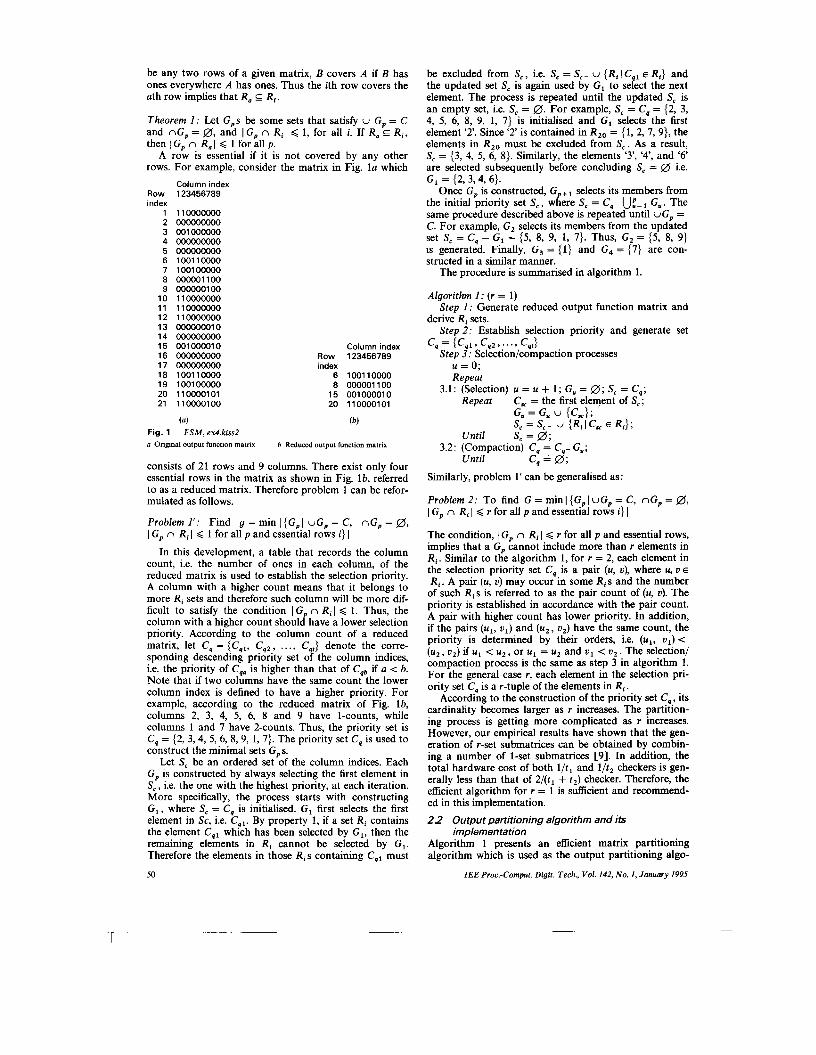
rithm. As shown in Fig. la, the matrix is formed by the output portion of a FSM. To demonstrate the effec- tiveness of the partitioning algorithm, experimental results of some MCNC FSM [lo] benchmark examples are listed in Tables 1 and 2, respectively, where #i, #p, #o, and # s represent the numbers of inputs, product terms, outputs, and states, respectively. The column max. # 1 s shows the value of k as defined previously. The column ‘checker’ indicates the checker, either m/n code checker or B(I, K ) Berger code checker, required for the self-checking circuit design without partitioning the output functions. Since none of existing checker design approaches can be universally and optimally imple- mented for any code length, the experimental results are obtained by implementing the design approaches selected with the following priority: For m/n code checkers: if m 2 3, 4m 2 n > 2m, the checker design in Reference 12 is applied; if n is small, the checker designs with 2-level implementation 1131 or 3-level implementation [14] are employed; and if n =2m or n = 2m & 1, the checker designs in References 13 and 15 are implemented ; and the checker design in Reference 16 is used for the remaining cases. For Berger code checkers, the best design among the approaches in References 16-19 is used. Note that m/n code checker is generally realised with less gate level and gate count than Berger code checkers at the cost of
higher gate count. However, Berger code checkers require less check bits. The m/n code checker is generally used when the gate level is of concern.
In our implementation, we first generate the parti- tioned groups for r = 1 using algorithm 1. Then we combine those partitioned groups with I G,J 4 2 as another partitioned group, where the group is checked by either a m/n code or a Berger code checker. As discussed in example 1, the output functions of ex4.kiss2 can be partitioned into four groups, where I G I I = 4, I G, I = 3, I G 3 I = 1, and 1 G, I = 1. Since both I G, I and I G, I are less than 2, both groups are combined. Thus, the circuit requires the lj5, 1/4, and 2/4 checkers as listed in Table 1. As discussed in Section 1, without partitioning its output functions, the circuit requires a 4/13 checker which needs 105 gates with 7 gate levels, but the checker hardware can be reduced to 23 gates and 3 levels. The reduction in both hardware cost and performance degradation is sig- nificant.
3 Development of SOLiT
SOLiT, an automated system for synthesising self- checking sequential circuits with multilevel logic imple- mentation [22], comprises five major components:
Table 1 : Experimental results w i thou t ou tpu t part i t ioning
I E E Proc.-Comput. Digit. Tech., Vol. 142, N o . I , January 1995 51
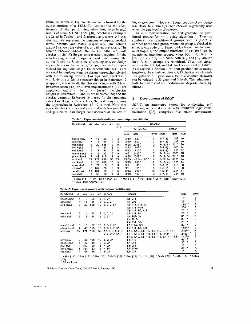
output function partitioning and encoding; state encod- ing; logic synthesis; checker library; and physical synthe- sis. More specifically, the output portion of a sequential
.i 5
.o 1 6
.p 2 2
. s 15 o - - - - t s t a t e l -11- - -1-00-- - - - - 1---- s t a t e l s t a t e 3 -11---boo------ 1---- s t a t e 2 s t a t e 0 -11- - -1-00-- - - - - 1---- s t a t e 3 s t a t e 4 101---Sol------ 1-111 s t a t e 4 s t a t e 1 3 - 1 1 - - - 1 - 0 0 - - - - - - 1-110 s t a t e 4 s t a t e 1 0 -11- - -1-00-- - - - - 1 - 1 0 - s t a t e 4 s t a t e 9 -11- - -1-00-- - - - - 1-011 s t a t e 4 state8 -11-- -1-00-- - - - - 1 - 0 1 0 s t a t e 4 s t a t e 7 - 1 1 - - - 1 - 0 0 - - - - - - 1 - 0 0 1 s t a t e 4 s t a t e 6 -11- - -1-00-- - - - - 1 - 0 0 0 s t a t e 4 s t a t e 5 -11---LOO------ 1---- state5 s t a t e l l 0011--1-00-- - - - - 1---- s t a t e 6 s t a t e 1 4 0 0 1 0 0 - 0 - 0 0 0 0 0 0 1 1 1---- s t a t e 7 s t a t e l l 001-- -1100-- - - - - 1---- s ta te8 s t a t e l l 010-- -1-00-- - - - - 1---- s t a t e 9 s t a t e l l 0 0 1 - - - 1 0 1 0 0 0 0 1 0 1 1---- s t a t e 1 0 s t a t e l l - 1 1 - - - 1 - 0 0 1 0 0 0 0 0 lo--- s t a t e l l s t a t e 1 3 -11---COO------ 11--- s t a t e l l s t a t e 1 2 -11---1-00------ 1---- s t a t e 1 2 s t a t e 1 3 - 1 1 0 1 1 0 - 0 0 - - - - - - 1---- s t a t e 1 3 s t a t e l l -11- - -1-00-- - - - - 1---- s t a t e l l s t a t e 3 - 1 1 0 1 1 0 - 0 0 - - - - - -
a
assigner is developed to assign m/n codes for states. To make the next state function unate, the present states are modified by changing 0 to ‘don’t care’. For example, if
Fig. 2 Synthesis example 4 rnarkl.kiss2 b Encoded format c Physical layout
circuit is first partitioned into a number of subgroups using the output partitioning algorithm described in the previous section. Each subgroup is encoded individually. Most of subgroups are encoded in l / n codes while the remaining one(s) in either Berger codes or m/n codes depending upon whichever provides an optimal solution. In this system, two options, area-optimum and time- optimum, are provided. A state encoding program
52
the present state is assigned as (00101), it is modified as (--1-1). Assigner allows users to assign states randomly or sequentially. The functional circuit is realised with multilevel logic and optimised by using sis [ I l l with algebraic decomposition to keep the output functions and the next state functions unate. The optimised network is then mapped to a cell library containing only AND/OR gates using the technology mapper in sis.
IEE Proc.-Comput. Digit. Tech., Vol. 142, No. I , January 1995
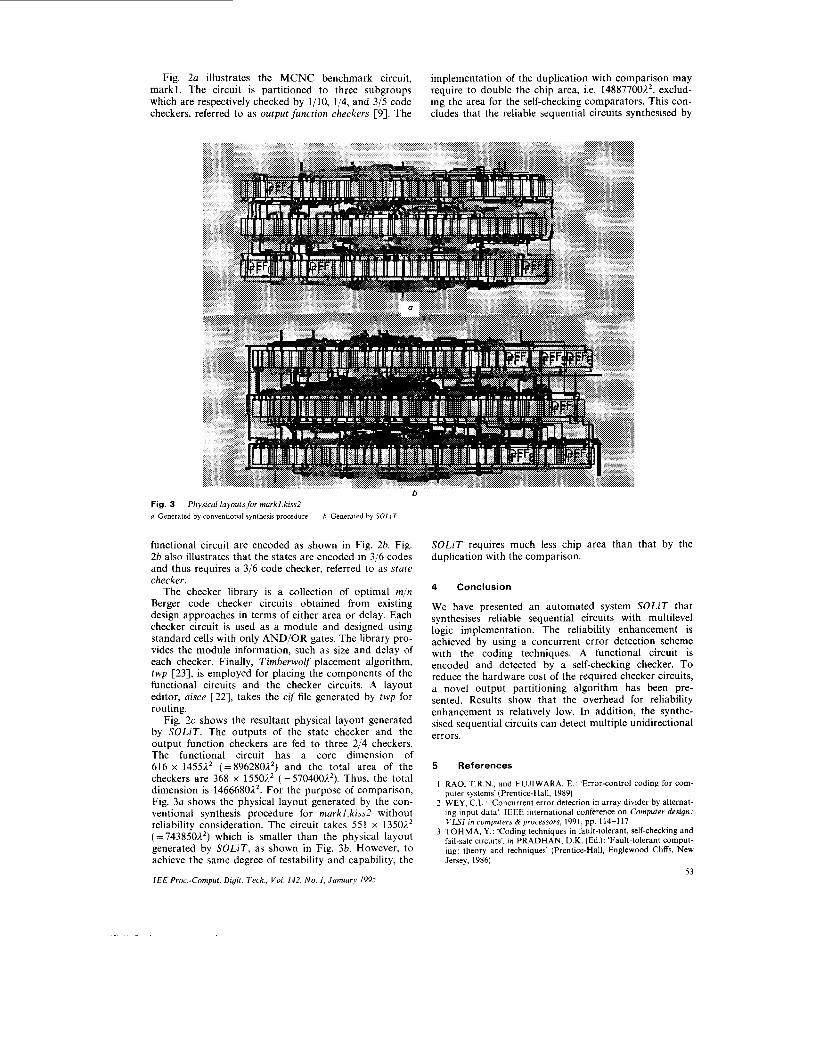
Fig. 2a illustrates the MCNC benchmark circuit, implementation of the duplication with comparison may require to double the chip area, i.e. 148877001’, exclud- ing the area for the self-checking comparators. This con- cludes that the reliable sequential circuits synthesised by
markl. The circuit is partitioned to three subgroups which are respectively checked by 1/10, 1/4, and 3/5 code checkers, referred to as output function checkers [SI. The
Fig. 3 a Generated by conventional synthesis procedure
Physical layouts for markl.kiss2 h Generated by SOLiT
functional circuit are encoded as shown in Fig. 26. Fig. 2b also illustrates that the states are encoded in 3/6 codes and thus requires a 3/6 code checker, referred to as state checker.
The checker library is a collection of optimal m/n Berger code checker circuits obtained from existing design approaches in terms of either area or delay. Each checker circuit is used as a module and designed using standard cells with only AND/OR gates. The library pro- vides the module information, such as size and delay of each checker. Finally, Timberwolf placement algorithm, twp [23], is employed for placing the components of the functional circuits and the checker circuits. A layout editor, aisce 1221, takes the cif file generated by twp for routing.
Fig. 2c shows the resultant physical layout generated by SOLiT. The outputs of the state checker and the output function checkers are fed to three 2/4 checkers. The functional circuit has a core dimension of 616 x 14551’ (=8962801’) and the total area of the checkers are 368 x 15501’ (=570400%2). Thus, the total dimension is 14666802’. For the purpose of comparison, Fig. 3a shows the physical layout generated by the con- ventional synthesis procedure for markl.kiss2 without reliability consideration. The circuit takes 551 x 13502’ ( = 7438501.*) which is smaller than the physical layout generated by SOLiT, as shown in Fig. 3b. However, to achieve the same degree of testability and capability, the
I E E Proc.-Comput. Digit. Tech., Vol. 142, No. I , Januury 1995
SOLiT requires much less chip area than that by the duplication with the comparison.
4 Conclusion
We have presented an automated system SOLiT that synthesises reliable sequential circuits with multilevel logic implementation. The reliability enhancement is achieved by using a concurrent error detection scheme with the coding techniques. A functional circuit is encoded and detected by a self-checking checker. To reduce the hardware cost of the required checker circuits, a novel output partitioning algorithm has been pre- sented. Results show that the overhead for reliability enhancement is relatively low. In addition, the synthe- sised sequential circuits can detect multiple unidirectional errors.
5 References
1 RAO, T.R.N., and FUJIWARA, E.: ‘Error-control coding for com- puter systems’ (Prentice-Hall, 1989)
2 WEY, C.L.: ’Concurrent error detection in array divider by alternat- ing input data‘. IEEE international conference on Computer design: VLSI in computers & processors, 1991, pp. 114-117
3 TOHMA, Y.: ‘Coding techniques in fault-tolerant, self-checking and fail-safe circuits’, in PRADHAN. D.K. (Ed.): ‘Fault-tolerant comput- ing: theory and techniques’ (Prentice-Hall, Englewood Cliffs, New Jersey, 19x6)
53
4 DIAZ, M.: ‘Design of totally self-checking and fail-safe sequential machines’. Proceedings of symposium on Fault tolerant computing, 1977, pp. 124-129
5 OZGUNER, F.: ‘Design of totally self-checking asynchronous sequential machines’. Proceedings of Symposium on Fault tolerant - . - computing, 1977, pp. 124-129
6 VIAUD, J., and DAVID, R.: ‘Sequential self-checking circuits’. Pro- ceedings of symposium on Fault tolerant computing, 1980, pp. 263- 268
7 DE, K., WU, C., and BANERJEE, P.: ‘Reliability driven logic syn- thesis of multilevel circuits’. International symposium on Circuits and systems, May 1992, pp. 1105-1108
8 JHA, N.K., and WANG, S.-J.: ‘Design and synthesis of self-checking VLSI circuits and systems’. IEEE international conference on Com- puter design: VLSI in computers & processors, 1991, pp. 578-581
9 LAI, C.S., and WEY, C.L.: ‘An eflicient output function partitioning algorithm for reducing hardware overhead in self-checking circuits and systems’. Proceedings of 35th midwest symposium on Circuits and systems, Washington, D.C., 1992, pp. 1538-1541
10 MCNC Benchmark Circuits. Presented at International workshop on Logic synthesis, May 1987
1 1 Octtools distribution 3.0, Electrical Research Laboratory, Uni- versity of California, Berkeley, CA, volume 3, 1989
12 PIESTRAK, S.J.: ‘Design of self-testing checkers for I-out-of-n codes’. Proceedings of international conference on Fault-tolerant system diagnostics, Brno, Czechoslovakia, 1983, pp. 57-63
13 ANDERSON, D.A., and METZE, G.: ‘Design of totally self- checking check circuits for m-out-of-n codes’, IEEE Trans., March 1973, C-22, pp. 263-269
14 NANYA, T., and TOHMA, Y.: ‘A 3-level realization of totally self- checking checkers for m-out-of-n codes’. Proceedings of symposium on Fault tolerant computing, 1983, pp. 173-176
15 HALATSIS, C., GAITANIS, N., and SIGALA, M.: ‘Fast and efli- cient totally self-checking checkers for m-out-of-(2m f 1) codes’, IEEE Trans., May 1983, C-32, pp. 507-511
16 MAROUF, M.A., and FRIEDMAN, A.D.: ‘Design of self-checking checkers for Berger codes’. Proceedings of symposium on Fault tol- erant computing, 1978, pp. 179-184
17 ASHJAEE, M.J., and REDDY, S.M.: “Totally self-checking checkers for a class of separable codes’. 12th Allerton conference on Circuits and systems, 1974, pp. 238-242
I8 LO, J.-C., and THANAWASTIEN, S.: ‘The design of fast totally sekhecking Berger code checkers based on Bergex code partition- ing’. Proceedings of symposium on Fault tolerant computing, 1988, pp. 226-231
19 PIESTRAK, S.J.: ‘Design of fast self-testing checkers for a class of Berger codes’, IEEE Trans., 1987, C-36, pp. 629-634
20 PIESTRAK, S.J.: ‘Design of self-testing checkers for m-out-of-n codes’. Proceedings of symposium on Fault tolerant computing, 1983, pp. 173-176
21 MAROUF, M.A., and FRIEDMAN, A.D.: ‘Eflicient design of self- checking checkers for any m-out-of-n codes’, IEEE Trans., June 1978, C-27, pp. 482-490
22 LAI, C.S.: ‘Design and synthesis of on-line testable sequential cir- cuits’. PhD disertation, Michigan State University, August 1993
23 SECHEN, C., and SANGIOVANNI-VINCENTELLI, A.: ‘The Timberwolf placement and routing package’, IEEE J . Solid-state Circuits, April 1985, C-U), pp. 510-522
54 IEE Proc.-Comput. Digit. Tech., Vol. 142, No. I , January 1995