3-2010 SOLUS-500 EXTRACTOR 120V INFORMATION & OPERATING INSTRUCTIONS DO NOT OPERATE MACHINE UNTIL YOU HAVE READ ALL SECTIONS OF THIS INSTRUCTIONS IMPROPER USE OF THE MACHINE WILL VOID THE WARRANTY 1. Always use a defoamer when foaming occurs to prevent vacuum motor damage. 2. Keep machine from rain and snow, extremes in temperatures, and store in a heated location. DO NOT let the machine or the wand freeze. Do not use outdoors. 3. Do not let the pump run dry. 4. Use approved chemicals only. NO SOLVENTS. 5. Wear gloves or use rags when removing quick disconnects to prevent burns. 6. Never use water above 130 ºF/54 ºC in the solution tank. 56041969
Transcript
1 3-2010
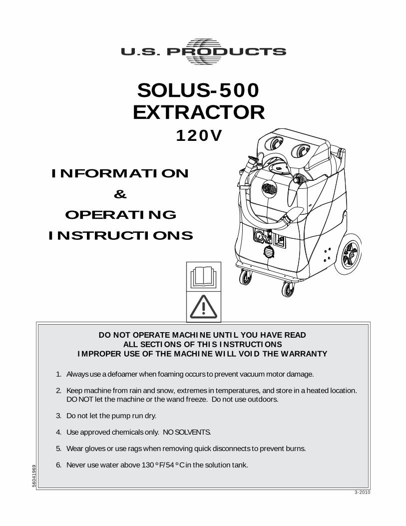
SOLUS-500EXTRACTOR
120V
INFORMATION
&
OPERATING
INSTRUCTIONS
DO NOT OPERATE MACHINE UNTIL YOU HAVE READALL SECTIONS OF THIS INSTRUCTIONS
IMPROPER USE OF THE MACHINE WILL VOID THE WARRANTY
1. Always use a defoamer when foaming occurs to prevent vacuum motor damage.
2. Keep machine from rain and snow, extremes in temperatures, and store in a heated location.DO NOT let the machine or the wand freeze. Do not use outdoors.
3. Do not let the pump run dry.
4. Use approved chemicals only. NO SOLVENTS.
5. Wear gloves or use rags when removing quick disconnects to prevent burns.
6. Never use water above 130 ºF/54 ºC in the solution tank.
56
04
19
69
2
IMPORTANT SAFETY INSTRUCTIONS
This machine is only suitable for commercial use, for example in hotels, schools, hospitals, factories, shopsand offices other than normal residential housekeeping purposes.
When using any electrical appliance, basic precautions should always be followed, including the following:
NOTE: Read all instructions before using this machine.
WARNING!
To reduce the risk of fire, electric shock, or injury:
• Do not leave the machine unattended when it is plugged in. Unplug the unit from the outlet when notin use and before servicing.
• To avoid electric shock, do not expose to rain or snow. Store, and use, indoors.
• Do not allow to be used as a toy. Close attention is necessary when used near children.
• Use only as described in this manual. Use only the manufacturer’s recommended attachments.
• Never add water over 130º F/54º C to the solution tank.
• Do not use with damaged cord or plug. If the machine is not working as it should, has been dropped,damaged, left outdoors or dropped into water, return it to a service center.
• Do not pull by the cord, use the cord as a handle, close a door on the cord, or pull the cord around sharpedges or corners. Do not run the machine over the cord. Keep the cord away from heated surfaces.To unplug, grasp the plug, not the cord.
• Do not handle the plug, the cord or the machine with wet hands.
• Extension cords must be 12/3 and no longer than 50 feet. Replace the cord or unplug immediately ifthe ground prong becomes damaged.
• Do not put any object into openings. Do not use with any opening blocked; keep free of dust, lint, hair,and anything that may reduce air flow.
• Keep loose clothing, hair, fingers, and all parts of body away from openings and moving parts.
• Do not pick up anything that is burning or smoking, such as cigarettes, matches, or hot ashes, or anyhealth endangering dusts. Do not use to pick up flammable or combustible liquids such as gasoline oruse in areas where they may be present.
• Turn off all controls before unplugging.
• Use extra care when cleaning on stairs.
• Connect to a properly grounded outlet only.
• Liquid ejected at the spray nozzle could be dangerous as a result of its temperature, pressure, orchemical content.
3
INSPECTION:Carefully unpack and inspect your SOLUS-500 for shipping damage. Each machine is tested andinspected before shipping. Any shipping damage incurred is the responsibility of the carrier. You shouldnotify the carrier immediately if you notice damage to the box or to the machine or parts.
CLEANING SOLUTIONS:We recommend liquid cleaning chemicals. Powder chemicals may be used, but unless mixed verythoroughly they could cause a build-up in the pump, lines, heat exchanger and/or quick disconnects. Anyproblem caused by a chemical build-up is not covered by warranty. Use a neutral cleaner with a pHbetween 5 and 10 to avoid premature wear of the pump, seals, and/or other components. Damagecaused by the use of strong chemicals is not covered by the warranty.
MAINTENANCE:For optimum performance flush the machine with clear water at the end of each working day. Once amonth, minimum, run a flushing compound through the machine to break up any mineral or chemicalbuild-up that may have formed. The vacuum motor, pump motor, and the pump do not require anyscheduled maintenance; however, the motors may require replacement brushes after 1000 - 1500 hours,and the pump and bypass valve may require rebuild kits after 1000 - 1500 hours, typically (refer tomachine part list for numbers). Clean the body with an all-purpose detergent, and protect it with anautomobile interior polish. Lubricate the wheels, castors, and quick disconnects with an all purposesilicone spray.
PARTS AND SERVICE:Repairs, when required, should be performed by your authorized distributor who maintains an inventoryof original replacement parts and accessories. Call the distributor from whom you purchased thismachine if you need parts and service. Be sure to specify the machine model. Have your serial numberhandy.
(and be sure to register your purchase to activate your warranty)
Serial Number: __________________
Model: SOLUS-500-B
Purchase Date:_____________Write the name and phone number of yourdistributor:
_____________________________________
_____________________________________
4
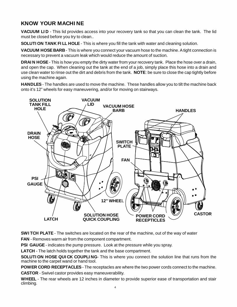
KNOW YOUR MACHINEVACUUM LID - This lid provides access into your recovery tank so that you can clean the tank. The lidmust be closed before you try to clean..
SOLUTION TANK FILL HOLE - This is where you fill the tank with water and cleaning solution.
VACUUM HOSE BARB - This is where you connect your vacuum hose to the machine. A tight connection isnecessary to prevent a vacuum leak which would reduce the amount of suction.
DRAIN HOSE - This is how you empty the dirty water from your recovery tank. Place the hose over a drain,and open the cap. When cleaning out the tank at the end of a job, simply place this hose into a drain anduse clean water to rinse out the dirt and debris from the tank. NOTE: be sure to close the cap tightly beforeusing the machine again.
HANDLES - The handles are used to move the machine. These handles allow you to tilt the machine backonto it’s 12” wheels for easy maneuvering, and/or for moving on stairways.
DRAINHOSE
HANDLESVACUUM HOSE
BARB
FAN
VACUUMLID
12” WHEEL
LATCHSOLUTION HOSEQUICK COUPLING
SWITCHPLATE
CASTOR
SOLUTIONTANK FILL
HOLE
PSIGAUGE
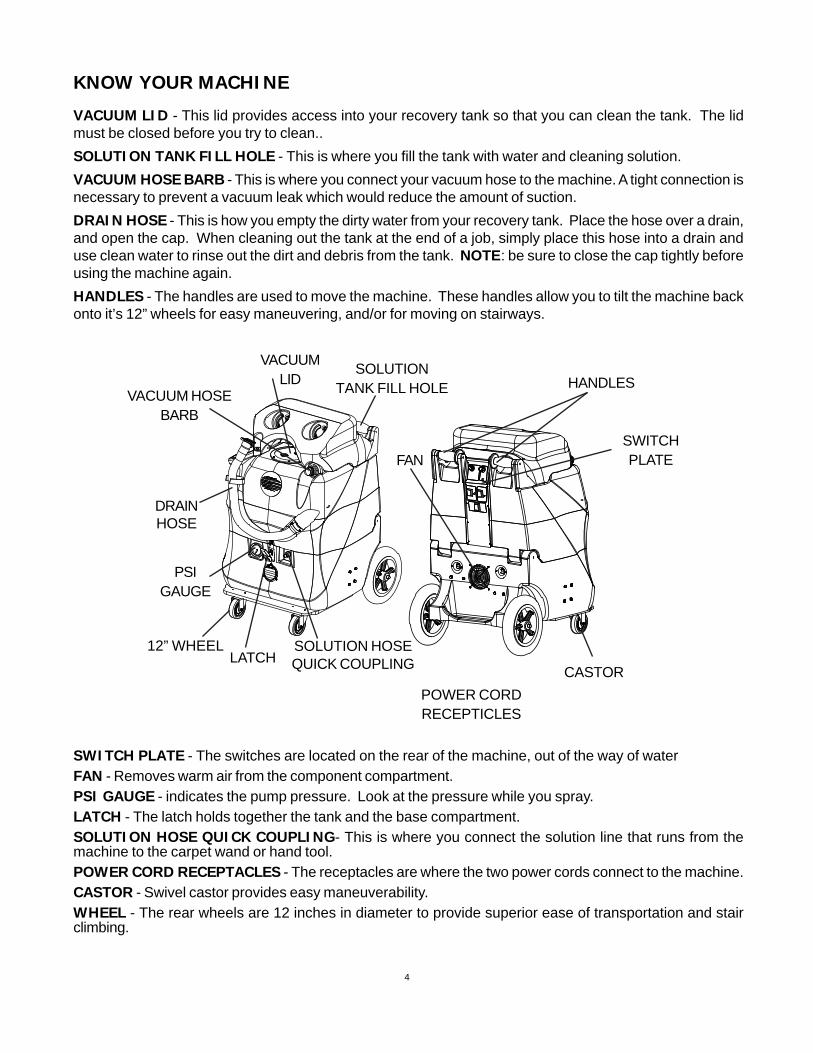
SWITCH PLATE - The switches are located on the rear of the machine, out of the way of waterFAN - Removes warm air from the component compartment.PSI GAUGE - indicates the pump pressure. Look at the pressure while you spray.LATCH - The latch holds together the tank and the base compartment.SOLUTION HOSE QUICK COUPLING- This is where you connect the solution line that runs from themachine to the carpet wand or hand tool.POWER CORD RECEPTACLES - The receptacles are where the two power cords connect to the machine.CASTOR - Swivel castor provides easy maneuverability.WHEEL - The rear wheels are 12 inches in diameter to provide superior ease of transportation and stairclimbing.
POWER CORDRECEPTICLES
5
HEAT CONTROL (1):This dial controls the water temperature.Turn it clockwise to increase watertemperature and counterclockwise todecrease temperature. The heater willoperate only if the circuit locator light (#5)or the bypass switch (#6) is on.
HEAT MODE LIGHT (2):This light will only illuminate when theheater is heating and will turn off when itreaches operating temperature. Duringnormal operation, the “MODE” light will beon most of the time.
PUMP CONTROL (3):This dial controls motor speed and pumppressure. Adjust the dial clockwise toincrease pressure and counterclockwise todecrease pressure or turn off pump. Thepump runs off of cord #1. The pumpspraying pressure will be observable at thepressure gauge.
VACUUM SWITCH (4):This switch will illuminate when the vacuummotors are on. The vacuum motors run offof cord #1.
CIRCUIT LOCATOR (5):When this light is on, it indicates that cord#2 (Identified by the red “H” on the back ofthe extractor.) is on a separate line from cord#1. Cord #2 supplies voltage to the heaterallowing it to heat to the temperature rangeindicated by the Heat Control dial (#1) onthe switch plate.
BYPASS SWITCH (6):The bypass switch will illuminate when it isactivated and will completely bypass thecircuit locator system. Use this system onlywhen the circuit locator light will not turn onand you know each cord is on a separatecircuit.
NEVER LET YOUR MACHINE OR YOUR WAND FREEZE
CAUTION: THE CIRCUIT BREAKER CAN TRIP IF BOTHCORDS ARE ON THE SAME CIRCUIT AND THE BYPASS(heat) SWITCH IS TURNED ON.
1 3
4
6
2
5
SOLUS-500SWITCH PLATE
SWITCH PLATE
6
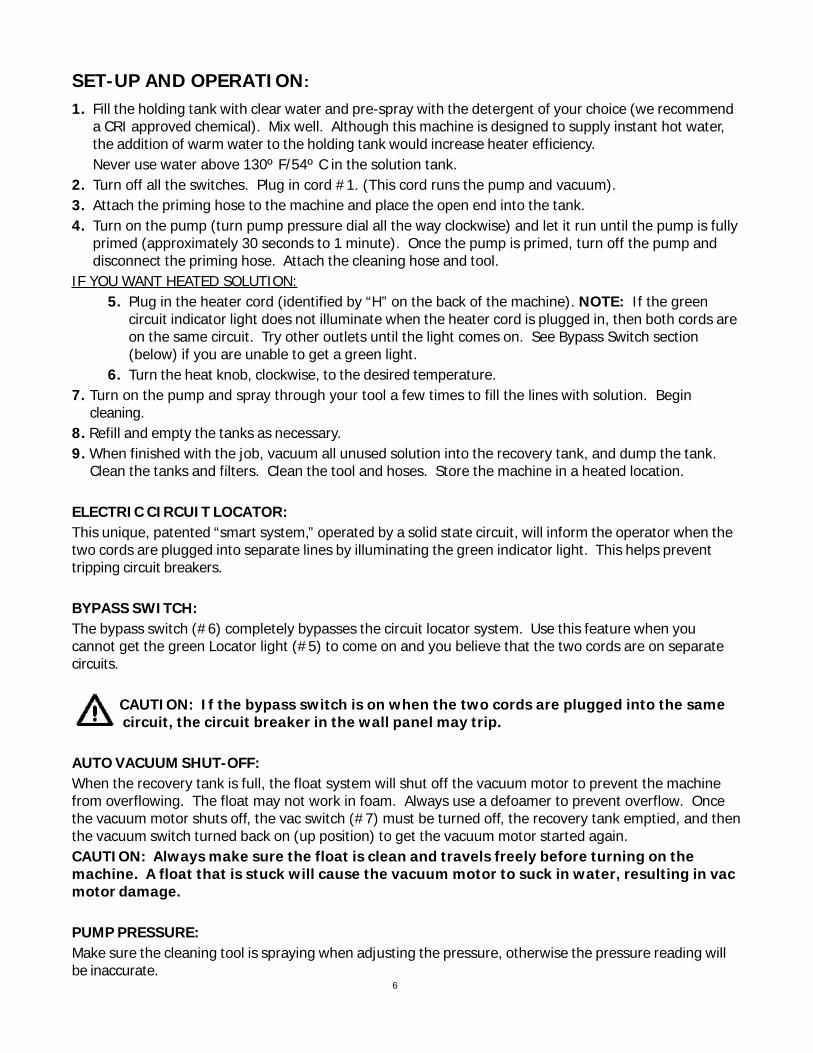
SET-UP AND OPERATION:
1. Fill the holding tank with clear water and pre-spray with the detergent of your choice (we recommenda CRI approved chemical). Mix well. Although this machine is designed to supply instant hot water,the addition of warm water to the holding tank would increase heater efficiency.Never use water above 130º F/54º C in the solution tank.
2. Turn off all the switches. Plug in cord #1. (This cord runs the pump and vacuum).3. Attach the priming hose to the machine and place the open end into the tank.4. Turn on the pump (turn pump pressure dial all the way clockwise) and let it run until the pump is fully
primed (approximately 30 seconds to 1 minute). Once the pump is primed, turn off the pump anddisconnect the priming hose. Attach the cleaning hose and tool.
IF YOU WANT HEATED SOLUTION:5. Plug in the heater cord (identified by “H” on the back of the machine). NOTE: If the green
circuit indicator light does not illuminate when the heater cord is plugged in, then both cords areon the same circuit. Try other outlets until the light comes on. See Bypass Switch section(below) if you are unable to get a green light.
6. Turn the heat knob, clockwise, to the desired temperature.7. Turn on the pump and spray through your tool a few times to fill the lines with solution. Begin
cleaning.8. Refill and empty the tanks as necessary.9. When finished with the job, vacuum all unused solution into the recovery tank, and dump the tank.
Clean the tanks and filters. Clean the tool and hoses. Store the machine in a heated location.
ELECTRIC CIRCUIT LOCATOR:This unique, patented “smart system,” operated by a solid state circuit, will inform the operator when thetwo cords are plugged into separate lines by illuminating the green indicator light. This helps preventtripping circuit breakers.
BYPASS SWITCH:The bypass switch (#6) completely bypasses the circuit locator system. Use this feature when youcannot get the green Locator light (#5) to come on and you believe that the two cords are on separatecircuits.
CAUTION: If the bypass switch is on when the two cords are plugged into the samecircuit, the circuit breaker in the wall panel may trip.
AUTO VACUUM SHUT-OFF:When the recovery tank is full, the float system will shut off the vacuum motor to prevent the machinefrom overflowing. The float may not work in foam. Always use a defoamer to prevent overflow. Oncethe vacuum motor shuts off, the vac switch (#7) must be turned off, the recovery tank emptied, and thenthe vacuum switch turned back on (up position) to get the vacuum motor started again.CAUTION: Always make sure the float is clean and travels freely before turning on themachine. A float that is stuck will cause the vacuum motor to suck in water, resulting in vacmotor damage.
PUMP PRESSURE:Make sure the cleaning tool is spraying when adjusting the pressure, otherwise the pressure reading willbe inaccurate.
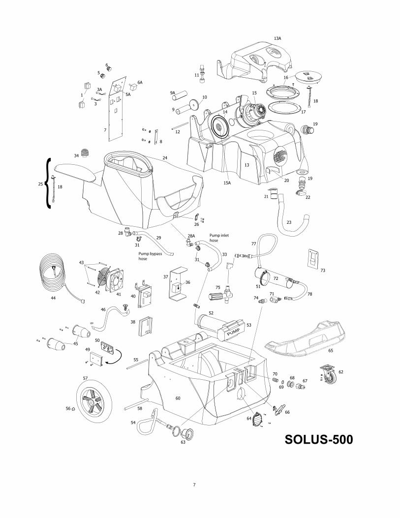
*FP194E Heat repair kit includes thermistorcontrol, thermistor probe & cutout
950CP Pump rebuild kit, valves and o-rings250 Pump rebuild kit, piston and seals950D Cam/bearing, pump driveFP619 Bag, pre-filter for recovery inlet
120V
ITEM PART No DESCRIPTION
parts in kits are not sold separately
9
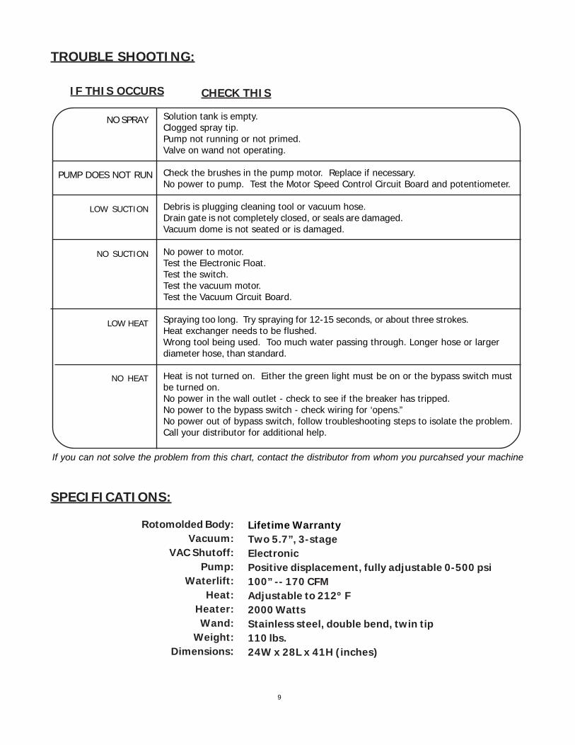
SPECIFICATIONS:
Rotomolded Body:Vacuum:
VAC Shutoff:Pump:
Waterlift:Heat:
Heater:Wand:
Weight:Dimensions:
Lifetime WarrantyTwo 5.7”, 3-stageElectronicPositive displacement, fully adjustable 0-500 psi100” -- 170 CFMAdjustable to 212º F2000 WattsStainless steel, double bend, twin tip110 lbs.24W x 28L x 41H (inches)
TROUBLE SHOOTING:
IF THIS OCCURS CHECK THIS
NO SPRAY
PUMP DOES NOT RUN
Solution tank is empty.Clogged spray tip.Pump not running or not primed.Valve on wand not operating.
Check the brushes in the pump motor. Replace if necessary.No power to pump. Test the Motor Speed Control Circuit Board and potentiometer.
Debris is plugging cleaning tool or vacuum hose.Drain gate is not completely closed, or seals are damaged.Vacuum dome is not seated or is damaged.
No power to motor.Test the Electronic Float.Test the switch.Test the vacuum motor.Test the Vacuum Circuit Board.
Spraying too long. Try spraying for 12-15 seconds, or about three strokes.Heat exchanger needs to be flushed.Wrong tool being used. Too much water passing through. Longer hose or largerdiameter hose, than standard.
Heat is not turned on. Either the green light must be on or the bypass switch mustbe turned on.No power in the wall outlet - check to see if the breaker has tripped.No power to the bypass switch - check wiring for ‘opens.”No power out of bypass switch, follow troubleshooting steps to isolate the problem.Call your distributor for additional help.
LOW SUCTION
NO SUCTION
LOW HEAT
NO HEAT
If you can not solve the problem from this chart, contact the distributor from whom you purcahsed your machine
10
NOTES:
SOLUS-500EXTRACTOR
120V
1
5-2010
DO NOT OPERATE MACHINE UNTIL YOU HAVE READ
ALL SECTIONS OF THIS INSTRUCTIONS
IMPROPER USE OF THE MACHINE WILL VOID THE WARRANTY
1. Always use a defoamer when foaming occurs to prevent vacuum motor damage.
2. Keep machine from rain and snow, extremes in temperatures, and store in aheated location. DO NOT let the machine or wand freeze. Do not use outdoors.
3. Do not let the pump run dry.
4. Use approved chemicals only. NO SOLVENTS.
5. Wear gloves or use rags when removing quick disconnects to prevent burns.
6. Never use water above 130 ºF/54 ºC in the solution tank.
SOLUS-500REXTRACTOR
120V
INFORMATION
&
OPERATING
INSTRUCTIONS
NEVER LET YOUR MACHINE OR YOUR WAND FREEZE
56
04
19
70
2
IMPORTANT SAFETY INSTRUCTIONS
This machine is only suitable for commercial use, for example in hotels, schools, hospitals, factories, shopsand offices other than normal residential housekeeping purposes.
When using any electrical appliance, basic precautions should always be followed, including the following:
NOTE: Read all instructions before using this machine.
WARNING!
To reduce the risk of fire, electric shock, or injury:
• Do not leave the machine unattended when it is plugged in. Unplug the unit from the outlet whennot in use and before servicing.
• To avoid electric shock, do not expose to rain or snow. Store, and use, indoors.
• Do not allow to be used as a toy. Close attention is necessary when used near children.
• Use only as described in this manual. Use only the manufacturer’s recommended attachments.
• Never add water over 130º F/54º C to the solution tank.
• Do not use with damaged cord or plug. If the machine is not working as it should, has beendropped, damaged, left outdoors or dropped into water, return it to a service center.
• Do not pull by the cord, use the cord as a handle, close a door on the cord, or pull the cord aroundsharp edges or corners. Do not run the machine over the cord. Keep the cord away from heatedsurfaces. To unplug, grasp the plug, not the cord.
• Do not handle the plug, the cord or the machine with wet hands.
• Extension cords must be 12/3 and no longer than 50 feet. Replace the cord or unplug immediatelyif the ground prong becomes damaged.
• Do not put any object into openings. Do not use with any opening blocked; keep free of dust, lint,hair, and anything that may reduce air flow.
• Keep loose clothing, hair, fingers, and all parts of body away from openings and moving parts.
• Do not pick up anything that is burning or smoking, such as cigarettes, matches, or hot ashes, or anyhealth endangering dusts. Do not use to pick up flammable or combustible liquids such as gasolineor use in areas where they may be present.
• Turn off all controls before unplugging.
• Use extra care when cleaning on stairs.
• Connect to a properly grounded outlet only.
• Liquid ejected at the spray nozzle could be dangerous as a result of its temperature, pressure,orchemical content.
• Never turn your pump on without a tool or the priming hose connected.
3
INSPECTION:Carefully unpack and inspect your SOLUS-500R for shipping damage. Each machine is tested andinspected before shipping. Any shipping damage incurred is the responsibility of the carrier. You shouldnotify the carrier immediately if you notice damage to the box or to the machine or parts.
CLEANING SOLUTIONS:We recommend liquid cleaning chemicals. Powder chemicals may be used, but unless mixed verythoroughly they could cause a build-up in the pump, lines, heat exchanger and/or quick disconnects. Anyproblem caused by a chemical build-up is not covered by warranty. Use a neutral cleaner with a pHbetween 5 and 10 to avoid premature wear of the pump, seals, and/or other components. Damagecaused by the use of strong chemicals is not covered by the warranty.
MAINTENANCE:For optimum performance flush the machine with clear water at the end of each working day. Once amonth, minimum, run a flushing compound through the machine to break up any mineral or chemicalbuild-up that may have formed. The vacuum motor, pump motor, and the pump do not require anyscheduled maintenance; however, the motors may require replacement brushes after 1000 - 1500 hours,and the pump and bypass valve may require rebuild kits after 1000 - 1500 hours, typically (refer tomachine part list for numbers). Clean the body with an all-purpose detergent, and protect it with anautomobile interior polish. Lubricate the wheels, castors, and quick disconnects with an all purposesilicone spray.
PARTS AND SERVICE:Repairs, when required, should be performed by your authorized distributor who maintains an inventoryof original replacement parts and accessories. Call the distributor from whom you purchased thismachine if you need parts and service. Be sure to specify the machine model. Have your serial numberhandy.
(and be sure to register your purchase to activate your warranty)
Serial Number: __________________
Model: SOLUS-500R
Purchase Date:_____________
Write the name and phone number of your distributor:
_____________________________________
_____________________________________
4
KNOW YOUR MACHINE
VACUUM LID - This lid provides access into your recovery tank so that you can clean the tank. The lidmust be closed before you try to clean..
SOLUTION TANK FILL HOLE - This is where you fill the tank with water and cleaning solution.
VACUUM HOSE BARB - This is where you connect your vacuum hose to the machine. A tight connection isnecessary to prevent a vacuum leak which would reduce the amount of suction.
DRAIN HOSE - This is how you empty the dirty water from your recovery tank. Place the hose over a drain,and open the cap. When cleaning out the tank at the end of a job, simply place this hose into a drain anduse clean water to rinse out the dirt and debris from the tank. NOTE: be sure to close the cap tightly beforeusing the machine again.
HANDLES - The handles are used to move the machine. These handles allow you to tilt the machine backonto it’s 12” wheels for easy maneuvering, and/or for moving on stairways.
SWITCH PLATE - The switches are located on the rear of the machine, out of the way of waterFAN - Removes warm air from the component compartment.PSI GAUGE - indicates the pump pressure. Look at the pressure while you spray.LATCH - The latch holds together the tank and the base compartment.SOLUTION HOSE QUICK COUPLING- This is where you connect the solution line that runs from themachine to the carpet wand or hand tool.POWER CORD RECEPTACLES - The receptacles are where the two power cords connect to the machine.CASTOR - Swivel castor provides easy maneuverability.WHEEL - The rear wheels are 12 inches in diameter to provide superior ease of transportation and stairclimbing.
DRAINHOSE
HANDLESVACUUM HOSE
BARB
FAN
POWER CORDRECEPTICLES
VACUUMLID
LATCHSOLUTION HOSEQUICK COUPLING
SWITCHPLATE
CASTOR
SOLUTIONTANK FILL HOLE
PSIGAUGE
12” WHEEL
5
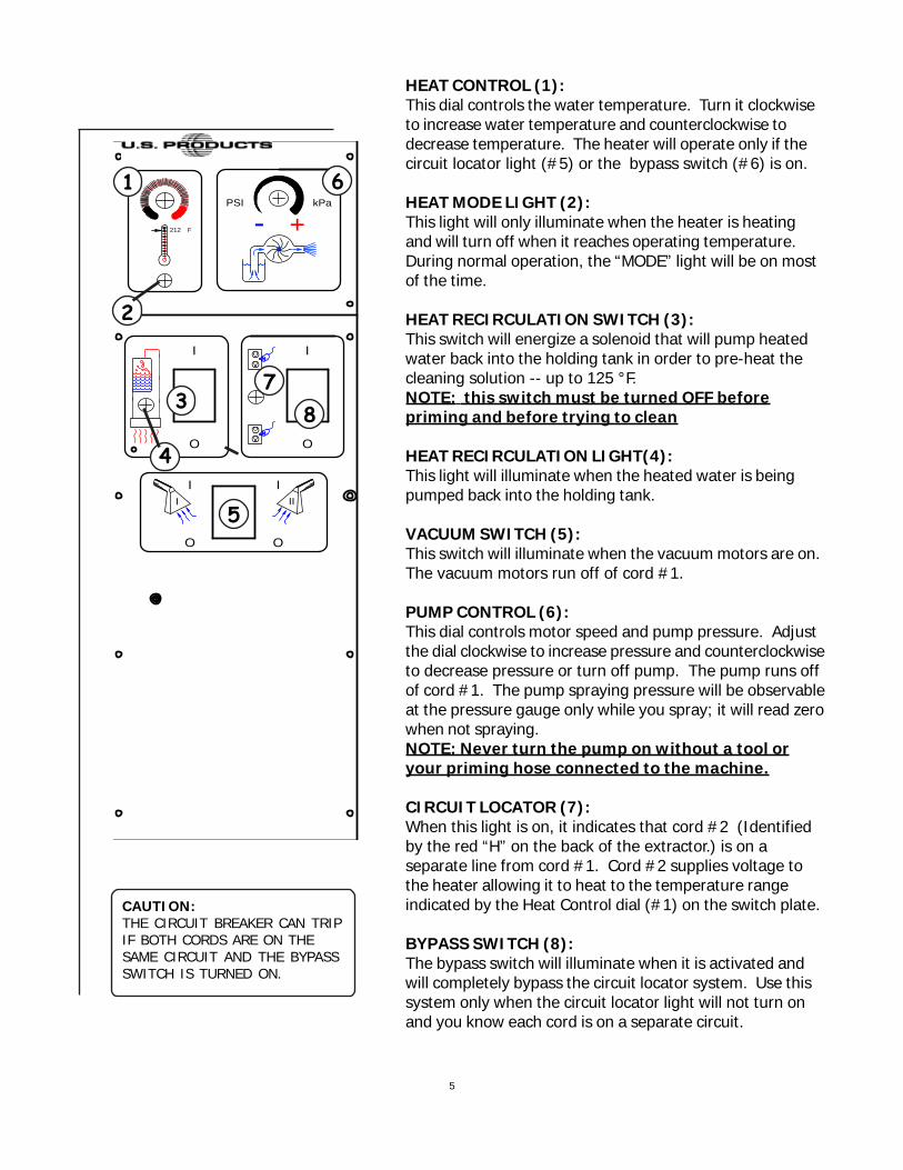
HEAT CONTROL (1):This dial controls the water temperature. Turn it clockwiseto increase water temperature and counterclockwise todecrease temperature. The heater will operate only if thecircuit locator light (#5) or the bypass switch (#6) is on.
HEAT MODE LIGHT (2):This light will only illuminate when the heater is heatingand will turn off when it reaches operating temperature.During normal operation, the “MODE” light will be on mostof the time.
HEAT RECIRCULATION SWITCH (3):This switch will energize a solenoid that will pump heatedwater back into the holding tank in order to pre-heat thecleaning solution -- up to 125 °F.NOTE: this switch must be turned OFF beforepriming and before trying to clean
HEAT RECIRCULATION LIGHT(4):This light will illuminate when the heated water is beingpumped back into the holding tank.
VACUUM SWITCH (5):This switch will illuminate when the vacuum motors are on.The vacuum motors run off of cord #1.
PUMP CONTROL (6):This dial controls motor speed and pump pressure. Adjustthe dial clockwise to increase pressure and counterclockwiseto decrease pressure or turn off pump. The pump runs offof cord #1. The pump spraying pressure will be observableat the pressure gauge only while you spray; it will read zerowhen not spraying.NOTE: Never turn the pump on without a tool oryour priming hose connected to the machine.
CIRCUIT LOCATOR (7):When this light is on, it indicates that cord #2 (Identifiedby the red “H” on the back of the extractor.) is on aseparate line from cord #1. Cord #2 supplies voltage tothe heater allowing it to heat to the temperature rangeindicated by the Heat Control dial (#1) on the switch plate.
BYPASS SWITCH (8):The bypass switch will illuminate when it is activated andwill completely bypass the circuit locator system. Use thissystem only when the circuit locator light will not turn onand you know each cord is on a separate circuit.
CAUTION:THE CIRCUIT BREAKER CAN TRIPIF BOTH CORDS ARE ON THESAME CIRCUIT AND THE BYPASSSWITCH IS TURNED ON.
- +
I II
I I
O O
O O
I I
kPaPSI
212� F
1
2
37
8
4
5
6
6
SET-UP and OPERATION:
1. Fill the holding tank with clear water and prespray with the detergent of your choice (we recommenda CRI approved chemical). Mix well. Although this machine is designed to supply instant hot water,the addition of warm water to the holding tank would increase heater efficiency. Never use waterabove 130º F/54º C in the solution tank.
2. Turn off all the switches. Plug in cord #1. (This cord runs the pump and vacuum). NOTE: TURNTHE HEAT RECIRCULATION SWITCH OFF BEFORE PRIMING THE PUMP.
3. Attach the priming hose to the machine and place the open end into the tank.
4. Turn on the pump (turn pump pressure dial all the way clockwise) and let it run until the pump is fullyprimed (approximately 30 seconds to 1 minute). Once the pump is primed, turn off the pump anddisconnect the priming hose. Attach the cleaning hose and tool.
IF YOU WANT HEATED SOLUTION:
5. Plug in the heater cord (identified by “H” on the back of the machine). NOTE: If the greencircuit indicator light does not illuminate when the heater cord is plugged in, then both cords areon the same circuit. Try other outlets until the light comes on. See Bypass Switch section(below) if you are unable to get a green light.
6. Turn the heat knob clockwise to the desired temperature.
IF YOU WANT TO PRE-HEAT THE SOLUTION IN THE HOLDING TANK
7. Turn on both the pump and heat recirculation switches. NOTE: this switch will recirculateheated water back to the holding tank, until it reaches 125 °F. At that point, therecirculation will automatically stop. If the temperature of the water in the tank drops below125 °F, and if the recirculation switch is still turned ON, the system will begin to recirculatethe water again until it gets back up to 125 °F. You can choose to let the solution in yourholding tank reach 125° or you can choose to begin cleaning sooner than that.
NOTE: the time that it will take for your solution to reach 125 °F will vary with the temperatureof the solution that you put into the tank, the ambient temperature, the amount of solution inyour tank, etc.
8. Turn on the pump and spray through your tool a few times to fill the lines with solution. Begincleaning.
9. Refill and empty the tanks as necessary.
10. When finished with the job, vacuum all unused solution into the recovery tank, and dump the tank.Clean the tanks and filters. Clean the tool and hoses. Store the machine in a heated location.
ELECTRIC CIRCUIT LOCATOR:This unique, patented “smart system,” operated by a solid state circuit, will inform the operator when thetwo cords are plugged into separate lines by illuminating the green, indicator light. This helps preventtripping circuit breakers.
CONTINUE ON NEXT PAGE
7
YOU MUST TURN THE HEAT RECIRCULATION SWITCH OFFBEFORE YOU CAN PRIME THE PUMP AND BEFORE YOUBEGIN CLEANING, otherwise your pump pressure will bevery low.
BYPASS SWITCH:The bypass switch (#6) completely bypasses the circuit locator system. Use this feature when youcannot get the green Locator light (#5) to come on and you believe that the two cords are on separatecircuits.CAUTION: If the bypass switch is on when the two cords are plugged into the same circuit,the breaker may trip.
AUTO VACUUM SHUT-OFF:When the recovery tank is full, the float system will shut off the vacuum motor to prevent the machinefrom overflowing. The float may not work in foam. Always use a defoamer to prevent overflow. Oncethe vacuum motor shuts off, the vac switch (#7) must be turned off, the recovery tank emptied, and thenthe vacuum switch turned back on (up position) to get the vacuum motor started again.CAUTION: Always make sure the float is clean and travels freely before turning on themachine. A float that is stuck will cause the vacuum motor to suck in water, resulting in vacmotor damage.
PUMP PRESSURE:Make sure the cleaning tool is spraying when adjusting the pressure, otherwise the pressure reading willbe inaccurate.
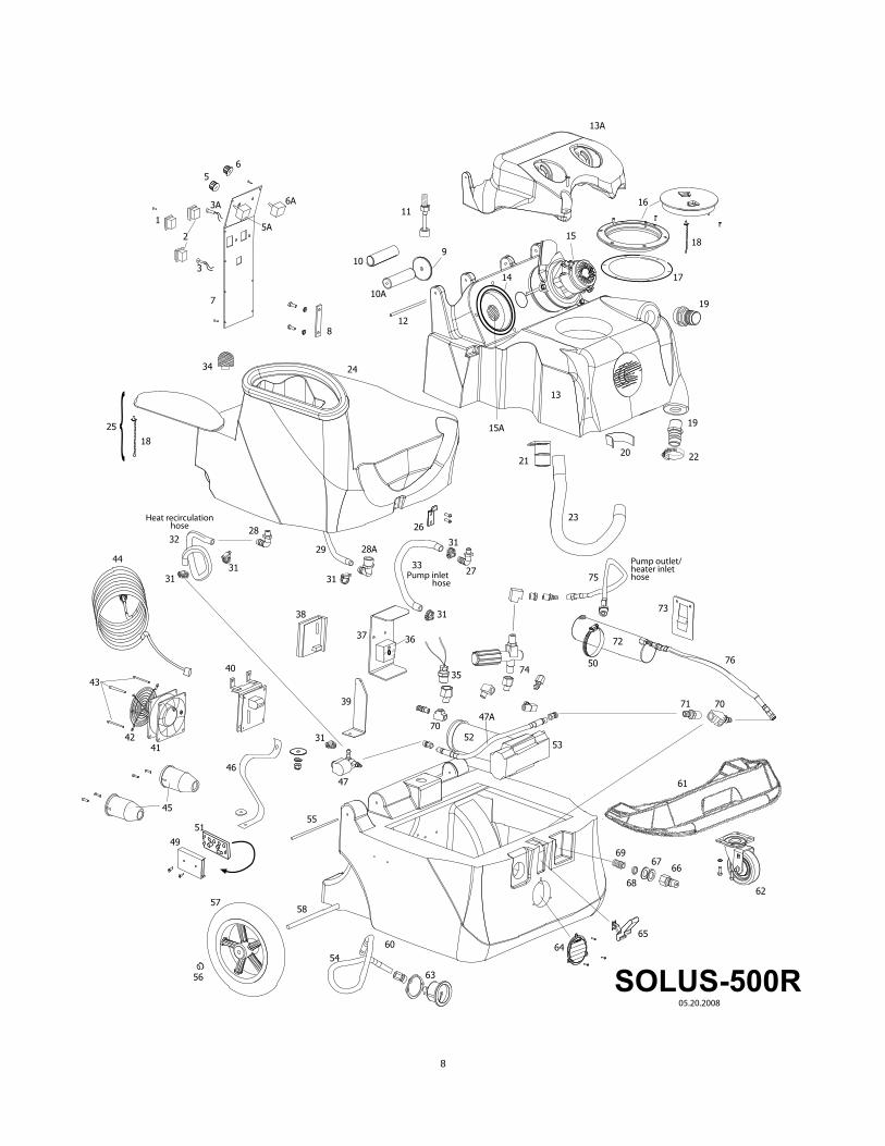
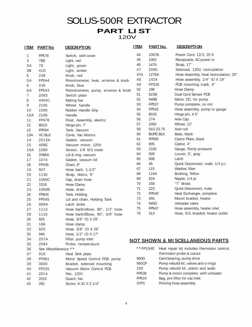
ITEM PART No DESCRIPTION ITEM PART No. DESCRIPTION
120V
NOT SHOWN & MISCELLANEOUS PARTS
**FP194E Heat repair kit includes thermistor control,thermistor probe & cutout
950D Cam/bearing, pump drive950CP Pump rebuild kit, valves and o-rings250 Pump rebuild kit, piston and sealsFP538 Pump & motor complete, with unloaderFP619 Bag, pre-filter for vac inletSYP1 Priming hose assembly
10
SPECIFICATIONS:
Rotomolded Body:Vacuum:
VAC Shutoff:Pump:
Waterlift:Heat:
Heater:Wand:
Weight:Dimensions:
Lifetime WarrantyTwo 5.7”, 3-stageElectronicPositive displacement, fully adjustable 0-500 psi100” -- 170 CFMAdjustable to 212º F2000 WattsStainless steel, double bend, twin tip110 lbs.24W x 28L x 41H (inches)
TROUBLE SHOOTING:
IF THIS OCCURS CHECK THIS
NO SPRAY
PUMP DOES NOT RUN
Solution tank is empty.Clogged spray tip.Pump not running or not primed.Valve on wand not operating.
Check the brushes in the pump motor. Replace if necessary.No power to pump. Test the Motor Speed Control Circuit Board and potentiometer.
Make sure the Heat Recirculation Switch is turned off.
Debris is plugging cleaning tool or vacuum hose.Drain gate is not completely closed, or seals are damaged.Vacuum dome is not seated or is damaged.
No power to motor.Test the Electronic Float.Test the switch.Test the vacuum motor.Test the Vacuum Circuit Board.
Spraying too long. Try spraying for 12-15 seconds, or about three strokes.Heat exchanger needs to be flushed.Wrong tool being used. Too much water passing through. Longer hose or largerdiameter hose, than standard.
Heat is not turned on. Either the green light must be on or the bypass switch mustbe turned on.No power in the wall outlet - check to see if the breaker has tripped.No power to the bypass switch - check wiring for ‘opens.”No power out of bypass switch, follow troubleshooting steps to isolate the problem.Call your distributor for additional help.