CHAPTER 2-1 Ethernet-to-the-Factory 1.2 Design and Implementation Guide OL-14268-01 2 Solution Architecture Overview This chapter provides an overview of the Ethernet-to-the-Factory (EttF) solution architecture, as a means to describe the various systems, components, and their relation to each other to give context to the networking function and technical requirements. EttF is an architecture that provides network and security services to the devices, equipment, and applications found in industrial automation and control systems and integrates them into the wider enterprise network. The networking requirements of a production facility often differ from a typical IT network. This solution architecture overview provides the background and description of an industrial automation and control network model and highlights the differences between the EttF architecture and the IT network infrastructure. Reuse is an objective of any architecture, and this is the case with the EttF solution architecture. Industrial automation and control systems are deployed in a large variety of industries, such as automotive, pharmaceuticals, consumer goods, pulp and paper, oil and gas, and energy. Industrial automation and control systems are also deployed in a wide variety of types of manufacturing, such as batch, discrete, process, and hybrid manufacturing. Size of deployments include small (less than 50 devices), medium (less than 200 devices), and large (from 200 up to 10,000s of devices). This architecture is meant to be a model/structure to be used in all these types of manufacturing environments, but clearly it must be tailored to the industry, type of manufacturing, size, and eventually the customer. Industrial Automation and Control Reference Model To understand the security and network systems requirements of an industrial automation and control systems in a production facility, this guide uses a framework to describe the basic functions and composition of a manufacturing system. The Purdue Model for Control Hierarchy (reference ISBN 1-55617-265-6) is a common and well-understood model in the Manufacturing industry that segments devices and equipment into hierarchical functions. It has been incorporated into many other models and standards in the industry. Based on this segmentation of the production floor technology, the Instrumentation, Systems, and Automation Society (ISA) SP 99 Committee for Manufacturing and Control Systems Security has identified the levels and framework shown in Figure 2-1. Each zone and the related levels are then subsequently described in detail.
Transcript
Ethernet-tOL-14268-01
C H A P T E R 2
Solution Architecture
OverviewThis chapter provides an overview of the Ethernet-to-the-Factory (EttF) solution architecture, as a means to describe the various systems, components, and their relation to each other to give context to the networking function and technical requirements. EttF is an architecture that provides network and security services to the devices, equipment, and applications found in industrial automation and control systems and integrates them into the wider enterprise network. The networking requirements of a production facility often differ from a typical IT network. This solution architecture overview provides the background and description of an industrial automation and control network model and highlights the differences between the EttF architecture and the IT network infrastructure.
Reuse is an objective of any architecture, and this is the case with the EttF solution architecture. Industrial automation and control systems are deployed in a large variety of industries, such as automotive, pharmaceuticals, consumer goods, pulp and paper, oil and gas, and energy. Industrial automation and control systems are also deployed in a wide variety of types of manufacturing, such as batch, discrete, process, and hybrid manufacturing. Size of deployments include small (less than 50 devices), medium (less than 200 devices), and large (from 200 up to 10,000s of devices). This architecture is meant to be a model/structure to be used in all these types of manufacturing environments, but clearly it must be tailored to the industry, type of manufacturing, size, and eventually the customer.
Industrial Automation and Control Reference ModelTo understand the security and network systems requirements of an industrial automation and control systems in a production facility, this guide uses a framework to describe the basic functions and composition of a manufacturing system. The Purdue Model for Control Hierarchy (reference ISBN 1-55617-265-6) is a common and well-understood model in the Manufacturing industry that segments devices and equipment into hierarchical functions. It has been incorporated into many other models and standards in the industry. Based on this segmentation of the production floor technology, the Instrumentation, Systems, and Automation Society (ISA) SP 99 Committee for Manufacturing and Control Systems Security has identified the levels and framework shown in Figure 2-1. Each zone and the related levels are then subsequently described in detail.
2-1o-the-Factory 1.2 Design and Implementation Guide
Chapter 2 Solution Architecture Overview
Figure 2-1 Six Level Plant Architecture
This model identifies “levels” of operations and defines each level. In this document, “levels” generally refer to this concept of levels of operations. The OSI model is also commonly referred to when discussing network architectures. The OSI model refers to “layers” of network communication functions. In this document unless specified, “layers” refer to layers of the OSI model.
Safety Zone
Safety is considered the highest priority function in industrial automation and control systems. Historically, safety subsystems have been hard-wired. More recently, these systems have been implemented with totally dedicated infrastructure to ensure that the industrial automation and control equipment does not pose a threat to people or the environment. These subsystems have specific protocols and networking technologies. In some industries, these subsystems have not shared any resources (power, network, etc) with the rest of the industrial automation and control system with which they work. But because of the reliability and the impact of failure, the adoption of new technologies (for example, Ethernet and IP technologies is slower than in other areas of the production facility). However, there have been enhancements to industrial automation and control networks such as the Open DeviceNet Vendors Association (ODVA) Common Industrial Protocol (CIP) safety solution, where the safety protocol runs on the same network infrastructure as the standard protocol. CIP safety systems on DeviceNet and EtherNet/IP have been successfully developed and installed.
This version of the solution does not consider integration of Safety Zone equipment, although that may be introduced in future versions.
Cell/Area Zone
The cell/area zone is a functional area within a production facility. In an automotive plant, it may be a body shop or a sub-assembly process. In a food and beverage facility, it may be the batch mixing area. It may be as small as a single controller and its associated devices on an assembly line, or multiple controllers on several tanks. Each production facility defines the cell/area zone demarcation differently and to varying degrees of granularity. For the purposes of this architecture, a cell/area zone is a set of
SafetyZone
Enterprise Network
Site Business Planning and Logistics Network
Safety-Critical
EnterpriseZone
ManufacturingZone
Cell/AreaZone
Site Manugacturing Operations and Control
Area Supervisory Control
Basic Control
Process
2209
60
Level 5
Level 4
Level 3
Level 1
Level 0
Level 2
2-2Ethernet-to-the-Factory 1.2 Design and Implementation Guide
OL-14268-01
Chapter 2 Solution Architecture Overview
devices, controllers, etc that are involved in the real-time control of a functional aspect of the manufacturing process. To control the functional process, they are all in real-time communication with each other. Most production facilities have multiple cell/area networks. This zone has essentially three levels of activity occurring, as described in the following sections.
Level 0—Process
Level 0 consists of a wide variety of sensors, actuators and devices involved in the basic manufacturing process. These devices perform the basic functions of the industrial automation and control system, such as driving a motor, measuring variables, setting an output, and performing key functions such as painting, welding, bending, and so on. These functions can be very simple (temperature gauge) to highly complex (a moving robot). See Industrial Automation and Control Devices, page 1-22 for a more detailed explanation.
These devices take direction and communicate status with the control devices in the next level of the model. In addition, other devices or users may need to directly access Level 0 devices to perform maintenance or resolve problems on the devices.
Level 0 devices usually have the following characteristics:
• Drive the real-time, deterministic communication requirements
• Measure the machine variables and control process outputs based on time
• Exist in challenging physical environments that drive topology constraints
• Vary according to the size of the network from a small (10s) to a large (1000s) number of devices
• Once designed and installed, are not replaced all together until the production line is overhauled or replaced, which is typically five or more years
Because historically these requirements have not been met by the Ethernet and TCP/IP technologies, a wide variety of proprietary network protocols has arisen. These protocols often cover Layers 1–7 of the OSI model. Ethernet and TCP/IP are being integrated into their frameworks, but with differing approaches. See Industrial Automation and Control System Communication Protocols, page 1-23 for an overview of these protocols.
Control engineers such as electrical, process, and so on, and not the IT departments, typically design and implement these devices and the networks that support them.
Level 1—Basic Control
Level 1 consists of basic controllers that control and manipulate the manufacturing process which its key function is to interface with the Level 0 devices (I/O, linking devices, bridges, etc). In discrete manufacturing, this is typically a programmable logic controller (PLC). In process manufacturing, the basic controller is referred to as a distributed control system (DCS). For the purposes of this solution architecture, this document uses the terms controller or programmable automation controller (PAC), which refer to the general range of controllers used across manufacturing, both process and discrete.
Most PACs run proprietary operating systems that are programmed and configured from workstations or other advanced control systems. PACs are basically very simple, modular computers that consist of some or all of the following:
• A controller that computes all the data and executes programs loaded onto it
• I/O or network modules that communicate with devices, human-machine interfaces (HMIs), or advanced control systems
• Power modules that deliver power to the rest of the PAC and potentially other devices
2-3Ethernet-to-the-Factory 1.2 Design and Implementation Guide
OL-14268-01
Chapter 2 Solution Architecture Overview
PACs are the brains of the industrial automation and control system, making the basic decisions based on feedback from the devices found at Level 0. PACs act alone or in conjunction with other PACs to manage the devices and thereby the manufacturing process. PACs are programmed via a workstation, and configured and managed via an external device referred to as an HMI, which is considered a Level 2 device. PACs also communicate with information and production control systems (historian, asset manager, manufacturing execution system, production scheduler, etc) in Levels 2 and 3. PACs provide status and data about the actual process being controlled as well as take input for execution (for example, fulfill an order).
Thus, PACs produce network traffic in three directions:
• Downward with the devices in Level 0 that they control and manage
• Peer-to-peer with other PACs to manage the automation and control for a cell/area or production line
• Upward with HMIs and information and production control systems
The PAC performs a hub function in the manufacturing control area. The PAC translates high-level parameters (for example, recipes) into executable orders and manages those parameters throughout the manufacturing process. They also consolidate the I/O traffic from devices and pass data on to the upper-level plant floor functions. In some implementations, the PAC is also the physical network hub for the control network as the only device where connections to Level 0 devices, HMIs, and advanced control systems exist.
PACs must also meet the requirements being driven by the Level 0 devices, as described above.
Level 2 —Area Control
Production facilities are usually laid out in areas or cells where a particular aspect of the manufacturing process occurs. In an automotive plant, this might be a body shop, paint shop, or a general assembly line. In a process solution, it might be a batch mixing area. Level 2 represents the systems and functions associated with the runtime supervision and operation of an area of a production facility. These include the following:
• Operator interfaces or HMIs
• Alarms or alerting systems
• Process historian batch management systems
• Control room workstations
Depending on the size or structure of a facility, these functions may exist at the site level (Level 3). These systems communicate with the PACs in Level 1 and interface or share data with the site or enterprise (Level 4/5) systems and applications. These systems are primarily based on standard computing equipment and operating systems (Unix-based or Microsoft Windows). For this reason, these systems are more likely to communicate with standard networking protocols (Ethernet and TCP/IP). Additionally, because these systems tend to be more aligned with standard IT technologies, they may also be implemented and supported by IT-skilled personnel, although typically they are implemented by the manufacturing organization. These people may or may not belong organizationally to IT.
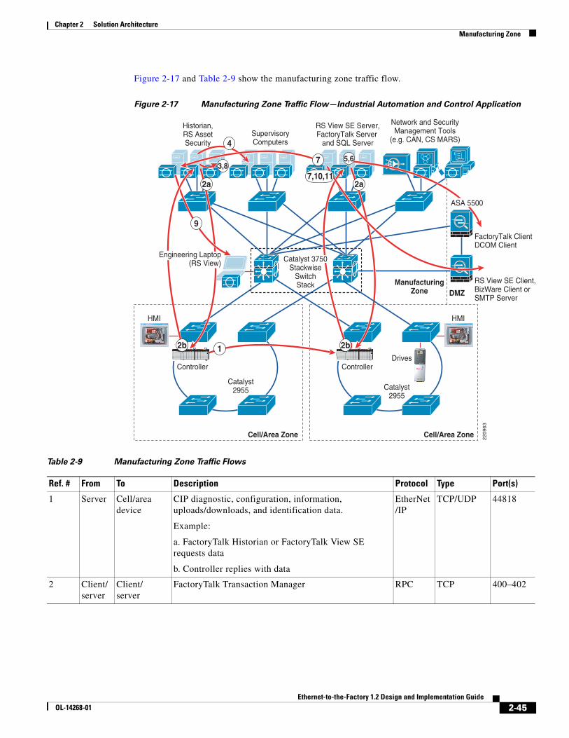
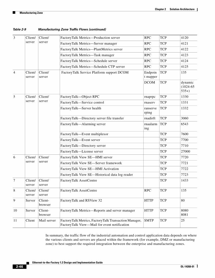
Manufacturing Zone
The manufacturing zone comprises the cell/area networks and site-level activities. It typically contains multiple cell/area zones. The manufacturing zone is important because all the systems, devices, and controllers critical to monitoring and controlling the factory floor operations are in this zone. To preserve smooth plant operations and functioning of the systems and network, this zone requires clear logical segmentation and protection from the above levels of plant/enterprise operations. Beyond the cell/area networks, there is one additional level of activity that comprises the manufacturing zone.
2-4Ethernet-to-the-Factory 1.2 Design and Implementation Guide
OL-14268-01
Chapter 2 Solution Architecture Overview
Level 3—Site Level
Level 3, the site level, represents the highest level of industrial automation and control systems. The systems and applications that exist at this level manage site-wide industrial automation and control functions. Levels 0 through 3 are considered critical to site operations. The systems and functions that exist at this level include the following:
• Production reporting (for example, cycle times, quality index, predictive maintenance)
• Plant historian
• Detailed production scheduling
• Site-level operations management
• Asset and material management
• Control room workstations
• Patch launch server
• File server
• Other domain, AD, terminal server
• Staging area
• Administration and control applications (for example, domain servers, patch distribution, terminal services)
These systems may communicate with the PACs in Level 1, function as a staging area for changes into the production zone, and share data with the enterprise (Levels 4/5) systems and applications. These systems are primarily based on standard computing equipment and operating systems (Unix-based or Microsoft Windows). For this reason, these systems are more likely to communicate with standard networking protocols (Ethernet and TCP/IP).
Additionally, because these systems tend to be more aligned with standard IT technologies, they may also be implemented and supported by IT-skilled personnel. These people may or may not belong organizationally to IT.
Enterprise Zone
Level 4—Site Business Planning and Logistics
Level 4 is where the functions and systems that need standard access to services provided by the enterprise network reside. This level is viewed as an extension of the enterprise network. The basic business administration tasks are performed here and rely on standard IT services. These functions and systems include wired and wireless access to enterprise network services such as the following:
• Internet access
• E-mail
• Non-critical production systems such as manufacturing execution systems and overall plant reporting, such as inventory, performance, etc.
• Enterprise applications such as SAP and Oracle
Although important, these services are not viewed as critical to the industrial automation and control system and thus the factory floor operations. Because of the more open nature of the systems and applications within the enterprise network, this level is often viewed as a source of threats and disruptions to the industrial automation and control network.
2-5Ethernet-to-the-Factory 1.2 Design and Implementation Guide
OL-14268-01
Chapter 2 Solution Architecture Overview
The users and systems in Level 4 often require summarized data and information from the lower levels of the industrial automation and control network. The network traffic and patterns here are typical of a branch or campus network found in general enterprises.
This level is typically under the management and control of the IT organization.
Level 5—Enterprise
Level 5 is where the centralized IT systems and functions exist. Enterprise resource management, business-to-business, and business-to-customer services typically reside at this level. Often the external partner or guest access systems exist here, although it is not uncommon to find them in lower levels of the framework to gain flexibility that may be difficult to achieve at the enterprise level.
The industrial automation and control systems must integrate with the enterprise applications to exchange production and resource data. Direct access to the industrial automation and control systems is typically not required, with the exception of partner access. Access to data and the industrial automation and control network must be managed and controlled to maintain the availability and stability.
The services, systems, and applications at this level are directly managed and operated by the IT organization.
Ethernet-to-the-Factory Framework
The Purdue Model and ISA SP99 have identified levels of operations and key zones for industrial automation and controls systems. In addition to the levels and zones, Cisco includes an additional demilitarized zone (DMZ) between the enterprise and manufacturing zones. The purpose of the DMZ is to provide a buffer zone where data and services can be shared between the enterprise and manufacturing zones. The introduction of the DMZ is critical in maintaining availability, addressing security vulnerabilities, and abiding by regulatory compliance mandates. In addition, the DMZ allows for segmentation of organizational control; for example, between the IT organization and production. This segmentation allows different policies to be applied and contained. For example, the production organization may apply security policies that are different from the IT organization, and apply them to the manufacturing zone. The DMZ is where the policies and organizational control can be divided.
These levels and zones form the base framework around which the network infrastructure and services are designed for the EttF solution (see Figure 2-2).
The following sections contain a more detailed description of each zone, including the DMZ and their related functions and components.
2-6Ethernet-to-the-Factory 1.2 Design and Implementation Guide
OL-14268-01
Chapter 2 Solution Architecture Overview
Figure 2-2 Ethernet-to-the-Factory Framework
TerminalServices
Level 5
Level 4
HistorianMirror
Web ServicesOperations
OperatorInterface
OperatorInterface
EngineeringWorkstation
ApplicationServer
PatchManagement
Enterprise Network
Site Business Planning and Logistics NetworkEmail, Intranet, etc
AVServer
Level 3
Level 2
Level 1
Level 0
Cell/AreaZone
Firewall
Firewall
Router
SupervisoryControl
SupervisoryControl
ProductionControl
BatchControl
DiscreteControl
SequenceControl
ContinuousControl
HybridControl
OptimizingControl
ProcessHistory
DomainController Site Manufacturing
Operations and Control
AreaSupervisory
Control
BasicControl
ProcessSensors Drives RobotsActuators
2209
61
2-7Ethernet-to-the-Factory 1.2 Design and Implementation Guide
OL-14268-01
Chapter 2 Solution Architecture Overview
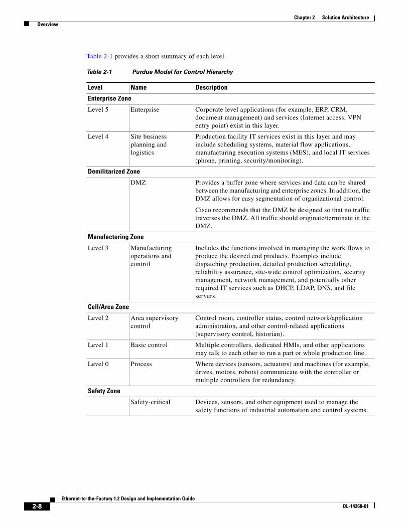
Table 2-1 provides a short summary of each level.
Table 2-1 Purdue Model for Control Hierarchy
Level Name Description
Enterprise Zone
Level 5 Enterprise Corporate level applications (for example, ERP, CRM, document management) and services (Internet access, VPN entry point) exist in this layer.
Level 4 Site business planning and logistics
Production facility IT services exist in this layer and may include scheduling systems, material flow applications, manufacturing execution systems (MES), and local IT services (phone, printing, security/monitoring).
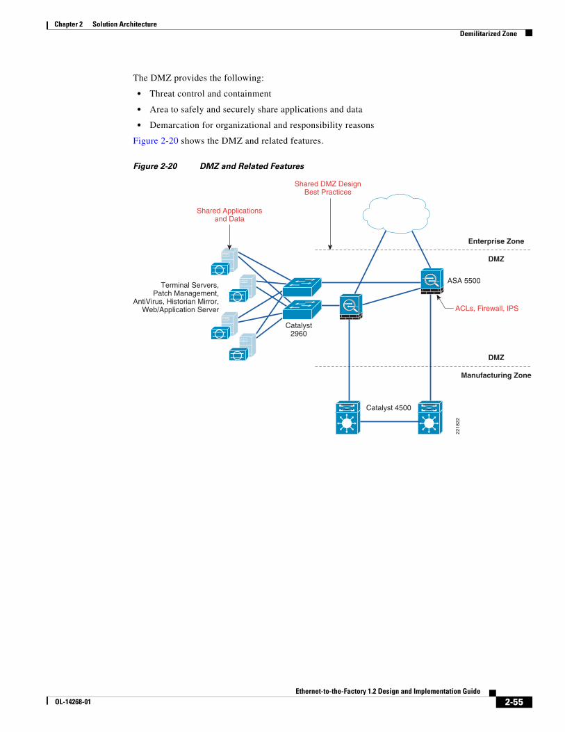
Demilitarized Zone
DMZ Provides a buffer zone where services and data can be shared between the manufacturing and enterprise zones. In addition, the DMZ allows for easy segmentation of organizational control.
Cisco recommends that the DMZ be designed so that no traffic traverses the DMZ. All traffic should originate/terminate in the DMZ.
Manufacturing Zone
Level 3 Manufacturing operations and control
Includes the functions involved in managing the work flows to produce the desired end products. Examples include dispatching production, detailed production scheduling, reliability assurance, site-wide control optimization, security management, network management, and potentially other required IT services such as DHCP, LDAP, DNS, and file servers.
Cell/Area Zone
Level 2 Area supervisory control
Control room, controller status, control network/application administration, and other control-related applications (supervisory control, historian).
Level 1 Basic control Multiple controllers, dedicated HMIs, and other applications may talk to each other to run a part or whole production line.
Level 0 Process Where devices (sensors, actuators) and machines (for example, drives, motors, robots) communicate with the controller or multiple controllers for redundancy.
Safety Zone
Safety-critical Devices, sensors, and other equipment used to manage the safety functions of industrial automation and control systems.
2-8Ethernet-to-the-Factory 1.2 Design and Implementation Guide
OL-14268-01
Chapter 2 Solution Architecture Overview
Campus Network Reference ModelThe EttF framework reflects the basic functions of a production facility. This is the key model for this solution architecture. However, as identified earlier, the goal of this architecture is to integrate the knowledge and expertise from both a manufacturing perspective as well as an IT perspective where expertise in standard networking technologies exists. An important and relevant model for network architectures is the Cisco Enterprise Campus Network. The enterprise campus solution architecture incorporates key networking concepts and models. The EttF solution architecture comprises many of the concepts and models of the enterprise campus solution architecture, although it does not incorporate the entire scope of that solution because not all concepts are applicable to the production facility.
This section briefly introduces the campus network and some of the key concepts of its solution architecture. The Cisco Enterprise Campus Network combines a high-availability core infrastructure of intelligent switching and routing with an overlay of productivity-enhancing technologies, including IP communications, mobility, and advanced security. This document refers to the campus network documentation and the concept of core, distribution, and access. Not all aspects of a campus network design are reflected in this solution architecture, such as wireless mobility and unified communications.
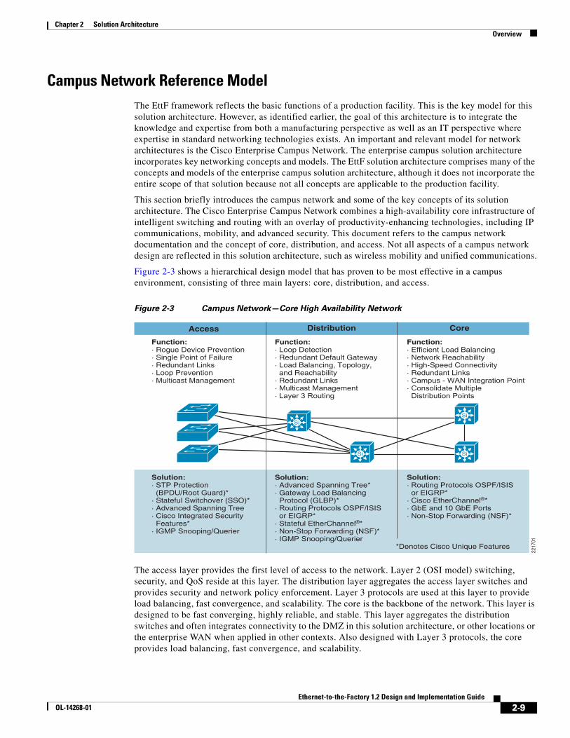
Figure 2-3 shows a hierarchical design model that has proven to be most effective in a campus environment, consisting of three main layers: core, distribution, and access.
Figure 2-3 Campus Network—Core High Availability Network
The access layer provides the first level of access to the network. Layer 2 (OSI model) switching, security, and QoS reside at this layer. The distribution layer aggregates the access layer switches and provides security and network policy enforcement. Layer 3 protocols are used at this layer to provide load balancing, fast convergence, and scalability. The core is the backbone of the network. This layer is designed to be fast converging, highly reliable, and stable. This layer aggregates the distribution switches and often integrates connectivity to the DMZ in this solution architecture, or other locations or the enterprise WAN when applied in other contexts. Also designed with Layer 3 protocols, the core provides load balancing, fast convergence, and scalability.
Access
Function:· Rogue Device Prevention· Single Point of Failure· Redundant Links· Loop Prevention· Multicast Management
Function:· Efficient Load Balancing· Network Reachability· High-Speed Connectivity· Redundant Links· Campus - WAN Integration Point· Consolidate Multiple Distribution Points
Solution:· Routing Protocols OSPF/ISIS or EIGRP*· Cisco EtherChannel®*· GbE and 10 GbE Ports· Non-Stop Forwarding (NSF)*
Distribution Core
*Denotes Cisco Unique Features
2217
01
Si
Si Si
Si
2-9Ethernet-to-the-Factory 1.2 Design and Implementation Guide
OL-14268-01
Chapter 2 Solution Architecture Cell/Area Zone
This three-layer design provides high availability with redundant hardware, redundant software features, redundant network connections/paths, and automatic procedures for reconfiguring network paths when failures occur. The highly available campus network architecture emphasizes no single points of failure on critical links and automatic recovery of failures.
The access layer provides the first level of access to the network and focuses on security and Quality of Service (QoS) features that can be propagated to the higher layers. The distribution layer aggregates the access layer switches and provides security and network policy enforcement. This layer also provides Layer 3 routing, for example between VLANs, fast convergence features such as Hot Standby Router Protocol (HSRP) and Gateway Load Balancing Protocol (GLBP) and scalability. The core is the backbone of the network and provides high-speed transport between distribution-layer devices and core resources This layer often integrates connectivity to the DMZ in this solution architecture, or other locations or the enterprise WAN when applied in other contexts. Also designed with Layer 3 protocols, the core provides load balancing, fast convergence, and scalability.
In addition to the high availability switching and routing network, the enterprise campus architecture incorporates the following three core networking functions:
• Network security based on the Cisco Self-Defending Network
• IP-based communications
• Mobility and wireless LAN services
For more information on the enterprise campus network, refer to the following URL: http://www.cisco.com/en/US/netsol/ns340/ns394/ns431/networking_solutions_packages_list.html
Cell/Area Zone
OverviewThe cell/area network is the major building block of the EttF architecture. This is the network that connects devices, controllers, and any other devices that need to communicate in real-time (I/O communication) with these devices. This section outlines the key technical considerations that need to be addressed in the test environment and design guidelines. In addition to the specific technical considerations for a cell/area network, the design guidelines also provide guidance on the design of a cell/area zone. The approach generally recommended is to design the cell/area by functional role of the devices and systems, rather than a design by device type, which is a common consideration. The design guidelines must indicate how customers can arrive at a cell/area network design schema that meets the performance requirements of the industrial automation and control systems.
An important distinction in this solution architecture is that the cell/area zone is considered a Layer 2 or LAN network. Layer 3 or IP routing features and functions are considered as part of the manufacturing zone (also including Level 3). Even so, a Layer 3 switch or router is an important component of the cell/area zone because it performs critical Layer 2 network roles, such as Spanning Tree Protocol (STP) root bridge and Internet Group Management Protocol (IGMP) querier.
A cell/area zone network is very different from a typical IT access layer network (the term that IT may use for this network). The difference is related to the following:
• Environment in which it operates—Production facilities operate in conditions required by the manufacturing process taking place. This process can lead to extended temperature, humidity, invasive materials, shock, vibration, and multiple types of noise. The equipment operating in these environments must be designed and tested for these conditions.
2-10Ethernet-to-the-Factory 1.2 Design and Implementation Guide
• Industrial automation and control devices and applications—Relatively “dumb” to sophisticated Level 1 devices talking to a Level 2 controllers and Level 3 workstations and HMIs.
• Industrial automation and control systems also are very demanding of the cell/area network. Level 0 devices can be very simple devices with limited software and processing capabilities, which makes them susceptible to network-related disruptions or extraneous communication. In addition, a very quickly changing manufacturing process (for example, a paper mill), or complex automation (for example, multi-axis robot) demand very high levels of determinism in the industrial automation and control system. These then require real-time communication from the network infrastructure.
The combination of the demanding environmental conditions of the manufacturing process and the industrial automation and control systems drive particular requirements of the cell/area network design. In summary, key design considerations are as follows:
• Environment—The conditions of the factory floor must be taken into consideration, because the equipment must be able to perform in these conditions. The network topology must be shaped to fit appropriately into the factory floor environment.
• Real-time communications and network performance—A cell/area network must be designed to meet the latency and jitter requirements of the industrial automation and control system it supports. This can impact the size of the LAN, the number of hops, the VLAN configuration, and a number of other network parameters.
• Availability—The availability of the cell/area network is directly attributable to the uptime of the manufacturing process it supports. The network must also be able to recover from network impacting events (for example, connection break) faster than the cycle time of the industrial automation control system to avoid the system automatically shutting down. Availability impacts the network design, topology, and even the type of equipment used.
• Manageability—The factory floor is usually not supported in the same manner as an IT network. First, the factory floor maintenance personnel tend not to have the networking expertise to perform anything beyond the most basic tasks. The setup and maintenance of network equipment and configuration must be simplified to meet the expertise level of the production floor maintenance personnel.
• Security—The factory floor tends to be protected physically from attack or exposure, but is the most sensitive area in that the devices are highly susceptible to network-borne attacks (for example, denial of service). Other sections of this architecture provide various forms of insulation for the cell/area zone, but certain precautions in the cell/area zone as well can significantly improve security.
• Unmanaged versus managed—The network infrastructure may not represent a large proportion of the factory floor (implementation or maintenance), but the same cost reduction mentality is applied as to other aspects of the production facility. In fact, because of a lack of understanding of the qualities of a managed, intelligent network, the additional costs they represent may lead customers to choose less intelligent solutions based purely on cost considerations; only later do they determine that the cheaper, unmanaged infrastructure cannot scale, perform, integrate, or be as easily maintained as an intelligent, managed network.
All these factors directly impact the components, topology, traffic flow, and network design, each of which is explored in the following sections.
2-11Ethernet-to-the-Factory 1.2 Design and Implementation Guide
OL-14268-01
Chapter 2 Solution Architecture Cell/Area Zone
ComponentsA cell/area zone comprises the following (see Figure 2-4):
• EttF Levels 0, 1, and 2 components; for example, devices, controllers, and HMIs
• Layer 2 access switches
• Layer 3 distribution switches or routers
• Media to connect all of the above
Figure 2-4 Cell/Area Components
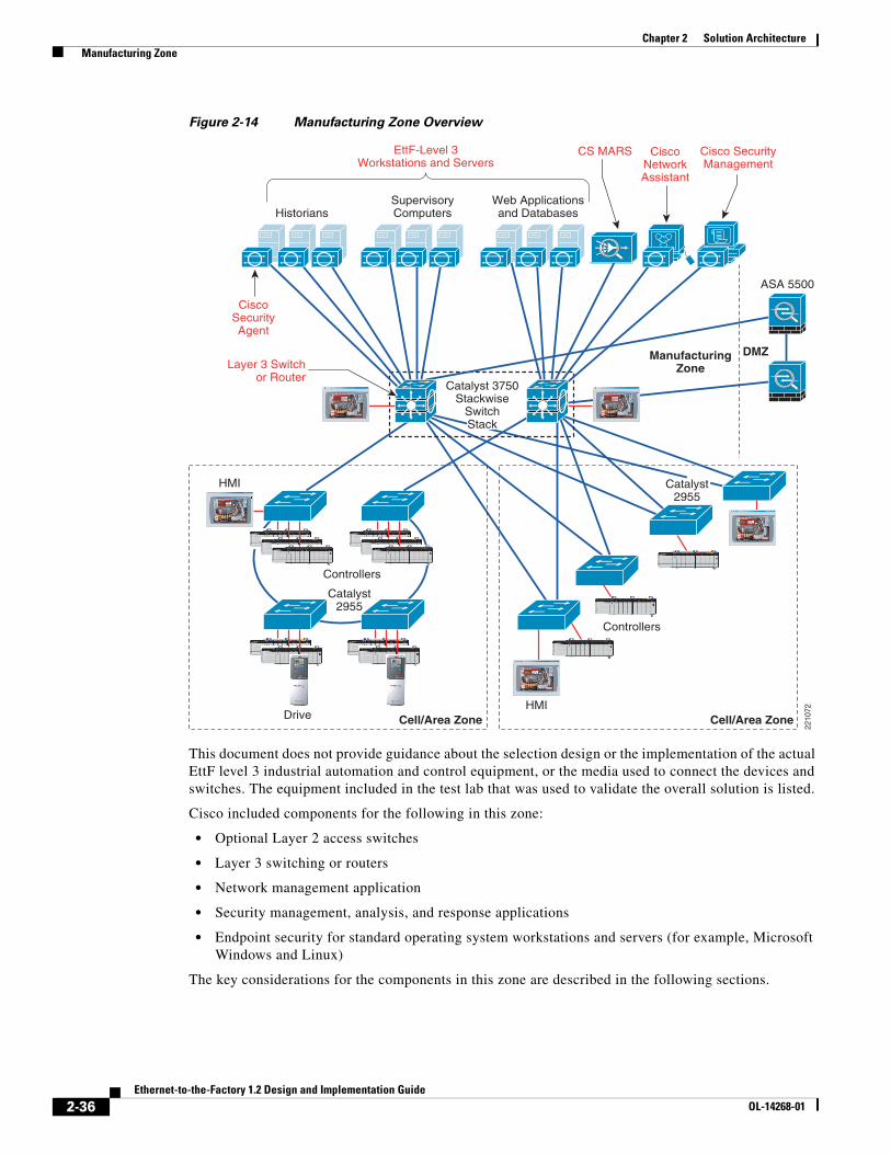
This document does not provide guidance about the selection or implementation of the actual industrial automation and control equipment or the media used to connect the devices and switches. The equipment included in the test lab used to validate the overall solution is listed.
The key considerations customers go through when selecting the network infrastructure include the following:
• Cost—Managed switches are typically more expensive than hubs or unmanaged switches.
• Environment—Does the switch meet the environmental conditions in which the equipment must operate?
• Availability—How critical is the process being supported by the cell/area network to overall production? What level of operation is the cell/area network expected to operate? What is the cost of downtime?
• Flexibility—What variations of power, number of ports, type of media connections, mounting, and so on, does the switch support to meet the variety of situations in the production environment?
• Manageability—Can the device be easily maintained? What support and warranty options are available? Often, industrial automation and control systems can be operational for more than five years, even into decades.
Catalyst 3750Stackwise
SwitchStack
HMI
HMI
Drives
EttF-Level 2 HMI
Media andConnectors
EttF-Level 1Controller
EttF-Level 0Device (Drive)
2210
12
Catalyst2955
Catalyst2955
Layer 2Access Switch
Cell/Area Zone Cell/Area Zone
Layer 3Distribution
Switch
Controllers Controllers
2-12Ethernet-to-the-Factory 1.2 Design and Implementation Guide
OL-14268-01
Chapter 2 Solution Architecture Cell/Area Zone
• Security—What security capabilities does the switch provide?
• Support—What type of support is available? What are the warranty options available?
Unmanaged versus Managed Switches
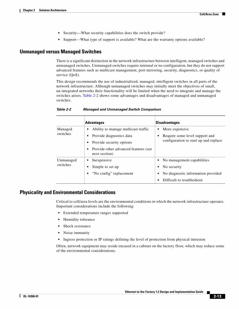
There is a significant distinction in the network infrastructure between intelligent, managed switches and unmanaged switches. Unmanaged switches require minimal or no configuration, but they do not support advanced features such as multicast management, port mirroring, security, diagnostics, or quality of service (QoS).
This design recommends the use of industrialized, managed, intelligent switches in all parts of the network infrastructure. Although unmanaged switches may initially meet the objectives of small, un-integrated networks their functionality will be limited when the need to integrate and manage the switches arises. Table 2-2 shows some advantages and disadvantages of managed and unmanaged switches.
Physicality and Environmental Considerations
Critical to cell/area levels are the environmental conditions in which the network infrastructure operates. Important considerations include the following:
• Extended temperature ranges supported
• Humidity tolerance
• Shock resistance
• Noise immunity
• Ingress protection or IP ratings defining the level of protection from physical intrusion
Often, network equipment may reside encased in a cabinet on the factory floor, which may reduce some of the environmental considerations.
Table 2-2 Managed and Unmanaged Switch Comparison
Advantages Disadvantages
Managed switches
• Ability to manage multicast traffic
• Provide diagnostics data
• Provide security options
• Provide other advanced features (see next section)
• More expensive
• Require some level support and configuration to start up and replace
Unmanaged switches
• Inexpensive
• Simple to set up
• “No config” replacement
• No management capabilities
• No security
• No diagnostic information provided
• Difficult to troubleshoot
2-13Ethernet-to-the-Factory 1.2 Design and Implementation Guide
OL-14268-01
Chapter 2 Solution Architecture Cell/Area Zone
Real-Time Communications
A switch plays a key role in real-time communications. Key considerations for a switch performance include the following:
• Bandwidth supported on both access ports (typically 100 Mbps) and uplink ports (typically 1 Gbps).
• Virtual LAN (VLAN) support. VLANs allow several devices to be logically grouped, regardless of their physical location into a single broadcast domain. Using VLANS to segment traffic flows is key to achieving overall system performance.
• QoS support at both the Ethernet/CoS and IP/ToS layers.
• Multicast management features (for example, IGMP snooping). For more information about IGMP, see Multicast Design, page 4-15.
Availability
The switch impacts overall availability of the industrial automation and control system because the switch is often a single point of failure if devices are connected only to a single switch. Thus, availability considerations are important and include the following:
• Passive cooling or no moving parts (for example, fans).
• Mean time to break/fix ratings.
• Storm control and rate limiting to protect the network and other devices from out-of-control network communications.
• Support for convergence protocols, such as STP and Rapid STP (RSTP). For more information about Spanning Tree, see Spanning Tree Protocol Design, page 4-7.
Flexibility
The flexibility of the industrial Ethernet network is also a consideration. To efficiently support an industrial automation and control system, the network infrastructure should come in variations that include the following:
• Multiple port configurations
• Connections supported, such as fiber, small form-factor pluggables (SFPs), and copper/RJ45
• Power support—AC/DC in wide varieties as well as potential for redundant power
• Mounting support
2-14Ethernet-to-the-Factory 1.2 Design and Implementation Guide
OL-14268-01
Chapter 2 Solution Architecture Cell/Area Zone
Manageability
The manageability of the network infrastructure is also important. The switch is typically maintained by factory floor operations personnel who may have minimal network expertise. Basic management functions such as initial configuration, break/fix, and monitoring need to be relatively easy. Key considerations include the following:
• SNMP capable—Most network device vendors support management via the Simple Network Management protocol (SNMP) v3.
• Smartport configurations—Smartports allow pre-defined port configurations to be used that ease configuration of a switch.
• Ease of installation, setup, and maintenance. The network infrastructure should be easy to install, set up, and maintain with key basic functions available to plant floor personnel and applications. Optimally, the network devices should interface with the automation and control applications to present a common interface for plant floor personnel.
• Warranty and support.
• CIP support—The ability for the switch to interface with the industrial automation and control systems for some basic functions greatly eases ongoing maintenance.
Security
The Layer 2 access switch can play an important role in security as a port of entry to the manufacturing and cell/area zones. Some key considerations include the following:
• Access control lists (ACLs) to configure security policies into a switch.
• Virtual LAN support as a basic building block of a security approach. For more information about VLANs , see Virtual LAN Segmentation, page 4-3.
• Secure Shell (SSH) switch OS access.
• SNMPv3 support for encryption of this important protocol for managing and monitoring the network infrastructure.
• MAC address notification.
• Port Security via MAC address identification.
2-15Ethernet-to-the-Factory 1.2 Design and Implementation Guide
OL-14268-01
Chapter 2 Solution Architecture Cell/Area Zone
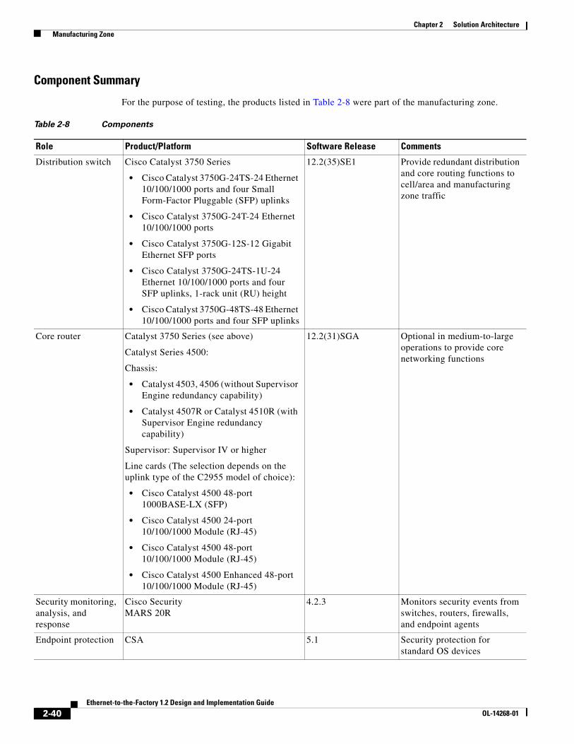
Component Summary
Table 2-3 lists the EttF testing lab component selections for the cell/area networks.
Table 2-3 Cell/Area Network Components
Role Product/Platform Software Release Comments
Layer 2 access switch
Cisco Catalyst 2955 T-12, 12 10/100 ports, and two fixed 10/100/1000BASE-T uplink ports
Catalyst 2960 for non-industrial environments
12.1(22)EA6 Connects EttF-Level 0-2 devices to the network
The only industrial Ethernet switch Cisco currently offers
For more details, see http://www.cisco.com/go/2955
Layer 3 distribution switch
• Cisco Catalyst 3750G-24TS-24 Ethernet 10/100/1000 ports and four Small Form-Factor Pluggable (SFP) uplinks
• Cisco Catalyst 3750G-24TS-1U-24 Ethernet 10/100/1000 ports and four SFP uplinks, 1-rack unit (RU) height
• Cisco Catalyst 3750G-48TS-48 Ethernet 10/100/1000 ports and four SFP uplinks
12.2(35)SE1 Provides inter-connection to cell/area zones. In cell/area VLANs, performs some LAN roles; for example, in STP root bridge and IGMP querier.
The price/performance and port density of this switch has already made it a dominant choice for this role in existing EttF implementations.
2-16Ethernet-to-the-Factory 1.2 Design and Implementation Guide
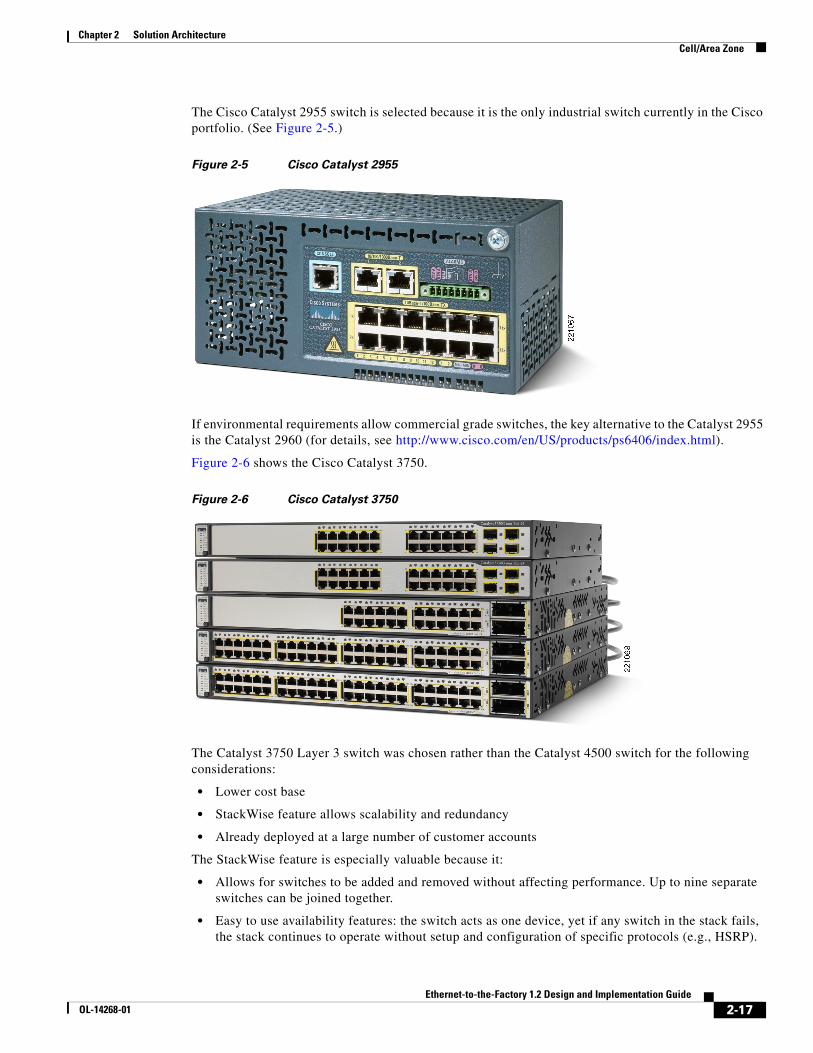
The Cisco Catalyst 2955 switch is selected because it is the only industrial switch currently in the Cisco portfolio. (See Figure 2-5.)
Figure 2-5 Cisco Catalyst 2955
If environmental requirements allow commercial grade switches, the key alternative to the Catalyst 2955 is the Catalyst 2960 (for details, see http://www.cisco.com/en/US/products/ps6406/index.html).
Figure 2-6 shows the Cisco Catalyst 3750.
Figure 2-6 Cisco Catalyst 3750
The Catalyst 3750 Layer 3 switch was chosen rather than the Catalyst 4500 switch for the following considerations:
• Lower cost base
• StackWise feature allows scalability and redundancy
• Already deployed at a large number of customer accounts
The StackWise feature is especially valuable because it:
• Allows for switches to be added and removed without affecting performance. Up to nine separate switches can be joined together.
• Easy to use availability features: the switch acts as one device, yet if any switch in the stack fails, the stack continues to operate without setup and configuration of specific protocols (e.g., HSRP).
2-17Ethernet-to-the-Factory 1.2 Design and Implementation Guide
A chassis-based switch such as the Catalyst 4500 or Catalyst 6500 may be ideal in the following situations:
• Capacity or scalability is a concern; for example, when integrating a large number of cell/area networks
• Upgradeable processor and interfaces for longer-term viability
• Better failover features for availability; for example, in-service upgradeability
• When service modules (such as firewall and application delivery) are required.
The components in consideration for this phase of the solution architecture are connected via single connections to the network infrastructure. This is common for the industrial automation and control systems applying the CIP protocol. Although controllers may and often do have more than one Ethernet connection, they are typically not working in a high-availability configuration where one card assumes the IP address of the other in the event of failure. Dual-connected for high availability cell/area devices are not considered in this solution architecture at this time.
Traffic FlowsTraffic flow in a cell/area network is largely determined by the design and implementation of the industrial automation and control systems. These systems produce very different traffic patterns than the client-server and Internet-based applications in the IT domain. For example, 80–90 percent of the cell/area traffic is local as compared to a typical IT LAN in which perhaps less than 10 percent of the traffic is local. This is primarily driven by the cyclical I/O data being communicated on very short intervals (milliseconds) from devices to controllers and workstations/HMIs all on the same LAN or VLAN.
A network infrastructure should be designed to support the proper traffic flows. Features such as network segmentation can impact the network traffic flows and network performance.
Key considerations when designing traffic flows include the following:
• Current EtherNet/IP implementations have traditionally been unable to route multicast traffic since the time-to-live field in the IP packet is set to 1. Although the recently released CIP EtherNet/IP specifications (CIP Specifications version 1.3, Volume 2 EtherNet/IP Adaptation of CIP, December 2006) call for this limit to be removed, these design and implementation guides are based on the limitation because the routing of multicast traffic requires a more complex set of protocols and considerations to be applied.
• The use of multicast for implicit traffic is a vendor choice, and is the prevalent choice. The most recent version of the Rockwell Controller program application (RSLogix) allows customers to choose unicast rather than multicast delivery for certain types of data. These design and implementation guidelines are based on the mode where all producer-generated I/O is multicast. Devices and controllers that communicate with each other need to be in the same cell/area.
Note However, Cisco recommends that customers consider and apply this unicast/multicast option to maintain the size of the cell/area networks. This suggests choosing to use unicast delivery for PAC-to-PAC data/tags shared between two PACs where using multicast forces the cell/area network to be larger.
• A baseline of the amount of CIP/IO traffic on the network should be collected. Based on that discovery, the proper network bandwidth should be provisioned to the cell/area in order to avoid oversubscribing connections and to meet the real-time communication requirements.
2-18Ethernet-to-the-Factory 1.2 Design and Implementation Guide
OL-14268-01
Chapter 2 Solution Architecture Cell/Area Zone
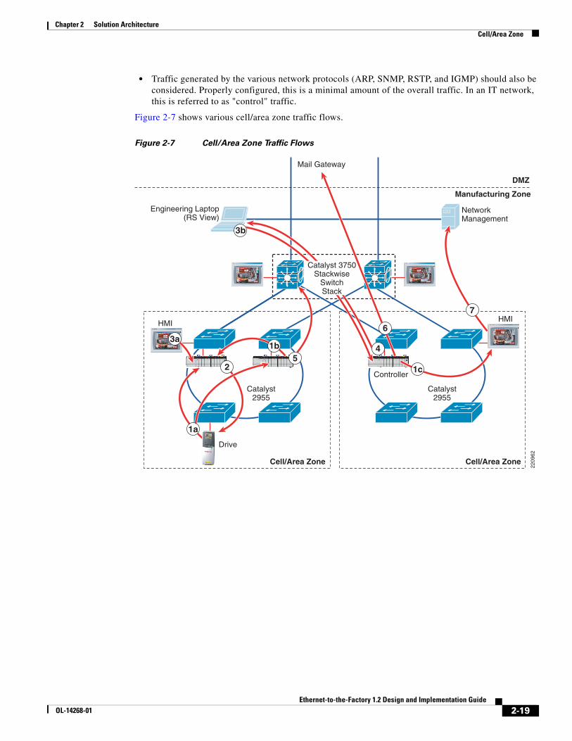
• Traffic generated by the various network protocols (ARP, SNMP, RSTP, and IGMP) should also be considered. Properly configured, this is a minimal amount of the overall traffic. In an IT network, this is referred to as "control" traffic.
Figure 2-7 shows various cell/area zone traffic flows.
Figure 2-7 Cell/Area Zone Traffic Flows
HMI
Cell/Area Zone Cell/Area Zone
HMI
Drive
Controller
Mail Gateway
Engineering Laptop(RS View)
Catalyst2955
NetworkManagement
Manufacturing Zone
DMZ
2209
62
Catalyst2955
1b
1c25
3a4
6
7
1a
3b
Catalyst 3750Stackwise
SwitchStack
2-19Ethernet-to-the-Factory 1.2 Design and Implementation Guide
OL-14268-01
Chapter 2 Solution Architecture Cell/Area Zone
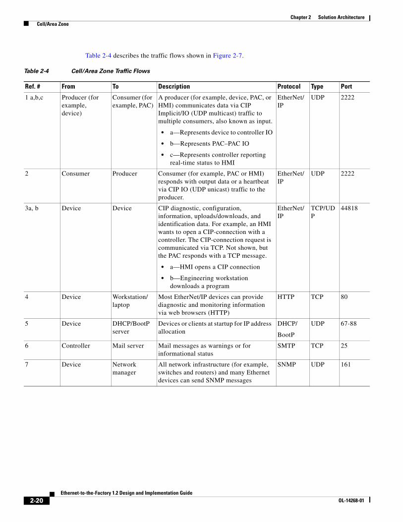
Table 2-4 describes the traffic flows shown in Figure 2-7.
Table 2-4 Cell/Area Zone Traffic Flows
Ref. # From To Description Protocol Type Port
1 a,b,c Producer (for example, device)
Consumer (for example, PAC)
A producer (for example, device, PAC, or HMI) communicates data via CIP Implicit/IO (UDP multicast) traffic to multiple consumers, also known as input.
• a—Represents device to controller IO
• b—Represents PAC–PAC IO
• c—Represents controller reporting real-time status to HMI
EtherNet/IP
UDP 2222
2 Consumer Producer Consumer (for example, PAC or HMI) responds with output data or a heartbeat via CIP IO (UDP unicast) traffic to the producer.
EtherNet/IP
UDP 2222
3a, b Device Device CIP diagnostic, configuration, information, uploads/downloads, and identification data. For example, an HMI wants to open a CIP-connection with a controller. The CIP-connection request is communicated via TCP. Not shown, but the PAC responds with a TCP message.
• a—HMI opens a CIP connection
• b—Engineering workstation downloads a program
EtherNet/IP
TCP/UDP
44818
4 Device Workstation/laptop
Most EtherNet/IP devices can provide diagnostic and monitoring information via web browsers (HTTP)
HTTP TCP 80
5 Device DHCP/BootP server
Devices or clients at startup for IP address allocation
DHCP/
BootP
UDP 67-88
6 Controller Mail server Mail messages as warnings or for informational status
SMTP TCP 25
7 Device Network manager
All network infrastructure (for example, switches and routers) and many Ethernet devices can send SNMP messages
SNMP UDP 161
2-20Ethernet-to-the-Factory 1.2 Design and Implementation Guide
OL-14268-01
Chapter 2 Solution Architecture Cell/Area Zone
Topology Options OverviewThe cell/area network is where the various physical topologies are required to meet physical constraints of the factory floor. The network infrastructure (cabling, switches, and so on) must fit into the layout of the manufacturing process. A large variety of network topologies must be considered. This document considers the redundant star, ring, and trunk-drop.
Note This document provides no specific design and implementation guidance for other topologies that may be supported as well, such as tree and hub-and-spoke.
Topology starts with considering how devices are connected to the network. In many industrial automation and control systems, the devices themselves support only single network connections, and therefore are connected via only a single connection to a single access switch. Where availability is critical and the devices support multiple connections, they should be connected to multiple switches to avoid single points of failure. In those cases, the network infrastructure should be configured in such a way to support the resiliency/redundancy of the overall manufacturing process.
Key considerations include the following:
• Physical layout—The layout of the manufacturing environment is a key driver of topology design. For example, a long conveyor belt system does not easily lend itself to a redundant star configuration, but rather a trunk-drop or ring.
• Availability—Cisco recommends using resilient network topologies (for example, redundant star and ring) over non-redundant topologies. These allow the network to continue to function after an event such as connection loss or switch failure. Although some of these events may still lead to downtime of the industrial automation and control systems, a resilient network topology may reduce that chance and should improve the recovery time.
• Real-time communications—Latency and jitter are impacted by a large variety of factors, but primary by the amount of traffic and number of hops a packet must make to reach its destination. The amount of traffic in a Layer 2 network is driven by various factors, but the number of nodes is important. Key guidelines include the following:
– Amount of latency introduced per Layer 2 hop.
– Bandwidth should not consistently exceed 50 percent of the interface capacity on any switch.
– CPU should not consistently exceed 50–70 percent utilization. Above this level, the chances increase significantly that the switch may not properly process control packets and start behaving abnormally.
The key connectivity considerations made for the test environment include the following:
• Devices are connected to a switch via a single network connection or an IP-enabled I/O block or linking device if they do not support Ethernet natively. Note that most devices (including PACs) have limited or no failover capabilities and therefore cannot effectively use redundant network connections.
• Redundant network connections were not considered for this phase. Redundant connections may be used in certain industries and applications; mostly process-related industries applied to critical infrastructure.
• Switches may be arranged in a star, redundant star, trunk-drop, or ring network
Part of the validation phase is to generate guidelines for the size of a cell/area network and the limits of determinism that can be achieved as the cell/area network increases. The cell/area network in the test environment contains up to 15 switches, in the configurations shown in the following sections.
2-21Ethernet-to-the-Factory 1.2 Design and Implementation Guide
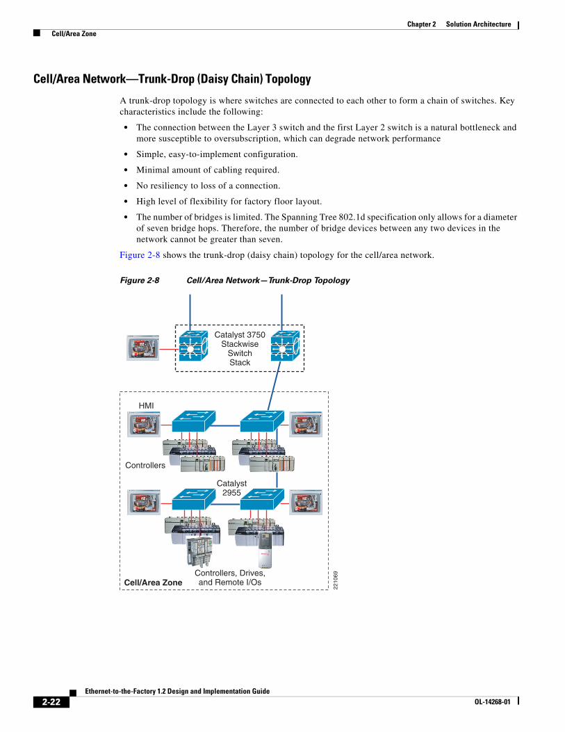
A trunk-drop topology is where switches are connected to each other to form a chain of switches. Key characteristics include the following:
• The connection between the Layer 3 switch and the first Layer 2 switch is a natural bottleneck and more susceptible to oversubscription, which can degrade network performance
• Simple, easy-to-implement configuration.
• Minimal amount of cabling required.
• No resiliency to loss of a connection.
• High level of flexibility for factory floor layout.
• The number of bridges is limited. The Spanning Tree 802.1d specification only allows for a diameter of seven bridge hops. Therefore, the number of bridge devices between any two devices in the network cannot be greater than seven.
Figure 2-8 shows the trunk-drop (daisy chain) topology for the cell/area network.
Figure 2-8 Cell/Area Network—Trunk-Drop Topology
2210
69
HMI
Catalyst2955
Controllers
Cell/Area Zone
Catalyst 3750Stackwise
SwitchStack
Controllers, Drives,and Remote I/Os
2-22Ethernet-to-the-Factory 1.2 Design and Implementation Guide
OL-14268-01
Chapter 2 Solution Architecture Cell/Area Zone
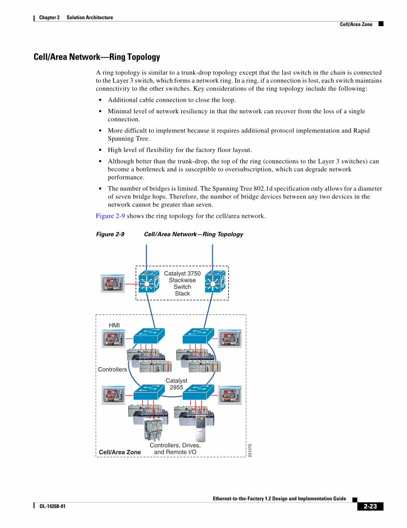
Cell/Area Network—Ring Topology
A ring topology is similar to a trunk-drop topology except that the last switch in the chain is connected to the Layer 3 switch, which forms a network ring. In a ring, if a connection is lost, each switch maintains connectivity to the other switches. Key considerations of the ring topology include the following:
• Additional cable connection to close the loop.
• Minimal level of network resiliency in that the network can recover from the loss of a single connection.
• More difficult to implement because it requires additional protocol implementation and Rapid Spanning Tree.
• High level of flexibility for the factory floor layout.
• Although better than the trunk-drop, the top of the ring (connections to the Layer 3 switches) can become a bottleneck and is susceptible to oversubscription, which can degrade network performance.
• The number of bridges is limited. The Spanning Tree 802.1d specification only allows for a diameter of seven bridge hops. Therefore, the number of bridge devices between any two devices in the network cannot be greater than seven.
Figure 2-9 shows the ring topology for the cell/area network.
Figure 2-9 Cell/Area Network—Ring Topology
2210
70
HMI
Catalyst2955
Cell/Area Zone
Catalyst 3750Stackwise
SwitchStack
Controllers
Controllers, Drives,and Remote I/O
2-23Ethernet-to-the-Factory 1.2 Design and Implementation Guide
OL-14268-01
Chapter 2 Solution Architecture Cell/Area Zone
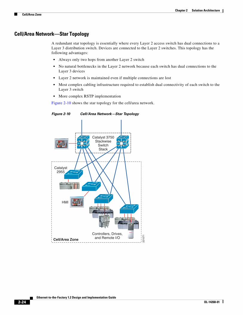
Cell/Area Network—Star Topology
A redundant star topology is essentially where every Layer 2 access switch has dual connections to a Layer 3 distribution switch. Devices are connected to the Layer 2 switches. This topology has the following advantages:
• Always only two hops from another Layer 2 switch
• No natural bottlenecks in the Layer 2 network because each switch has dual connections to the Layer 3 devices
• Layer 2 network is maintained even if multiple connections are lost
• Most complex cabling infrastructure required to establish dual connectivity of each switch to the Layer 3 switch
• More complex RSTP implementation
Figure 2-10 shows the star topology for the cell/area network.
Figure 2-10 Cell/Area Network—Star Topology
2210
71
HMI
Catalyst2955
Cell/Area Zone
Catalyst 3750Stackwise
SwitchStack
Controllers, Drives,and Remote I/O
2-24Ethernet-to-the-Factory 1.2 Design and Implementation Guide
OL-14268-01
Chapter 2 Solution Architecture Cell/Area Zone
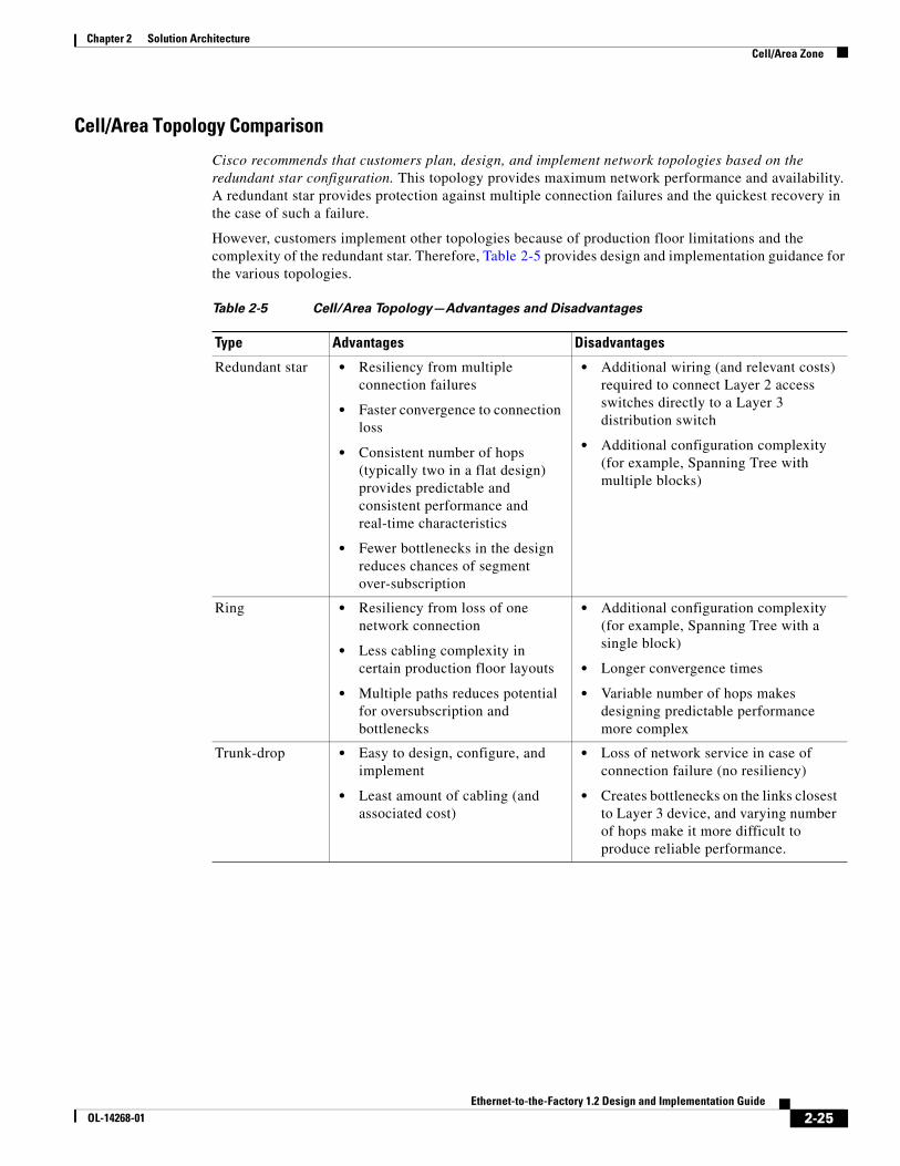
Cell/Area Topology Comparison
Cisco recommends that customers plan, design, and implement network topologies based on the redundant star configuration. This topology provides maximum network performance and availability. A redundant star provides protection against multiple connection failures and the quickest recovery in the case of such a failure.
However, customers implement other topologies because of production floor limitations and the complexity of the redundant star. Therefore, Table 2-5 provides design and implementation guidance for the various topologies.
Table 2-5 Cell/Area Topology—Advantages and Disadvantages
Type Advantages Disadvantages
Redundant star • Resiliency from multiple connection failures
• Faster convergence to connection loss
• Consistent number of hops (typically two in a flat design) provides predictable and consistent performance and real-time characteristics
• Fewer bottlenecks in the design reduces chances of segment over-subscription
• Additional wiring (and relevant costs) required to connect Layer 2 access switches directly to a Layer 3 distribution switch
• Additional configuration complexity (for example, Spanning Tree with multiple blocks)
Ring • Resiliency from loss of one network connection
• Less cabling complexity in certain production floor layouts
• Multiple paths reduces potential for oversubscription and bottlenecks
• Additional configuration complexity (for example, Spanning Tree with a single block)
• Longer convergence times
• Variable number of hops makes designing predictable performance more complex
Trunk-drop • Easy to design, configure, and implement
• Least amount of cabling (and associated cost)
• Loss of network service in case of connection failure (no resiliency)
• Creates bottlenecks on the links closest to Layer 3 device, and varying number of hops make it more difficult to produce reliable performance.
2-25Ethernet-to-the-Factory 1.2 Design and Implementation Guide
OL-14268-01
Chapter 2 Solution Architecture Cell/Area Zone
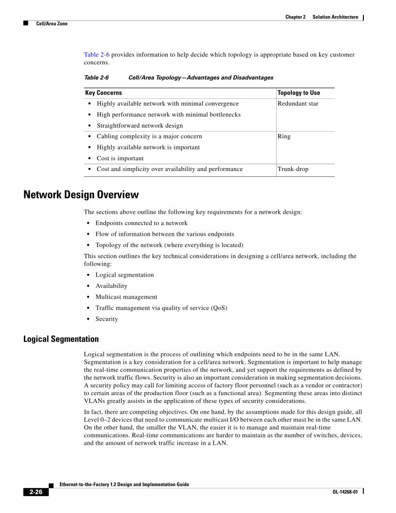
Table 2-6 provides information to help decide which topology is appropriate based on key customer concerns.
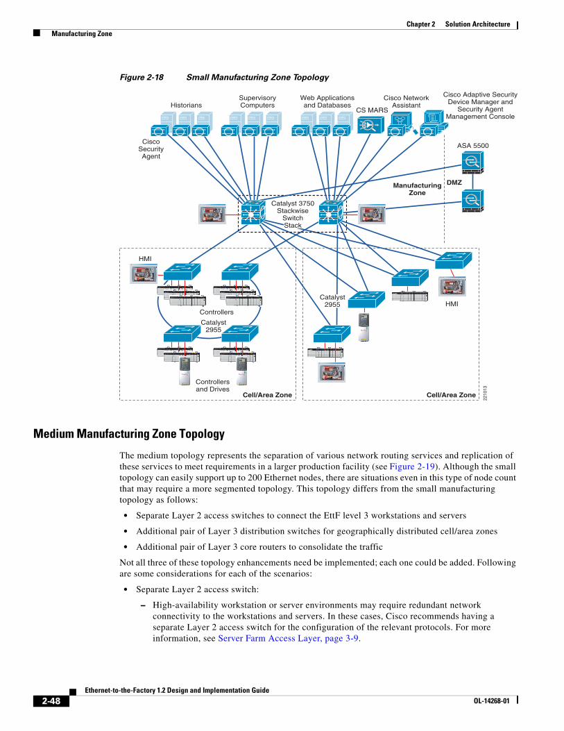
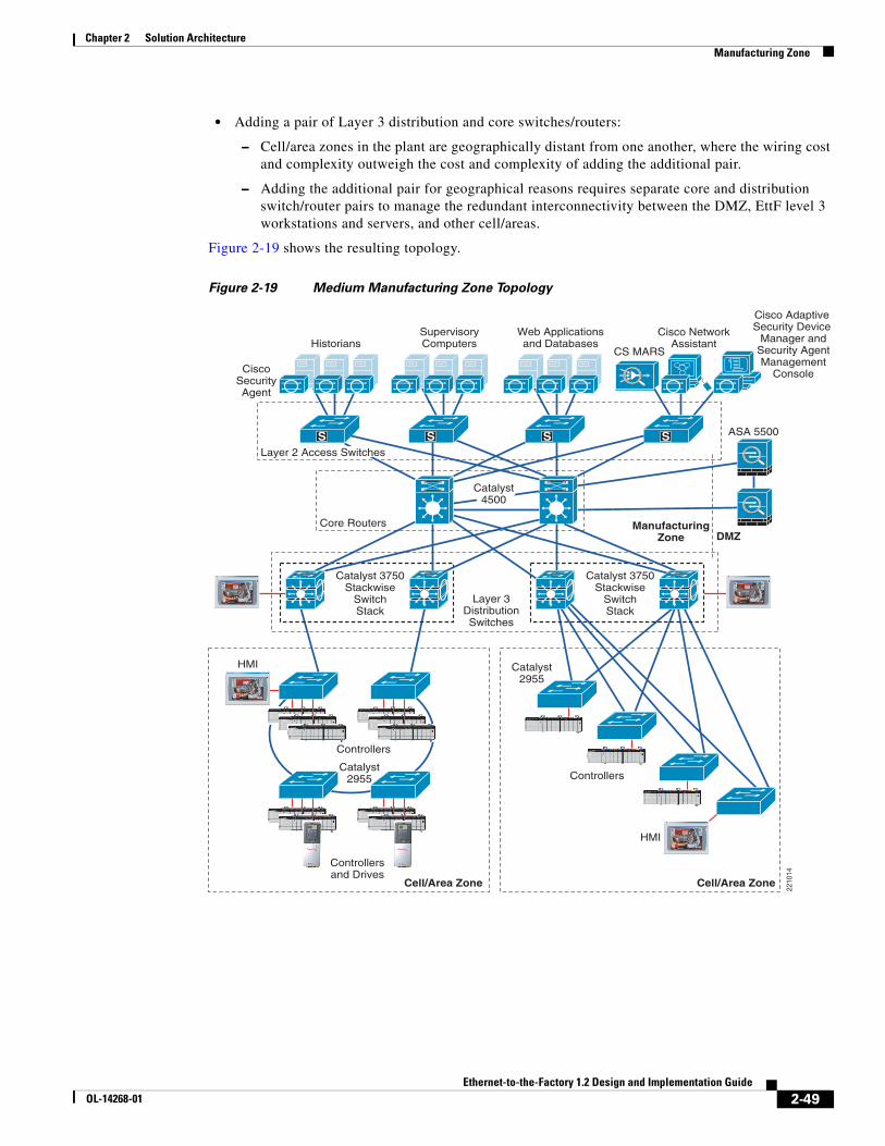
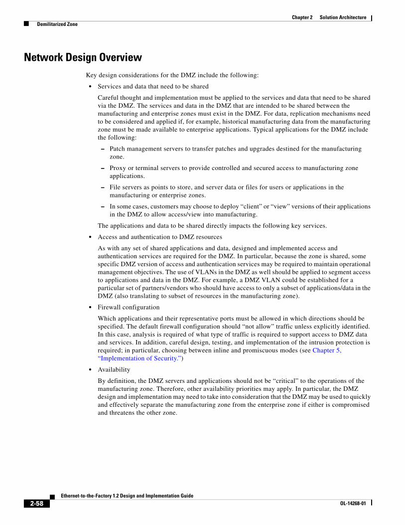
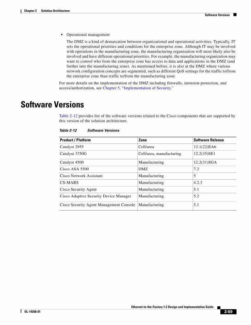
Network Design OverviewThe sections above outline the following key requirements for a network design:
• Endpoints connected to a network
• Flow of information between the various endpoints
• Topology of the network (where everything is located)
This section outlines the key technical considerations in designing a cell/area network, including the following:
• Logical segmentation
• Availability
• Multicast management
• Traffic management via quality of service (QoS)
• Security
Logical Segmentation
Logical segmentation is the process of outlining which endpoints need to be in the same LAN. Segmentation is a key consideration for a cell/area network. Segmentation is important to help manage the real-time communication properties of the network, and yet support the requirements as defined by the network traffic flows. Security is also an important consideration in making segmentation decisions. A security policy may call for limiting access of factory floor personnel (such as a vendor or contractor) to certain areas of the production floor (such as a functional area). Segmenting these areas into distinct VLANs greatly assists in the application of these types of security considerations.
In fact, there are competing objectives. On one hand, by the assumptions made for this design guide, all Level 0–2 devices that need to communicate multicast I/O between each other must be in the same LAN. On the other hand, the smaller the VLAN, the easier it is to manage and maintain real-time communications. Real-time communications are harder to maintain as the number of switches, devices, and the amount of network traffic increase in a LAN.
Table 2-6 Cell/Area Topology—Advantages and Disadvantages
Key Concerns Topology to Use
• Highly available network with minimal convergence
• High performance network with minimal bottlenecks
• Straightforward network design
Redundant star
• Cabling complexity is a major concern
• Highly available network is important
• Cost is important
Ring
• Cost and simplicity over availability and performance Trunk-drop
2-26Ethernet-to-the-Factory 1.2 Design and Implementation Guide
OL-14268-01
Chapter 2 Solution Architecture Cell/Area Zone
Note Cisco therefore recommends that customers strive to design smaller LANs or VLANs, while recognizing that the traffic patterns of industrial automation and control systems may make this difficult.
There are many approaches to segmenting a network. Production facility networks can be divided by functional sections of the factory floor (see #1 in Figure 2-11), product lines (see #2 in Figure 2-11), and traffic type (for example, I/O, PAC-to-PAC, and explicit traffic). To achieve the goal of minimizing VLAN sizes, a mixture of all three may be used.
Figure 2-11 Sample Factory Floor—Brewing and Bottling
Segmentation can be achieved though via the following two key mechanisms in the cell/area network:
• Physical—Use of separate cabling and Layer 2 access switches to achieve segmentation
• VLAN (802.1Q)—Use of the VLAN protocol to achieve a VLAN that can be implemented on the same physical infrastructure
Physical segmentation is a very common approach in current Ethernet implementations, but is applied to an extreme. For example, a common approach in current Ethernet deployments is to physically separate I/O traffic from explicit traffic and not to connect the I/O traffic to any interconnected Layer 3 distribution switch. In these cases, a PAC has separate network connections to each network, and the only means to communicate between the two networks is over the backbone of the PAC. The I/O network is therefore reachable only via the PAC backplane that processes only CIP traffic. (See Figure 2-12.)
Regular Brew
2209
80
Filling
Packaging
Office/Data Center
RawMaterial
FinishedGoods
1 2
Shipping
Dark Brew
Brewing
2-27Ethernet-to-the-Factory 1.2 Design and Implementation Guide
OL-14268-01
Chapter 2 Solution Architecture Cell/Area Zone
Figure 2-12 CIP Gateway Configuration Example
The effects of this include the following:
• Devices on subnet #2 are not accessible via non-CIP protocols (such as SNMP or HTTP), limiting overall interconnectivity.
• PAC was not designed to route/switch traffic, and may introduce significant delays when used in this manner.
• Network-based services (such as security, management, IP address allocation, and so on) must either be replicated in each network or are not available.
• Increased costs occur because the available network resources in subnet #1 (for example, open ports) are not available in subnet #2.
Although physical segmentation dedicates network resources to these various traffic types and helps increase the level of certainty that the traffic receives sufficient network resources, Cisco recommends that these networks be at least connected to Layer 3 switches so as to enable interconnectivity via other methods than the PAC. Additionally, Cisco recommends that customers consider other ways (for example, application of QoS) to ensure that critical network traffic (such as implicit I/O) receives appropriate network performance.
Note Cisco recommends the use of VLANs in addition to any physical segmentation, and that all cell/area LANs be connected to Layer 3 distribution switches to maintain connectivity.
VLANs offer the following features:
• Broadcast control—Just as switches isolate collision domains for attached hosts and forward only appropriate traffic out a particular port, VLANs refine this concept further and provide complete isolation between VLANs. A VLAN is a bridging domain, and all broadcast and multicast traffic is contained within it.
• Security—VLANs provide security in two ways:
– High-security users can be grouped into a VLAN, possibly on the same physical segment, and no users outside of that VLAN can communicate with them.
– Because VLANs are logical groups that behave like physically separate entities, inter-VLAN communication is achieved through a router. When inter-VLAN communication occurs through a router, all the security and filtering functionality that routers traditionally provide can be used because routers are able to look at Layer 3 information. In the case of non-routable protocols, there can be no inter-VLAN communication. All communication must occur within the same VLAN.
• Performance—The logical grouping of users allows, for example, an engineer making intensive use of a networked CAD/CAM station or testing a multicast application to be assigned to a VLAN that contains just that engineer and the servers he or she needs. The work of this engineer does not affect
2209
81
Subnet #1 (ie: HMI)
NIC
NIC
Subnet #2 (ie: I/O)
2-28Ethernet-to-the-Factory 1.2 Design and Implementation Guide
OL-14268-01
Chapter 2 Solution Architecture Cell/Area Zone
the rest of the engineering group, which results in improved performance for the engineer (by being on a dedicated LAN) and improved performance for the rest of the engineering group (whose communications are not slowed down by the single engineer using the network).
• Network management—The logical grouping of users, divorced from their physical or geographic locations, allows easier network management. It is no longer necessary to pull cables to move a user from one network to another. Adds, moves, and changes are achieved by configuring a port into the appropriate VLAN. Expensive, time-consuming recabling to extend connectivity in a switched LAN environment is no longer necessary because network management can be used to logically assign a user from one VLAN to another.
For more background information or VLANs, see the following:
• VLANs and VLAN trunking— http://www.cisco.com/en/US/partner/tech/tk389/tk689/tsd_technology_support_protocol_home.html
• LAN switching and VLANs— http://www.cisco.com/en/US/tech/tk1330/tsd_technology_support_technical_reference_chapter09186a008075983b.html
Any end device to be connected to multiple VLANs typically requires multiple network interface cards (NICs) available to the device. For example, controllers can have multiple NIC cards installed because of their modularity, and therefore have direct Layer 2 access to multiple VLANs. This may also be a consideration in the segmentation of the network.
Availability
Depending on the topology selected, various availability options can be designed into the network. If a topology is chosen with resiliency (for example, redundant star or ring), some form of network protocol is required to eliminate loops in the network. Loops are created when Layer 2 network devices are connected with multiple paths to reach the same destination. If left unmanaged, loops can cause serious network issues by creating broadcasts storms (messages continuously passed around the network) that eventually disrupt network service. Both standard and proprietary protocols have been developed to manage the loops and to react to connection losses by maintaining a consistent network.
The protocols identify (either manually or automatically) one or more connections to be virtually turned off to eliminate loops. When a connection is lost, the protocols must recognize the disruption and re-activate a closed connection to restore network viability. The speed at which a network protocol recognizes the disruption, opens a closed connection to restore network interconnectivity, and resumes normal network services is called the convergence time. During the convergence time, some portion of the traffic is dropped by the network because inter-connectivity does not exist. If the convergence time is longer than the cycle time in the industrial automation and control system, the systems on the affected portion of the network may begin to stop operating and bring parts of the factory floor to a halt. Thus, production and control engineers may decide that the additional cost and complexity of a resilient network may not provide sufficient value because they cannot recover in sufficient time to avoid disruption.
2-29Ethernet-to-the-Factory 1.2 Design and Implementation Guide
Note Although network convergence may not be fast enough to ensure industrial automation and control system uptime, Cisco recommends the use of resilient network topologies because they allow the manufacturing operations to continue when industrial automation and control systems are re-started without waiting on lost connections to be restored.
As mentioned, there are standard and proprietary protocols to manage resilient network topologies. The standard protocols are based on STP, which implements the 802.1D IEEE algorithm by exchanging Bridge Protocol Data Unit (BPDU) messages with other switches to detect loops, and then removes the loop by shutting down selected bridge interfaces. This algorithm guarantees that there is only one active path between two network devices. RSTP, based on IEEE 802.1w, is an evolution of the STP 802.1D standard and provides for faster spanning tree convergence after a topology change. The standard also includes features equivalent to Cisco PortFast, UplinkFast, and BackboneFast for faster network reconvergence.
For resilient network technologies and customers who want to either implement multi-vendor environments or to rely on standard technologies, Cisco recommends using RSTP in the network.
For more information on Spanning Tree Protocol and related technologies, see the Spanning Tree Protocol Introduction at the following URL: http://www.cisco.com/en/US/partner/tech/tk389/tk621/tsd_technology_support_protocol_home.html
Multicast Management
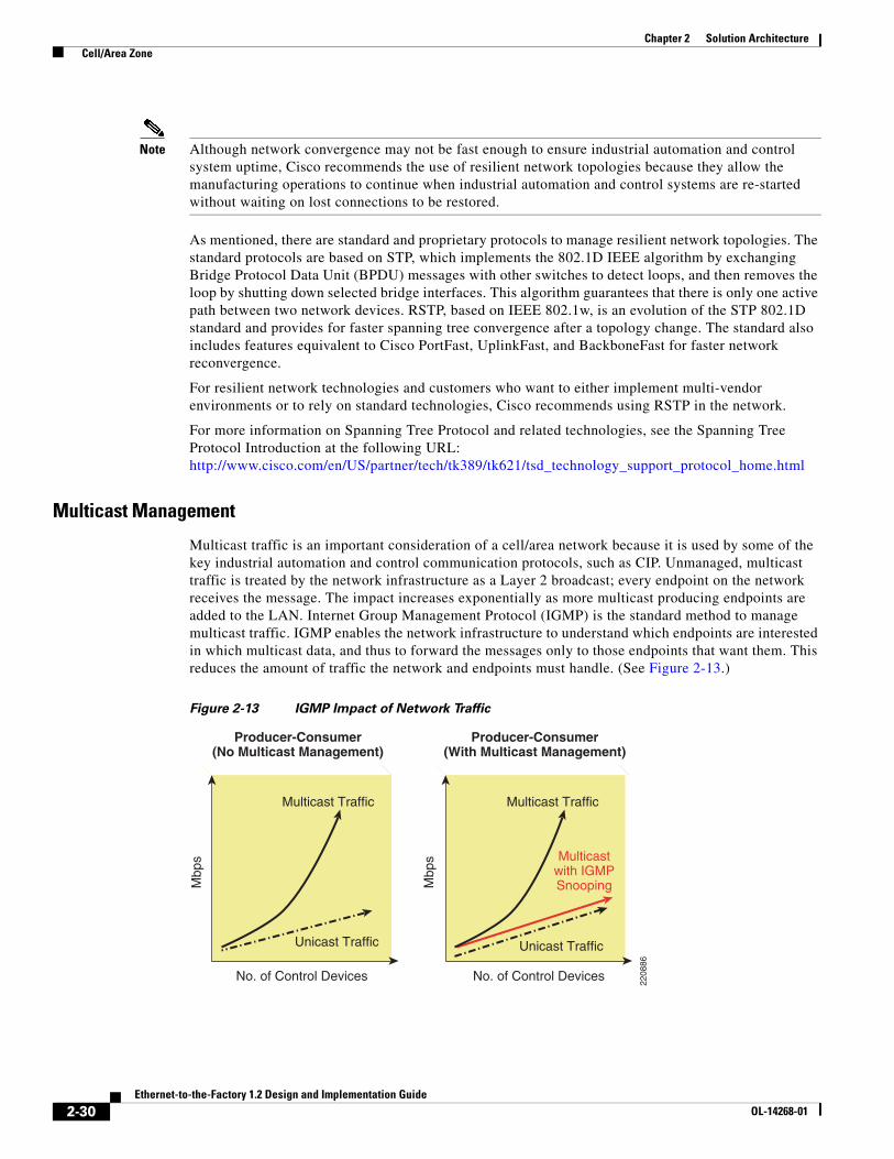
Multicast traffic is an important consideration of a cell/area network because it is used by some of the key industrial automation and control communication protocols, such as CIP. Unmanaged, multicast traffic is treated by the network infrastructure as a Layer 2 broadcast; every endpoint on the network receives the message. The impact increases exponentially as more multicast producing endpoints are added to the LAN. Internet Group Management Protocol (IGMP) is the standard method to manage multicast traffic. IGMP enables the network infrastructure to understand which endpoints are interested in which multicast data, and thus to forward the messages only to those endpoints that want them. This reduces the amount of traffic the network and endpoints must handle. (See Figure 2-13.)
Figure 2-13 IGMP Impact of Network Traffic
2208
86
No. of Control Devices
Multicast Traffic
Unicast Traffic
Mbp
s
No. of Control Devices
Mbp
s
Producer-Consumer(No Multicast Management)
Producer-Consumer(With Multicast Management)
Multicastwith IGMPSnooping
Multicast Traffic
Unicast Traffic
2-30Ethernet-to-the-Factory 1.2 Design and Implementation Guide
Note Cisco recommends that the network infrastructure be configured to manage multicast traffic. Ethernet switches should be configured to perform IGMP snooping. When IGMP snooping is enabled, the switch listens to IGMP traffic and develops a table that lists the multicast groups and the end devices. Thus, when a multicast packet is received, the switch forwards it only to end devices that want it. In addition, the Layer 3 distribution switch where the LAN is connected should be configured to perform the IGMP Querier function.
Although the number of multicast addresses in a VLAN or subnet is not typically an issue, it is a consideration under certain scenarios. EtherNet/IP devices can support up to 32 multicast addresses. Typically, however, an EtherNet/IP device uses a single multicast addresses. PACs can potentially use more for doing peer communications, but that may also be alleviated by choosing unicast messaging (an option in recent RA firmware updates). This is important because the network infrastructure has limits on the number of multicast addresses that can be supported. For example, the Catalyst 2955 can handle up to 256 multicast address. Unless steps are taken to use more multicast address than normal, these limits do not come into play. It is theoretically possible to configure a VLAN with nine or more EtherNet/IP devices to overrun the number of multicast addresses that the Catalyst 2955 switches can handle. This can be avoided using standard EtherNet/IP configuration guidelines. The impact of overrunning the switch multicast address space is that the multicast messages are treated as broadcast, introducing more traffic than necessary.
In this version of the solution architecture, multicast packets do not mix with enterprise or IT traffic via DMZ segmentation. If they did, there is the distinct potential of redundant use of multicast group addresses that would lead to disruptions in both the industrial automation and control system and the relevant IT application. For this and many other reasons, this solution architecture recommends a demilitarized zone (DMZ) between the manufacturing and enterprise zone to ensure that industrial automation and control multicast traffic and IT-driven multicast traffic remain separate.
For information on IP multicasting, visit Cisco Technology Support at the following URLs:
For more information on configuring and implementing IGMP, see Chapter 4, “Implementation of the Cell/Area Zone .”
Quality of Service
Quality of service (QoS) refers to control mechanisms that can provide various priorities to different users or data flows, or guarantee a certain level of performance to a data flow in accordance with requests from the application program. QoS guarantees are important if the network performance is critical, especially for real-time industrial automation and control systems.
Note Cisco recommends the application of QoS to the critical CIP-based implicit I/O as well as the explicit traffic generated by industrial automation and control systems.
As seen in Traffic Flows, page 2-18, non-CIP traffic (such as Internet HTTP) is very likely on any industrial automation and control network. The industrial automation and control devices can support various traffic types natively, and certain functions (for example, monitoring) are implemented using common protocols. As well, EttF level 3 workstations and servers in the manufacturing zone produce
2-31Ethernet-to-the-Factory 1.2 Design and Implementation Guide
traffic of various types that may mix with the cell/area traffic. In addition, in future versions of this architecture, Cisco believes that manufacturers will want to take advantage of the openness that standard networks provide to introduce other services into the manufacturing zone without sacrificing the performance required by the industrial automation and control systems. QoS will be a key mechanism to achieve this goal.
Unfortunately, at the time of this writing, the ODVA is still working on a set of QoS specifications for EtherNet/IP traffic. Cisco therefore has decided not to add specific design and implementation guidelines at this time. Design and implementation guidance based on the ODVA QoS specifications will be produced in later phases of this solution architecture. Until such time as these specifications are designed and tested, Cisco recommends that detailed network design and analysis be completed with the introduction of QoS in an industrial Ethernet network.
For more information on QoS, see the following URLs:
• Quality of Service— http://www.cisco.com/en/US/tech/tk1330/tsd_technology_support_technical_reference_chapter09186a0080759886.html
An overall security approach is presented in Chapter 5, “Implementation of Security.” The security design considerations for the cell/area network include the following:
• Port configuration (including MAC filtering, limited ACL configurations, QoS Trust)
• Infrastructure protection (hardening from a security perspective) of the network infrastructure to prevent unauthorized access
• Layer 2 security—Networking services can be disrupted through attacks on the protocols and standards to which they adhere. Layer 2 security protects the network services from attacks on the key protocols, including the following:
– Quality of service (QoS)
– Address Resolution Protocol (ARP)
– Rapid Spanning Tree Protocol (RSTP)
– Dynamic Host Configuration Protocol (DHCP)
– MAC address flooding
• Monitoring of network infrastructure administration data (syslogs and SNMP)
• VLANs for isolation
2-32Ethernet-to-the-Factory 1.2 Design and Implementation Guide
Chapter 2 Solution Architecture Manufacturing Zone
Manufacturing Zone
OverviewThe primary function of the manufacturing zone is to separate the services and applications that are critical to operating the factory floor from the rest of the enterprise, most importantly the industrial automation and control systems. The manufacturing network represents all the critical industrial automation and control systems required to operate the factory floor. These are the systems and applications insulated from the enterprise zone by the DMZ. This insulation not only provides security to both the enterprise and manufacturing zones, but may also represent an organization boundary where IT and manufacturing organizational responsibilities interface. By definition, the cell/area networks described above are part of the manufacturing zone. In fact, most manufacturing zones contain many cell/area zones. Key functions and features of the EttF architecture for the manufacturing network include the following:
• Interconnecting the various cell/area networks
• Integrating the level 3 site manufacturing systems
• Providing network management and security services to the Level 0–3 systems and devices
• Endpoint protection
Note that Cisco recommends that customers carefully consider which applications and services are considered part of the manufacturing zone. Key points to consider include the following:
• How long can operations continue without these services?
• Must this service be configured specifically for the manufacturing zone?
• How does the application and data need to interface with the enterprise zone?
• What are the costs/complexities associated with either replicating or adding redundant services to the manufacturing zone that may also exist in the enterprise zone?
• What are the security risks involved with placing the application or service into other zones and subsequent modification to the traffic flows?
2-33Ethernet-to-the-Factory 1.2 Design and Implementation Guide
OL-14268-01
Chapter 2 Solution Architecture Manufacturing Zone
Table 2-7 lists some of the key applications and services to consider.
For the purpose of this solution architecture, Cisco placed the applications and systems listed above in the manufacturing zone.
After the set of applications and services for the manufacturing zone are determined, the design of the network can begin. The following are key considerations of the manufacturing zone that are applied in the following sections:
• Environmental—Most production facilities have controlled areas for certain types of applications and IT-related infrastructure. The EttF level 3 applications and systems of the manufacturing zone typically reside in these environments. This suggests that the environmental requirements of the cell/area network typically do not apply to the manufacturing zone network infrastructure. An exception exists where the distribution devices (Layer 3 switches or routers) may potentially need to reside closer to the cell/area networks and therefore meet certain levels of extended environmental tolerance.
• Real-time communications—Because the systems and applications are more similar to IT, there are not the same real-time communications considerations of the manufacturing zone as in the cell/area zone. Network availability is critical, but the sensitivity of the devices to network performance (for
Table 2-7 Key Applications and Services
Type Critical Optional
Manufacturing applications • Historian
• Asset management and security
• Production floor monitoring and reporting
• Industrial automation and control system management and maintenance
• Manufacturing execution system
Network and security management
• Network management
• Security management
• Security monitoring, analysis, and response
Common network-based Services
• Directory and domain services provide application security to manufacturing zone applications
• IP address allocation (for example, DHCP or BootP); if dynamic allocations services are used, this will be required
• Dynamic Name Services—Most industrial automation and control systems do not use dynamic names and use instead hard-coded IP addresses. If dynamic names are used, a DNS service is required and is likely separate from the IT services.
• Network Time Protocol (NTP) servers are required to coordinate clocks in various industrial automation and control systems, including to network infrastructure.
• Backup and restore—This function is commonly provided from the enterprise zone, and for disaster recovery considerations, moving critical data off-site should be considered.
2-34Ethernet-to-the-Factory 1.2 Design and Implementation Guide
OL-14268-01
Chapter 2 Solution Architecture Manufacturing Zone
example, latency and jitter) is significantly reduced because they tend to be standard IT servers and workstations. Essentially, latency and jitter can vary more widely without significant disruption to the applications and devices in this zone.
• Availability—Availability of the network services is critical. Although the applications and services in the manufacturing zone may be more tolerant than more variable real-time communications, it is crucial that they stay available to maintain the operations in the cell/area zone. Without the services of the manufacturing zone, the production floor would soon stop.
• Manageability—The systems and applications in the manufacturing zone are typically administered and maintained by people with a focus on production floor operations, not IT or network. Although more standard technologies will be applied to manage the network resources, they need to be easy to implement and use.
• Security—As more of the applications and systems are based on standard computing resources (workstations, servers, and common operating systems), they will be susceptible to the wider range of security risks for this equipment. Additionally, security functions will be applied in this zone to provide service to cell/area zones and other EttF level 3 components and applications.
ComponentsThe manufacturing zone consists of the following (see Figure 2-14):
• EttF level 3 applications, servers, and workstations
• Depending on size and complexity, Layer 2 access switches to connect the EttF level 3 components
• Layer 3 switching and routing network infrastructure
• Network management applications
• Security management applications
• Endpoint security agent for endpoints with a common operating system (Linux and Microsoft)
2-35Ethernet-to-the-Factory 1.2 Design and Implementation Guide
OL-14268-01
Chapter 2 Solution Architecture Manufacturing Zone
Figure 2-14 Manufacturing Zone Overview
This document does not provide guidance about the selection design or the implementation of the actual EttF level 3 industrial automation and control equipment, or the media used to connect the devices and switches. The equipment included in the test lab that was used to validate the overall solution is listed.
Cisco included components for the following in this zone:
• Optional Layer 2 access switches
• Layer 3 switching or routers
• Network management application
• Security management, analysis, and response applications
• Endpoint security for standard operating system workstations and servers (for example, Microsoft Windows and Linux)
The key considerations for the components in this zone are described in the following sections.
2210
72
HMI
HMI
Catalyst2955
Controllers
Historians
Layer 3 Switchor Router
CiscoSecurityAgent
SupervisoryComputers
Web Applicationsand Databases
EttF-Level 3Workstations and Servers
CiscoNetworkAssistant
Cisco SecurityManagement
CS MARS
DMZ
ASA 5500
ManufacturingZone
Cell/Area ZoneDrive Cell/Area Zone
Controllers
Catalyst2955
Catalyst 3750Stackwise
SwitchStack
2-36Ethernet-to-the-Factory 1.2 Design and Implementation Guide
OL-14268-01
Chapter 2 Solution Architecture Manufacturing Zone
Cost
Although cost is always a consideration in production facilities, the applications and devices in this zone will tend not to be replicated as often as, for example, the Layer 2 switches found in cell/area zones. Therefore, there is not the similar managed versus unmanaged question as in the cell/area zone; managed equipment is used by default.
Physicality and Environmental Considerations
As stated above, the environmental considerations for this zone are less critical because it is assumed that controlled environments will exist for the equipment.
It is recognized, however, that there is a need in some production floor environments for the Layer 3 switching/routing functions to exist in an industrial packaging and to operate in the same conditions. Cisco does not currently offer these capabilities in an industrial packaging.
Performance and Real-time Communications
Although not quite as critical as the cell/area zone, it is critical for the network infrastructure to support real-time communications functions. The critical implicit and explicit traffic may traverse the manufacturing zone infrastructure. Note the following considerations:
• Bandwidth supported on Layer 3 switches and router ports (typically up to 1 Gbps) and any Layer 2 access ports (typically up to 100 Mbps) and uplink ports (typically up to 1 Gbps)
Endpoint security has also been included in this solution architecture. As such, consider the overall network and system performance the application has on the system on which it is running.
Regarding Cisco security management, analysis, and response (MARS), a key performance factor is the number of events and amount of network traffic that a device can support.
Regarding network management, the key performance criteria are the number and types of network infrastructure devices that can be supported.
Availability
The network infrastructure availability is directly related to overall availability of the industrial automation and control system. Thus, availability considerations are important and include the following:
• Availability options available (for example, Hot Standby Router Protocol) and failover options (for example, stackable switch technology)
• Mean time to break/fix ratings
• Storm control and rate limiting to protect the network and other devices from out-of-control network communications
• Support for routing convergence protocols
2-37Ethernet-to-the-Factory 1.2 Design and Implementation Guide
OL-14268-01
Chapter 2 Solution Architecture Manufacturing Zone
Manageability
Network and security management services and endpoint security are a part of this zone. These applications must be relatively easy to install, configure, and operate. They must relax the level of expertise and knowledge required by the production floor personnel to maintain and operate the production floor network. Key considerations for this equipment include the following:
• Intuitive web-based interfaces via secure connections (for example, HTTPS)
• Ease of installation and upgradeability
• Ease of configuration and auto-detect functions to find and interface with appropriate network/security infrastructure
• Intuitive summarization of network and security status with easy-to-use drill-down features for problem solving
• Ability to develop templates for security/network management and to apply those throughout the manufacturing zone
• Built-in knowledge repositories to assist production and control engineers during problem resolution
• Ability to securely allow access to appropriate operational or maintenance personnel
In addition to the actual network and security management applications, there are also manageability considerations for the network infrastructure, especially the Layer 3 switches and routers. Basic management functions such as initial configuration, break/fix, and monitoring need to be relatively easy. Key considerations include the following:
• SNMP capable—Most network device vendors support management via the Simple Network Management protocol (SNMP) v3.
• Ease of installation, setup and maintenance—The network infrastructure should be easy to install, set up, and maintain with key basic functions supported by the key applications production floor user applications; that is, the industrial automation and control applications.
• Warranty and support options for the expected lifetime of the equipment.
• Web-based, intuitive user interfaces.
• Application interfaces (for example, XML support) to interface with other applications.
• CIP support—The ability for the equipment or application to interface with the industrial automation and control systems for basic management and monitoring functions greatly eases overall use and ongoing maintenance.
Security
The Manufacturing zone contains a number of security components including the security monitoring and analysis, security management, and endpoint security. Beyond these aspects, the key security considerations for each network component within the manufacturing zone include the following:
• Access control lists (ACLs) allow users to configure security policies into a switch.
• Support for VLANs.
• Secure Shell (SSH) switch OS access.
• SNMPv3 support for encryption of this important protocol used to manage and monitor the network infrastructure.
• Port-based security to prevent access from unauthorized devices.
2-38Ethernet-to-the-Factory 1.2 Design and Implementation Guide
OL-14268-01
Chapter 2 Solution Architecture Manufacturing Zone
• MAC address notification.
• Port Security via MAC address identification
• Control plane policing for switches and routers—protection of the Layer 3 protocols used to support various network services.
• Authentication and access servers to manage network and application security.
For more on network security considerations, see Security Design for the Manufacturing Zone, page 5-19.
2-39Ethernet-to-the-Factory 1.2 Design and Implementation Guide
OL-14268-01
Chapter 2 Solution Architecture Manufacturing Zone
Component Summary
For the purpose of testing, the products listed in Table 2-8 were part of the manufacturing zone.
Table 2-8 Components
Role Product/Platform Software Release Comments
Distribution switch Cisco Catalyst 3750 Series
• Cisco Catalyst 3750G-24TS-24 Ethernet 10/100/1000 ports and four Small Form-Factor Pluggable (SFP) uplinks
12.2(31)SGA Optional in medium-to-large operations to provide core networking functions
Security monitoring, analysis, and response
Cisco Security MARS 20R
4.2.3 Monitors security events from switches, routers, firewalls, and endpoint agents
Endpoint protection CSA 5.1 Security protection for standard OS devices
2-40Ethernet-to-the-Factory 1.2 Design and Implementation Guide
OL-14268-01
Chapter 2 Solution Architecture Manufacturing Zone
Switching and Routing
The Catalyst 3750 switch was selected because it provides the best mix of features, performance, and cost for small-to-medium production facilities. Key considerations included the following:
• Lower cost base
• Already established in this role at a number of customer accounts
• Provides sufficient Layer 3 switching/routing features for most small-to-medium facilities
• Provides easy-to-configure resiliency and scalability with the StackWise connectivity to form a “virtual” switch
• Flexibility to grow with the production facility by adding additional stackable units
For more information, see the following URL: http://www.cisco.com/en/US/products/hw/switches/ps5023/index.html
Figure 2-15 shows the Cisco Catalyst 4500 switches.
Figure 2-15 Cisco Catalyst 4500 Switches
An option that was strongly considered and that is believed to be a good option for larger production facilities is the Catalyst 4500, for the following reasons:
• Capacity or scalability is a concern; for example, when integrating a large number of cell/area networks and EttF level 3 workstations and servers
• Upgradeable processor and interfaces for longer-term viability
• Better failover features for availability; for example, in-service upgradeability
For more information, see the following URL: http://www.cisco.com/en/US/products/hw/switches/ps4324/index.html
Firewall configuration and management
Cisco Adaptive Security Device Manager 5.2 Firewall and intrusion protection services. Manages traffic flows between manufacturing, DMZ, and enterprise zones.
Chapter 2 Solution Architecture Manufacturing Zone
For large and extremely large manufacturing environments, the Catalyst 6500 should also be considered, but was not considered for this version of the architecture. For more information, see the following URL: http://www.cisco.com/en/US/products/hw/switches/ps4324/index.html
Figure 2-16 shows the CS-MARS.
Figure 2-16 CS MARS
Security Monitoring, Analysis, and Response
The entry-level Cisco Security MARS appliance was selected. A wide variety of appliances is available that support increasing levels of events and network flow. For more information, see the CS MARS product overview at the following URL: http://www.cisco.com/en/US/partner/products/ps6241/index.html
A wide variety of devices that support increasing levels of events are available.
Additionally, for customers interested in deploying in a number of manufacturing sites, global controller units are also available, although this version of the solution architecture does not cover this case.
Endpoint Security
Cisco recommends the deployment of Cisco Security Agent on the workstations and servers running common operating systems.
For more information, see the CSA product website at the following URL: http://www.cisco.com/en/US/partner/products/sw/secursw/ps5057/index.html
Network Management
The Cisco Network Assistant (CNA) is recommended to perform the network management functions for the manufacturing zone. CNA supports up to 40 Cisco network devices, which meets the needs of the small-to-medium manufacturer. Key features include the following:
• No cost, downloadable at http://www.cisco.com/go/cna
• Getting started with CNA— http://www.cisco.com/en/US/partner/products/ps5931/products_getting_started_guide_book09186a00802b3c41.html
CiscoWorks is suggested as an option for more sophisticated and involved network management, such as the following:
• Multi-vendor network infrastructure must be supported (via SNMP)
• Cross-manufacturing site management is a current or future requirement
• More than 40 network devices at one site need to be managed
CiscoWorks is a portfolio of network management. For more information, see the following URL: http://www.cisco.com/en/US/products/sw/netmgtsw/index.html
Security Management
Cisco recommends the deployment of the Cisco Adaptive Security Device Manager to manage the firewalls in the DMZ. Key features include the following:
For more information, see the following URL: http://www.cisco.com/en/US/products/ps6121/index.html
Cisco recommends the deployment of CiscoWorks Management Center for CSA to manage the CSA and the endpoint security solution. Key features include the following:
• Centralized monitoring and management of CSA endpoint instances
• Role-based, web browser, intuitive user interface
• 20 pre-configured default policies
• Allows users to work in an IDS mode for learning and alerting (versus blocking)
• Allows for customizations to the policies and easy deployment to the agents
For more information, see the following URL: http://www.cisco.com/en/US/products/sw/cscowork/ps5212/index.html
For customers that are interested in more comprehensive security management solutions, Cisco recommends considering Cisco Security Manager, which incorporates the above applications. For more information, see the following URL: http://www.cisco.com/en/US/products/ps6498/index.html.
2-43Ethernet-to-the-Factory 1.2 Design and Implementation Guide
Chapter 2 Solution Architecture Manufacturing Zone
Traffic Flows—Manufacturing ZoneThe traffic flows in a manufacturing zone resemble those of a de-centralized client-server environment. Many of the EttF level 3 workstations, applications, and servers do the following:
• Send detailed scheduling, execution, and control data to controllers in the various cell/area zones
• Collect information from the cell/area networks for historical and audit purposes
• Provide site-level operations management
• Perform application, network, and security administration and maintenance function for the overall manufacturing zone, including the following:
– Patch launch server
– Terminal services
– File server
– Domain and Lightweight Directory Access Protocol (LDAP) services
– Network and security management
• Production reporting services (for example, cycle times, quality index, predictive maintenance) available to manufacturing zone and via the DMZ and enterprise zone users
• Provide data and services that will be shared through the DMZ to applications or users in the Enterprise zone
Traffic flows are outlined from two perspectives:
• Industrial automation and control applications (for example, historian, asset management, automation and control security, reporting)
• Network and security management
As with the cell/area zone, traffic from the network infrastructure protocols (for example, ARP and STP) is not represented.
2-44Ethernet-to-the-Factory 1.2 Design and Implementation Guide
OL-14268-01
Chapter 2 Solution Architecture Manufacturing Zone
Figure 2-17 and Table 2-9 show the manufacturing zone traffic flow.
Figure 2-17 Manufacturing Zone Traffic Flow—Industrial Automation and Control Application
Table 2-9 Manufacturing Zone Traffic Flows
Ref. # From To Description Protocol Type Port(s)
1 Server Cell/area device
CIP diagnostic, configuration, information, uploads/downloads, and identification data.
Example:
a. FactoryTalk Historian or FactoryTalk View SE requests data
b. Controller replies with data
EtherNet/IP
TCP/UDP 44818
2 Client/ server
Client/ server
FactoryTalk Transaction Manager RPC TCP 400–402
HMI HMI
DrivesControllerController
Historian,RS AssetSecurity
SupervisoryComputers
RS View SE Server,FactoryTalk Server
and SQL Server
Network and SecurityManagement Tools
(e.g. CAN, CS MARS)
Catalyst2955
FactoryTalk ClientDCOM Client
RS View SE Client,BizWare Client or SMTP Server
DMZ
220963
Catalyst2955
2b
2a 2a
4
9
1
7
7,10,11
5,6
2b
Catalyst 3750Stackwise
SwitchStack Manufacturing
Zone
3,8
Engineering Laptop(RS View)
ASA 5500
Cell/Area Zone Cell/Area Zone
2-45Ethernet-to-the-Factory 1.2 Design and Implementation Guide
OL-14268-01
Chapter 2 Solution Architecture Manufacturing Zone
In summary, the traffic flow of the industrial automation and control application data depends on where the various clients and servers are placed within the framework (for example, DMZ or manufacturing zone) to best support the required integration between the enterprise and manufacturing zones.
3 Client/ server
Client/ server
FactoryTalk Metrics—Production server RPC TCP 4120
FactoryTalk Metrics—Server manager RPC TCP 4121
FactoryTalk Metrics—PlantMetrics server RPC TCP 4122
FactoryTalk Metrics—Task manager RPC TCP 4123
FactoryTalk Metrics—Schedule server RPC TCP 4124
FactoryTalk Metrics—Schedule CTP server RPC TCP 4125
4 Client/ server
Client/ server
FactoryTalk Service Platform support DCOM Endpoint mapper
TCP 135
DCOM TCP dynamic (1024-65535+)
5 Client/ server
Client/ server
FactoryTalk—Object RPC rnaprpc TCP 1330
FactoryTalk—Service control rnaserv TCP 1331
FactoryTalk—Server health ranserverping
TCP 1332
FactoryTalk—Directory server file transfer rnadirft TCP 3060
FactoryTalk—Alarming server rnaalarming
TCP 6543
FactoryTalk—Event multiplexor TCP 7600
FactoryTalk—Event server TCP 7700
FactoryTalk—Directory server TCP 7710
FactoryTalk—License server TCP 27000
6 Client/ server
Client/ server
FactoryTalk View SE—HMI server TCP 7720
FactoryTalk View SE—Server framework TCP 7721
FactoryTalk View SE—HMI Activation TCP 7722
FactoryTalk View SE—Historical data log reader TCP 7723
7 Client/ server
Client/ server
FactoryTalk AssetCentre TCP 1433
8 Client/ server
Client/ server
FactoryTalk AssetCentre RPC TCP 135
9 Server Client-browser
FactoryTalk and RSView 32 HTTP TCP 80
10 Server Client-browser
FactoryTalk Metrics—Reports and server manager HTTP TCP 8080 8081
11 Client Mail server FactoryTalk Metrics, FactoryTalk Transaction Manager, FactoryTalk View—Mail for event notification
SMTP TCP 25
Table 2-9 Manufacturing Zone Traffic Flows (continued)
2-46Ethernet-to-the-Factory 1.2 Design and Implementation Guide
OL-14268-01
Chapter 2 Solution Architecture Manufacturing Zone
Topology Options OverviewAs the manufacturing zone is assumed to be installed in a controlled environment and not on the factory floor, the topology options are not going to be driven by the physical constraints of the factory floor, but rather the size of the environment to be supported. The various options range from a single pair of Layer 3 switches to a set of Layer 2 access switches and two (or more) sets of Layer 3 switches/routers for the large manufacturers by introducing separate access, distribution, and core networking services. Topology options include the following:
• Small manufacturing zone of up to 50 nodes
• Medium manufacturing zone of up to 200 nodes
• Large manufacturing zone of more than 200 nodes
Small Manufacturing Zone Topology
The small manufacturing zone includes a redundant pair of Layer 3 switches configured for redundancy (see Figure 2-18). All EttF level 3 devices are connected directly to the switches. A set of stacked 3750 Layer 3 switches can support from 23 (two 12-port switches) to 468 ports (maximum 9 switches and maximum 48 port devices), so this configuration can support a small manufacturer. In this version, the Layer 3 switches provide inter-VLAN and zonal routing functions as well as Layer 2 connectivity to EttF level 3 workstations and servers.
The small manufacturing zone essentially represents a collapsed core-distribution network routing services. This should suffice for small and many medium manufacturing facilities.
2-47Ethernet-to-the-Factory 1.2 Design and Implementation Guide
OL-14268-01
Chapter 2 Solution Architecture Manufacturing Zone
Figure 2-18 Small Manufacturing Zone Topology
Medium Manufacturing Zone Topology
The medium topology represents the separation of various network routing services and replication of these services to meet requirements in a larger production facility (see Figure 2-19). Although the small topology can easily support up to 200 Ethernet nodes, there are situations even in this type of node count that may require a more segmented topology. This topology differs from the small manufacturing topology as follows:
• Separate Layer 2 access switches to connect the EttF level 3 workstations and servers
• Additional pair of Layer 3 distribution switches for geographically distributed cell/area zones
• Additional pair of Layer 3 core routers to consolidate the traffic
Not all three of these topology enhancements need be implemented; each one could be added. Following are some considerations for each of the scenarios:
• Separate Layer 2 access switch:
– High-availability workstation or server environments may require redundant network connectivity to the workstations and servers. In these cases, Cisco recommends having a separate Layer 2 access switch for the configuration of the relevant protocols. For more information, see Server Farm Access Layer, page 3-9.
2210
13
HMI
HMI
Catalyst2955
Historians
CiscoSecurityAgent
SupervisoryComputers
Web Applicationsand Databases
Cisco NetworkAssistant
Cisco Adaptive SecurityDevice Manager and
Security AgentManagement Console
CS MARS
DMZ
ASA 5500
ManufacturingZone
Cell/Area Zone
Controllersand Drives
Cell/Area Zone
Controllers
Catalyst2955
Catalyst 3750Stackwise
SwitchStack
2-48Ethernet-to-the-Factory 1.2 Design and Implementation Guide
OL-14268-01
Chapter 2 Solution Architecture Manufacturing Zone
• Adding a pair of Layer 3 distribution and core switches/routers:
– Cell/area zones in the plant are geographically distant from one another, where the wiring cost and complexity outweigh the cost and complexity of adding the additional pair.
– Adding the additional pair for geographical reasons requires separate core and distribution switch/router pairs to manage the redundant interconnectivity between the DMZ, EttF level 3 workstations and servers, and other cell/areas.
Figure 2-19 shows the resulting topology.
Figure 2-19 Medium Manufacturing Zone Topology
S S
2210
14
Core Routers
HMI
HMI
Catalyst2955
Catalyst2955
Controllers
Controllers
HistoriansSupervisoryComputers
Web Applicationsand Databases
Cisco NetworkAssistant
Cisco Adaptive Security Device
Manager andSecurity AgentManagement
Console
CS MARS
ASA 5500
DMZ
Catalyst 3750Stackwise
SwitchStack
Catalyst 3750Stackwise
SwitchStack
ManufacturingZone
S S
Catalyst4500
Layer 3DistributionSwitches
Layer 2 Access Switches
CiscoSecurityAgent
Cell/Area Zone Cell/Area Zone
Controllersand Drives
2-49Ethernet-to-the-Factory 1.2 Design and Implementation Guide
OL-14268-01
Chapter 2 Solution Architecture Manufacturing Zone
Manufacturing Zone Topology Summary
Cisco does not have a specific recommendation between the small and medium options presented. The customer requirements, in particular scalability, geographical dispersion, and availability requirements, determine which option to choose.
Note that the medium option represents separating out the access, distribution, and core networking functions into distinct equipment. In the small version, all three are supported by the pair of Layer 3 switches. It is also possible that only the access or core functions will be separated out, which produces more variations.
Network Design OverviewThe sections above have outlined the following key requirements for a network design:
• Endpoints connected to a network
• Flow of information between the various endpoints
• Topology of the network (where everything is located)
The next sections outline the key technical considerations in designing a cell/area network, which include the following:
• Logical segmentation
• Availability
• Routing
• Traffic management via QoS
• Security
• Manageability
Logical Segmentation
Logical segmentation is important at this level, especially for the EttF level 3 workstations and servers. In the cell/area zone, it is important for endpoints that communicate implicit IO traffic to be in the same VLAN for traffic flow and real-time communications reasons. In the manufacturing zone, the key consideration for segmentation is security. Security policy may require that certain functions or roles have access to particular applications and services that reside in the manufacturing zone. In addition, the industrial automation and control applications (EttF level 3) may need access only to a subset of cell/area zones. A well-designed segmentation design greatly improves the ability to apply and maintain a security policy.
The following key functional areas are good candidates for segmentation:
• Industrial automation and control systems dedicated to particular functions in the factory floor (for example, a brewing control room)
• Security and network administration applications
As in the cell/area zone, a mixture of physical separation and VLANs is used to achieve segmentation.
In this context, there is one particular common practice that Cisco strongly discourages: “dual-homing”. Dual-homing is the concept of having key manufacturing zone workstations or servers installed with two network interfaces: one connected to the manufacturing zone and the other directly to the enterprise zone. Dual-homing facilitates the sharing of data and services between the two zones. This poses a
2-50Ethernet-to-the-Factory 1.2 Design and Implementation Guide
OL-14268-01
Chapter 2 Solution Architecture Manufacturing Zone
significant security risk because these workstations or servers typically are not secured as other devices can be, and are points of entry to the manufacturing zone for malicious activity to target. The Cisco solution architecture identifies a DMZ with firewall functions to safely and securely share data and services between these zones.
Availability
Because the cell/area inter-connect functionality exists in this zone, the high availability of the routing infrastructure is critical to the optimal performance of the manufacturing zone. This section describes design considerations for the following key manufacturing services:
• EttF level 3-Layer 2 connectivity
• Core routing and Layer 3 switching
• Network and systems management
• Endpoint security
Layer 2 Connectivity
The EttF level 3 workstations and servers are connected to LANs/VLANs. These VLANs also need to be designed with availability considerations. Cisco previously recommended that the redundant topology be applied; therefore, RSTP must be implemented in the Layer 2 networks to prevent network loops and to recover after the loss of a connection.
Core Routing and Layer 3 Switching Resiliency
Key availability considerations in routing and switching can be divided into hardware and device level considerations and network level considerations.
Device Level Resiliency
Device level resiliency refers to techniques that protect against any failure of a device node so that it can continue processing traffic with no or minimum disruption. The techniques relevant to the control network environment are shown in Table 2-10.
Table 2-10 Device Level Resiliency Design
Feature Description Supported PlatformsWhere to Apply in Industrial Ethernet Network
Redundant route processors (supervisors)
Active and standby supervisors operate in active and standby modes and provide a variety of redundancy mechanisms to handle failure scenarios. Requires redundant devices.
• Catalyst 4500
• Catalyst 3750—Virtual with StackWise
All
StackWise Uses stack interconnect cables to create a virtual switch fabric for stacks of the Catalyst 3750.
• Catalyst 3750
• N/A to Other Platforms
All
Redundant power supplies
Each system has dual power supplies so that the system operates normally upon failure of a power supply
• Catalyst 4500: Internal
• Catalyst 3750: External
• Catalyst 2955: External
All
Redundant fans Each fan tray has multiple fans Catalyst 4500 All
2-51Ethernet-to-the-Factory 1.2 Design and Implementation Guide
OL-14268-01
Chapter 2 Solution Architecture Manufacturing Zone
Line card online insert and removal (OIR)
New line cards can be added or removed without affecting the system or losing the configuration.
Catalyst 4500 All
Control Plane Policing (CoPP)
Prevents malicious traffic from flooding the CPU to the point that the switch can no longer forward packets and perform functions. Achieved by configuring a QoS filter.
Catalyst 4500 All
Nonstop Forwarding with Stateful Switchover (NSF with SSO)
Inter-chassis supervisor failover at Layers 2 through 4. Reduces the mean time to recovery (MTTR).
Catalyst 4500 Whatever Layer 3 routing takes place
In-Service Software Upgrade (ISSU)
Ranges from full image upgrades to granular; selective software maintenance can be performed without service impact across all Cisco IOS-based products.
Catalyst 4500
IOS Software Modularity
Minimizes unplanned time, If an error occurs in a modular process, the system determines the best recovery action. The recovery options include:
• Restart a modular process
• Switchover to standby supervisor
• Remove the system from the network
Allows a modular process to be patched and restarted without any downtime.
Catalyst 6500 All
Automatic software upgrade for Catalyst 3750 StackWise
The Master 3750 transfers the same version of code to the remaining switches in the stack. The upgrade includes
• Transfer the global configuration
• Apply default configuration
• Apply preconfigured configuration
Catalyst 3750 All
Generic Online Diagnostics (GOLD)
Online diagnostics to help ensure that a system that is booting up and a live system are healthy.
Catalyst 4500 and 3750: subset of GOLD
All
Configuration rollback
Capability to replace the current running configuration with any saved Cisco IOS configuration file
2-52Ethernet-to-the-Factory 1.2 Design and Implementation Guide
OL-14268-01
Chapter 2 Solution Architecture Manufacturing Zone
Network Level Resiliency
Network level resiliency refers to techniques that can route traffic around a failure point in the network. The techniques relevant to the control network environment are shown in Table 2-11.
Security and Network Management
The security and network management services are in the manufacturing zone for security considerations; they require access to critical network features. Therefore, they can be used to attack a system. The most secure location for these services is behind the firewall in the manufacturing zone.
These services are not typically critical to the operation of the plant floor. If they fail, services should be restored as soon as possible, but it is not likely that production will be directly impacted.
There are situations and environments where critical audit and control procedures may dictate that these systems be operational to maintain logs and audit trails of activity in the manufacturing zone. In this case, these applications may then require a higher level of availability, which can be achieved in various ways.
Although this solution architecture does not provide specific implementation guidance, key considerations to increase availability include the following:
• All workstations or servers with security or network management applications should be backed up, and scheduled testing of the integrity of the backup should be performed.
• Redundant servers or workstations capable of continuing operations should be deployed.
• Redundant network connectivity on the servers running the applications add a level of network resiliency.
Endpoint Security
CSA can be designed to operate in a managed or unmanaged mode. This solution architecture recommends a managed mode so as to better manage the security stance of the protected endpoints in the manufacturing zone. In the managed mode, CSA-protected endpoints communicate with the CSA Management Console (MC). If the CSA MC fails, CSA continues to operate (as if in unmanaged mode) until the service is re-established.
Table 2-11 Network Level Resiliency Design
Feature Description Supported PlatformsWhere to Apply in Industrial Ethernet Network
Link redundancy– dual homing
Sends packets to their destinations over a backup link of a network device when its primary link fails because of link breakage, or failure of an interface or line card. Determined by the L2 STP or a L3 routing protocol.
All routers and switches All
Hot Standby Router Protocol (HSRP)
Cisco proprietary redundancy protocol for establishing a fault-tolerant default gateway.
• Catalyst 4500
• Catalyst 3750—Virtual with StackWise
Wherever Layer 3 routing takes place
Incremental SPF Optimizations
Optimization of the OSPF algorithm to reduce computational load.
• Catalyst 4500—Internal
• Catalyst 3750—External
All
IP dampening Mechanism to suppress affects of excessive state changes (flapping).
Catalyst 4500 All
2-53Ethernet-to-the-Factory 1.2 Design and Implementation Guide
OL-14268-01
Chapter 2 Solution Architecture Demilitarized Zone
Routing
Routing is a key feature of the manufacturing zone. For more information on routing basics, see the following URL: http://www.cisco.com/en/US/tech/tk1330/tsd_technology_support_technical_reference_chapter09186a008075970b.html
Manageability
The following are key considerations for the availability of the network and security management functions:
• Scripting (security issues, troubleshooting, complex setup and recovery)
• Network sniffer and protocol analyzer; for example, Wireshark (formerly known as Ethereal) for basic network troubleshooting
Demilitarized ZoneThe enterprise zone and the manufacturing zone have different requirements, priorities, policies, and implications of incidents, but they should be able to share data and access systems and applications. The EttF solution architecture introduces the DMZ into the EttF architecture to provide logical segmentation between the enterprise and manufacturing zone. Systems and data that need to be accessed by both manufacturing and enterprise business systems reside in the DMZ, protecting information and accommodating the different security and operational requirements of these major zones. As a best practice, all traffic should terminate in the DMZ, eliminating direct traffic flow between the enterprise zone and the manufacturing zone.
The DMZ is a key aspect of the overall security approach for the EttF solution architecture. The DMZ is a strong form of logical segmentation between the manufacturing zones (and all that encompasses) and the enterprise zone (and via that the Internet). It is in the DMZ that firewall and intrusion protection solutions are introduced. These are applied to all traffic entering or exiting the DMZ, either to or from the manufacturing or enterprise zones. In addition, the concept of not allowing traffic to traverse the DMZ also adds the capability of setting clear access and authorization principles. For example, enterprise users can be forced to authenticate against manufacturing-specific security services to ensure that they have right to the services and data made available in the DMZ.
The DMZ is also a demarcation where different operational and security policies can be applied to meet objectives from various perspectives. For example, the DMZ demarks where QoS settings change. In addition, the DMZ also demarks where critical I/O traffic from the manufacturing zone stops and is not mixed with enterprise traffic. The DMZ can be used to apply different operational settings (for example, authorizations, configurations, monitoring, and so on) to allow different network operational models to exist between the manufacturing environment and the IT-managed enterprise. As a last resort, the DMZ is also a point where access can easily be shut off if issues or threats arise in a zone that threatens operations in other zones.
The DMZ is not a new concept, but is prevalent in enterprise networks where applications and data are shared with other enterprises or made available to the Internet. The concept and application of the DMZ between the enterprise and manufacturing zones is very similar to the DMZs applied at the Internet and enterprise interface. Those DMZs apply strong traffic control, in-depth packet inspection, and enforced authorization and authentication for privileged access.
2-54Ethernet-to-the-Factory 1.2 Design and Implementation Guide
Chapter 2 Solution Architecture Demilitarized Zone
The DMZ provides the following:
• Threat control and containment
• Area to safely and securely share applications and data
• Demarcation for organizational and responsibility reasons
Figure 2-20 shows the DMZ and related features.
Figure 2-20 DMZ and Related Features
2218
22
ACLs, Firewall, IPS
ASA 5500
Manufacturing Zone
DMZ
Catalyst2960
Terminal Servers,Patch Management,
AntiVirus, Historian Mirror,Web/Application Server
Catalyst 4500
Shared DMZ DesignBest Practices
Shared Applicationsand Data
DMZ
Enterprise Zone
2-55Ethernet-to-the-Factory 1.2 Design and Implementation Guide
OL-14268-01
Chapter 2 Solution Architecture Demilitarized Zone
ComponentsAs with the network infrastructure in the manufacturing zone, the DMZ components are assumed to be housed in environmentally-controlled locations, where the stringent factory floor physical constraints do not come into play. All DMZ components are not assumed to be “industrialized” or “ruggedized”.
The key components of the DMZ are the firewalls. The firewalls act as routers/switches between the manufacturing and enterprise zone, and provide in-depth, stateful packet inspection for firewall and intrusion detection.
Figure 2-21 shows the Cisco ASA 5520 switch.
Figure 2-21 Cisco ASA 5520
In addition, the DMZ also contains switching and routing domains where the servers that share data and applications exist. Cisco recommends deployment of the Catalyst 2960. For more details regarding the Catalyst 2960 Series Switches, see the following URL: http://www.cisco.com/en/US/products/ps6406/index.html
2-56Ethernet-to-the-Factory 1.2 Design and Implementation Guide
Chapter 2 Solution Architecture Demilitarized Zone
Topology Options OverviewOnly one topology was considered for this version of this guide. This topology includes the following:
• Single pair of firewalls, one operating in stand-by mode for high availability. Each firewall has a connection to the enterprise zone, manufacturing zone, and access switches of the DMZ.
• A pair of switches to provide Layer 2 access connectivity between the servers in the DMZ and the firewalls.
Figure 2-22 shows the DMZ topology.
Figure 2-22 DMZ Topology
A topology that was not tested as part of the development of this guide, but may be applicable, is dual-paired firewalls. The purpose of two pairs of firewalls is to highly segment operational control between the firewall configuration to the enterprise zone and the firewall configuration to the manufacturing zone.
2218
23
ASA 5500(Standby Mode)
ASA 5500(Operational Mode)
Manufacturing Zone
DMZ
Catalyst2960
Terminal Servers,Patch Management,
AntiVirus, Historian Mirror,Web/Application Server
Catalyst 4500
DMZ
Enterprise Zone
2-57Ethernet-to-the-Factory 1.2 Design and Implementation Guide
OL-14268-01
Chapter 2 Solution Architecture Demilitarized Zone
Network Design OverviewKey design considerations for the DMZ include the following:
• Services and data that need to be shared
Careful thought and implementation must be applied to the services and data that need to be shared via the DMZ. The services and data in the DMZ that are intended to be shared between the manufacturing and enterprise zones must exist in the DMZ. For data, replication mechanisms need to be considered and applied if, for example, historical manufacturing data from the manufacturing zone must be made available to enterprise applications. Typical applications for the DMZ include the following:
– Patch management servers to transfer patches and upgrades destined for the manufacturing zone.
– Proxy or terminal servers to provide controlled and secured access to manufacturing zone applications.
– File servers as points to store, and server data or files for users or applications in the manufacturing or enterprise zones.
– In some cases, customers may choose to deploy “client” or “view” versions of their applications in the DMZ to allow access/view into manufacturing.
The applications and data to be shared directly impacts the following key services.
• Access and authentication to DMZ resources
As with any set of shared applications and data, designed and implemented access and authentication services are required for the DMZ. In particular, because the zone is shared, some specific DMZ version of access and authentication services may be required to maintain operational management objectives. The use of VLANs in the DMZ as well should be applied to segment access to applications and data in the DMZ. For example, a DMZ VLAN could be established for a particular set of partners/vendors who should have access to only a subset of applications/data in the DMZ (also translating to subset of resources in the manufacturing zone).
• Firewall configuration
Which applications and their representative ports must be allowed in which directions should be specified. The default firewall configuration should “not allow” traffic unless explicitly identified. In this case, analysis is required of what type of traffic is required to support access to DMZ data and services. In addition, careful design, testing, and implementation of the intrusion protection is required; in particular, choosing between inline and promiscuous modes (see Chapter 5, “Implementation of Security.”)
• Availability
By definition, the DMZ servers and applications should not be “critical” to the operations of the manufacturing zone. Therefore, other availability priorities may apply. In particular, the DMZ design and implementation may need to take into consideration that the DMZ may be used to quickly and effectively separate the manufacturing zone from the enterprise zone if either is compromised and threatens the other zone.
2-58Ethernet-to-the-Factory 1.2 Design and Implementation Guide
OL-14268-01
Chapter 2 Solution Architecture Software Versions
• Operational management
The DMZ is a kind of demarcation between organizational and operational activities. Typically, IT sets the operational priorities and conditions for the enterprise zone. Although IT may be involved with operations in the manufacturing zone, the manufacturing organization will most likely also be involved and have different operational priorities. For example, the manufacturing organization may want to control who from the enterprise zone has access to data and applications in the DMZ (and further into the manufacturing zone). As mentioned before, it is also at the DMZ where various network configuration concepts are segmented, such as different QoS settings for the traffic to/from the enterprise zone than traffic to/from the manufacturing zone.
For more details on the implementation of the DMZ including firewalls, intrusion protection, and access/authorization, see Chapter 5, “Implementation of Security.”
Software VersionsTable 2-12 provides list of the software versions related to the Cisco components that are supported by this version of the solution architecture.