135
228-30056 SOLVENT DELIVERY MODULE LC- 1 OAT SHIMADZU HIGH PERFORMANCE LIQUID CHROMATOGRAPH INSTRUCTION MANUAL SHIMADZU CORPORATION CHROMATOGRAPHIC INSTRUMENTS DIVISION KYOTO. JAPAN
228-30056
SOLVENT DELIVERY MODULE LC-1 OAT
SHIMADZU HIGH PERFORMANCE
LIQUID CHROMATOGRAPH
INSTRUCTION MANUAL
SHIMADZU CORPORATION CHROMATOGRAPHIC INSTRUMENTS DIVISION
KYOTO. J A P A N

. . . . . . . . . . . . . . . . . . . . . . . . . . . . . . . . . . . . . . . . . sc-s aSI!qd a[!qOm JO agLIeq3 6 ' s Es-S . . . . . . . . . . . . . . . . . . . . . . . . . . . . . . . . . . . . . . . . pOy13m gU!qS€?M JagUn[d 8's
.............................. zc-s 3pOJAJ UO!In[g lUa!pI?JE) aJnSSaJd M O T L's 6z-s 3pOm UO!In[ZJ 1Ua!peJD aJnSS3Jd @!H 9's . . . . . . . . . . . . . . . . . . . . . . . . . . . . . .
. . . . . . . . . . . . . . . . . . . . . . . . . . . . . . . . ( x n s x n v ) s u o ! l 3 ~ LJE!I!X~V s's oz-s
. . . . . . . . . . . . . . . . . . . . . . . . . . . . . zl-s UO!In33X7J PW U O ! l W J 3 WFJ8OJd 3W!L p's I[-s h a A ! [ a a IUaA[OS 3JnSSaJd I W , S U O 3 c's . . . . . . . . . . . . . . . . . . . . . . . . . . . . . . . .
. . . . . . . . . . . . . . . . . . . . . . . . . . . . . . . . . . . h a q a a I U ~ A I O S M O I ~ Iueisuo3 z.s 8-s z-s . . . . . . . . . . . . . . . . . . . . . . . . . . . . . . . . . . . . . . . . . . . . . . . . uo!leJado s!seg 1's
uo!geiado ialdeqa
. . . . . . . . . . . . . . . WaIS/CS UO!lnIFJ lUa!pI!Jf> 3JnSSaJd M O T I! JO UO!@[[E)SUI 0 'p sz-p Wa)SLS UO!1n[LJ IUa!pVJE) 3JnSSaJd t! JO UO!II
Chapter 6 Performance Checking 6.1 Operation Checking for Simple Isochratic System . . . . . . . . . . . . . . . . . . . . 6-2 6.2 Checking Concentrations in High Pressure Gradient Elution . . . . . . . . . . . . 6-5 6.3 Checking Concentrations in Low Pressure Gradient Elution . . . . . . . . . . . . 6-7
Chapter 7 Control from External Equipment
7.1 Connections of External Equipment to the InputlOutput Terminals . . . . . . . 7.2 Control from the SCL- 1 OA . . . . . . . . . . . . . . . . . . . . . . . . . . . . . . . . . . . . . . . 7-4
7-2
Chapter 8 Maintenance 8.1 Replacement of Plunger Seals . . . . . . . . . . . . . . . . . . . . . . . . . . . . . . . . . . . . 8-2 8.2 Replacement of Plungers . . . . . . . . . . . . . . . . . . . . . . . . . . . . . . . . . . . . . . . . 8-5 8.3 Replacement of Washing Seal . . . . . . . . . . . . . . . . . . . . . . . . . . . . . . . . . . . . . 8-7 8.4 Cleaning and Replacement of Check Valves . . . . . . . . . . . . . . . . . . . . . . . . . 8-9
Replacement of Line Filter . . . . . . . . . . . . . . . . . . . . . . . . . . . . . . . . . . . . . . . 8-10 Replacement of Fuse . . . . . . . . . . . . . . . . . . . . . . . . . . . . . . . . . . . . . . . . . . . . 8-11
8.5 8.6 8.7 Cleaning . . . . . . . . . . . . . . . . . . . . . . . . . . . . . . . . . . . . . . . . . . . . . . . . . . . . . 8-12
Chapter 9 Troubleshooting 9.1 Symptoms and Countermeasures for Troubles . . . . . . . . . . . . . . . . . . . . . . . . 9-2 9.2 Error Messages . . . . . . . . . . . . . . . . . . . . . . . . . . . . . . . . . . . . . . . . . . . . . . . . 9-3
Chapter 10 Specifications
10.1 10.2
LC- 1 OAT Unit Specifications . . . . . . . . . . . . . . . . . . . . . . . . . . . . . . . . . . . . . 10-2 High Pressure Gradient Elution Specifications . . . . . . . . . . . . . . . . . . . . : . . 10-3
10.3 Low Pressure Gradient Elution Specifications . . . . . . . . . . . . . . . . . . . . . . . 10-4
Chapter 11 Spare Parts and Optional Units 1 1.1 Consumable Parts List . . . . . . . . . . . . . . . . . . . . . . . . . . . . . . . . . . . . . . . . . . 11-2
. . . . . . . . . . . . . . . . . . . . . . . . . . . . . . . . . . . . . . 1 I 2 List of Other Necessary Parts 11-3 1 I 3 Optional Units List 11-4 . . . . . . . . . . . . . . . . . . . . . . . . . . . . . . . . . . . . . . . . . . . . . .
Chapter 12 Reference Material
12.1 12.2
Precautions on Static Electricity . . . . . . . . . . . . . . . . . . . . . . . . . . . . . . . . . . . 12-2 Mobile Phase Characteristics . . . . . . . . . . . . . . . . . . . . . . . . . . . . . . . . . . . . . 12-6

Chapter 1 General
1.1 Outline . . . . . . . . . . . . . . . . . . . . . . . . . . . . . . . . . . . . . . . . . . . . . . . . . . . . . . . . . 1-2
1.2 Features . . . . . . . . . . . . . . . . . . . . . . . . . . . . . . . . . . . . . . . . . . . . . . . . . . . . . . . . 1-3
1- 1 LC- 1 OAT
1-2
II Outline
The LC-1OAT is a solvent delivery unit with a dual-plunger, tan- dem-flow (i.e., 2-stage) pump which has been developed for im- proving accuracy and sensitivity of analysis in high-performance liquid chromatography. In addition to the solvent delivery unit(s), a high performance liquid chromatography system requires an automated or manual injector, column, injector holder, detector and so on, which may be separately ordered through your sales representative. This instruction manual covers operations for the LC-IOAT and relevant accessories. For use of the other modules and special ac- cessories, please refer to the instruction manuals for each.
LC-1 OAT

Features 4
1. Stable Solvent Delivery with Little Flow Pulsation
The LC-IOAT is a solvent delivery unit with a dual-planger, tandem -flow pump for use in high-performance liquid chromatography. It features stable solvent delivery with little flow pulsation. -
2 Q) S 2. A Variety of Functions for Two gradient elution modes, low pressure and high pressure, are
available. The high pressure gradient elution mode is highly ac- Gradient Elution d curate and allows a minimum time lag, while the low pressure gradient elution mode can handle solvent delivery of up to four liquids with a single pump. In addition, two types of gradient elution control are available depending upon the system setup. One is to use the SCL-IOA System controller, and the other allows control of gradient elution from the LC- 1 OAT alone.
3. Long Life Plunger Seal The plunger seal is made of ultra-high-molecular-weight Poly- ethylene (UHMW-PE) which offers a low degree of wear.
4. Seals and Plungers The plunger can be washed at the rear side of the plunger seal. When a buffer solution is used as the mobile phase, the mechanism effectively allows a longer service life of the plunger seal by preventing the formation of salt deposits.
Protected Against Buffer Salts
5. Easy Maintenance The LC-IOAT has a simple construction with a small number of components for easy maintenance. In addition, the replacement of plunger seals, plungers and check valves can be carried out from the front side of the LC-IOAT.
1-3
LC- 1 OAT
a
Contmts
h
.- E - 8 e 0 Q
Y 0 a
Chapter 2 Check Upon Delivery 3
6 L
2.1 Lists of Supplied Parts, etc. . . . . . . . . . . . . . . . . . . . . . . . . . . . . . . . . . . . . . . 2-2
2- 1
LC- 1 OAT

The LC-IOAT is composed of the following parts.
Part Name
l0OV powcr cord or 200V powcr cord
1. LC-1OAT Main Body
2. Standard Parts and Accessories
Part No. QtY
07 1-608 14-0 I I 07 1-608 14-06
S 0 Q 3
SLiclion liltcr
Instruclion inanual (Japancsc vcrsion) or Instruction manual (English version)
Y 0 Q, r 0
228- 18740-9 I I
228-30055 1 228-30056
Accessory kit (Sce thc following pagc.) I 228-32133-91 I 1
Drain tiibc kit I 228-28161-91 I I
P
c 2-2

-1 Lists of Supplied Parts
Part Name Part No. QtY
Allen wrench, 3mm
Seal remover
086-03804 1
228-25 142 1
File (for cutting SUS pipes)
Tie plate
670- 1 8928-02 1
228-1 875 I I
Optical cable
Clip (for fixing tube)
070-92025-5 1 1
046-00994-03 1
Pipe clamp
Spiral wrap
670-1 161 0-01 1
01 8-26002 0.2m
Bushing 1.6MN PEEK
PTFE Tube 1 x 0.5
228-1 8565 2
01 6-37502 2m
Part Name
Drain tube for solvent leakage
Part No. Giy
228-25 162-03 1
Drain tube, elbow
T joint
228-28094 1
228-281 62 1
Pipe clamp
Instruction manual
670-1 16 10-01 1
228-1 091 3 1
3. Accessory Kit
Category
Wrench, 8 x lOmm I 086-03006 I 2
Wrench, 13 x 17mm Tools
C 0 P 3
Male nut, 1.6MN 1 228-16001 1 2
Ferrules, 1.6F I 228-16000 I 2
Drain tube I 228-25495-91 I 1
SUS pipe, 1.6 x 0.3 1 670-10006-02 1 2m
Syringe needle (for disposable syringe) I 228-18216-91 I 1 Parts
Syringe, 20mf I 046-00038-01 I 1
Lid I 228-17644 I 1
Bottle cap I 228-18887 I 1
Polyvinyl Tube I 016-31401 I 0.12m
Remote cable I 228-28253-91 I 1
Plunger seal 1 228-21975 1 I Zonsumables
The above are packed together as the accessory kit (P/N 228-32133-91).
4. Drain Tube Kit
Category
Parts Straight joint 1 228-28163 1 1 I
2-3 LC- 1 OAT

Chapter 3 Construction and Functions
Contents
3.1 Front Panel . . . . . . . . . . . . . . . . . . . . . . . . . . . . . . . . . . . . . . . . . . . . . . . . . . . . . 3-2
3.2 Rear Panel . . . . . . . . . . . . . . . . . . . . . . . . . . . . . . . . . . . . . . . . . . . . . . . . . . . . . . 3-4 3.3 The Right Side and the Bottom . . . . . . . . . . . . . . . . . . . . . . . . . . . . . . . . . . . 3-5
3-1 LC- 1 OAT
Front Panel 111
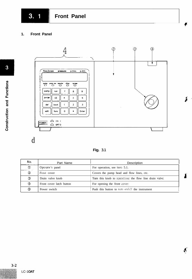
Opcrator's panel
Front cover
Drain valve knob
Front cover latch button
1. Front Panel
For operation, see itcm 5.1.
Covers the pump head and flow lines, ctc.
Turn this knob to open/closc the flow line drain valve.
For opening the front covcr.
flow/press pressure p m a x pmin 711
4 4
1
ON I
OFF0 POWER-
I f \ I
d Fig. 3.1
Part Name I Description I
Power switch 1 Push this button to turn on/off the instrument I
3-2 LC-1 OAT

-1 Front Panel &
2. Inside the Front Cover
/ d d b b d d Fig. 3.2
I, this troy catches
3-3

Rear Panel r$' t
Part Name
Extcmal input/output terminal block
Earth tcriiminal
Power cord connector
Fuse holder
S0L.V connector
PUMP ON - PUMPOFF -
Description
Uscd to makc connection with extcnmal cquipment.
Used [or grounding the instrument
Uscd to connect a power cord.
Two llises are in thc holder.
Uscd to comcct a solvcnt sclcctor valvc unit FCV-I OALIFCV- 1 I AL.
Fig. 3.3
No.
0
0
REMOTE connector Used to conncct with SCL-IOA or an additional LC-IOAT. SCC Scc- lion 4.9 "Installation of thc High Prcssure Gradient Elution Systcm."
.$
P
3-4 I ? LC-1 OAT
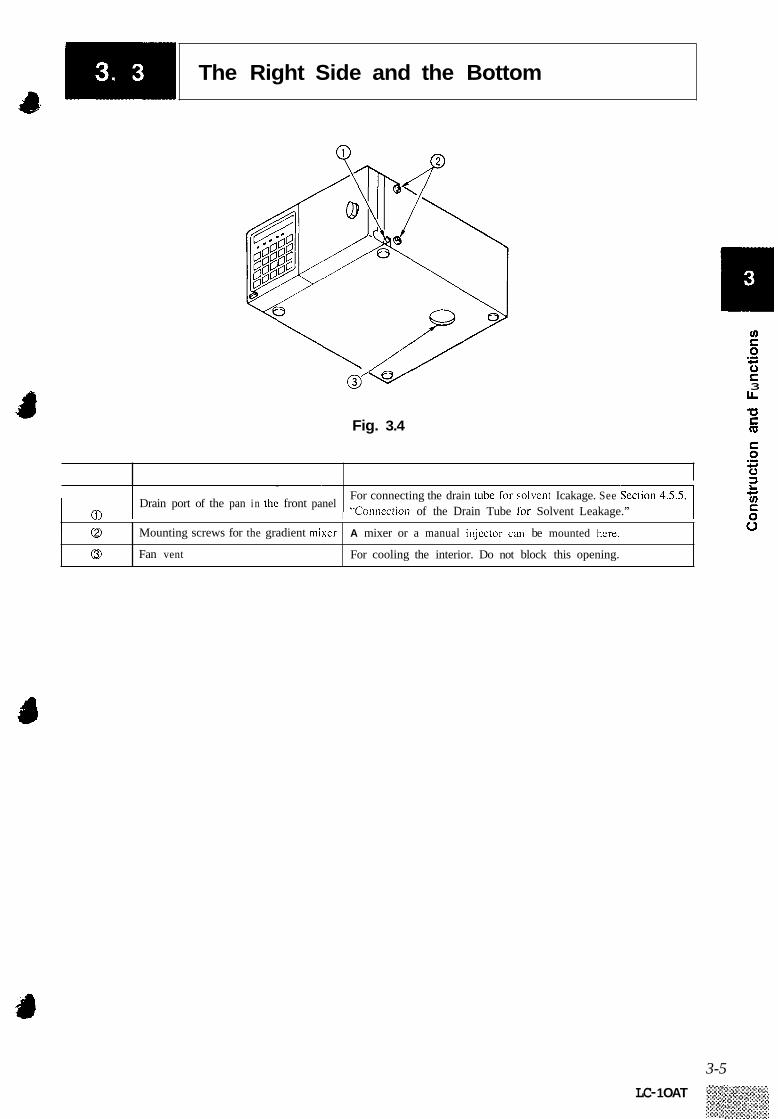
The Right Side and the Bottom
4s
Q 0
Fig. 3.4
Mounting screws for the gradient mixer
Fan vent
A mixer or a manual injector can be mounted here.
For cooling the interior. Do not block this opening.
_ _ _ _ ~ _ _ _ ~ ___ ____ ____ ____
For connecting the drain tube Tor solvcnt Icakage. See “Conneclion of the Drain Tube [or Solvent Leakage.” 1 @
1 Drain port of the pan in the front panel
3 L
3-5 LC- 1 OAT
Chapter 4 Installation
Contents
4.1
4.2
4.3
4.4
4.5
4.6
4.7
4.8
4.9
4.10
Conditions for Installation Site . . . . . . . . . . . . . . . . . . . . . . . . . . . . . . . . . . . . 4-2
Examples of System Configurations . . . . . . . . . . . . . . . . . . . . . . . . . . . . . . . . 4-3
Mounting of Multiple Units . . . . . . . . . . . . . . . . . . . . . . . . . . . . . . . . . . . . . . . 4-6 Electrical Connections . . . . . . . . . . . . . . . . . . . . . . . . . . . . . . . . . . . . . . . . . . . . 4-7
Tubing of the Unit . . . . . . . . . . . . . . . . . . . . . . . . . . . . . . . . . . . . . . . . . . . . . . 4-8 Connection of the Degasser . . . . . . . . . . . . . . . . . . . . . . . . . . . . . . . . . . . . . . .4-12
Mounting the Mixer . . . . . . . . . . . . . . . . . . . . . . . . . . . . . . . . . . . . . . . . . . . . . .4 - 16
Connection of the Injector, Column and Detector . . . . . . . . . . . . . . . . . . . .4-20
Installation of a High Pressure Gradient Elution System . . . . . . . . . . . . . . 4-23
Installation of a Low Pressure Gradient Elution System . . . . . . . . . . . . . . .4-26
4- 1

1.
2.
3.
4.
Conditions for Installation Site F
For correct and safe use of the instrument, proper care about the installation site should be taken.
Environmental Conditions To assure long service life and good performance of the instrument, avoid installation in a place exposed to corrosive gases or dust.
Precautions on Ventila- tion and Fire
Electromagnetic Noise
Installation Space Requirements
<<Cautions>>
5. Use in the Patient Environment
Provide adequate ventilation when using flammable or toxic solvents as mobile phase. Never use an open flame in the room particularly when flam- mable solvents are used.
Avoid installation in the vicinity of such equipment that generates a strong magnetic field. Use an additional noise filter if the power line has much noise.
r The LC- 1 OAT is designed to be used on a table or stand, preferably a solid and flat surface with a depth of 60cm or more. See Section 4.2 “Examples of System Configurations” for typical configurations of systems and installation spaces.
In selecting the installation site, due care should be taken with regard to the following items in order to assure the optimum per- formance of the instrument. ( 1 ) Ambient temperature should be within 5 to 35OC, and without
extreme fluctuations. Do not expose the instrument to the direct output from a heater or a cooler.
(2)
6 . (3) Do not expose the instrument to direct sunlight. 8 - (4) ( 5 )
The installation site should be vibration-free. Relative humidity should be within 45% to 85%.
LC-IOAT is not designed in consideration of the safety regulation for medical equipments. Therefore LC-IOAT can not be used in the patient environment.” * Patient environment: the area within a distance of 2.5m from
patients.
4-2 i
LC-1 OAT I I
Examples of System Configurations
1. Simple System
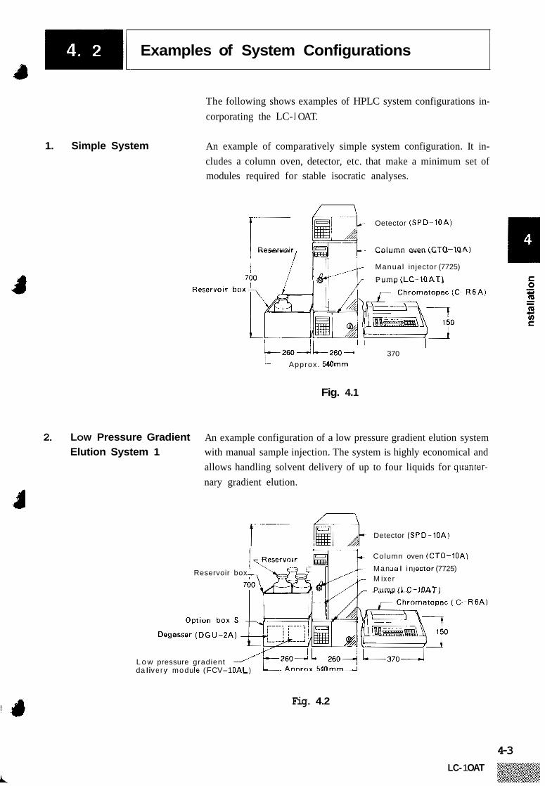
The following shows examples of HPLC system configurations in- corporating the LC- 1 OAT.
An example of comparatively simple system configuration. It in- cludes a column oven, detector, etc. that make a minimum set of modules required for stable isocratic analyses.
Oetector (SPD-1OA)
Reservoir Column oven (CTO-1OA)
Manual injector (7725)
Pump (LC-1OAT)
I
R 6 A )
370 Approx. 540mm
Fig. 4.1
2. LOW Pressure Gradient Elution System 1
An example configuration of a low pressure gradient elution system with manual sample injection. The system is highly economical and allows handling solvent delivery of up to four liquids for quanter- nary gradient elution.
Detector (SPD-1OA)
Column oven (CTO-1OA
Man ua I i n lector (7725) M i xer
Pump (LC-IOAT)
Reservoir box
Degasser (DGU-2A)
L o w pressure gradient da I i v e r y mod u I e ( F CV-1 OAL )
h )
-R6A)
Fig. 4.2
4-3 LC- 1 OAT

1 Examples of System Configurations
3. LOW Pressure Gradient Elution System 2
A low pressure gradient elution system including an automatic in- jector controlled by the SCL- 1 OA System Controller. Centralized control of each module is available through the use of the system controller allowing great ease of operation. The system can also readily be used for automatic analyses.
System control ler (SCL-1OA)
Detector (SPD-1OA)
Column oven (CTO-1OA) Automatic injector
Chromatopac (C-R7A) Degasser (DG U-1OA)
Syringe module
Fig. 4.3
4. High Pressure Gradient Elution System 1
An example configuration of a high pressure gradient elution system with manual sample injection. The LC- lOAT high pressure gradient elution system allows highly accurate gradient analysis with a small time lag.
~ ~ Detector (SPD-1OA)
,,- Column oven (CTO-1OA) Reservoir box -I ~~,
,~~ Manual sample injector (7725)
Chromatopac (C-R5A)
Degasser (DG U -4A)
Pump (LC-lOAT).,
L~ Pump (LC-1OAT)
&-
Fig. 4.4
4-4
1 I Examples of System Configurations
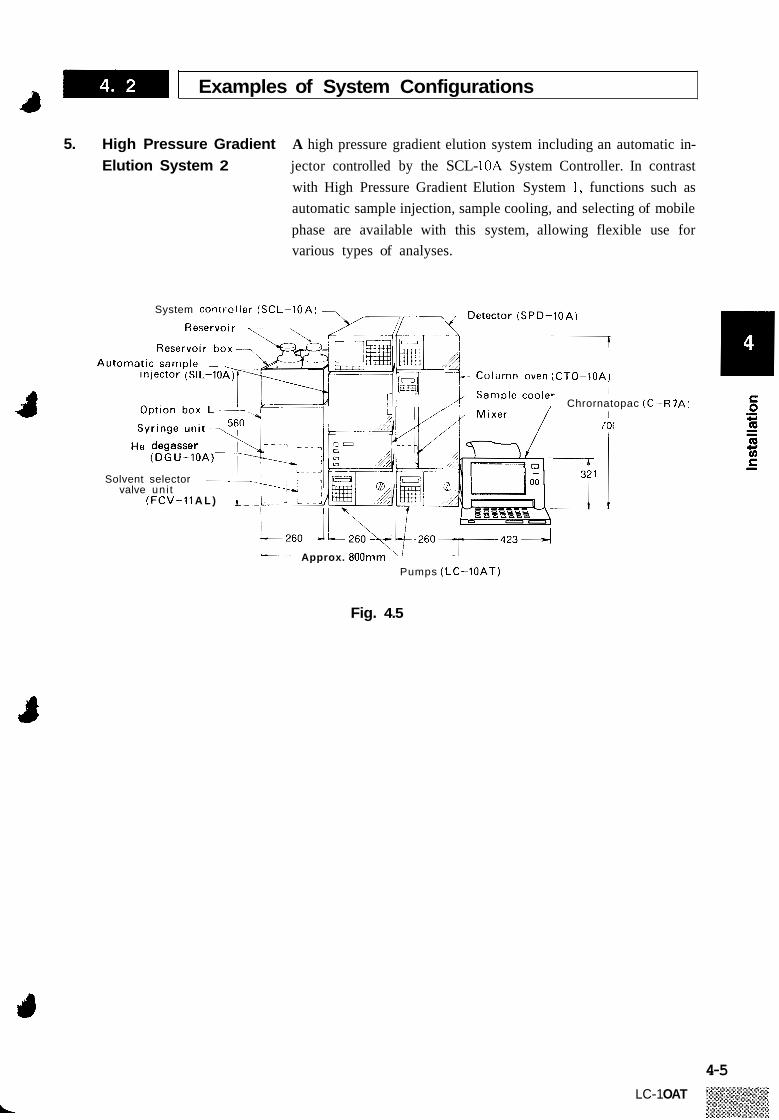
5. High Pressure Gradient Elution System 2
A high pressure gradient elution system including an automatic in- jector controlled by the SCL- 10A System Controller. In contrast with High Pressure Gradient Elution System 1, functions such as automatic sample injection, sample cooling, and selecting of mobile phase are available with this system, allowing flexible use for various types of analyses.
System cont ic l ler (SCL-1OA)
Chrornatopac ( C -
Solvent selector valve uni t
(FCV-11 A L )
Approx. 800rnm Pumps (LC-1OAT)
-R7A)
Fig. 4.5
4-5 LC-1 OAT

S 0
Mounting of Multiple Units
The LC- 1 OAT may be stacked one on another for use. The SPD- 1 OA detector, CTO-I OA column oven, SIL-1OA automatic injector, etc. may also be stacked on an LC-IOAT. When stacking the units, it is possible to fix units together to prevent them from falling over during an earthquake or the like. The units should be fixed using the accessory tie plate.
(1 ) Unscrew the screws that are used to fixed the unit cases. (2) Use the same screws to fix the tie plate.
4-6
Fig. 4.6
L
Electrical Connections
4 Before connecting the power source, confirm that the following con- ditions are met:
-%Itage and capacity of the power outlet Part number 228-3 1900-9 1, 92
90 - 130V- 1 OOVA 50/60Hz Part number 228-3 1900-93
200 - 250V- 1 OOVA 50/60Hz The instrument will not exhibit satisfactory performance if operated on unstable line voltage or insufficient power capacity. In addition, the power capacity required from the overall system should be con- sidered when preparing the power source. 0 Make sure that the power switch on the main unit is turned
off.
1. Connection to the power outlet
Plug in the female end of the accessory power cord to the power connection on the back of the unit. Connect the male end to the power outlet.
<<Caution>> (1) The LC-IOA employs a three-pronged power cord including a grounding wire. Be sure to connect the power cord to a three-pronged power outlet including a protective conductor terminal so as to ensure proper grounding. For prevention of electric shock and to ensure stable opera- tion, be sure to ground the instrument.
(2)
4-7 LC-1 OAT

S
Piping of the Unit
1. Preparation of Reservoir Prepare a reservoir of a capacity of 500ml or more.
2. Removing the Front Before connecting the flow lines of the unit, remove the front cover.
(2) The cover may be removed by pulling it while pressing the side of the cover as shown in the illustration below.
Cover (1) Press the latch button to open the cover.
Ti
Pump inlet (Bushing installed for transportation)
Fig. 4.7
3. Connection of the Suction Filter hand.
(1) Unscrew the transportation bushing dosing the pump inlet by
Replace this bushing when the unit is not to be used for a long period of time in order to prevent the entrance of dust into the flow line. Remove the 3D bushing from the suction filter tube. Cut the tube to an appropriate length according to the distance between the reservoir and the pump inlet. Put the filter in the reservoir as shown in the following il- lustration and run the tubing through the lid with four holes followed by the cap. Replace the 3D bushing back on the tube. Connect the 3D bushing of the suction filter line to the pump inlet. Fix the tube using the tubing clip as shown in the next il- lustration.
(2) ( 3 )
4F C' ( 1
(4)
( 5 )
(6)
4-8 LC-1 OAT
L

-1 Piping of the Unit a 30 Bushing,
Suction f i l t e r
1 <<Cautions>>
4. Connection of the Drain ( I ) Tube (2)
(3)
(4)
1 &-- Remove the bushing
Filter element
/
-/ Suction filter
element
Screw the bushing Reservoir into the pump inlet
Tubing c l ip
Fig. 4.8
Keep the filter element clean to prevent clogging. For constantly stable analysis, the mobile phase in the reser- voir should be degassed. See Section 4.6 “Connection of the Degasser.”
Remove the transportation cap mounted in the drain port. Screw the 1.6MN bushing (PEEK) of the accessory drain tub- ing into the drain port. Prepare a waste container and put the other end of the drain tube in it. Fix the drain tube using the tubing clip as shown in the next illustration.
4-9

-1 Piping of the Unit P
5. Connection of the Drain Tube for Solvent Leakage
<<Caution>>
Drain tube A .-/ ‘yubing clip
Put the waste container on the floor or the like so that it i s placed lower than the drain port
pi
Fig. 4.9
If liquid leaks in the unit, it accumulates in the pan on the front panel. Connect the drain tube for solvent leakage to lead the solvent to a waste container. (1) Fit the L-shaped drain tube to the drain port for solvent
leakage at the right side of the unit. (2) Connect the drain tube for solvent leakage and the L-shaped
drain tube using the straight joint. ( 3 ) Put the other end of the drain tube for solvent leakage in
a waste container.
If the flow line of the drain tube for solvent leakage is located above the drain port for solvent leakage, the leaked solvent will not be discharged. Be sure to put the waste container lower than the unit, and direct the drain tube downward. Pour some water in the pan to check that waste will not back up but flow freely to the waste container,
I \ Fit the Straight tube joint \ @
Waste container
Fig. 4.10
4-10
A

-1 Piping of the Unit
6. Tubing for Solvent Each component of the LC-IOA series has a drain port for solvent leakage at the front right side of the unit, which discharges liquid if leakage occurs in the unit. Tubing for solvent leakage should be conducted when installing the system. (1) Fit the accessory L-shaped drain tube to the drain port for
solvent leakage on each component. (2) Connect the L-shaped drain tube fitted on the lowest com-
ponent with a drain tube using a straight joint, and lead it to a waste container. For the next higher component, use a T joint to connect on L-shaped drain tube and the tubing from upper component, and lead the other to the waste container. For the third and higher components, make interconnection with the other com- ponents using a T joint and a drain tube cut in an appropriate length. Be sure to incline the L-shaped drain tubes downward and f ix them on the sides of the units using the accessory pipe clips, if necessary. Place the waste container lower than the lowest unit.
Leakage in the LC-1OA System
(3)
T-shaped joint
drain tubes. for solvent leakage
/ Drain port for solvent leakage
Fig. 4.11
4-1 I

Connection of the Degasser iF
Degassing of mobile phase is required for constantly stable analysis for the following reasons. ( 1 ) It prevents troubles that would occur from generation of bub-
bles. (2) It prevents unstable measurements that would occur due to
variations in the concentration of dissolved gases. Helium degassing and vacuum degassing through a resin membrane are popular in HPLC. Choose from these according to your needs. See Section 11.3 “Optional Units List.” As examples, the connection of DGU-2A and DGU-3A to LC- 1 OAT will be described in this chapter. The former is for helium degassing, and the latter is for vacuum degassing using a resin membrane.
Connection of the DGU-2A Use helium gas of high purity (99.995% or higher) for degassing. (helium degassing) Set a pressure regulator (optional) to the helium gas cylinder
and connect the pressure regulator and the DGU-2A with a carrier gas pipe (optional). For the reservoir, prepare a type LSI glass container. (A com- monly used glass reagent container of a capacity of 500 or 1000ml).
F . 1.
(1)
(2)
<<Caution>>
Helium gas cylinder u
Helium gas cylinder
Hel ium gas inlet
Fig. 4.12
Never use a container with a crack or other flaw for a reservoir.
4-12 LC-1 OAT

-1 Connection of the Degasser 9
Category
0
(3) Assemble the reservoir cap as shown in the illustration.
Part Name
Lid
TO DGU-PA &
@ ::: 0
To the pump inlet
Teflon tubing
Teflon tubing
::: 8 0
Q I Bottle cap
Filter elemen1 of the suction filter
Helium gas bubbler frit
7 Teflon packing
Teflon tubing
Teflon tubing
Fig. 4.13
~~
Description
Outer lid of the reservoir (B3) ~
Inner lid of the reservoir
Packing for the inncr lid
3.0 x 2.0 x 230
3.0 x 2.0, Connect to the pump inlet.
Uscd to tilter the mobile phase.
Helium gas bubbler frit
3 x 2 x 600 To be connected to an “OUT” (A, B, C, D) port of the DGU-2A.
3 x 2 x 600 To be connected to an “IN” (A, B, C, D) port of the DGU-2A.
::: Parts @ and @ above are accessories supplied with the LC-IOAT. Parts with other numbers are accessorics supplied with thc DCU-2A.
4-13 LC-1 OAT

S 0
4-14
I) Connection of the Degasser F
(4) Put the mobile phase in the reservoir. Also put the filter ele- ment assembled in (3) into the reservoir, then firmly close the cap.
TO DGU-2A
To the pump inlet
Fig. 4.14
Remove the caps set to DGU-2A ports to which you will make connection. Connect Teflon tubing led from the reser- voir to OUT (A, B, C, or D) and IN (A, B, C, and D) ports of the DGU-2A, as shown in the illustration. Keep the unused ports covered with the caps. Save the removed caps to use again to protect the degasser from entry of dust into flow lines when it is not to be used for a long time. T ' 4
4 Helium gas to reservoir
Fig. 4.15
LC-1 OAT

-[ Connection of the Degasser 9 1
2. Ventilation of Helium Gas (1)
(2)
Prepare a glass container. Fill it with a solvent that is miscible with the mobile phase. Connect one end of the accessory Teflon tubing to the VENT port of the DGU-2A. Put the other end in the container and loosely cap the container with aluminum foil. Place the container near a fume hood, ventilating fan or win- dow so as to release the gas from the DGU-2A to outside the room.
(3)
3
d
Fig. 4.16
3. Plumbing of the DGU-3A (1) Carry out plumbing from the reservoir to the DGU-3A and from the DGU-3A to the LC- lOAT as shown in the illustration below. First, remove the caps set to DGU-3A ports which you want to use. Keep unused ports covered with caps. Save the removed caps to use again to protect the degasser from entry of dust into flow lines when it is not to be used for a long period.
D G U- 3 A 7
L o 1 O J - Use 3D bushings that, are accessories supplied with the DGU-3A
3 0 bushings that are accessories for the suction f i l t e r may
Suction filters
I 1.
- Connect these
-
Use 3D bushings that are supplied wi th the DGU-3A
Fig. 4.17
4-15
LC- 1 OAT

m m Mounting the Mixer
For gradient elution using the LC-IOAT, a special mixer (P/N 228- 28000-91, optional) that is excellent in mixing solvents is available. Follow the instructions below for mounting the mixer and selecting mixer capacity.
1. Mounting Position The mixer may be mounted in any of the following positions.
(1) (2) (3)
The right side panel of the LC-IOAT The inside left of the CTO-IOA The inside right of the CTO-1OA
The following three capacities can be selected. Select the right mixer capacity according to the analysis requirements. (1) 2.6ml (2) 1.7ml (3) 0.5ml
3. Selecting Mixer Capacity Mixer capacity can be changed by altering the plumbing. When it is shipped, it is set to 2.6ml. To change the setting, follow the instructions below: (1) Remove the mixer cover.
Screw
Screw
Screw
Fig. 4.18
Screw
Cover
Ec;,
4-16 LC-1 OAT

-1 Mounting the Mixer 4
(2) According to the desired capacity, change the plumbing as shown in the following illustration:
(A) Plumbing for 0.5ml (B) Plumbing for 1.7ml (C) Plumbing for 2.6ml (Factory default)
To the injector
o the injector
\
Remove tubing and cover the por t w i th caps fo r prevention
To the injector
o the injector
\
Remove tubing and cover the por t w i th caps fo r prevention of dust. U
To the injector
Fig. 4.19
4. Mounting the Mixer on the LC-1OAT
( I ) Move the pre-mixer section forward and fasten it by screws as shown in the following illustration:
Pre-mixer posit ion when shipped - Move i t t o the left
Unscrew the screws R efesten the w @ w s
Fig. 4.20
4-17

-1 Mounting the Mixer
(2) Unscrew the screws on the right side of the pump, and fix the mixer with the screws as shown below:
Unscrew .*
the screws Refasten the
screws
Fig. 4.21
(3) Carry out piping between the mixer and injector referring to Section 4.9 “Installation of the High Pressure Gradient Elu- tion System.”
I
(4) Remount the mixer cover.
Screw
4-18
The pre-mixer joint sticks out of the cover.
Fig. 4.22
L
. -1 Mounting the Mixer
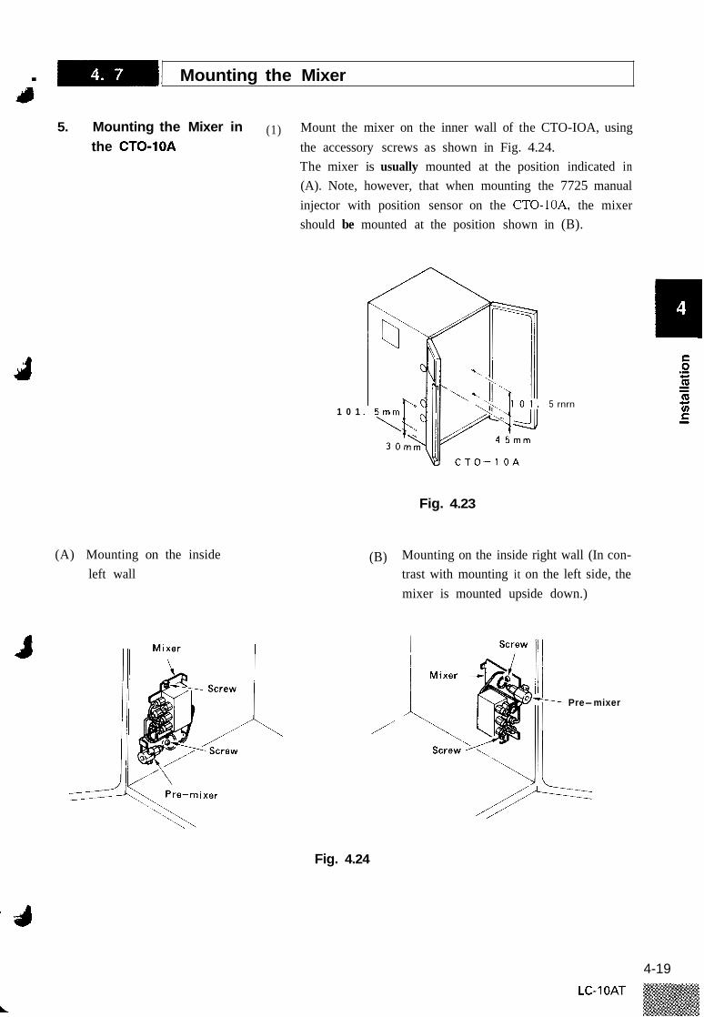
5. Mounting the Mixer in (1) Mount the mixer on the inner wall of the CTO-IOA, using the accessory screws as shown in Fig. 4.24. The mixer is usually mounted at the position indicated in (A). Note, however, that when mounting the 7725 manual injector with position sensor on the CTO-IOA, the mixer should be mounted at the position shown in (B).
the CTO-1OA
1 0 1
Fig. 4.23
I
(A) Mounting on the inside left wall
5 rnrn
(B) Mounting on the inside right wall (In con- trast with mounting it on the left side, the mixer is mounted upside down.)
Pre-mixer
/
Fig. 4.24
4-19
Connection of the Injector, Column and Detector
F
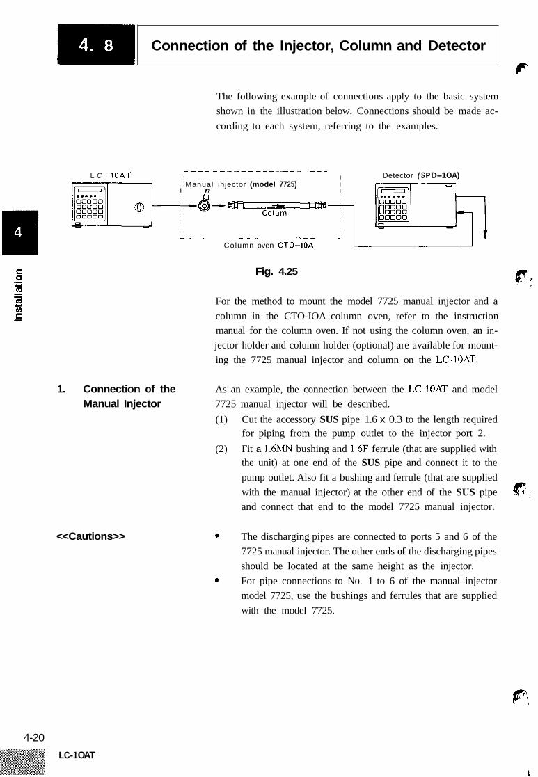
The following example of connections apply to the basic system shown in the illustration below. Connections should be made ac- cording to each system, referring to the examples.
1.
L C -10AT Detector ( S P D-1 OA) - - - - - - - - - - - - - - - - - - - - - -
I I I Manual injector (model 7725) I v
I n I
L J
Column oven CTO-1OA
Fig. 4.25
For the method to mount the model 7725 manual injector and a column in the CTO-IOA column oven, refer to the instruction manual for the column oven. If not using the column oven, an in- jector holder and column holder (optional) are available for mount- ing the 7725 manual injector and column on the LC-IOAT.
Connection of the Manual Injector
As an example, the connection between the LC-]OAT and model 7725 manual injector will be described. (1) Cut the accessory SUS pipe 1.6 x 0.3 to the length required
for piping from the pump outlet to the injector port 2. (2) Fit a 1.6MN bushing and 1.6F ferrule (that are supplied with
the unit) at one end of the SUS pipe and connect it to the pump outlet. Also fit a bushing and ferrule (that are supplied with the manual injector) at the other end of the SUS pipe and connect that end to the model 7725 manual injector.
<<Cautions>> 0 The discharging pipes are connected to ports 5 and 6 of the 7725 manual injector. The other ends of the discharging pipes should be located at the same height as the injector. For pipe connections to No. 1 to 6 of the manual injector model 7725, use the bushings and ferrules that are supplied with the model 7725.
0
4-20
LC-1 OAT
i

-1 Connection of the Injector, Column and Detector d d
Cut the plpe to an appropriate length and connect it to por t 2 w i th a bushing and a ferrule
sus PIPe
rear view nual injector, model 7725
injector holder
Fig. 4.26
3 2. Connection between the The following is an example of a typical connection between the Injector and Column manual injector model 7725 and column.
(1) Cut the accessory SUS pipe 1.6 x 0.3 to the length required for tubing from the injector to the column. Fit bushings and ferrules at both ends of the SUS pipe. Connect these ends of SUS pipe to the injector and column.
(2) (3)
<<Cautions>>
/j
0 In order to minimize sample broadening, make the tubing between the injector and column as short as possible. In order to eliminate dead volumes from the flow line, cut the pipe in such a manner that the cut face is perpendicular to the pipe axis.
0
Cut the pipe perpendicular Cy l i ndrica I section to the ax is
Bushing.1 .6 M N Ferrule.l.6F
C T O - 1 O A , r - --- - ---- -
To the detector
Manual injector rear view
Fig. 4.27
1 4-2 1
LC- 1 OAT

-1 Connection of the Injector, Column and Detector ‘ c
3. Connection between As an example, the connection between column and the SPD-1OA
(1) Cut the ETFE tube (1.6 x 0.3) that is supplied with the SPD- 10A to the length required to make connection from the column outlet to the cell inlet of the SPD-IOA. Fit bushings (I .6MN PEEK) at both ends of the ETFE tube. Connect the ends of the ETFE tube to the column outlet and cell inlet (with a blue mark) of the detector as shown in the following illustration. See cautions for “Section 4.8.2 Connection between the In- jector and Column.”
Column and Detector detector will be described.
(2) (3)
Blue marking band Coupling / Column
Pipe f rom the cel l inlet of SPD-1OA
Bushing.1.6MN PEEK ETFE tube (Fasten by hand.) From the manual
i n j ecto r
Fig. 4.28
4-22
LC-1 OAT
1. Wiring for a System Controlled by the SCL-1 OA
J
I
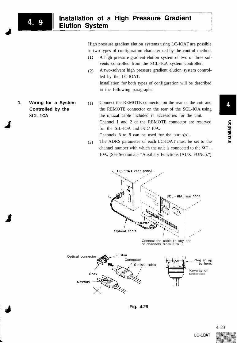
High pressure gradient elution systems using LC-IOAT are possible in two types of configuration characterized by the control method. ( I ) A high pressure gradient elution system of two or three sol-
vents controlled from the SCL-I OA system controller. A two-solvent high pressure gradient elution system control- led by the LC-IOAT. Installation for both types of configuration will be described in the following paragraphs.
(2)
(1) Connect the REMOTE connector on the rear of the unit and the REMOTE connector on the rear of the SCL-IOA using the opticaI cable included in accessories for the unit. Channel 1 and 2 of the REMOTE connector are reserved for the SIL-IOA and FRC-IOA. Channels 3 to 8 can be used for the pump(s). The ADRS parameter of each LC-IOAT must be set to the channel number with which the unit is connected to the SCL- 10A. (See Section 5.5 “Auxiliary Functions (AUX. FUNC).”)
(2)
L-10A rear Panel
/ /
/’ Connect the cable to any one of channels f rom 3 to 8.
Optical connector Connector -Plug i n up
to here.
Keyway on underside
Fig. 4.29
4-23 LC-1 OAT

Installation of a High Pressure Gradient Elution System CF
lli 2. Wiring for a System (1) Connect two LC-10ATs by the REMOTE connectors on the
Controlled by the LC-1 OAT
rear panels, using the accessory optical cable.
\, The LC-1OAT rear panel
/’ \
Optical cable --
Fig. 4.30
(2) Set 85 to the ADRS parameter of each LC-IOAT. (See Section 5.5 “Auxiliary Functions (AUX.FUNC).”)
3. Piping of the High As an example, piping for a high pressure binary gradient elution system with two LC-IOATs, a degasser and a mixer will be Pressure Gradient
Elution System described.
IN OUT 0 2 0 i * T o injector
- Mobile phases
L C - 1 O A T
Fig. 4.31
Carry out piping referring to the - Aowing connect.m method.
(1) Prepare a reservoir. Degassing of mobile phases is necessary for stable gradient elution of good reproducibility. Carry out piping up to the pump inlet referring to Section 4.6 “Con- necting the Degasser.”
PI
4-24 LC-1 OAT
a -1 Installation of a High Pressure Gradient Elution System
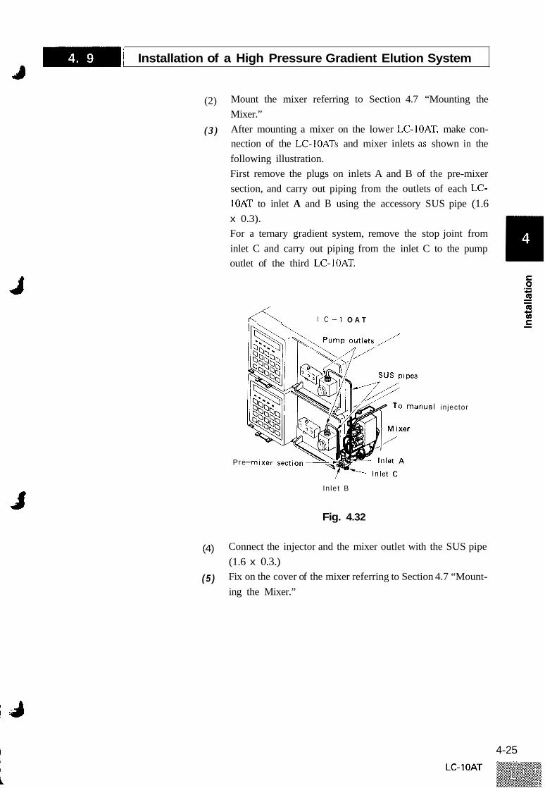
(2) Mount the mixer referring to Section 4.7 “Mounting the Mixer.” After mounting a mixer on the lower LC-IOAT, make con- nection of the LC-IOATs and mixer inlets as shown in the following illustration. First remove the plugs on inlets A and B of the pre-mixer section, and carry out piping from the outlets of each LC- ]OAT to inlet A and B using the accessory SUS pipe (1.6 x 0.3). For a ternary gradient system, remove the stop joint from inlet C and carry out piping from the inlet C to the pump outlet of the third LC-IOAT.
( 3 )
A L C - 1 O A T
P r e
In le t B
Fig. 4.32
in jector
(4) Connect the injector and the mixer outlet with the SUS pipe (1.6 x 0.3.) Fix on the cover of the mixer referring to Section 4.7 “Mount- ing the Mixer.”
( 5 )
4-25

Installation of a Low Pressure Gradient Elution System
F
This pump allows configuration of low pressure gradient elution systems that can handle up to four liquids, using the FCV-IOAL low pressure value module. The installation of the system is described in the following paragraphs.
1. Configuration of pressure gradient elution system
FCV-1 OAL S 0
The simplest low pressure gradient elution system consists of the units and parts listed below: @ LC-IOAT 1 ea. @ Mixer 1 ea.
0 FCV-IOAL Low pressure value module 1 ea.
(1) Make sure that the power switch of the module is turned Off .
Using the cable included in the accessories for the FCV- IOAL, connect the FCV-IOAL and the S0L.V connector on the rear of the pump module. Fasten the fixing screws on the connector of the module with a screw driver. The FCV-IOAL end of the cable has a flat cable connector; As such, fixing by screws is not done for the FCV-1OAL connector.
(2)
(3 )
LC-1OAT rear panel
Screws
Accessory cable FCV-1OAL rear Panel
Fig. 4.33
<<Cautions>> 0 In order to reduce dead volume in the flow line and allow a minimum time lag for gradient elution, install the FCV- lOAL as close to the LC-IOAT as possible.
3. Piping of the Low Pressure Gradient Elution System
Carry out piping referring to the following connecting method.
(1) Prepare reservoir containers. Because degassing of the mobile phases is needed, carry out piping to the inlet joints of the FCV- 1 OAL referring to Section 4.6 “Connecting the Degasser.”
4-26 LC-1 OAT

-1 Installation of a Low Pressure Gradient Elution System 1 *)
(2) Connect the outlet of the 5-way branching block and the pump inlet of the module with the accessory tube (40cm length). The FCV-IOAL has four inlet ports (from A to D). If not every port is used, disconnect the pipe corresponding to the unused flow line from that inlet of the 5-way branching block. Then, be sure to fit the unused inlet with a plug (included in the accessories for the FCV- 1 OAL).
J
F C V - 1 O A L
5-way branching block
Suction f i l ter * F i t plug t o unused inlet
Fig. 4.34
(3) Remove the normal drain value line filter with the supplied wrench. Mount the low pressure line filter included with the FCV- 1 OAL.
L ine f i l ter
Gasket 1 @ 9 Remove
D r a i n valve knob @ - Line f i l ter
Instal l
Fig. 4.35
4-27

-1 Installation of a Low Pressure Gradient Elution System I ~
(4) Install the mixer, referring to the instruction in 4.7 “Mounting the mixer”. Connect the LC-IOAT and the inlet of the mixer as shown in the figure below. Remove the plugs of inlets A and B of the pre-mixer, and con- nect the pump outlet of the LC-IOAT with inlet B by using the 1.6 x 0.3 SUS pipe provided with the mixer. Cover inlet A with the stop joint included with the mixer.
( 5 )
L C - 1 O A T
Pump outlet
/ I / SUS pipes
o manual injector
Pre-mixer se
I
Inlet B
Fig. 4.36
(6) Connect the injector and the mixer outlet with the 1.6 x 0.3 SUS pipe. Mount the cover, referring to the instruction in 4.7 “Mounting (7) the mixer”. fR ,
4-28 LC-1 OAT

Chapter 5 Operation
Contents
5.1 Basic Operation . . . . . . . . . . . . . . . . . . . . . . . . . . . . . . . . . . . . . . . . . . . . . . . . . 5-2
5.2 Constant Flow Solvent Delivery . . . . . . . . . . . . . . . . . . . . . . . . . . . . . . . . . . . 5-8
5.3 Constant Pressure Solvent Delivery.. . . . . . . . . . . . . . . . . . . . . . . . . . . . . . . . 5-11
5.4 Creation of Time Programs and Execution . . . . . . . . . . . . . . . . . . . . . . . . . . 5-12
5.5 Auxiliary Functions (AUX.FUNC) . . . . . . . . . . . . . . . . . . . . . . . . . . . . . . . . . .5-20
5.6 High Pressure Gradient Elution Mode . . . . . . . . . . . . . . . . . . . . . . . . . . . . . . 5-29
5.7 Low Pressure Gradient Elution Mode . . . . . . . . . . . . . . . . . . . . . . . . . . . . . .5-32
5.8 Plunger Washing Method . . . . . . . . . . . . . . . . . . . . . . . . . . . . . . . . . . . . . . . . .5-33
5.9 Change of Mobile Phase . . . . . . . . . . . . . . . . . . . . . . . . . . . . . . . . . . . . . . . . .5-35
11 E
0 .- c,
f 8
5-1

IBI-
1. Start-up
Basic Operation
<<Caution>>
The operation of the unit is performed through the keys on the operator’s panel. The status of operation may be checked on the display at any time. When using the SCL-IOA for control, see Sec- tion 7.2 “Control from the SCL-IOA.”
(1) Press the power switch located at the lower left of the front panel to tiiim on the unit. The unit is turned off by repressing the switch.
Power switch in OFF state Power switch in ON state
Fig. 5.1
(2) When the power is switched on, a memory check is carried out automatically. If there is nothing irregular in the memory, the ROM version number is displayed for several seconds and then the display shown in the following illustration will appear to enable operation. (Values displayed vary according to setting.) This is the initial state. F.
f flow/Dress Dressure D.max ~ . m i n I , . .
\ l l / / Ir0.000 0 100 01 k / I I \ \ I
pump prog run remote cflor cprsos o o o m o
Fig. 5.2
If an error message is displayed after tui-ning on the unit, see Section 9.2 “Error Messages” for appropriate measures.
5-2 LC-1 OAT

-1 Basic Operation 4
0
@
2. Description of the Display The display has a screen and LED lamps. The function of each part is as follows:
Indicates the set flow rate (mNmin) when the module is in the constant flow solvent delivery mode, or the set pressure value (X
10’ Pa) in the constant pressure solvent delivery mode.
The pressure value measured by the pressure sensor (X 10’ Pa)
flow/press
pressure
Q
p.max
u.min
Q 9 Q
Indicates the set upper limit pressure (x lo5 Pa)
Indicates the set lower limit pressure (X lo5 Pa)
pump prop ranots cnow cpmu
Pump
program
Fig. 5.3
Pump operation indicator lamp The lamp is lit when the pump is in operation.
Programmed operation indicator lamp The lamp is lit when a program is running.
~~
Indication or Name Function
remote REMOTE mode indicator lamp Flashes when the pump is controlled by the SCL-10A.
c.flow Constant flow mode indication lamp The lamp is lit when the module is in the constant flow solvent delivery mode.
c.press Constant pressure mode indication lamp The lamp is lit when the module is in the constant pressure solvent delivery mode.
~~
Note. lo5 Pa = 1 bar = Ikgf/cm2
Y n v
5-3 LC- 1 OAT
-1 Basic Operation I I n
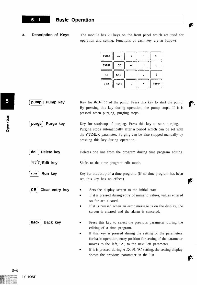
3. Description of Keys
pump Pump key 1 3 = C 0 .-
4-
!! [E) Purge key
0 a Q
Delete key
(edit) Edit key
Run key J
Clear entry key
(m] Back key
The module has 20 keys on the front panel which are used for operation and setting. Functions of each key are as follows.
Key for stadstop of the pump. Press this key to start the pump. By pressing this key during operation, the pump stops. If it is pressed when purging, purging stops.
(p'.
Key for stadstop of purging. Press this key to start purging. Purging stops automatically after a period which can be set with the P.TIMER parameter. Purging can be also stopped manually by pressing this key during operation.
Deletes one line from the program during time program editing.
Shifts to the time program edit mode.
Key for stadstop of a time program. (If no time program has been set, this key has no effect.) F:
Sets the display screen to the initial state. If it is pressed during entry of numeric values, values entered so far are cleared. If it is pressed when an error message is on the display, the screen is cleared and the alarm is canceled.
Press this key to select the previous parameter during the editing of a time program. If this key is pressed during the setting of the parameters for basic operation, entry position for setting of the parameter
If it is pressed during AUX.FUNC setting, the setting display moves to the left, i.e., to the next left parameter.
shows the previous parameter in the list.
I
p ,
5-4 LC-1 OAT
-1 Basic Operation 4
tlow
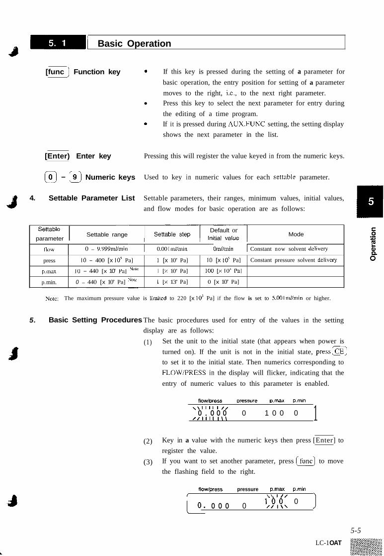
[func Function key 0 If this key is pressed during the setting of a parameter for basic operation, the entry position for setting of a parameter moves to the right, i.e., to the next right parameter. Press this key to select the next parameter for entry during the editing of a time program. If it is pressed during AUX.FUNC setting, the setting display shows the next parameter in the list.
0
0 - 9.999ni//min 0.00 I m//min Omllrnin I Constant now solvent deliveiy
[Enter) Enter key Pressing this will register the value keyed in from the numeric keys.
press
p.max
p. min.
@ - @ Numeric keys Used to key in numeric values for each settable parameter.
10 - 400 [x 10’ Pa]
10 - 440 [x 10’ PJ] Note
0 - 440 [x 10’ Pa]
1 [x 10’ Pa]
I [x 10’ Pa]
1 [x 13’ Pa]
10 [x 10’ Pa]
100 [x 10’ Pal
0 [x 10’ Pa]
Constant pressure solvent dclivery
4. Settable Parameter List Settable parameters, their ranges, minimum values, initial values, 19 and flow modes for basic operation are as follows:
I
Default or Settable range
parameter Settable I Mode
~~
Note: The maximum pressure value is limitcd to 220 [x 10’ Pa] if the flow is set to 5.001mllmin or higher.
5. Basic Setting Procedures The basic procedures used for entry of the values in the setting
Set the unit to the initial state (that appears when power is turned on). If the unit is not in the initial state, p r e s s m to set it to the initial state. Then numerics corresponding to FLOW/PRESS in the display will flicker, indicating that the entry of numeric values to this parameter is enabled.
display are as follows:
(1)
flow/Dress Dressure Dmax D.rnin \ \ I I I I I / / 0 . 0 0 0 0 1 0 0 0
/ / I 1 1 1 I \ \ 1 (2) Key in a value with the numeric keys then press [Enter] to
register the value. If you want to set another parameter, press Ifunc) to move the flashing field to the right.
(3)
flow/press pressure pmax pmin I \ \ I / I \
1 - 0 - 0 - 0 L o . 0 0 0 0 / / I \ \ J 5-5
LC-1 OAT

-1 Basic Operation ‘ F
(4) To cancel a value just keyed in, press before pressing m.
( 5 ) To return the display to the initial state after setting, press
6. Setting of the Maximum To protect columns and other components in the flow line, set an Pressure Value upper pressure limit. If the pressure value measured by the pressure
sensor exceeds the upper pressure limit, the limiter will be activated to stop solvent delivery automatically. When the limiter is activated, an alarm beeps and the following message w ill be displayed.
r 1 fp. flow/press pressure p.rnax pmin
E R R O R P - M A X
<<Setting Example>>
7.
The setting procedures are as follows:
Example: To set p.max (upper pressure limit) to 150 [X lo5 Pa]: (1) Press @ to enable the entry of p.max (the entry field
flashes).
flow/press pressure p.max p.min f \ \ I / / 7
1 - 0 0 0 / / I \ \
0.000 0 1
(2) Press 0 , @ , @ , and [G). The following display appears, and the setting is complete.
flow/press pressure p.rnax p.min \ \ I I /
/ / I \ \ 1 5 0 0 0 . 0 0 0 0
Setting the Lower Limit Pressure
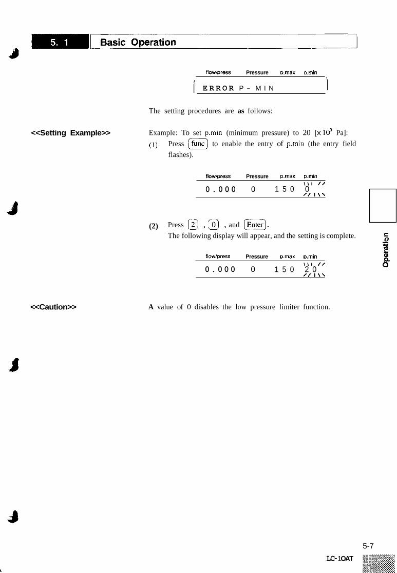
To prevent drawing air into the flow line when the mobile phase in a reservoir has been exhausted, or for safety measures in the case solvent is leaking from the flow line, a lower pressure limit should be set. The limiter will be activated if the pressure is still lower than the minimum pressure even one minute after starting solvent delivery. When the limiter is activated, the alarm beeps, the solvent delivery stops automatically and the following message will be displayed.
5-6 LC-1 OAT
flow/Dress Pressure nmax mmin
<<Caution>>
<<Setting Example>>
1 E R R O R P - M I N 1 The setting procedures are as follows:
Example: To set p.min (minimum pressure) to 20 [x lo5 Pa]:
(1) Press (fu..1 to enable the entry of p.min (the entry field flashes).
flow/aess Pressure mmax nmin \ \ I / /
/ / I \ \ 1 5 0 0 0 . 0 0 0 0
(2) Press 0 , @ , and [ G I . S 0 m
The following display will appear, and the setting is complete. .- 4-
flow/Press Pressure mmax mmin \ \ I / /
/ / I \ \ 1 5 0 2 0 0 . 0 0 0 0
A value of 0 disables the low pressure limiter function.
5-7 LC- 1 OAT

Constant Flow Solvent Delivery ~
1. An Operation Example of The following is an example of operation for constant flow solvent Constant Flow Solvent delivery: Delivery (1) Prepare a mobile phase and pour it into a reservoir followed
by the suction filter. Carryout piping of flow line referring to Section 4.8 “Con- nection of the Injector, Column and Detector.” Turn the drain valve knob counterclockwise by 180” to open the drain valve. Make sure that the drain tube is put into a waste container.
(2)
(3 )
<<Note>>
1 8 0 ‘
m
Drain valve knob
Fig. 5.4
(4) Press the power switch. ( 5 ) Check that the pressure value indicated on the display is in
the range from -3 to 3 [x lo5 Pa]. If not, carry out zero adjustment for the pressure sensor. (See Section 5.5 “AUX.FUNC Functions .”) Check that the upper pressure limiter and lower pressure limiter are appropriate. (See Section 5.1 “Basic Operation.”) Press (E) , then the pump will operate with a flow rate of about 9.9mllmin.
(6)
(7)
In normal operation, solvent delivery at the preset flow rate starts immediately after the [pu’np) or (z) key is pressed. In the two cases (a. and b.) below, however, solvent is delivered at a low rate for a few seconds until the home position of the pump is detected. After the home position is detected, the solvent delivery rate increases to the preset value. a. The [G) or (purge) key is pressed for the first time
after power-on. The Ipump) or (G] key is pressed for the first time after the high pressure limiter is activated with a limit value of 220 [x lo5 Pa] or higher.
b.
(8) Observe the condition of solvent discharged from the drain tube. If the liquid is being discharged smoothly without bub- bles, the unit is operating normally.
5-8 LC-1 OAT

-1 Constant Flow Solvent Delivery 48
// \ Drain port
Solvent flow direction
Reservoir
/
Suction filter
Drain tube
Waste container
Tube c l i p
Check the condition
3
<<Caution>>
Fig. 5.5
If solvent does not flow, use the disposable syringe and syringe needle to draw the mobile phase through to clear the flow path as shown in the illustration below.
Solvent f low
Draw the mobile phase @ Disposable syringe
Fig. 5.6
(9) (10)
Press (e) or (pump) to stop the pump. Set the desired flow rate. Example: When you want to set Imllmin, press @ and
[G).
flow/press pressure p.max p.min , 1 0 0 0 1 \ \ I / / I 1 . 0 0 0 0
5-9

-1 Constant Flow Solvent Delivery I P
(1 1)
(12) (13)
Turn the drain valve knob clockwise to the stop to close the drain valve. Press [E) to operate the pump. Check that the pressure at the pump outlet increases and be- comes stable.
<<Caution>> If the drain valve is left open, mobile phase may siphon out from the drain port. Keep the drain valve closed except for the time when draining or purging the system.
5-10

Constant Pressure Solvent Delivery
r ) 1. An Example of Operation The following is an example of the operation for constant pressure
for Constant Pressure solvent delivery.
d
Solvent Delivery (1)
(2)
(3 )
(4)
Carry out the operating procedures from (1) to (9) of Section 5.2 “Constant Flow Solvent delivery.” Change the solvent delivery mode from the constant flow solvent delivery mode to the constant pressure solvent delivery mode. First, press @ until the following display appears on the screen.
flow/press pressure p.max pmin
0 . 0 0 0 M O D E C H A N G E
Each time (%) is pressed, the solvent delivery mode changes. When the unit is in the constant flow solvent delivery mode, the Ic.flowI lamp is lit, and in the constant pressure solvent delivery mode, the PI lamp. Now set the unit so that the -1 lamp is lit.
pump prog run remote cnow cpress 0 0 0 0 1
Press after shifting the mode to return to the initial setting display. Check that the flow/press entry field is ready for entry of values (flashing).
flow/press pressure pmax pmin \ \ I / /
/ / I \ \ 1 0 . 0 1 0 0 0
Set a desired pressure with the numeric keys. Example: When you want to set 20 [x lo5 Pa], press @, @, and (Enter).
flow/Dress pressure wnax pmin
[ l ’ b? 0 1 0 0 0 / / I \ \
Turn the drain valve knob clockwise to the stop to close the drain valve. Press (pump) to operate the pump. Check that the pressure increases and becomes constant at
m .- s
8 c E Q)
approx. 20 [x lo5 pa].
5-1 1
LC-1 OAT

Time Program Creation and Execution
E. Using the time program function, parameters such as flow rate may be changed automatically at user-defined time intervals. The created time program may be stored as a file and it can be combined with other time program files for sequential running.
The following commands can be used in a time program. 1. Command List
Command Settable range Remarks Description
Flow rate (effective only in the constant flow solvent delivery mode) 0 - 9.999mUmin
The minimum step is 0.001 mllmin
The minimum step is I [x 10’ Pal
FLOW
PRESS Pressure (effective only in the constant pressure solvent delivery mode)
10 - 400 [x lo5 Pa]
0, I , 2, 3, 123 See Note 1. sv Opcn/close solenoid valve in the FCV-IOAL or FCV- 1 1 AL(S) (optional).
Event output ON/OFF
CI: EVENT
Select one of the four numeric values.
0, I , 2, 12
S 0 .- .I-
!! a Q 0
from 0 to 255 Value 0 repeats a program 256 times.
-
The minimum stcp is 1. LOOP Repeats a program from the first step.
STOP Ends a program.
Runs programs by linking files. (Up to 10 files)
GOT0 0 - 9
The minimum step is 0.1 Yo.
Concentration of solvent B (effective only when SYS = 2 or 4)
0 - 100% Note 2 BCONC ~~~
0 - 100% Concentration of solvent C (effective only when S Y S d ) Same as abovc
Same as above
CCONC
DCONC Concentration of solvent D (effective only when SYS=4) 0 - 100%
Note 1.
Note 2.
If the FCV-IOAL has been specified by setting the FCV TYPE parameter, the settable valve is 1, 2, 3, or 4. If
The concentration of solvent A is determined by subtracting BCONC, CCONC and DCONC from 100. the FCV-IIAL(S) has been specified, thc settable value is 0, I , 2, 3 or combinations of those values.
ACONC = 100 - (BCONC + CCONC + DCONC)
5-12 LC-1 OAT

2. Description of the To create a time program, set the unit to the edit mode, then proceed with programming. The procedures are as follows: ( 1 ) Press (edlt) and the following display will appear.
D i sp I ay
flow/press pressure p.max p.min
!FRY 0 Number of steps already programmed @ Abbreviation of the word “used” 0 Number of free Stem remaining - @ Abbreviation of the word ‘‘left’’
The above example shows that 10 steps of the time program have already been written and that there are 310 remaining steps.
(2) Now press (Enter) and the following display will appear.
flow/press pressure p.max p.min
0 Elapsed time (minutes and decimal fraction) from the start of
Command or function name program
Q Set value or argument
( 3 ) Press ( E r ) once again; the first step of the program will appear.
For detailed creation of a program, see the following Section 5.4.3 “Creation of Time Program.”
5-13 LC-1 OAT

-1 Time Program Creation and Execution ' F
3. Creation of Time Program The sequence of creating a time program starting from the initial state is as follows. Arbitrary values are shown for example only.
flow/press pressure p.rnax pmin
~
flow/press pressure pmax pmin
Press [ Enter) .
flow/Dress Dressure D.rnax mmin I \ \ I / / L T - 1 M . E F U N C V A L U E J
/ / I \ \
flow/Dress pressure Dmax Dmin \ \ I / /
/ / I \ \ 5.000 F L O W 5 . 0 0
Key in a time value (with the numeric keys), then press (Enter).
flow/press pressure pmax pmin \ \ I / /
2 0 . 0 0 F L O W / / I \ \ 1
Each time [ func 1 is pressed, a command (or function) is dis- played in turn from a table of functions. When the desired function appears, press (G) to select it.
fiow/press pressure pmax pmin
2 0 . 0 0 B C N C V A L U E \ \ I / /
/ / I \ \
When you have selected any function except STOP, enter a argument (value) for the function (with the numeric keys), then press (G) to register the value.
flow/press pressure pmax p.rnin f \ \ I / / > I 2 0 . . - 0 0 B C N C 3 0 . 0 1
/ / I \ \
Press [Enter) to go to the next step or
Press [back 1 to go to the previous step
5-14
i)
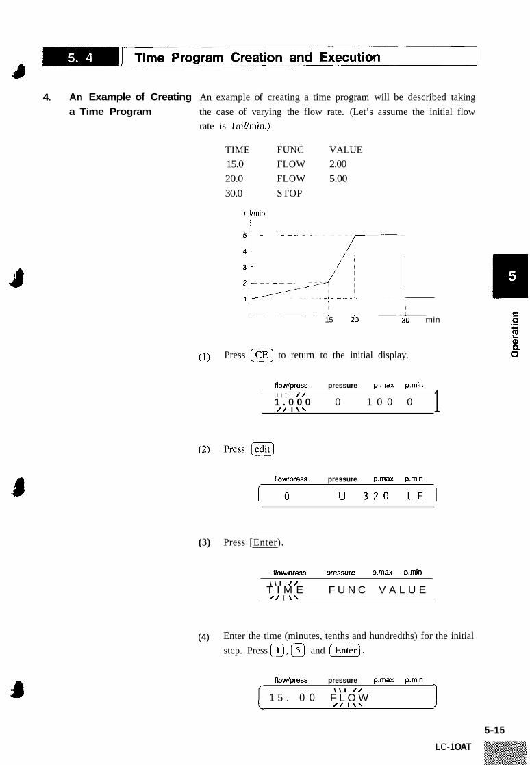
4. An Example of Creating An example of creating a time program will be described taking a Time Program the case of varying the flow rate. (Let’s assume the initial flow
rate is Imllmin.)
TIME FUNC VALUE 15.0 FLOW 2.00 20.0 FLOW 5.00 30.0 STOP
ml/min I
I I I 1 1
15 20 30 min
( 1 ) Press (CEJ to return to the initial display.
flow/press pressure pmax pmin \ \ I / /
1 . 0 0 0 0 1 0 0 0 / / I \ \ 1
flow/press pressure pmax pmin
(3) Press [Enter).
flowhress Dressure mmax amin \ \ I / /
/ / I \ \ T I M E F U N C V A L U E
(4) Enter the time (minutes, tenths and hundredths) for the initial step. Press Q, 0 and (Enter).
flow/press pressure pmax p.rnin \ \ I / /
1 5 . 0 0 F L O W / / I \ \ I
5-15
LC-1 OAT
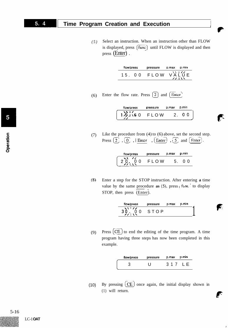
-1 Time Program Creation and Execution /c ( 5 ) Select an instruction. When an instruction other than FLOW
is displayed, press Ifunc) until FLOW is displayed and then press (Enter) .
flow/press pressure p.max p.min \ \ I / /
/ / I \ \ 1 5 . 0 0 F L O W V A L U E
(6) Enter the flow rate. Press @ and [G)
flow/Dress pressure p.max pmin \ \ I /
( 1 5 . / / I \ \ 6 0 F L O W 2 . 0 0 1
(7) Like the procedure from (4) to (6) above, set the second step. Press @ , @ , , [%] , and (Enterj.
flow/press pressure p . m a p.min \ \ I / /
( 2 0 . 0 0 F L O W 5 . 0 0
(8) Enter a step for the STOP instruction. After entering a time value by the same procedure as (3, press to display - STOP, then press (Enter).
flow/press pressure pmax p.min \ \ I / /
3 0 . 0 0 S T O P / / I \ \ 1
(9) Press @ to end the editing of the time program. A time program having three steps has now been completed in this example.
flow/press pressure p.max p.min
3 U 3 1 7 L E
(10) By pressing @ once again, the initial display shown in (1) will return.
dF:
5-16 LC-1 OAT

-1 Time Program Creation and Execution 4
5. Deleting a Step Display the step you want to delete and press (del). The following is an example of deleting the first step of the program created in Section 5.4.4 “An Example of Creating a Time Program.” (1) As in the creation of a program, display the program step
you want to delete.
flow/press pressure p.max p.rnin \ \ I / /
1 5 . 0 0 F L O W 2 . 0 0 / / I \ \ I
(2) Press Idel).
6. LOOP Instruction
<<Cautions>>
flow/press pressure pmax p.min \ \ I / /
/ / I \ \ 2 0 . 0 0 F L O W 5 . 0 0
Now the first step of the program is deleted and the second step is displayed. (This is now the first step of the program.)
Use of the LOOP instruction permits repeating a program at a user- defined time interval for a specified number of times.
TIME FUNC VALUE 0 15.00 FLOW 2.00 Q 20.00 FLOW 5.00
30.00 LOOP 3
With this setting the program will be executed four times; The initial execution plus 3 looped executions for a total time of 120 minutes as illustiated here:
Flow rate ml/min
5c------ I-- ------
I ‘ 30 60 90 120 min Initial value
All steps set (timewise) after the LOOP command are ig- nored, with the exception of a GOT0 command step.
5-17
LC- 1 OAT
-1 Time Program Creation and Execution P
After the LOOP is completed, the program stops automat- ically. If a GOTO instruction exists after LOOP instruction, the pump parameter conditions are maintained until the time of the GOTO instruction; at which time the program executes the GOTO instruction and stops. (See below) A number up to 255 may be set as VALUE for the LOOP instruction. Note, however, that setting 0 means LOOP 256 times. Delete the LOOP step to disable looping. When setting multiple steps, it is not necessary to enter steps in the correct time sequence. The unit sorts the steps auto- matically. Note that a STOP instruction at the last step is usually re- quired except when you want to execute the time program endlessly, or link program files by the GOTO instruction. F
C 7. StarVStop a - .- c, E Q, Q 0
8. GOTO Instruction (File chaining via Time Program execution)
To start or stop a time program that has been completed, follow the procedures below. (1) Starting the Program
Press 0. The vl lamp lights up and the program starts.
To stop the program, two methods are available. One is to forcibly stop it by pressing the STOP key, and the other is to stop by means of a STOP instruction step set in the pro-
(2) Stopping the Program
gram. The case of a forced stop is described here. Press lr..). The -1 lamp is turned off and the program stops.
The GOTO instruction stops the program and switches the active file from the present file to another file whose number is specified in the GOTO instruction argument. After the file is switched, the instrument parameters are set to the initial conditions specified in the new file. The automatic start of the new file’s time program (if extant) is possible by carrying out the following setting. (1) Make connection between the external Input/Output terminals
as illustiated here;
5-18
LC-1 OAT
-1 Time Program Creation and Execution 4
EVENT1
EVENT2
PUMP ON - PUMPOFF -
INPUT PRGSTART - 1 COMMON 1
OUTPUT
PRESSURE
MONITOR
~~ 0 0 -
0 0 0 0
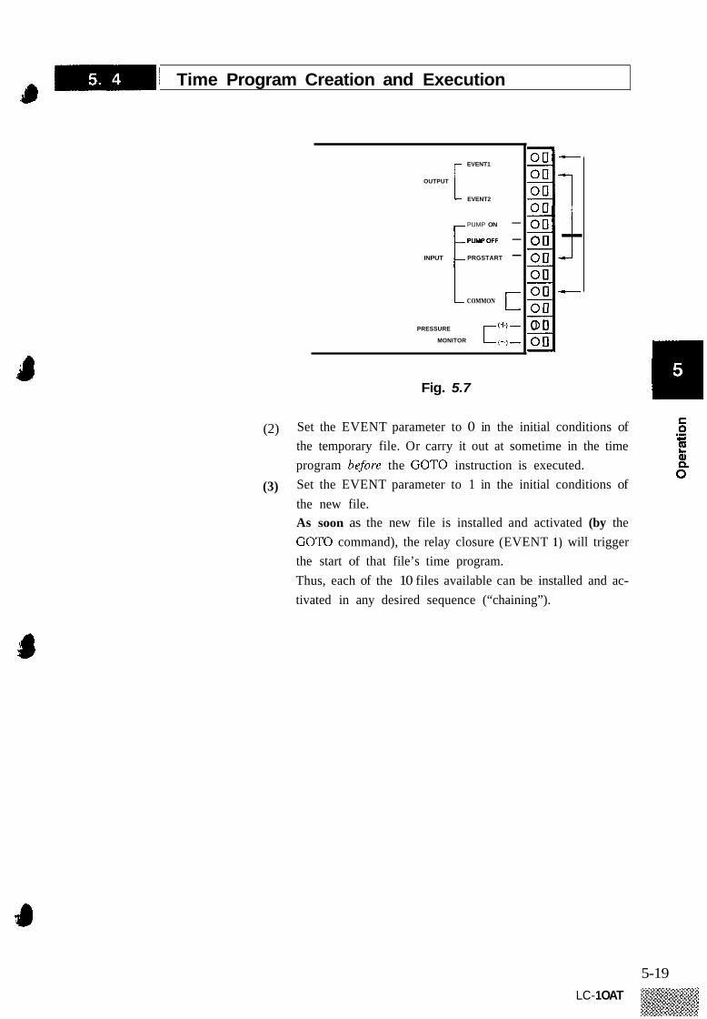
Fig. 5.7
(2) Set the EVENT parameter to 0 in the initial conditions of the temporary file. Or carry it out at sometime in the time program before the GOTO instruction is executed. Set the EVENT parameter to 1 in the initial conditions of the new file. As soon as the new file is installed and activated (by the GOTO command), the relay closure (EVENT 1 ) will trigger the start of that file’s time program. Thus, each of the 10 files available can be installed and ac- tivated in any desired sequence (“chaining”).
(3)
5-19 LC- 1 OAT

Auxiliary Functions (AUX-FUNC) ~
Name
BCONC
7
Factory default value
0
Function
Concentration of solvent B in the gradient elution mode.
1. AUX.FUNC List
ccoNc DCONC FILE NUM FILE COPY
The unit has a number of auxiliary functions (AUX.FUNC). Use of these functions permits a variety of operations to be performed by this device. It is also possible to control the unit from an external device via some of these functions
The following table lists the AUX.FUNC functions. Details of each are on following pages
Concentration of solvent C in the gradient elution mode. 0 Concentration of solvent D in the gradient elution mode. 0 Selects tile. 0 Copies a file. -
Type
I 1
1 1
1
2 1
1
1
I
2
1
1
1
1 I
1
2 2 1
1
1
1
1
1 -
FILE DEL sv EVENT
Deletes a file. - Sets the condition of solenoid valve unit FCV-IOAL or FCV-I IAL. Sets the state of relay contact point output. Lets the EVENT 1 output work as a start signal for a time program.
I 0
EXT-S It also lets the EVENT 2 output work as a stop signal for external 0 equipment in occurrence of an error.
MON TIME MON REV MON ID P-SET COMP
ZERO ADJ CLOSE KEY RANGE SYS
FCV TYPE
LOCAL
P TIMER ADRS
0 Reduces flow rate without stopping the pump when the pressure exceeds the set value of p.max.
S-PROT
--, ~ - ~ -
Monitors elapsed time when running a time program. Monitors accumulated number of pump revolutions. Monitors pump’s ID. 0 Used when replacing the plunger and plunger seal.
0 0
-
0.45 Used for fine adjustment of compensation of solvent compressibility. Carries out zero adjustment for monitoring pressure. Disables key entry.
- -
Sets the span Tor pressure signals in the recorder output. Specifics isochratic or gradient system in use.
10 1
0 Sets the type of solvent selector valve connccted to the S0L.V connector on the rear oT the unit. Selects whether control is made from the system controller ( = I ) or by the pump (=0). Sets the period of purging Sets the address to which the unit is connected.
0
3 1
Monitors solvent dclivcry flow rate in the constant pressurc solvent deliverv mode. MON FLOW I 0
0
BCONC is displayed only when SYS = 2 or 4. CCONC and DCONC are displayed only when SYS = 4.
The type column in the list shows the type of operating method. Type 1: Requires a number argument to execute; key in a value
with the numeric keys then press (E) . Type 2: Press [Enter) to directly execute the function. Tvne 3 : Monitor: The current value (condition) is displayed.
5-20 LC-1 OAT
I Auxiliary Functions (AUX.FUNC) da 2. Setting Procedures for
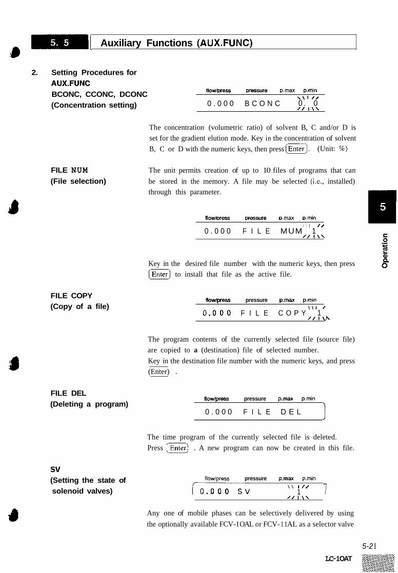
AUX.FUNC BCONC, CCONC, DCONC (Concentration setting)
FILE NUM (File selection)
FILE COPY (Copy of a file)
FILE DEL (Deleting a program)
sv (Setting the state of solenoid valves)
flow/Dress Dressure mrnax p.rnin \ \ I / /
/ / I \ \ 0 . 0 0 . 0 0 0 B C O N C
The concentration (volumetric ratio) of solvent B, C and/or D is set for the gradient elution mode. Key in the concentration of solvent B, C or D with the numeric keys, then press (G). (Unit: %)
The unit permits creation of up to 10 files of programs that can be stored in the memory. A file may be selected (i.e., installed) through this parameter.
flow/Dress Dressure D.rnax mmin \ \ I / /
/ / I \ \ 0 . 0 0 0 F I L E MUM 1
Key in the desired file number with the numeric keys, then press [G) to install that file as the active file.
flow/press pressure p.rnax pmin
0 , 0 0 0 F I L E C O P Y 1 \ \ I /
The program contents of the currently selected file (source file) are copied to a (destination) file of selected number. Key in the destination file number with the numeric keys, and press (Enter) .
flow/press pressure p.rnax pmin
0 . 0 0 0 F I L E D E L
The time program of the currently selected file is deleted. Press (G) . A new program can now be created in this file.
flow/press pressure pmax p.rnin \ \ I / /
1 7 Any one of mobile phases can be selectively delivered by using the optionally available FCV-1 OAL or FCV- 1 1 AL as a selector valve
5-2 I LC- 1 OAT

1 Auxiliary Functions (AUX.FUNC) I,
Solenoid Valve type
at the pump inlet. Key in the value corresponding to the desired mobile phase with a numeric key, then press ( G I to switch the value.
Argument Selected mobile phase
<<Note>>
0
1
2
3
FCV- I I AL
FCV.TY PE (Specification of type of solenoid valve module)
All chaiiiiels arc sct to thc A side.
Channel I is set to the B side.
Channel 2 is set to the B side.
Channel 3 is set to the B side.
EVENT (Setting EVENT relay states)
Argument
0
Solenoid valve module
FCV- I OAL
I Solvent A I I ' I
1
I I I
FCV- 1 1 AL
Solvcnt B
Solvent C
2
3 FCV- I OAL
I I I I
Solvent D 4
Solenoid valve type I Argument I Selected mobile phase
In use, combine the arguments to select multiple channels.
Example: By setting SV 123, channels I , 2 and 3 are all set to the B sidc.
Before setting SV, specify the kind of solenoid valve unit installed with the FCV TYPE parameter. See next.
flow/press pressure p.max p.min \ \ I / /
/ / I \ \ 0 . 0 0 0 F C V T Y P E 1
The optional solvent selector valve to be connected to the S0L.V connector on the rear of the unit is specified with this parameter. Key in the appropriate value with a numeric key, then press (Enter) to register the flow control value type.
(R* .
flow/press pressure p.max p.min \ \ I / /
/ / I \ \ 0 0 . 0 0 0 E V E N T
ON (contacts closed) and OFF (contact open) of the EVENT relay contacts (on the rear of the module) are set. Key in the desired value with the numeric keys then press (E] to activate/deactivate the relay(s).
F 5-22

I Auxiliary Functions (AUX.FUNC) @
12
EXT-S (External signals) (Function setting for the EVENT relay terminals)
Relay 1 ON Relay 2 ON
<<Note>>
Argument
0
1
S-PROT (Setting the system protection function)
Function
Cancels the system protection.
Activates the system protection.
Relay I OFF Relay 2 OFF
Relay 1 O N Relay 2 OFF
Relay I OFF Relay 2 ON
flow/oress Dressure omax D.min
I \ \ I // 0.000 E X T - S 1
Sets control mode for the EVENT output (relays 1 and 2). key in the argument with a numeric key, then press [GI.
I Argument I Function I Relays are controlled by the value set to EVENT. (Normal default condition)
Relay 1 (EVENT I ) is used as a start output signal when the time program starts. (Event 2 operates normally)
1
Relay 2 (EVENT 2) is used as an error output signal. (Event I operates normally)
Combination of functions 1 and 2. (Normal EVENT 112 operations are disabled.)
The use of the EXT-S function disables normal operation of the EVENT parameter relevant to the corresponding EVENT terminal. Use care.
flowlpress pressure p.max p.rnin r
1 \ \ I / / I 0.000 S - P R O T 0
S-PROT controls solvent delivery in such a manner that when the P.MAX limiter is activated, flow rate is reduced by one half without stopping the pump, until the flow rate becomes lower than the P.MAX value. (Normally, exceeding P.MAX causes the pump to stop.) Key in the argument with a numeric key, then press [Enter).
To cancel the P.MAX error alarm, press ICE).
5-23 LC-1 OAT

I Auxiliary Functions (AUX.FUNC) 1,
Argument
0
1
MODE CHANGE (Selecting the solvent delivery mode)
Function
Cancels the flow rate display function.
Activates the flow rate display function.
<<Note>>
Argument
0
1
flow/press pressure p.max p.min
0 . 0 0 0 M O D E C H A N G E
Switches between the constant flow solvent delivery mode and the constant pressure solvent delivery mode. Press (Enter) to select the desired solvent delivery mode. The selected mode is indicated by lighting of either the C.PRESS or C.FL0W LED.
Function
Cancels monitoring of the elapsed time of the time program.
Activates monitoring of the elapsed time of the time program.
The pump should not be in operation when switching the solvent delivery mode.
MON FLOW (Displaying flow rate in the constant pressure solvent delivery mode)
flow/press pressure p.max p.min \ \ I / /
/ / I \ \ 0 . 0 0 0 MON F L O W 0
Displays the approximate flow rate when in the constant pressure solvent delivery mode. Key in the argument with a numeric key, then press (Enter).
MON TIME (Monitoring the elapsed time of the time program)
MON REV (Monitoring the accumulated number of pump revol u t i ons)
flow/press pressure p.max p.min \ \ I / /
/ / I \ \ 0 . 0 0 0 MON T I M E 0
flow/press pressure pmax p.min \ \ I / /
/ / I \ \ 0 . 0 0 0 MON R E V 0
F
The accumulated number of pump revolutions is monitored. It
P counts up to 16,777,215, then resets to 0. Key in the argument with a numeric key, then press (Enter).
5 -24 LC- 1 OAT

1 Auxiliary Functions (AUX.FUNC) 4
1
MON ID (ID indication for remote control)
Enables the ID indication.
P-SET (Plunger set)
I Argument I Function
Cancels monitoring the accumulated number of pump revolutions.
Activates monitoring the accumulated number of pump revolutions.
0
1
The accumulated number of pump revolutions serves as an indicator for seal replacement. It is recommended to replace the seals every 2.5 million revs, i.e., approx. every 2000 hours (at 1 mllmin, 100 x lo5 MPa using water).
flow/oress Dressure Dmax a m i n \ \ I / /
0 . 0 0 0 M O N I D 0 / / I \ \ 1
If the unit is connected to the SCL-IOA, the pump connection ad- dress (A, B or C on the SCL-IOA) is indicated in the initial display. Key in the argument with a numeric key, then press (Enterj.
I I Argument I Function
1- o 1 Disables the IDindication.
flow/press pressure pmax o.min
I 0 . 0 0 0 P U M P A
If the SCL-IOA is not connected, the following will be displayed.
flow/press pressure pmax p.min
0 . 0 0 0 N O T L I N K E D
flow/press pressure pmax pmin \ \ I / / \ - 0 - - / / I \ \
0 . 0 0 0 P - S E T
Moves the plungers and stops them in the home position for seal replace men t . Key in the argument with a numeric key, then press (Enterj.
5-25 LC- 1 OAT
C 0 .- 4-
!!
0 a Q
Water
Acetone
I Auxiliary Functions (AUX.FUNC) ' c
0.45
1.24
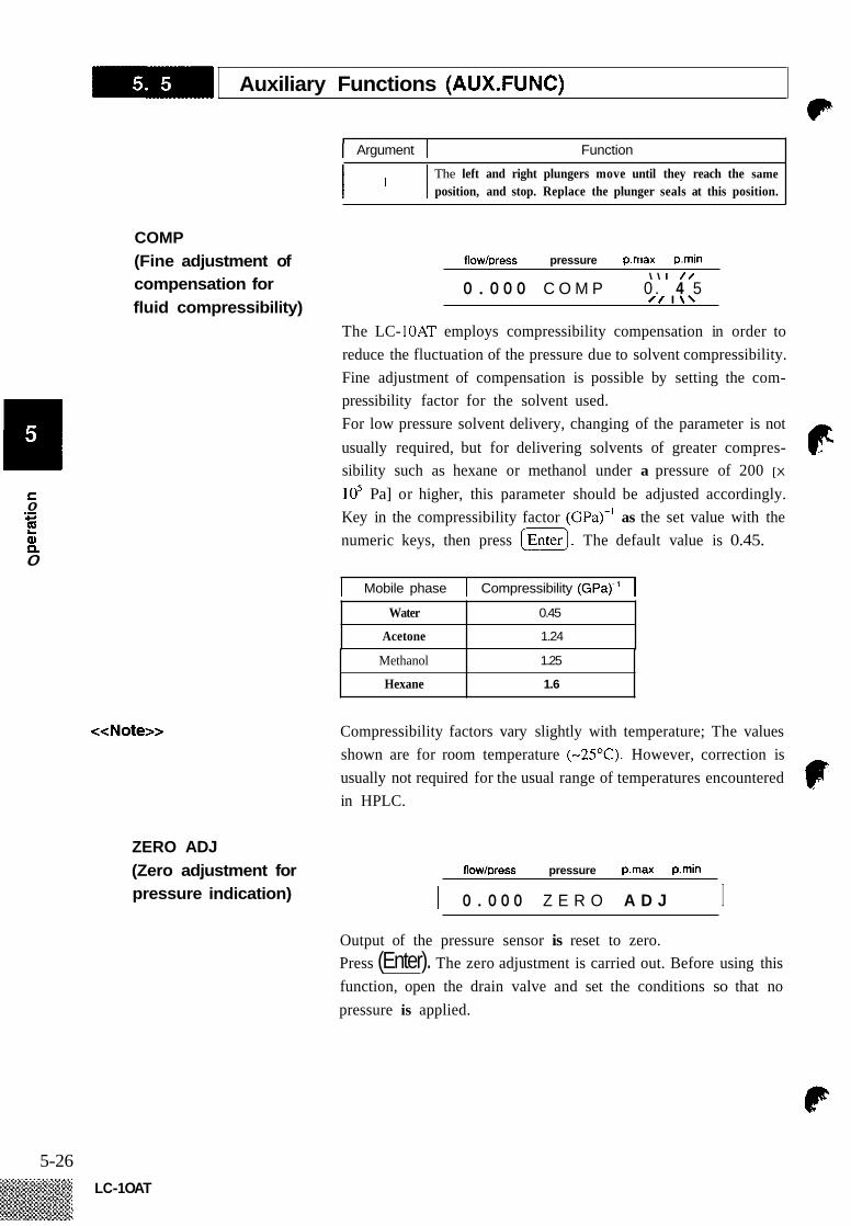
COMP (Fine adjustment of compensation for fluid compressibility)
Methanol
Hexane
<<Note>>
1.25
1.6
ZERO ADJ (Zero adjustment for pressure indication)
I Argument 1 Function
The left and right plungers move until they reach the same position, and stop. Replace the plunger seals at this position.
flow/press pressure p.rnax pmin \ \ I / /
/ / I \ \ 0 . 4 5 0.000 C O M P
The LC- l0AT employs compressibility compensation in order to reduce the fluctuation of the pressure due to solvent compressibility. Fine adjustment of compensation is possible by setting the com- pressibility factor for the solvent used. For low pressure solvent delivery, changing of the parameter is not usually required, but for delivering solvents of greater compres- sibility such as hexane or methanol under a pressure of 200 [X
lo5 Pa] or higher, this parameter should be adjusted accordingly. Key in the compressibility factor (GPa)-' as the set value with the numeric keys, then press [ G I . The default value is 0.45.
I Mobile phase I Compressibility (GPa)-' I
Compressibility factors vary slightly with temperature; The values shown are for room temperature (-25°C). However, correction is usually not required for the usual range of temperatures encountered in HPLC.
flow/press pressure p.rnax p.rnin
I 0.000 Z E R O A D J I Output of the pressure sensor is reset to zero. Press (Enter). The zero adjustment is carried out. Before using this function, open the drain valve and set the conditions so that no pressure is applied.
5-26 LC-1 OAT
I Auxiliary Function (AUX.FUNC) -8 1
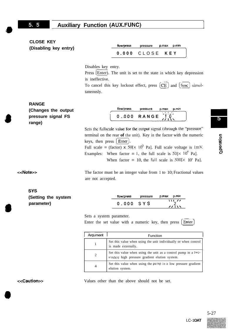
CLOSE KEY (Disabling key entry)
Disables key 1
flow/press pressure p.rnax p.min
0 . 0 0 0 C L O S E K E Y
entry. Press [Enter). The unit is set to the state is ineffective. To cancel this key lockout effect, press
in which key depression
@ and a simul-
<<Note>>
SYS (Setting the system para meter)
taneously.
1 0.000 R A N G E -1 .0 ‘ I
RANGE (Changes the output pressure signal FS range)
c 0
Q, Q
terminal on the rear of the unit). Key in the factor with the numeric keys, then press (Enterj.
Examples:
.- c I
Full scale = (factor) x 50[x 10’ Pa]. Full scale voltage is ImV. 0 When factor = 1, the full scale is SO[x lo5 Pa].
When factor = 10, the full scale is SOO[x 10’ Pa].
The factor must be an integer value from 1 to 10; Fractional values are not accepted.
flow/press pressure p.max p.rnin \ \ I / /
0 / I \ \ 2 0.000 S Y S
Sets a system parameter. Enter the set value with a numeric key, then press [G]
rArgument I Function I Set this value when using the unit individually or when control is made externally.
Set this value when using the unit as a control pump in a two- niodule high pressure gradient elution system.
Set this value when using the pump i n a low pressure gradient elution system.
1
2
4
<<Caution>>
~~
Values other than the above should not be set.
5-27 LC- 1 OAT

1 Auxiliary Function (AUX.FUNC) P
3 - I6
LOCAL (Setting the control mode) flow/press pressure p.max p.min
\ \ I / /
/ / I \ \ 0 0.000 L O C A L
In the case when the unit is connected to the SCL-IOA, ADRS should be set to the port number of the SCL-IOA to which the unit is connected.
By setting this function when the unit is linked with SCL-IOA, the unit can be operated independently. Key in the argument with a numeric key, then press I%). I Argument Function I I 0 I Control is made by the SCL-IOA. I I 1 I The module is operated independently (local mode). I
P TIMER flow/press pressure p.max p.min
0.0 0 0 P TIMER (Setting the period of purging)
// I \ \
Sets the period of purging (min). Key in the required purge time with numeric keys, then press [Enter 1. A value from 0.1 to 9.9 (min) can be selected.
ADRS (Setting the REMOTE address) flow/press pressure p.max p.min
\ \ I / /
/ / I \ \ 0 . 0 0 0 A D R S 3
If the unit is connected to the SCL-1OA system controller or another
parameter. Key in the address number with the numeric keys, then press
LC-IOAT. the connection address should be stated with this
F enter 1.
Function
In the case when the unit is connected to another LC-IOAT, I 85 I ADRS should be set to 85.
Values other than the above should not be set.
5-28 LC-1 OAT

High Pressure Gradient Elution Mode
io High pressure gradient elution is possible by controlling the 2 or 3 LC-1OATs in the system from the SCL-IOA system controller, or by connecting two LC-IOATs with each other in such a manner that one of them (the “master”) controls the other (the “slave”). The latter setup will be described here. For the operating method for control by the system controller, see the System Controller Instruction Manual.
1. Preliminary Setting ( I ) Set system parameters for the master LC-IOAT (called pump A) that controls the other (pump B) as follows:
SYS = 2 ADRS = 85
(2) Set system parameters for the slave LC-IOAT (called pump B) that is to be controlled as follows:
SYS = 1 ADRS = 85
For the procedures for setting the system parameter, see Sec- tion 5.5 “Auxiliary Functions (AUX.FUNC).” Set the upper limit pressure (P.max) and lower limit pressure (P.min) for each pump. Values P.max and P.min set at each pump are effective. From now on operation is carried out from the master pump A only. It is advised to lock the keys of pump B to prevent misopera- tion.
( 3 )
2. Setting Initial Conditions (1) Set the total flow rate of the mobile phase (through the column, i.e., total flow rate of pump A and B) as the flow rate of pump A.
(2) Refemng to Section 5.5 “Auxiliary Functions (AUX.FUNC),” enter the concentration value for solvent B (unit: %) to parameter BCONC. The concentration of solvent of pump A (ACONC) is as fol- lows.
ACONC(%) = loo(%) - BCONC(%) For the BCONC parameter, settable range is from 0 to loo%, and the minimum step is 0.1%.
( 3 ) By pressing [ E l on pump A, pumps A and B starts sol- vent delivery simultaneously.
3. High Pressure Gradient Delivery Program
By setting the concentration of solvent B in a time program, it is possible to change concentration of solvent A and B linearly (in- verse percentage ratio) on a time basis.
* 5-29
LC- 1 OAT

[ High Pressure Gradient Elution Mode
4. An Example of Program ( 1 ) Call the time program editor screen. (Press .)
Setting (2) Enter a time.
(3) Press =until BCONC is displayed on the setting screen, and then press IEnterl].
(4) Enter concentration. The following is an example of setting for changing the concentra- tion through a time program. (See Section 5.4 “Time Program Creation and Execution”.) Initial value for BCNC: 0.0
TIME FUNC VALUE 10.00 BCONC 25.0 20.00 BCONC 100.0 30.00 BCONC 100.0 30.10 BCONC 0.0 40.00 STOP
The program above results in a binary gradient elution in which the concentration of the solvent B can be graphically illustrated, as follows.
100%
BCONC
25%
n stop
I I --- - 0 10 20 30 40 50 60 min
Time - Note that the concentration delivered at any given time is based on a linear interpretation of proportionality between each defined point. (Nonlinear curves are available by control with the SCL- 1 OA.)
5. Operation of Pump B (1)
(2)
Pump A controls flow rate of pump B, but all parameters of pump B except the flow rate (FLOW) are effective. The (=) key of each pump is always effective, so that pressing the (El key starts or stops delivery even if it is controlled by a time program of pump A. When not delivering, pressing the (G) key will allow for purging.
(3)
5-30
-1 High Pressure Gradient Elution Mode a <<Caution>> Do not press the [RUN) key on pump B.
If [E) key is pressed, the time program (if any) in pump B will also start. This may result in faulty solvent delivery.
5-3 1
LC-1 OAT

Low Pressure Gradient Elution Mode
P The module by itself allows running of a binary, ternery or quarter- nary low pressure gradient elution. (It is also possible to carry out the setting from the SCL-1OA system controller.) The following is a description of setting a quarternary (A, B, C, and D) gradient elution using a single LC- 1 OAT equipped with a selector value and mixer, as described in Section 4.10.
1. Preliminary Setting (1) (2)
Enter 4 at the system parameter SYS of AUX.FUNC. Enter total flow rate of the mobile phase (sum of flow rates of four liquids A, B, C and D) for the set value of the flow parameter. Set the flow rate to 5mNmin here as an example. Next, set concentration parameters. As an initial operation is being done here, setting is made so that each flow rate is equal to fill all the flow lines with the liquids. Set each of BCONC, CCONC and DCONC to 25%. (See Section 5.5 "( AUX .FUNC)". Concentration of liquid A (ACONC) is as follows.
(3)
ACONC(%) = loo(%) - BCONC(%) - CCONC(%) - DCONC(%)
For parameters BCONC, CCONC, and DCONC, the setting range is from 0 to loo%, and the minimum step is 0.1 %.
<<Note>>
2. Initial Operation
Key input is automatically rejected if an attempt is made to enter a concentration to BCONC, CCONC or DCONC which causes the total conc. to exceed 100%.
(1) Open the drain valve.
(2) Press (pump) to start the pump. u
(3) Draw the mobile phase from the pump outlet to fill the flow line with the mobile phase. Make sure that no bubbles are in the flow line. Purge the flow line with the mobile phase for about 10 minutes. Press (pump) to stop the pump, and close the drain valve.
(4) ( 5 )
(6)
3. Low Pressure Gradient (1) Set the (total) flow rate and the concentration(s) to the prescribed values, then press (pump) to start solvent delivery. Operation
4. LOW Pressure Gradient Delivery Program
By setting concentration of liquids B, C, and D at certain times in a time program, it is possible to vary the concentrations of liquids A, B, C, and D in linear proportions on a time basis. E
5-32 LC-1 OAT

Plunger Washing Method 0
1. Connections (1) Connect the accessory Teflon tubes with the two Teflon tubes at the bottom of the head holder by using the accessory vinyl tubes. Place the open end of one of the Teflon tubes into a waste container.
(2)
Container such as beaker
flowing direction
Disposable syrings
Fig. 5.0
Drai
Jo i n tef I on tubes with a
5-33 LC- 1 OAT

-1 Plunger Washing Method ‘ 6
Fill the disposable syringe with washing solution and insert the needle end into the rinsing tube. Force the washing solution through the washing flow line. It is possible to conduct the washing irrespective of whether the pump is running or not. Typical periods for manual washing are as follows. Phosphoric acid buffer solution (low concentration) : A few timeslday Boric acid buffer solution (low concentration) : Several timeslday
Use of a buffer solution as the mobile phase will produce crystalline salts upon evaporation of the solution, and which can damage the plunger and plunger seal and shorten their service life. When using a buffer solution, accordingly, it is recommended to wash the flow line frequently. Continuous washing can be done using an inex- pensive peristaltic pump or the like to pump water through the wash line at a few mllmin.
5-34 LC-1 OAT

Change of Mobile Phase
As a mobile phase may be or may not be miscible with another, or as the use of buffer solutions requires extra care in handling, change of a mobile phase should be conducted correctly according to the following description. If you also change the column to a different type, remove the first column and carry out the procedure before installing the next column.
1. Change between (1)
(2) Miscible Mobile Phases
(3)
Rese mobi
Put approx. l0Oml of the fresh mobile phase into a container of 200mf capacity. Take out the suction filter from the first reservoir and swirl it around in the lOOml of fresh mobile phase to remove as much of the old mobile phase from the accessable surfaces of the filter and its tube. Put the suction filter into a newly prepared reservoir filled with fresh mobile phase, open the drain valve, and press (G] to purge the previous mobile phase completely out of the flow line.
/ \ Drain port
Direction of
Open 1 (Turn knob
:he drain valve the drain valve counterclockwise.)
Waste container
E C
0 .- CI
!? a 0"
Fig. 5.10
5-35 LC- 1 OAT

-1 Change of Mobile Phase bc
(4) Break open the connection at the outlet of the manual injector and pipe the outlet to a waste container. Set the flow rate to 2-3mllmin then close the drain valve. Switch the injector between the load and inject positions and hold each position long enough to allow the sample loop and inner passages to be flushed. Thus, the mobile phase in the manual injector will be replaced.
Pump outlet Close the d ra in valve (Turn the d ra in valve knob c l o c k w i s h
Reser fresh
he inside of the manual injector
Pump inlet Waste
mobi le phase u Fig. 5.11
( 5 ) Reconnect the outlet of the manual injector, then replace the mobile phase in components in the flow line that follow the manual injector. Flow rate should be so adjusted that the delivery pressure does not exceed the permissible pressure rating of the column.
The inside of the
fresh mobi le Dhase
Fig. 5.12
5-36
’ Close the d ra in valve /(urn the d ra in valve knob cI
waste contain- er o r connect w i th a detector.
Manual injector
Reservoir f i l led w i th

-1 Change of Mobile Phase
2.
3.
Change between Immiscible Mobile Phases
(1) Prepare an intermediate washing solution (such as isopropyl alcohol) that is miscible with both previous and next mobile phases. Replace the old mobile phase with the intermediate washing solution. See procedures ( 1 ) to ( 5 ) of Section 5.9.1 “Change between Miscible Mobile Phases.” Replace the intermediate washing solution with the fresh mobile phase. See procedures ( 1 ) to ( 5 ) of Section 5.9.1 “Change between Miscible Mobile Phases.”
(2)
( 3 )
Replacement of Buffered Use of a buffered mobile phase may result in crystalline substances Mobile Phase being deposited upon dehydration or evaporation of the solution.
Accordingly, replace the buffer solution as follows. Note that if an organic solvent such as isopropyl alcohol is delivered, strongly bound salt deposits may form, so care should
5 be taken. (1 ) Prepare distilled or deionized water. c
(2) s 4
.-
Feed 200ml or more of the water to wash out the buffer soh- tion. See procedures ( 1 ) to ( 5 ) of Section 5.9.1 “Change be- tween Miscible Mobile Phases.” Then replace the water with the fresh mobile phase. See pro- cedures ( 1 ) to ( 5 ) of Section 5.9.1 Change between Miscible Mobile Phases.”
(3 )
4. Use of Washing Flow Line
<<Caution>>
Use of a buffered mobile phase may result in the deposit of crys- talline substances upon dehydration or evaporation of the solution: These salts can damage the plungers and plunger seals and shorten their service life. When using a buffer, it is advisable to frequently or continuously wash the back side of the plunger seals and plunger surfaces by pumping water through the built-in wash line. For the washing method, see Section 5.8 “Plunger Washing Method.”
If you are not going to use the unit for some time (hours +) after feeding a buffer solution, replace the contents of the flow line with distilled or deionized water to prevent salt formation and deposition.
5-37 LC- 1 OAT

Chapter 6 Performance Checking \ m
Contents
6.1 Operation Checking for Simple Isochratic System .................... 6-2
6.2 Checking Concentrations in High Pressure Gradient Elution . . . . . . . . . . . 6-5
6.3 Checking Concentrations in Low Pressure Gradient Elution . . . . . . . . . . . 6-7
6- 1
LC-1 OAT

w C Y 0 Q) c 0
.-
Q) 0 S (II
E 5 t n rc
Operation Checking for Simple lsochratic System 0
Operation checking for a simple isochratic system, as shown in the following illustration, is described here.
Detector (SPD-1 OA) t I R e s e r v o 7 r& Column oven (CTO-IOA)
Manual injector (7125)
700 Pump (LC-IOAT)
1. Preparation
2. Connection
3. Operation
Resei Fvoi r box
I I I I
- Chromatopac(C
I
-R6A)
Approx. 540m
LC-1 O A T C T 0 - 1 0 A s p D- 1 0 A Chromatopac
Pump Manua l Column Detector injector
E lectr ica I connection Reservoir
Fig. 6.1
(1)
(2)
Connect the input terminal of the Chromatopac and AUX terminal of SPD-1OA by using the signal cable and terminal block included in the accessories for the Chromatopac and the signal cable included in the accessories for the SPD-IOA.
Prepare as many reservoirs as required. Prepare an appropriate mobile phase and sample. e
Switch power on for the whole system. Purge the flow line (from the suction filter to the pump drain). Close the drain valve and operate the pump at Imflmin. Check that the pressure is stable and liquid is flowing from the outlet of the SPD-IOA. Set the temperature of the CTO-IOA to 40°C. On the SPD-IOA, set the wavelength to 254nm, response to
1) 4, and AUX RNG to 3. (The AUX output range becomes 2AUN.)
6-2
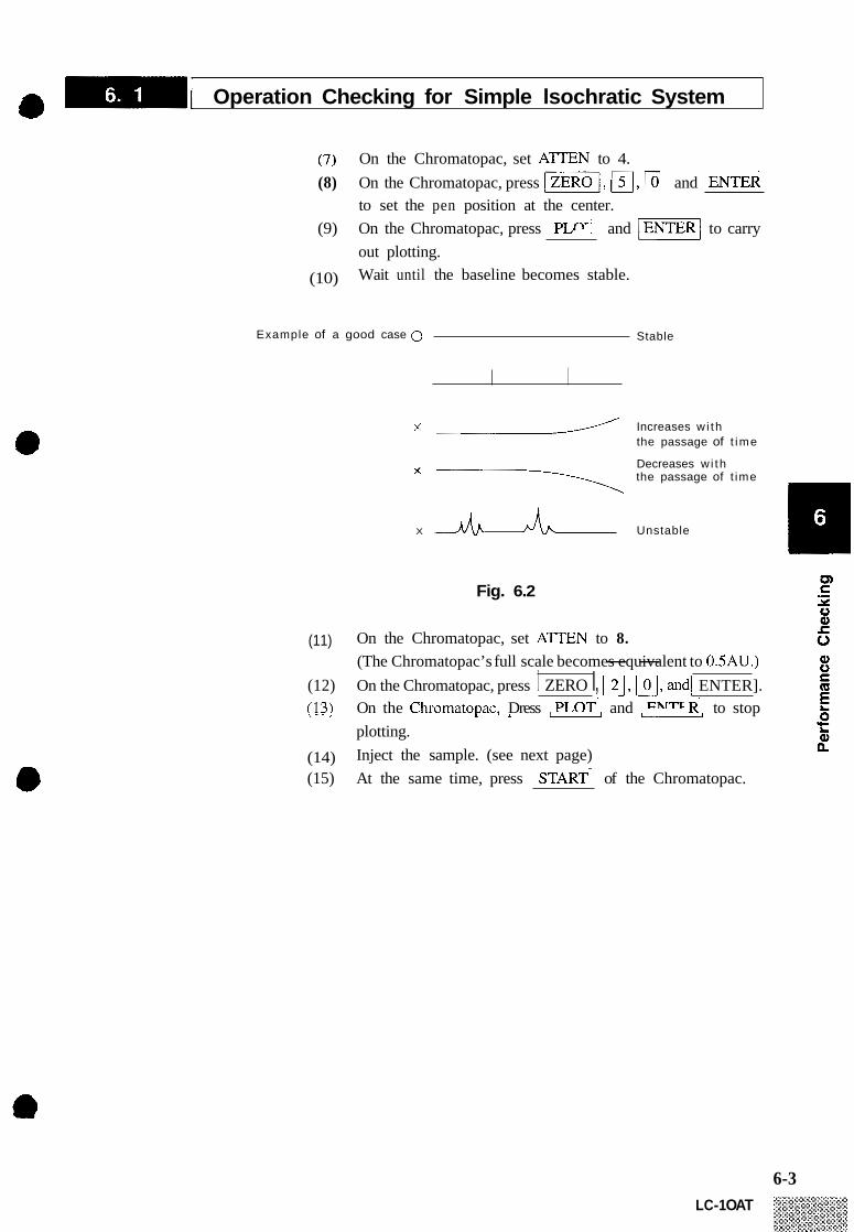
I Operation Checking for Simple lsochratic System a (7) On the Chromatopac, set ATTEN to 4. \ I
(8) On the Chromatopac, press w/, m, and to set the pen position at the center.
out plotting. Wait until the baseline becomes stable.
(9) On the Chromatopac, press and -1 to carry
(10)
Example of a good case 0 Stable
x -/ Increases w i th the passage of t ime
Decreases w i th -\ the passage of t ime
X Unstable
Fig. 6.2
(11) On the Chromatopac, set A T E N to 8. (The Chromatopac’s full scale becomes -- equivalent to 0.5AU.)
(12) On the Chromatopac, press I ZERO I, w, w, and1 ENTER]. (13) On the ChromatoDac. Dress and to stop , - - I I , I u -
plotting. Inject the sample. (see next page) (14)
(15) At the same time, press of the Chromatopac.
6-3 LC-1 OAT

I Operation Checking for Simple lsochratic System '. 4. Example of Analysis The following is an example of the performance check under the
(conditions) conditions below: Mobile phase : Column : Shim-pack CLC-ODS 6.0mma x 15cm Flow rate : 1 mllmin
HzO/Acetonitrile = 15/85
: Wavelength 254nm, response 4 Sample: : Naphthalene 1 Omg
Biphenyl in lOOml Acenaphthene 30mg Methanol Anthracene Pyrene 1 Omg
(results)
START 1
2.597
c-
&&!!I 6.358 f 6.882
C H R O M A T O P R C C-R6R S A M P L E NO 0 R E P O R T NO 51 5
P K N O T I M E R R E R M K I D N O
1 4 . 8 5 7 21 431 9 2 5 . 4 4 593455 s u 3 6 I 358 241558 U 4 6 . 8 8 2 751233 U 5 8 . 4 6 3 599924
2 4 8 8 9 8 7 - - - - - - - - -
T O T A L
F I L E 0 M E T H O D 41
C O N C N R M E
8 , 947 1 Naphthalene
2 4 , 7 1 7 1 1 0 . 8 6 8 3 3 1 , 2885 Anthracene
Biphenyl
Acenaphthene
2 4 , 9865 Pyrene
6-4

Em- The concentration of each solvent in high pressure gradient elution can be tested without a column or sample in the following method.
Checking Concentration in High Pressure Gradient Elution
1. Conditions
2. Specification
8 3. Precautions for Measurement
Solvent A : 0.3% acetone in water B : Distilled water
Flow rate : lmZ/min Load pressure : 10 - 30 [x105 Pa] Measurement wavelength : 254nm
At liquid A concentration ratios of 10, 50 and 90%, the concentra- tion error should be within f l % .
Be sure to degas the mobile phase. Open the drain valve and wash the flow line for 5 minutes, with the flow rate set to 9mUmin and BCONC parameter to 50%. Then set the flow rate to 3mNmin. Close the drain valve and wash the flow line for 20 minutes.
rn X 0
Last, set the flow rate to 2mUmin and the BCONC parameter to 100%. and check that the baseline has become stable, then
.- c start measurement. ti3 c
0
4. Measurement Example Initial parameter setting Row rate : lmZ/min BCONC : 100
I 100% I Time program TIME FUNC 0.10 BCONC
10.00 BCONC 10.10 BCONC 20.00 BCONC 20.10 BCONC 30.00 BCONC 30.10 BCONC 40.00 BCONC 40.10 BCONC
VALUE 90.0 90.0 50.0 50.0 10.0 10.0 0.0 0.0
100.0
6-5 LC-1 OAT

6-6
-1 Checking Concentration in High Pressure Gradient Elution 1 Calculation
= 10% actual concentration A10 A100
A50 A100
= 50% actual concentration
A90 = 90% actual concentration
A100
It is possible to read values of AIO, A50, A90 and A100 directly from the recorder chart, however, this method yields serious errors. Accordingly, it is recommended to run the following BASIC pro- gram on the Chromatopac, to print out the LEVEL.
BASIC PROGRAM 10 PRINT LEVEL; 20 WAIT 60 30 GOT0 10
LC-1 OAT

1.
2.
3.
4.
Conditions
Specification
Precautions for Measurement
Measurement Example
Solvent A : 0.3% acetone water solution Solvent B, C, and D : Distilled water Flow rate : lmNmin Load pressure : 10 - 30 [x105 Pa] Measurement wave length : 254nm
At Solvent A mixing ratios 10, 50, and 90%, concentration error f2% maximum
Be sure to degas the mobile phase. Open the drain valve and wash the flow line for 5 minutes, setting the flow rate to 5mllmin and BCONC, CCONC, and DCONC parameter to 25%. In this case, be sure to connect the unused inlets with the reservoir and conduct replacement with either solution used. Then set the flow rate to 2mllmin. Close the drain valve and wash the flow line for 20 minutes. Last, set the flow rate lmllmin and the BCONC parameter to loo%, CCONC and DCONC parameters to 0% and check that the base line has become stable, then start measurement.
Low pressure gradient Elution using Solvent A and B
10%
0% Start
100%
r
0 0
Q:
Initial parameter setting Flow rate: lml/min B.CONC : 100.0 C.CONC : 0.0 D.CONC : 0.0
CD S Y 0 Q) r
Q) 0 C Q E 0 't Q) n
.-
0
L
6-7 LC-1 OAT

1 Checking Concentration in Low Pressure Gradient Elution ' * Time program
TIME 0.10
10.00 10.10 20.00 20.10 30.00 30.10 40.00 40.10
FUNC BCONC BCONC BCONC BCONC BCONC BCONC BCONC BCONC BCONC
VALUE 90.0 90.0 50.0 50.0 10.0 10.0 0.0 0.0
100.0
Calculation
= 10% actual concentration A10 A100
= 50% actual concentration A50 A100
A90 A100
= 90% actual concentration
It is possible to read values of A10, A50, A90 and A100 directly from the recorder chart, however, this method yields serious errors. Accordingly, it is recommended to nin the following BASIC pro- gram on the Chromatopac, to print out the LEVEL.
BASIC PROGRAM 10 PRINT LEVEL; 20 WAIT 60 30 GOT0 10
Q) 0 S
E
6-8 LC-1 OAT

Chapter 7 Control from External Equipment
7.1
7.2
Connections of External Equipment to the InputIOutput Terminals . . . . . . 7-2
Control from the SCL-IOA . . . . . . . . . . . . . . . . . . . . . . . . . . . . . . . . . . . . . . . 7-4
7-1

Description Remarks _ _ ~ ~~
Reed relay contact point output. The contact points close and open according to EVENT parameter values set in a program or AUX.FUNC setting.
Reed relay contact point output. The contact points close and open according to EVENT parameter values set in a program or AUX.FUNC setting.
The pump in the unit can be started by the external contact point signal through this terminal.
The pump in the unit can be stopped by the external contact point signal through this terminal.
The time program for the unit can be started by the external contact point
The rated values of the reed relay contact points are 30VDC and 0 . 1 ~ .
Control is made by short-cir- cuiting these signal terminals and “COM’ terminal. The closure time (tc) should be as follows: 0 . 5 ~ ~ ~ < tC < losec, ice.,
Connections of External Equipment to the Input/Output Terminals
8 1. The InpuUOutput Terminals
on E EVENT1
on OD c EVENT2
on on on
- - PUMP ON -
PUMPOFF - PRG START - on INPUT
0 0 on C COMMON on
PRESSURE
MONITOR OCI
Fig. 7.1
Signal name
EVENT 1
EVENT 2
ON (PUMP)
OFF (PUMP)
PRG START
COMMON
signal through this terminal. 500ms or more I
Common terminals for ON, OFF, START, and STOP signals.
PRESSURE MONITOR
Outputs pressure values. The output scale may be set in ten steps within an output range of (0 - 50 [x los Pa]) to (0 - 500 [x lo5 Pa]). See Section 5.5 “Auxiliary Functions (Aux. FUNC)”
Full scale voltage = ImV
7-2

a m [ Connections of External Equipment to the InpWOutput Terminals
2. Wiring
<<Caution>>
(1) Strip the insulation from the end of the connecting wire to leave approx. lOmm of exposed conductor. This treatment is not necessary for the accessory remote cable. If the core wire is solid, just insert it into the hole of a ter- minal. If it is stranded, twist the end well, then insert it into the hole while pressing the button on the right side using a small screwdriver or the like. To disconnect the cable, press the button and pull the cable.
(2)
insulation
Appvox. lOmm Push this button to insert/withdraw wires
core -
Fig. 7.2
The accessory remote cable can be used for the wiring. If additional wire is required, carry out wiring with the following wires. Solid wire : Q0.4 - 01.0 (AWG26 - IS) Stranded wire: 0.3mm2 - 0.75mm’ (AWG22 - 20)
Element wire diameter: ~ 0 . 1 8 at the minimum To protect the wire from breaking, stranded wire is recommended. Twisted-pair cable composed of stranded wire with the exposed ends well tinned with solder is most highly recommended.
t Y
k w
7-3 LC-1 OAT
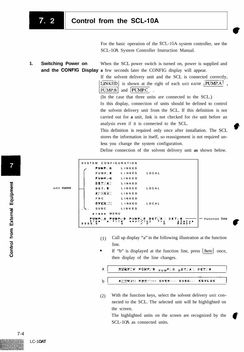
Control from the SCL-IOA ~
For the basic operation of the SCL-1OA system controller, see the SCL-1 OA System Controller Instruction Manual.
1. Switching Power on and the CONFIG Display a few seconds later the CONFIG display will appear.
When the SCL power switch is turned on, power is supplied and
If the solvent delivery unit and the SCL is connected correctly, -1 is shown at the right of each unit name v] , -1 and -1 . (In the case that three units are connected to the SCL.) In this display, connection of units should be defined to control the solvent delivery unit from the SCL. If this definition is not carried out for a unit, link is not checked for the unit before an analysis even if it is connected to the SCL. This definition is required only once after installation. The SCL stores the information in itself, so reassignment is not required un- less you change the system configuration. Define connection of the solvent delivery unit as shown below.
u n i t name
S V S T E M C O N F I G U R A T I O N
L I N K E D
L I N K E D
L I N K E D
L I N K E D
F R C L I N K E D i . . . S U B C L I N K E D
P U M P . B L I N K E D L O C A L
D E T . B L I N K E D L O C A L
L I N K E O L O C A L
p r o . . M E N U
D 9 9 9 9 . 9 0 / o 0 R E A D Y
- F u n c t i o n line
(1) Call up display “a” in the following illustration at the function line.
0 If “b” is displayed at the function line, press (fu..) once, then display of the line changes.
4 P U M D I b
(2) With the function keys, select the solvent delivery unit con- nected to the SCL. The selected unit will be highlighted on the screen. The highlighted units on the screen are recognized by the SCL-1 OA as connected units.
7-4 LC-1 OAT

-1 Control from the SCL-1OA a <<Note>> If a unit is marked with -1 , control from the SCL
is not accepted even if the name of the unit is highlighted. Set its local mode to 0, according to Section 5.5 (AUX.FUNC).
2. The Main Menu Screen From the CONFIG screen, press [menu) to enter into the main menu screen. It is possible to return to the main menu display whenever you press (G) from operation in any other display.
3. System Screen
M E N U
A N A L Y S I S F I L E P A R A M E T E R S : o T I M E P R O G R A M : I
P U M P C O N T R O L : 2
D E T C O N T R O L : 3
F R A C T I O N C O L L E C T O R : 4
A U T O I N J E C T O R / A N A L S E Q U E N C E : B
M O N I T O R : 6
S Y S T E M : 7
t u a 9 9 9 9 . 9 0 / o 0 R E A D Y
Solvent selector valve unit FCV lOAL or FCV-IlAL can be con- nected either to the pump unit or to the sub-controller. In any case the valve unit can be controlled by SCL-IOA. If the valve unit is connected to the pump unit or the sub-controller, state the connection in System Screen.
Select SYSTEM from the Main Menu to call the System Screen. In the System Screen the connection of optional units is stated. All information is stored in memory. The CONFIG screen can be called from this screen.
~
S Y S Y T E M
R E L A Y 1 R E L A Y 2 R E L A Y 3 A . I N J F R C P . L I N E P . E X E C P . F R A C S . P R O T A U T O Z . A A U T O Z . 0 E X T . S P A C C H A L A R M P R E S S P D E R R s v
s t a r t s t a r t s t a r t o n l i n e o n l i n e o n o n on o n o n o n
e n a b i e k g f l c m 2 e n a b i e S U B C
g f ?
s t o p s t o p s t o p o f f l i n e o f f l i n e o f f a f f o f f o f f off o f f
c h 2 d i s a b l e P S ' d i s a b l e P U M P . A
n o
e r r o r e r r o r error
c h l & 2
M P a
P U M P . 0
e v e n t 1 e v e n t 2 e v e n t 3
P U M P . C
N F l O K E Y L O K t i m a a . f I I a a m p l / l n J f r o a t a t u a
9 9 9 9 . 9 0 / o 0 R E A D Y
7-5
LC- 1 OAT

-1 Control from the SCL-1OA ' I .
(1) (2)
Select SV with cursor keys ((nl , (.1 ). Select with cursor key (m , (.1 ) the unit name to which the valve unit is connected.
4. Setting the Initial Parameters
(1) Press @ or move the flashing position to 0 using the arrow keys in the main menu screen, then press (Enter) . The analysis file parameter control screen will be displayed. In addition to those for the solvent delivery units, parameters for any module may be displayed and updated from the analysis file parameter control screen.
A N A L Y T I C A L P A R A M E T E R S
A - - - - - - F I L E 0
( I S O . 1 W A V E 3 8 0 n m A . F L O W 0 . 0 0 m l / m i n R A N G E 1 . 2 5 0 0 A U F S 8 . F L O W 0 . 0 0 m l / m i n W A V E 2 6 0 0 n m
8 . P R E S 0 k o / c m ' W A V E 1 9 5 n m C . P R E S 0 k o / c m ' R A N G E 2 . 5 6 0 0 A U F S P . M A X 1 0 0 k o / c m : W A V E 2 2 0 0 n m
- - - - - - - D E T . - - - - - - - P U M P - - - - - -
0 0 m l / m i : D E T . 8 - - - - - - Solvent del ivery unit k o / c m _ _ _ _ _ _ _
P . M I N 0 k o / c m Solenoid valve. _ _ _ _ _ _ _ _ _ _ _ _ _ _ - _ _ _ _ _ _ _ _ _ _ _ _ _ _ _ _ _ _ _ _ _ _ _ _ _ 0 R V . A 0
E V E N T 0 R V . B 0 P O W E R 1 R V . C 1 O V E N . T 4 0 c R V . D 1 T . M A X 8 5 c S V R . S I 1 r r l / s
S V R . S O 1 r r l / S D E G A S 0
Contact point output
Power control
Column over/ h . F L p W 0 - 9 . 9 9 ( m l / f & l n ) S T E P 0 . 0 1
9 9 9 9 . 9 0 / o 0 R E A D Y t i m e a f i t s s m p l / ~ n j f r c s t a t u s
Detector
Sub-controller
Help irnformation
Operation
The I PUMP1 column in the figure shows parameters for the solvent delivery units. The solvent delivery mode in use is indicated inside the parentheses.
If an FCV-IOAL or FCV-11AL is connected to the pump unit, the parameter SV for the sub-controller works as the parameter SV of the pump unit.
(1) Press lfuncl to display the following functions at the function line.
(2) Select a solvent delivery mode for the solvent delivery units using the corresponding function key.
((fl) : Flow rates for up to three solvent delivery modules may be controlled independently.
-1 ( 0) : Conducts high pressure binary gradient elution using two solvent delivery units (A, B). Flow rate of solvent delivery unit C is controllable independently.
7-6 LC-1 OAT
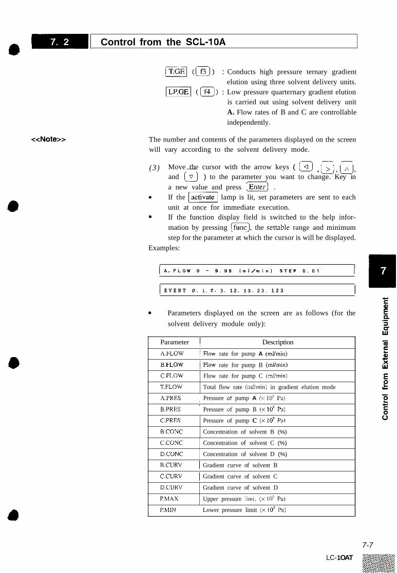
-1 Control from the SCL-1OA a
C.FLOW
T.FLOW
IT.GE] (() : Conducts high pressure ternary gradient
Flow rate for pump C (mllmin)
Total flow rate (mlhin) in gradient elution mode
elution using three solvent delivery units. (0) : Low pressure quarternary gradient elution
is carried out using solvent delivery unit A. Flow rates of B and C are controllable independently.
C.PRES
B.CONC
<<Note>>
Pressure of pump c (x lo5 Pa)
Concentration of solvent B (%)
The number and contents of the parameters displayed on the screen will vary according to the solvent delivery mode.
C.CONC
D.CONC
(3 ) Move - the cursor with the arrow keys ( , w, u,
Concentration of solvent C (%)
Concentration of solvent D (%)
and I.1 ) to the parameter you want to change. Key in a new value and press [Enter) . If the -1 lamp is lit, set parameters are sent to each unit at once for immediate execution.
D.CURV
P.MAX
0 If the function display field is switched to the help infor- mation by pressing (func), the settable range and minimum step for the parameter at which the cursor is will be displayed.
Examples:
Gradient curve of solvent D
Upper pressure limit (x 10’ Pa)
I E V E N T 0 . 1. 2 . 3. 1 2 . 1 3 . 2 3 . 1 2 3 I
Parameters displayed on the screen are as follows (for the solvent delivery module only):
Parameter 1 Description
A.FLOW I HOW rate for pump A (ml/min)
B.FLOW 1 mow rate for pump B (ml/min)
A.PRES I Pressure of pump A (x 105 Pa)
B.PRES I Pressure of pump B (x lo5 Pa)
B.CURV I Gradient curve of solvent B
C.CURV I Gradient curve of solvent C
P.MIN I Lower pressure limit (x 10’ Pa)
7-7
LC- 1 OAT

CI c
P =I v Lu
E .-
-1 Control from the SCL-1OA ‘ 6
5. Time Program When the setting of the initial parameters in the parameter control screen is complete, press (E) to return to the main menu screen and select I TIME PROGRAM 1 . From the time program screen, a time program, as described in Section 5.4 “Time Program Creation and Execution,” may be set through the SCL. In addition, program steps set in this time program editing screen can include parameters for other modules such as detectors.
Program entry I i nes
H Operation
T I M E P R O Q R A M F I L E 0 ( 8 . Q E )
3 0 0 S T E P S L E F T f l T I M E I F U N C I V A L U E
8 i 9 1
A I I I
F U N C T I O N F O R ( P U M P 0 E T . A D E T . B O T H E R ) 0 A . F L O W 1 5 8 . C O N C I 8 B . C U R V I 1 1 A . P R E S 1 B . F L O W 6 C . C O N C I 9 C . C U R V I 1 2 8 . P R E S 2 C . F L O W 1 7 O . C O N C I 1 0 O . C U R V 1 1 3 C . P R E S 4 T . F L O W 1 I I
T I M E I S T E P t i m e a f r c
9 9 9 9 . 9 0 / o 0 R E A D Y
Instruction table 3
(1) If a time program does not exist, the cursor is in the I TIME I field at step No. 0. First at, using the numeric keys, key in the desired time for the parameter you want to change. After keying in values, press (G) , then the cursor moves to the field.
0 I I
(2) (3)
Press (%) to select the function display that follows:
Use the v1 ( I) or r-1 ( Ifsl) key to move the highlighted box and select the module name in the FUNCTION FOR column.
F U N C T I O N F O R ( P V Y P . 1 D E T . A 0 E T . E O T H E R )
(4) The contents of the parameter table vary with the module name which is displayed in the FUNCTION FOR column. The following is the parameter table for I PUMP I
7-8 LC-1 OAT

-1 Control from the SCL-1OA a
<<Notes on Entry of program steps>>
5 B C O N C 8 B C U R V 1 1 A P R E S
7 D . C O N C I 1 0 0 . C U R V 1 3 C . P R E S 6 C : C O N C l 9 C : C U R V l 1 2 B : P R E S
I I
As for the parameters for another modules such as detectors, refer to the instruction manual of the SCL-IOA. (5 ) If you enter a number shown in the parameter table using
the numeric keys, the (func) field will show the number. By pressing (G) , the number disappears and the cor- responding parameter will appear. The parameter table is dis- played for ease of reference for parameter numbers. If a parameter has a number and it is not displayed on the screen, the entry of the value is possible anyway. If the selected parameter requires an argument (the entry of values), the cursor will move to the -1 field. Key in an appropriate value and press (G) . If you select the help information by pressing If...1 , the settable range and the minimum step of the argument required for the selected parameter will be displayed. If the parameter requires no argument, i.e., is a command, the cursor will move to the field of the next step. Repeat the procedures (2) to (6) above and complete the time program.
(6)
(7)
The time you enter in the -1 field must be equal to or later than that in the previous step. If you enter an earlier value, the alarm beeps when you press(=] and the entry is not accepted. (This is differnt than the time program editor of the LC- 1 OAT; See the SCL-1 OA manual for insfructions on how to insert steps into a time program, etc.)
(8) The following operation may be carried out from the time program screen using the function keys. By p r e s s i n g m , the function field switches and displays each function.
F l ( B ) The time program on the screen is output to the printer connected to the Chromatopac.
All the steps of the time program corresponding to the file number on the screen will be deleted.
- I ( @ )
7-9 LC- 1 OAT
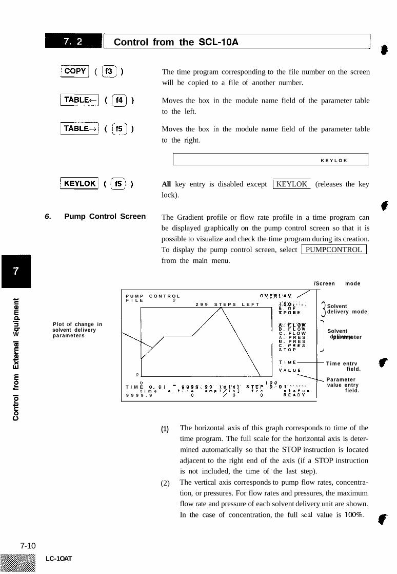
‘ l -1 Control from the SCL-1OA
6.
JCOPYI ( U)
/ I ( @ )
Pump Control Screen
4- S E P 3 v W
.- Plot of change in solvent delivery parameters
The time program corresponding to the file number on the screen will be copied to a file of another number.
Moves the box in the module name field of the parameter table to the left.
Moves the box in the module name field of the parameter table to the right.
K E Y L O K
All key entry is disabled except I KEYLOK I (releases the key lock).
c The Gradient profile or flow rate profile in a time program can be displayed graphically on the pump control screen so that it is possible to visualize and check the time program during its creation. To display the pump control screen, select I PUMPCONTROL I from the main menu.
/Screen mode
P U M P C O N T R O L F I L E 0
Solvent delivery mode 3 2 9 9 S T E P S L E F T >I T . L P . CIE Q E
Solvent C . F L O W A . P R E S parameter 6 . P R E S
delivery
T i m e entrv
Parameter value entry
field.
field. 0
0 T I M E 0 . 0 1 - 9 9
t i m e a f i l 9 9 9 9 . 9
(1) The horizontal axis of this graph corresponds to time of the time program. The full scale for the horizontal axis is deter- mined automatically so that the STOP instruction is located adjacent to the right end of the axis (if a STOP instruction is not included, the time of the last step). The vertical axis corresponds to pump flow rates, concentra- tion, or pressures. For flow rates and pressures, the maximum flow rate and pressure of each solvent delivery unit are shown. In the case of concentration, the full scal value is 100%.
(2)
@
7-10 LC-1 OAT
-1 Control from the SCL-1OA
(3) The solvent delivery mode field at the right shows the cur- rently selected mode in highlight. Below it, in addition, the functional parameter names for the solvent delivery modules in that mode are shown.
Operation (1) Press (funci to switch the function display as follows:
Select the desired solvent delivery mode with the function key. The selected solvent delivery mode is highlighted in the sol- vent delivery field at the upper right on the screen. Below it, parameter names corresponding to the mode are shown. By pressing function key -1 ( lfs) ), the highlighted box moves down one line in the parameter name field. Move it to the desired parameter name for setting. Below the -1 field, the cursor flashes. It is the same as (func) of the time program. Enter the desired time with the numeric keys and press[=). The entered time is displayed, and the cursor moves to the position below the field. It is the same as (TIME1 in the time program. Enter a parameter value with the numeric keys and press
The entered value is displayed and the cursor will move back to the [TIME] field. It is the same as the parameter value in the -1 field of the time program. If you set the solvent delivery mode to the high pressure gradient elution and selected VI in (3) for parameter name, proceed to (8). By the procedures from (3) to ( 5 ) the entry of 1 step in time programming is completed. Changes in flow rate (pressure) of the solvent delivery unit or concentration, which is caused by the entry of a new step, are displayed graphically on the screen. Complete the time program by repeating the entry procedures from step (3). By entering a parameter value for -1 with the numeric keys, the cursor moves further down by one step and flashes.
(Enter).
7-1 1 LC- 1 OAT

-1 Control from the SCL-1OA ‘ 6
Now enter the value for the shape of the gradient curve that starts from the current time. This is the value for the I CURV 1 parameter in time program- ming. If the value for the gradient curve is 0 (linear), just press
For the value and shape of the gradient curve, refer to the (Enter_).
instruction manual for the SCL- 1 OA. When the entry is complete, the screen returns to
0 10
The entry of steps does not need to be carried out according to the order of time. Each new step is inserted in the time program in the correct order by an automatic sort function. If you change solvent delivery mode from the pump control screen, the solvent delivery mode on the parameter control screen will also be changed. If a parameter for some other solvent delivery mode is entered while programming, it will be disregarded in the actual analysis. It is impossible to correct a wrong entry from this screen.
I p
In such a case, press (menu] to return to the main menu and correct the wrong entry with the editing function from the I TIME PROGRAM 1 screen.
Switching the Screen Mode -1: Information about all parameters listed at the right
of the screen are displayed on the screen at once. The plot line of one parameter (selected with the
The graphics display has two screen modes:
: -1 key) is displayed. -
Each time function key (-@ ) is pressed, the screen mode switches. The selected screen mode is highlighted at the right of the top line on the screen. CF
7-12 LC-1 OAT
a -1 Control from the SCL-1OA
The following operation is available using the function keys from the pump control screen.
IT.GE(O)
How rates for up to three solvent delivery units may be controlled independently.
Conducts high pressure binary gradient elution using two solvent delivery units (A, B). How rate for solvent delivery unit C is con- trolled independently.
Conducts high pressure ternary gradient elution using three solvent delivery units.
Low pressure quartemary gradient elution is carried out using sol- vent delivery A. Flow rates for unit B and C is controlled inde- pendently.
I I
Selects parameter name.
Switches the screen display mode.
All key entry is disabled except I KEYLOK I (releases the key lock). E
2 'c
7-13 LC- 1 OAT

Chapter 8 Maintenance
Contents
8.1 Replacement of Plunger Seals . . . . . . . . . . . . . . . . . . . . . . . . . . . . . . . . . . . . . 8-2
8.2 Replacement of Plungers . . . . . . . . . . . . . . . . . . . . . . . . . . . . . . . . . . . . . . . . . . 8-5
8.3 Replacement of Washing Seal ..................................... 8-7
Replacement of Line Filter ........................................ 8-10
Replacement of Fuse ............................................. 8-11
8.4 Cleaning and Replacement of Check Valves ......................... 8-9
8.5
8.6 8.7 Cleaning . . . . . . . . . . . . . . . . . . . . . . . . . . . . . . . . . . . . . . . . . . . . . . . . . . . . . . . . 8-12
8- 1 LC- 1 OAT

<<Caution>>
Replacement of Plunger Seals c
It is recommended that the plunger seal be replaced approx. every 2000 hours of solvent delivery. (Water delivery at ImVmin, 100 x lo5 Pa.) See MON REV in Section 5.5 “Auxiliary Functions (AUX.FUNC)”. When the plunger seal has been worn, the pressure becomes unstable, or solvent leaks from the gap between pump head and head holder or from the washing solution outlet. For replacement of the plunger seal follow the procedures below: (1) Assign 1 to the P.SET parameter. As for the setting method
of the P.SET parameter, see Section 5.5 (AUX.FUNC). The PUMP lamp will light up. Wait until this lamp goes off. Now the left and right plungers are set at the same position. Remove the SUS pipe and teflon tube which are provided at the upper right and lower left areas of the pump head, respectively.
(2)
(3)
f-
SUS pipe
Dismount it. e A Check valve OUT t?& Pump head
Check valve IN a Dismount it.
b‘---. Teflon tube
Fig. 8.1
When removing the suction filter, keep the top end of the suction filter tube at a position higher than the level of the solution in the reservoir, or empty the tube.
r - (4) Loosen the three screws which fix the pump head gradually
and alternately with the accessory Allen wrench. Then pull out the pump head.
Mounting screws Spring washers
Fig. 8.2
8-2
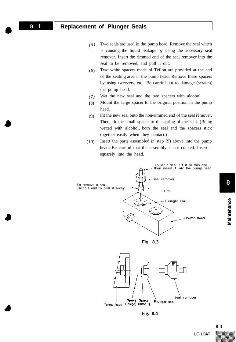
-1 Replacement of Plunger Seals a ( 5 ) Two seals are used in the pump head. Remove the seal which
is causing the liquid leakage by using the accessory seal remover. Insert the rimmed end of the seal remover into the seal to be removed, and pull it out. Two white spacers made of Teflon are provided at the end of the sealing area in the pump head. Remove these spacers by using tweezers, etc.. Be careful not to damage (scratch) the pump head. Wet the new seal and the two spacers with alcohol. Mount the large spacer to the original position in the pump head. Fit the new seal onto the non-rimmed end of the seal remover. Then, fit the small spacer to the spring of the seal. (Being wetted with alcohol, both the seal and the spacers stick together easily when they contact.) Insert the parts assembled in step (9) above into the pump head. Be careful that the assembly is not cocked. Insert it squarely into the head.
(6)
(7) (8)
(9)
(10)
To remove a use this end
sea I, to pul l it
To set a seal. f i t it to this end. then insert i t ' i n to the pump head.
Seal remover
r im. away.
Fig. 8.3
Fig. 8.4
8-3 LC- 1 OAT

‘ P -1 Replacement of Plunger Seals
(1 1) Mount the pump head as before and tighten the three screws alternately and uniformly. Finally, fit the short end of the hex wrench to each screw, grab the long handle and securely tighten each screw. Pay attention to the up/down orientation of the pump head. The left side has the check valve, while right side does not.
(12) Reconnect the tubing at the top and bottom of the pump head as before.
<<Caution>>
<<Note>>
It may take some time after replacing the plunger seal until solvent delivery become stable. Accordingly, carry out running for about an hour using the solvent of usual with a flow rate setting of 1 to 5mNmin and pressure of 30 to 100 x lo5 Pa before start of analysis.
f l
If only one seal leaks after both seals have been in service for some time, it is advisable to replace both since the undamaged seal will probably fail next, and possibly soon.
8-4
LC-1 OAT

Replacement of Plungers a
If leakage persists after replacement of the plunger seal or the ser- vice life of the new plunger seal is very short, the plunger surface may be damaged. Defects may be caused by foreign matter con- tained in the pump head or crystalline substances of the buffer solu- tion. In that case, the plungers need to be replaced. For replacement of the plungers, follow the procedures below:
(1)
(2)
Remove the pump head in the same manner as procedures (1) to (4) of Section 8.1 “Replacement of Plunger Seals.” Remove the seal holder assembly by pulling it out.
Seal holder assembly
Fig. 8.5
Release and remove the two screws on the left and right sides of the head holder with the accessory Allen. wrench. Then, release the two screws at the center alternately and gradually, and remove the head holder and the springs gently so that the head holder does not become cocked and jamb. Remove the plunger by turning it counterclockwise with the accessory wrench (13 x 17) as shown in Fig. 8.6. Mount the new plunger and fix it with the wrench.
8-5 LC- 1 OAT

-I( Replacement of Plunger ' F
/
e /
Fig. 8.6
Thoroughly wipe the plunger surface with a piece of soft cloth or tissue paper. Replace the head holder and spring to the original positions and tighten the two screws at the center alternately and uniformly until secure. Then securely tighten the two screws on the left and right. Clean the engaging section between the seal holder and head holder with a piece of soft cloth or tissue paper. Mount the seal holder to the original position. Mount the pump head as before and tighten the three screws alternately and uniformly. Fit the short end of the hex wrench to each screw and securely tighten them. Reconnect the tubing at the top and bottom of the pump head as before.
r -
8-6

Replacement of Washing Seal a
When the washing seal gets worn and washing solution leaks, the washing solution drips into the tray and is lead to the panel drain. If leakage of the solution is noticed, replace the washing seal.
\ t r a y
Fig. 8.7
U
Remove the pump head in the same manner as procedures (1) to (4) of Section 8.1 “Replacement of Plunger Seals.” Remove the seal holder by pulling it out.
ad holder
Seal holder
Fig. 8.8
8-7

-1 Replacement of Washing Seal ‘ 6
(3) Remove the washing seal from the seal holder in the same manner as the replacement of the plunger seal, using the seal remover. Slip a new seal over the non-rimmed end of the seal remover and push it vertically into the seal holder.
(4)
To set a seal, f i t i t to thls end, then insert i t in to the head
To remove a seal, use this end to pul l i t away.
I
Washing seal Seal holder
Fig. 8.9
( 5 ) Thoroughly wipe the engaging section between the seal holder and head holder with a soft cloth or a piece of tissue paper, then remount the seal holder gently without cocking it. Mount the pump head and tighten the three screws gradually and alternately with an equal torque. Reconnect tubing at the top and the bottom of the pump head as it was before.
(6)
(7)
F 8-8
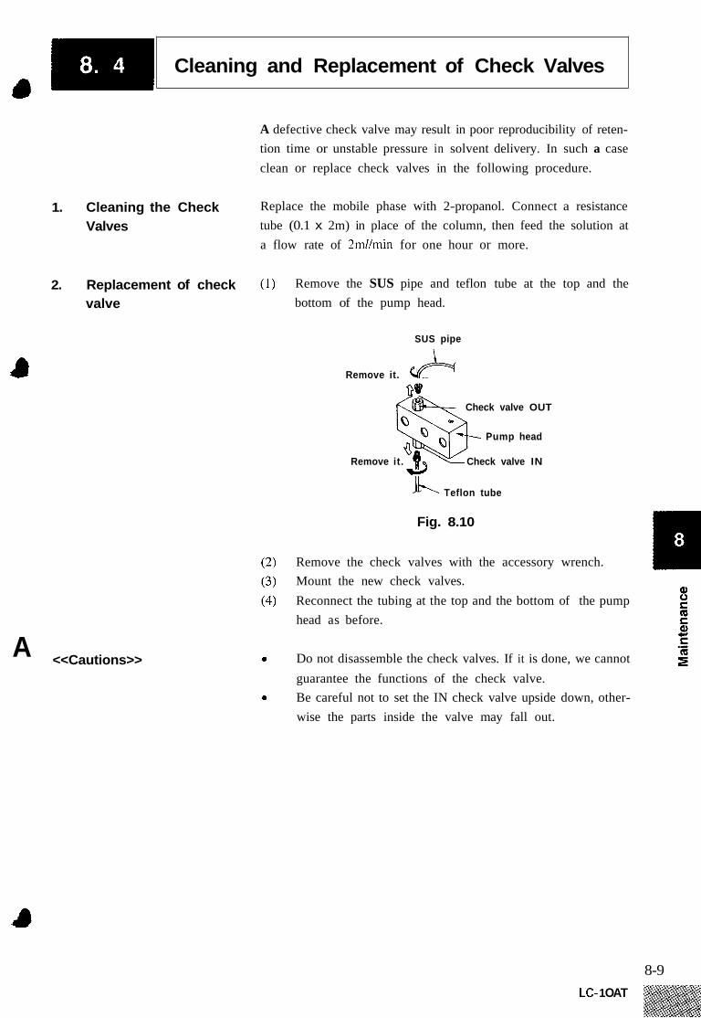
Cleaning and Replacement of Check Valves 4
A defective check valve may result in poor reproducibility of reten- tion time or unstable pressure in solvent delivery. In such a case clean or replace check valves in the following procedure.
1. Cleaning the Check Valves
2. Replacement of check valve
<<Cautions>> A
Replace the mobile phase with 2-propanol. Connect a resistance tube (0.1 x 2m) in place of the column, then feed the solution at a flow rate of 2mllmin for one hour or more.
Remove the SUS pipe and teflon tube at the top and the bottom of the pump head.
SUS pipe
Remove it. e A 09 <& Check valve OUT
Pump head
Remove it. Check valve IN
b-. Teflon tube
Fig. 8.10
Remove the check valves with the accessory wrench. Mount the new check valves. Reconnect the tubing at the top and the bottom of the pump head as before.
Do not disassemble the check valves. If it is done, we cannot guarantee the functions of the check valve. Be careful not to set the IN check valve upside down, other- wise the parts inside the valve may fall out.
8-9 LC- 1 OAT
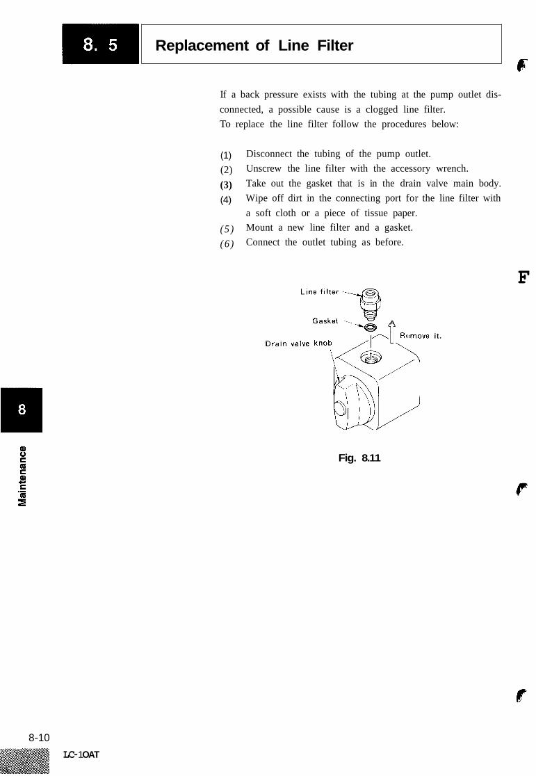
Replacement of Line Filter F
If a back pressure exists with the tubing at the pump outlet dis- connected, a possible cause is a clogged line filter. To replace the line filter follow the procedures below:
(1) (2) (3) (4)
Disconnect the tubing of the pump outlet. Unscrew the line filter with the accessory wrench. Take out the gasket that is in the drain valve main body. Wipe off dirt in the connecting port for the line filter with a soft cloth or a piece of tissue paper. Mount a new line filter and a gasket. Connect the outlet tubing as before.
( 5 ) (6 )
F
A
!move it .
Fig. 8.11
F
8-10 LC- 1 OAT
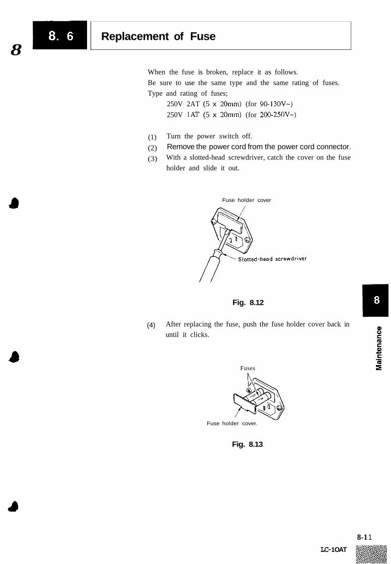
Replacement of Fuse 8
When the fuse is broken, replace it as follows. Be sure to use the same type and the same rating of fuses. Type and rating of fuses;
250V 2AT (5 x 20mm) (for 90-130V-) 250V 1AT (5 x 20mm) (for 200-250V-)
(1) (2) (3)
Turn the power switch off. Remove the power cord from the power cord connector. With a slotted-head screwdriver, catch the cover on the fuse holder and slide it out.
Fuse holder cover
Fig. 8.12
(4) After replacing the fuse, push the fuse holder cover back in until it clicks.
Fuses
Fuse holder cover.
Fig. 8.13
8-1 1
LC- 1 OAT

t CI t
~
Cleaning
If the cover or the front panel of the unit is dirtied, wipe away the dirt or dust with a soft cloth or a piece of tissue paper. If neces- sory, use a synthetic detergent.
E
f
8-12 LC-1 OAT

Chapter 9 Troubleshooting
Contents
9.1 Symptoms and Countermeasures for Troubles . . . . . . . . . . . . . . . . . . . . . . . . 9-2
9.2 Error Messages . . . . . . . . . . . . . . . . . . . . . . . . . . . . . . . . . . . . . . . . . . . . . . . . . . 9-3
m c .-
I-
9- 1 LC- 1 OAT

SvmDtoms and Countermeasures for Troubles I
Pump operation troubles result from various causes all of which cannot be covered in this manual. This section describes the troubleshooting measures on the basis of the symptoms. As for the countermeasures, detailed information is given in each relevant sec- tion.
Symptom Cause Remedy
I . Bubbles in the pump chamber. I . 2.
Flush liquid through the drain to purge bubbles. Suck up bubbles through the drain tubing with a syringe.
2. Old solvent remains in the pump chamber.
1. Increase flow rate and flush solvent through thc drair to purge the old mobile phase completely.
Increase the flow rate to purge the old solvent through the drain tubing.
1 .
2. Shake the suction filter to release bubbles. 3. If the suction filter is clogging, carry out ultrasonic
cleaning. If the ultrasonic cleaning is not effective. replace the suction filter.
4. Degas the mobile phase.
3. Bubbles in the suction filter enter the
pump. Solvent delivery is unstable. Fluctuation in pr- :ssure is large.
1. Clean or replace the check valves. 4. Malfunction of the check valves.
5. Leak from the plunger seal. I . Replace the plunger seal. 2. Replace the plunger.
I . 2. Replacement of defective parts.
'lighten the joints in the flow line. 6. Leak in the flow line.
7. Flow line clogged 1. 2. Check the flow line.
Clean or replace the line filter.
The pump opera- .es but solvent is lot delivered.
I . Bubbles in the pump chamber. 1. 2.
Flush liquid through the drain to purge bubbles. Suck up bubbles through the drain tubing with a syringc.
2. Air enters from the joint between the suction filter and inlet pipe.
1. Firmly connect the joint. ~~~~~ ~
I . Malfunction of the check valves. 1.
1.
Clean or replace the check valves.
Clean or replace the suction tilter.
Measured flow -ate is lower than .he set flow rate. 2. Clogged suction filter.
Solvent is not de- livered. :Pump is not op- :rating.)
Pressure does not ise.
1. An error message is displayed. (P.MAX, P.MIN, etc.)
I . Press .
Remove the cause of the error.
1. Close the drain valve. I . The drain valve is open.
2. Leakage in flow line. 1. Tighten joints. 2. Replacement of defective parts.
1. Clean line filter. 2. Replace line filter.
Pressure rises ex- zessivel y. :Confirm i t by -emoving the co- unin.)
1 . Line filter clogged
1. Identify the clogged component and replace it. 2. Flow line clogged
3. The inside diameter of tubing is excessively small.
1. Replace thc tubing with another having an appropriatc inside diameter.
9-2 LC-1 OAT

Error Messages 4
This unit has multiple self-diagnostic testing functions, which beep an alarm and show an error message if they detect any abnor- malities. Except for the case (1 ) and (2), pressing a will stop the alarm beep and return the display to the initial screen.
1. ROM Error
2. RAM Error
3. Lost RAM File Error
4. Overstepping Error
I R O M F A I L U R E
This error message will be displayed when there is something ir- regular in the ROM. If this error message is displayed, pressing ICE) will not release the system from the error. Turn off the power source for the unit, and contact our office or agent .
R A M F A I L U R E
This error message will be displayed when there is something ir- regular in the RAM. If this error message is displayed, pressing CE Turn off the power source for the module, and contact our office or agent.
will not release the system from the error.
[ N O T P R O T E C T E D 1 This error message will be displayed when the contents of the RAM have been lost or destroyed due to power source abnormalities. By pressing a , the module may become operable. However, if this error message is displayed every time the power switch is turned on, the problem may be caused by dead or low power backup batteries. Contact our office or agent for information on exchanging the backup batteries.
This error message is displayed when the total number of steps used in the time programs exceeds 320. If this error message is displayed, the time program can not be prepared any further. Continue entering program data after deleting unnecessary files.
9-3 LC- 1 OAT

-1 Error Messages 16 5. Maximum Pressure Error
E R R O R P- M A X
6. Minimum Pressure Error
7. Home Position Error
8. Purge Error
This error message will be displayed when the upper limit pressure, p-max, has been exceeded by the actual delivery pressure. In this case solvent delivery stops. (However, if S.PROT function is ac- tivated, the unit only reduces the flow rate by one half without stopping the pump.) When this error message is displayed, check the flow line for clogging, and if there is no problem, set the P-MAX value to an appropriate value.
E R R O R P - M I N 1 d
This error message will be displayed if the actual delivery pressure is less than lower limit pressure P.MIN after 1 min. of operation. In this case the limiter stop the solvent delivery. If this error occurs, check the flow line for leakage, and if there is no problem, set the p.min value to an appropriate value. This error trapping will not function in the first one minute after the start of the solvent delivery in order to allow for pressure equilibration when just begin- ning to pump.
[ E R R O R H O M E P O S
This error message is displayed when the home position of the motor can not be detected. It is also displayed when the motor slips. In this case, press the ICE) key to cancel the error, then press
(pump) to operate. If the same error appears again, turn off the power for the unit, then turn it on again after 10 or 15 seconds and try it again. If this doesh’t work, contact our office or agent.
O P E N D R A I N V A L V E 1 This error message is displayed if the actual delivery pressure of the pump exceeds 5kgf/cm2 during purge operations started with the (purge) key. The (CE) key will release the system from the error. Start the purge operation again after opening the drain valve. If the error message is displayed even with the drain valve open, execute the zero adjustment of the pressure sensor (see ZERO ADJ in 5.5 “AUX.FUNC”).
I
f
9-4 LC-1 OAT

Chapter 10 Specifications
Contents
10.1
10.2 High Pressure Gradient Elution Specifications ........................ 10-3
10.3 Low Pressure Gradient Elution Specifications ....................... 10-4
LC-IOAT Unit Specifications . . . . . . . . . . . . . . . . . . . . . . . . . . . . . . . . . . . . . . 10-2
10-1

LC-1OAT Unit Specifications (R
1. Pump type A 2-stage (tandem-flow) double-plunger reciprocating pump.
2. Modes of solvent delivery Constant flow or constant pressure solvent delivery 2.1 Constant flow delivery
0.001 - ~ m ~ m i n (10 - 400 [x 10’ pa]) 5.001 - 9.99mNmin (10 - 200 [ X lo5 Pa]) Within +2% or +2pl/min of set value, whichever is higher (0.1 - SmUmin, 10 - 400 [x 10’ Pa], with water and room tempera- ture at 20°C )
Within *.3% (0.1 - Smlmin, I0 - 400 [x lo5 Pa] with water and room temperature at 2OOC)
Flow rate range:
0 Flow rate accuracy:
0 Flow rate precision:
2.2 Constant pressure delivery
3.
4.
5.
6.
7.
8.
9.
10.
11.
12.
13.
Pressure setting
.Pressure setting range: 10 - 400 [x lo5 Pa] (in 1 [x 10’ Pa] steps)
Within +lo% or k10 [x lo5 Pa] of set value, whichever is larger
User-settable HighLow pressure limits
accuracy:
Pressure limits:
Materials in contact with solvent: SUS3 16, UHMW-PE, Elgiloy@, Kalrez@, PEEK
ETFE, PCTFE, PTFE
Suction filter: lOpm mesh
Line filter:
Time program:
2pm mesh, liquid volume approx. 2OOpl
Flow rate, pressure, EVENT, LOOP (program repeat), 10 files, total 320 steps I1F
Pressure indication accuracy:
Plunger cleaning flow line: Built-ing Cleaning of plunger seals is possible with the connection
Within +2% or +5 [x lo5 Pa], whichever is larger
of syringe or pump.
260W x 140H x 420D (except protruding components) Size:
Weight: l lkg
0 perati n g tem peratu re I
range: 5 - 35°C I
Power requirements: (Power requirements vary depending upon the line voltage.) P/N 228-3 1900-91, 92: 90-1 30V- 50/60Hz 1 OOVA 6“1 P/N 228-3 1900-93. : 200-25OV- 50/60H~ 1 00VA
10-2 LC-1 OAT
High Pressure Gradient Elution Specifications 4
1. LC-1OAT Control - High Pressure Gradient Elution Specifications
1) Number of solvents: 2
2) Gradient profile: Stepwise and linear, multiple processes are possible in a single pro- gram.
3) Number of program files: 10 files with a total of 320 program steps
4) Program mable time: 0.01 min - 999.99 min, 0.01 min steps
5) Settable Concentration range: 0 - loo%, 0.1% steps 4
6) Concentration setting 51% (0 - loo%, 0.3 - 3ml/min, 10 - 400 [x 10’ Pa], with aqueous accuracy: ace tone/water)
2. SCL-lOA Control - High Pressure Gradient Elution Specifications
1) Number of solvents: 2 or 3
2) Gradient profiles: Stepwise, linear, and exponential functions, multiple processes are possible in a single program.
3) Number of program files: 20 files, with a total of 400 program steps
4) Programmable time: 0.01 min - 9999.9 min, 0.01 min steps
5) Settable Concentration range: 0 - loo%, 0.1% steps
6) Concentration setting accuracy: + I % (0 - loo%, 0.3 - 3ml/min, 10 - 400 [x 10’ Pa], with aqueous
acetonejwater)
10-3 LC- 1 OAT

Low Pressure Gradient Elution Specifications c
I. LC-IOAT Control - Low Pressure Gradient Elution Specifications
Number of solvents mixed: up to 4
Stepwise and Linear, multiple processes are possible in a single program.
Gradient profiles:
Number of program files: a total of 10 files and 320 steps
0.01 - 999.99 min, 0.01 min steps Programmable time:
Settable Mixing ratio range: 0 - loo%, 0.1% steps
f 2% Concentration accuracy
Flow rate range 0.1 - 2mUmin (In the case of a flow rate of more than 2 mllmin, the life time of the valves of the low pressure gradient unit become short due to high speed cycling.)
2. SCL-1OA Control - Low Pressure Gradient Elution Specifications
Number of solvents mixed: up to 4
Gradient profiles: Stepwise, linear and exponential functions; multiple processes are prossible in a single program.
Number of program files: a total of 20 files and 300 steps
0.01 - 9999.9 min Programmable time:
Mixing ratio setting range: 0 - loo%, 0.1% steps
Concentration accuracy f 2%
7) Flow rate range 0.1 - 2mUmin (In the case of a flow rate of more than 2 mllmin, the life time of the valves of the low pressure gradient unit become short due to high speed cycling.)
10-4 LC-1 OAT

I
Contents
Chapter I1 Spare Parts and
11.1
11.2
11.3
Consumable Parts List . . . . . . . . . . . . . . . . . . . . . . . . . . . . . . . . . . . . . . . . . . . . 11-2
List of Other Necessary Parts . . . . . . . . . . . . . . . . . . . . . . . . . . . . . . . . . . . . . 11-3
Optional Units List . . . . . . . . . . . . . . . . . . . . . . . . . . . . . . . . . . . . . . . . . . . . . . 11-4
11-1

Consumable Parts List ~
I I Part name I Part number I Remarks I I I I I Plunger seal (yellow) I 228-21975 I Seal for pump head
11-2 LC-1 OAT
%;& .

List of Other Necessary Parts .II)
Part name
1 PB-I assy ROM included 2 PB-I assy ROM not included
4 Fuse IAT 5 x 20 5 Fuse 2AT 5 x 20
3 ROM LC-IOAT
1. Mechanical Parts
Part number Remarks
228-24785-95 ROM included 228-23685-93
072-0 1652- 16 For 200V 072-01652-19 For l00V
ROM not included (Photocoupler included) 228-24783-95
1 2 3 4 5 6 7 8
9 10 11 12 13 14
Part name ~~~ ~~ ~
Plunger assy Head holder Seal PE (white) Pump head Check valve OUT Check valve IN Pressure sensor assy Filter assy standard
Gasket Suction filter assy Photosensor assy Drain valve shaft IOAS ASSY Spacer (large) Spacer (small)
for Low Pressure Gradient
Part number
228-32654-9 1 228-3 1903 228-28499 228-3 1905 228-3253 1-92 228-32166-91 228-32252-92 228- 12642-93
(228-32467-9 1)
228-1 8740-9 1 228-1 2564
228-28288-9 1 228-2831 2-92 228-32325-01 228-3240 1
Remarks
Seal for washing solution
Including line filter and drain valve
Low volume type 3228- 32 6 93 - For line filter replacement
For detection of the home position of pump
, > For plunger seal
11-3 LC- 1 OAT
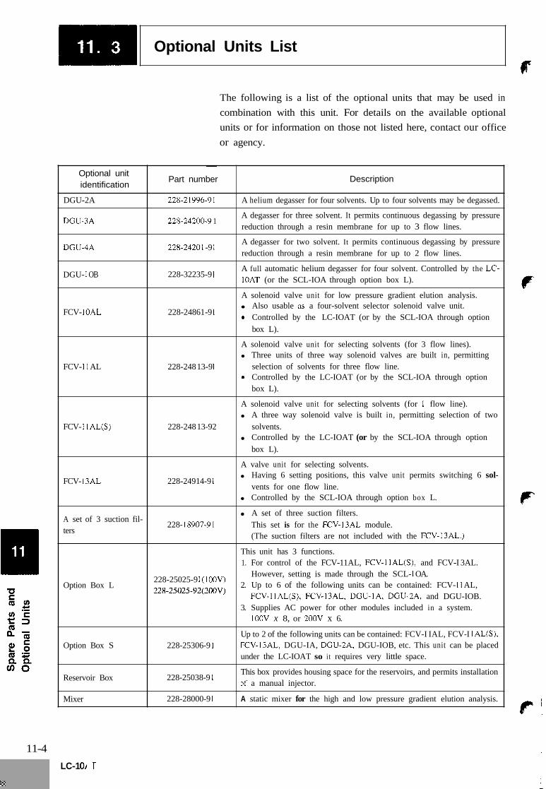
Optional Units List r
The following is a list of the optional units that may be used in combination with this unit. For details on the available optional units or for information on those not listed here, contact our office or agency.
~
Part number Description Optional unit identification
~ ~
A helium degasser for four solvents. Up to four solvents may be degassed. 228-21996-91 DGU-2A
DGU3A 228-24200-9 1 A degasser for three solvent. It permits continuous degassing by pressure reduction through a resin membrane for up to 3 flow lines.
DCU-4A 228-24201 -9 1 A degasser for two solvent. It permits continuous degassing by pressure reduction through a resin membrane for up to 2 flow lines.
DGU- 1 OB 228-32235-9 1 A full automatic helium degasser for four solvent. Controlled by the LC- IOAT (or the SCL-IOA through option box L).
A solenoid valve unit for low pressure gradient elution analysis. Also usable as a four-solvent selector solenoid valve unit.
0 Controlled by the LC-IOAT (or by the SCL-IOA through option box L).
FCV- IOAL 228-24861 -9 1
A solenoid valve unit for selecting solvents (for 3 flow lines). Three units of three way solenoid valves are built in, permitting selection of solvents for three flow line.
0 Controlled by the LC-IOAT (or by the SCL-IOA through option box L).
FCV- 1 1 AL 228-248 13-9 1
A solenoid valve unit for selecting solvents (for 1 flow line). A three way solenoid valve is built in, permitting selection of two solvents. Controlled by the LC-IOAT (or by the SCL-IOA through option box L).
FCV- 1 1 AL(S) 228-248 13-92
A valve unit for selecting solvents. Having 6 setting positions, this valve unit permits switching 6 sol- vents for one flow line. Controlled by the SCL-IOA through option box L.
FCV- 13AL 228-2491 4-9 1
~~ ~
A set of three suction filters. This set is for the FCV-l3AL module. (The suction filters are not included with the FCV-13AL.)
A set of 3 suction fil- ters
228- 18907-9 I
This unit has 3 functions. 1. For control of the FCV-11 AL, FCV-1 IAL(S), and FCV-I 3AL.
However, setting is made through the SCL- 1 OA. 2. Up to 6 of the following units can be contained: FCV- I 1 AL,
FCV-IIAL(S), FCV-I3AL, DGU-lA, DGU-2A, and DGU-IOB. 3. Supplies AC power for other modules included in a system.
lOOV x 8, or 2OOV x 6.
228-25025-9 1 (1 OOV) 228-25025-92(2OOV)
Option Box L
Up to 2 of the following units can be contained: FCV-I IAL, FCV-I IAL(S), FCV-I3AL, DGU-IA, DGU-2A, DGU-IOB, etc. This unit can be placed under the LC-IOAT so i t requires very little space.
228-25306-9 1 Option Box S
Reservoir Box 228-25038-9 1 This box provides housing space for the reservoirs, and permits installation D f a manual injector.
A static mixer for the high and low pressure gradient elution analysis. Mixer 228-28000-9 1
11-4 LC-1 OAT
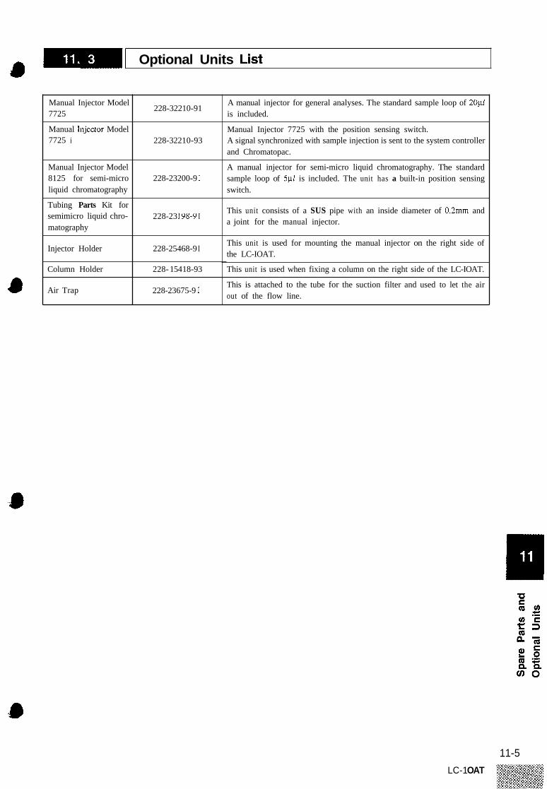
-1 Optional Units List 4 Manual Injector Model 7725
Manual Injedor Model 7725 i
Manual Injector Model 8125 for semi-micro liquid chromatography
Tubing Parts Kit for semimicro liquid chro- matography
Injector Holder
Column Holder
Air Trap
228-32210-91
228-3221 0-93
228-23200-9 1
228-23 198-9 I
228-25468-9 I
228- 154 18-93
228-23675-9 1
A manual injector for general analyses. The standard sample loop of 20p1 is included.
Manual Injector 7725 with the position sensing switch. A signal synchronized with sample injection is sent to the system controller and Chromatopac.
A manual injector for semi-micro liquid chromatography. The standard sample loop of 5yl is included. The unit has a built-in position sensing switch.
This unit consists of a SUS pipe with an inside diameter of 0.2mm and a joint for the manual injector.
This unit is used for mounting the manual injector on the right side of the LC-IOAT.
This unit is used when fixing a column on the right side of the LC-IOAT.
This is attached to the tube for the suction filter and used to let the air out of the flow line.
11-5 LC-1 OAT

8
Chapter 12 Reference Material
a
12.1 Precautions on Static Electricity . . . . . . . . . . . . . . . . . . . . . . . . . . . . . . . . . . . 12-2
12.2 Mobile Phase Characteristics . . . . . . . . . . . . . . . . . . . . . . . . . . . . . . . . . . . . . . 12-6
t a
12-1

Chapter 12 Reference Material
a
12.1 Precautions on Static Electricity . . . . . . . . . . . . . . . . . . . . . . . . . . . . . . . . . . . 12-2
12.2 Mobile Phase Characteristics . . . . . . . . . . . . . . . . . . . . . . . . . . . . . . . . . . . . . . 12-6
12-1
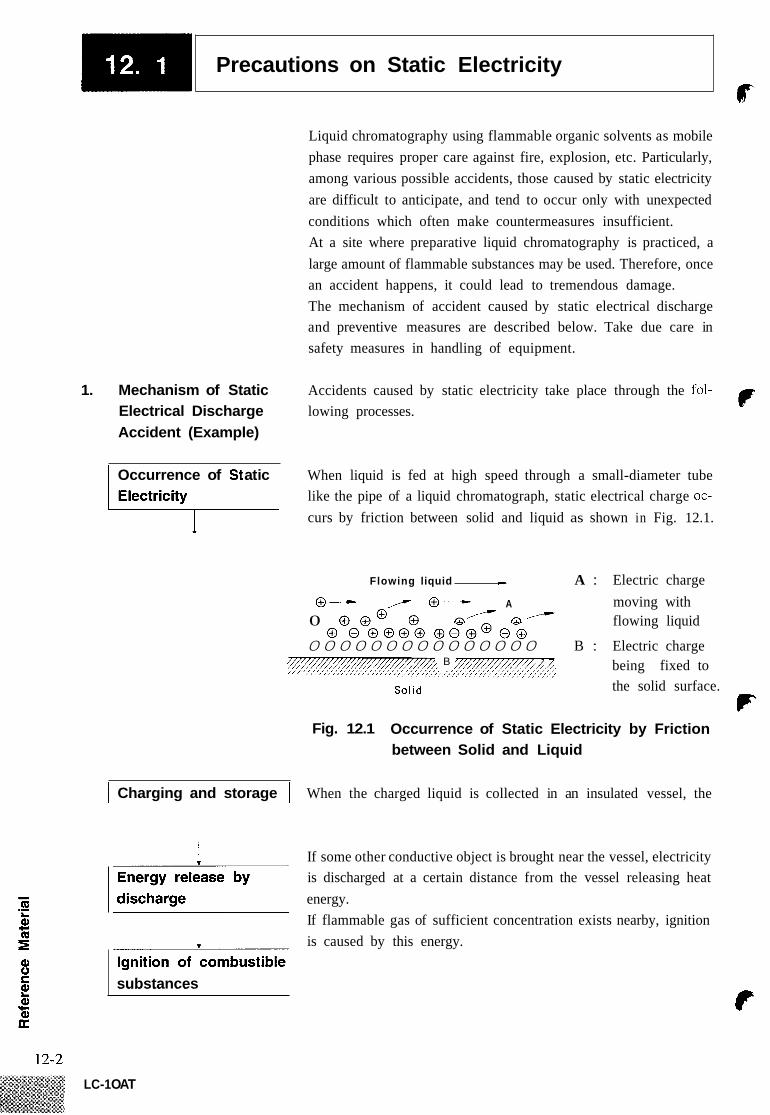
Precautions on Static Electricity r
Liquid chromatography using flammable organic solvents as mobile phase requires proper care against fire, explosion, etc. Particularly, among various possible accidents, those caused by static electricity are difficult to anticipate, and tend to occur only with unexpected conditions which often make countermeasures insufficient. At a site where preparative liquid chromatography is practiced, a large amount of flammable substances may be used. Therefore, once an accident happens, it could lead to tremendous damage. The mechanism of accident caused by static electrical discharge and preventive measures are described below. Take due care in safety measures in handling of equipment.
F 1. Mechanism of Static Accidents caused by static electricity take place through the fol- Electrical Discharge lowing processes. Accident (Example)
Occurrence of St at i c When liquid is fed at high speed through a small-diameter tube like the pipe of a liquid chromatograph, static electrical charge oc- curs by friction between solid and liquid as shown in Fig. 12.1.
Flowing liquid c A : Electric charge 0- ,--- 0- A moving with
0 @ @ @ @ @/ @ / flowing liquid
000000000000000 B : Electric charge 0 GO@@@ @0@@0@ -=/,- B
Solid
being fixed to the solid surface.
F Fig. 12.1 Occurrence of Static Electricity by Friction
between Solid and Liquid
I Charging and storage I When the charged liquid is collected in an insulated vessel, the
If some other conductive object is brought near the vessel, electricity is discharged at a certain distance from the vessel releasing heat energy. If flammable gas of sufficient concentration exists nearby, ignition is caused by this energy.
substances
LC-1 OAT

-1 Precautions on Static Electricity ‘9
iqu id i s f l ow ing at a h igh speed through a smal l - diameter tube.
lated if bubbles are included i n the l iquid.
*Charge is easily accumu-
Insulated vessel ( l ike polyethylene)
F lammable gas is stored in the head space of the
Spark discharge
Spark discharge
ammable organic solvent charged to a great extent.
--Wr Floor covered w i th .rubber, etc., - - f- provides unwanted insulat ion.
Fig. 12.2 Conditions for Accidents
2. Preventive Measures The principal preventive measure is the prevention of “charging and storage of static electricity” among those items shown in “Oc- currence mechanism of static electrical discharge accidents.” The preventive measures are shown below. It is recommended to ex- ercise two or more measures simultaneously.
Particularly when a large quantity of flammable solvent is held in a large vessel, be sure to observe the preventive measures 1, 2, and 3.
against Accidents
9i
Preventive measure 1. Use metallic (conductive) waste liquid vessel which is well grounded. This releases the charge of the waste liquid and vessel to ground. The following items are available. (1) Grounding wire with clip P/N 228-21353-91 (2) Metallic 18 liter can P/N 038-00044 (3) Metallic 4 liter can P/N 038-00043-01 ... X: Be sure to ground the vessel properly. Disconnecting of
grounding wire or poor grounding defeat the purpose of using - Q
a metallic vessel. .- 9i There are some metallic cans which have no conductivity
sure to confirm the grounding of vessels by a tester before application. c
When a liquid with almost no conductivity (of 10-”s/m or less) is discharged into the vessel, it is necessary to mix it
t CI z due to an oxidized coating or lacquer on their surface. Be Q1 0
9i Ic f QI U
12-3 LC- 1 OAT

I Precautions on Static Electricity Qp
with another liquid with some conductivity. (The other liquid can be placed in the vessel in advance.)
Preventive measure 2. Minimize the clearance of both inlet and outlet of vessel to prevent flame from entering the vessel. (1) Cap with three holes for 18 liter and 4 liter cans (P/N 228-
2 1354-91) is available.
Connect c l i p to metal l ic pa r t I /
Connect t o the grounding terminal of the device to ground the meta l l lc vessel. (c" by attaching a cap.
Min imize clearance
Metal l ic 18 l i te r can (A plated can is recommended.)
-Static electricity of the l i qu id is released via vessel.
Fig. 12.3 Anti-Static Electricity Measures for Vessel
Preventive measure 3. Do not approach the vessel with charged objects including the human body. Charging prevention measures for human body
a) b) Grounding of human body c) Make working floor conductive
Prevention of charging of shoes and clothes
Suitable products to be used for those measures a), b), and c) are available on the market.
When persons who use no charge prevention measures ap- proach dangerous sections, they have to be grounded beforehand. (For example, they should contact grounded metal by hand.)
%
Preventive measure 4. Use pipes with inner diameter of 2mm or more for waste liquid line for large flow rates.
Inclusion of bubbles in the tube may increase the amount of charging by ten times. Check that there is no inclusion
%
of air via tube joints.
F 12-4
LC-1 OAT

1 Precautions on Static Electricity
Preventive measure 5. When it is impossible to use a conductive vessel, use caution in the following points.
Set the vessel so that the pipe outlet will be placed below the liquid level in the vessel. Or, dip a grounded metal (ex. pipe connected to the main body of device) in the liquid. This method is not effective for liquid with small conductivity (lO-'Os/m or less). Use a vessel of the smallest possible capacity to minimize the damage by fire if it should occur. Prevent the room from being dry. Humidity of 65% or more has charge prevention effects.
a)
%
b)
c)
12-5 LC- 1 OAT
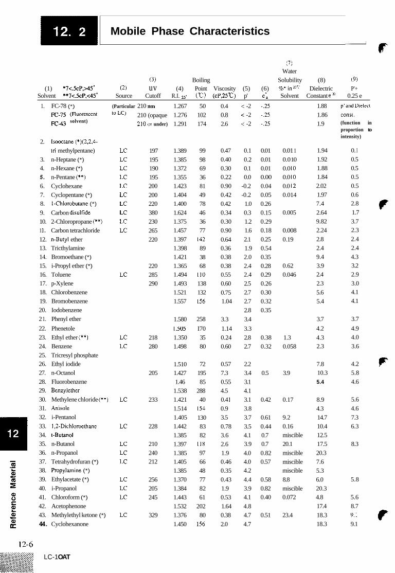
Mobile Phase Characteristics ~
(7) Water
(3) Boiling Solubility (8) (9) (1) *7<.5cP,>45' (2) uv (4) Point Viscosity (5) (6) %" inZoC Dielectric P'+
Solvent **7<.5cP,<45' Source Cutoff R.I. 25. ("c) (cP.25"C) p' e: Solvent Constant e m 0.25 e
1. FC-78 (*) (Particular 210 nm
Fc43 solvent)
2. Isooctane (*)(2.2,4-
3. n-Heptane (*) 4. n-Hexane (*) 5 . n-Pentane (**) 6. Cyclohexane 7. Cyclopentane (*) 8. 1Chlorobutane (*) 9. Carbon disulfide 10. 2-Chloropropane (**) 1 I . Carbon tetrachloride 12. n-Butyl ether 13. Tricthylamine 14. Bromoethane (*) 15. i-Propyl ether (*) 16. Toluene 17. p-Xylene 18. Chlorobenzene 19. Bromobenzene 20. Iodobenzene 2 1. Phenyl ether 22. Phenetole 23. Ethyl ether (**) 24. Benzene 25. Tricresyl phosphate 26. Ethyl iodide 27. n-Octanol 28. Fluorobenzene 29. Benzylether 30. Methylene chloride (**) 31. Anisole 32. i-Pentanol 33. 1,2-Dichloroethane
35. n-Butanol 36. n-Propanol 37. Tetrahydrofuran (*) 38. Propylamine (*) 39. Ethylacetate (*) 40. i-Propanol 41. Chloroform (*) 42. Acetophenone 43. Methylethyl ketone (*) 44. Cyclohexanone
tri methylpentane)
34. t-Butanol
LC LC LC LC LC LC LC LC LC LC
LC
LC LC
LC
LC
LC LC LC
LC LC LC
LC
210 (opaque 210.or under)
197 195 190 195 200 200 220 380 230 265 220
220 285 290
218 280
205
233
228
210 240 212
256 205 245
329
1.267 1.276 1.291
1.389 1.385 1.372 1.355 1.423 1.404 1.400 1.624 1.375 1.457 1.397 1.398 1.421 1.365 1.494 1.493 1.521 1.557
1.580 1 SO5 1.350 1.498
1.510 1.427 1.46
1.538 1.421 1.5 14 1.405 1.442 1.385 1.397 1.385 1.405 1.385 1.370 1.384 1.443 1.532 1.376 1.450
50 102 174
99 98 69 36 81 49 78 46 36 77
142 89 38 68
110 138 132 156
258 I70 35 80
72 195 85
288 40
154 130 83 82
118 97 66 48 77 82 61
202 80
156
0.4 0.8 2.6
0.47 0.40 0.30 0.22 0.90 0.42 0.42 0.34 0.30 0.90 0.64 0.36 0.38 0.38 0.55 0.60 0.75 1.04
3.3 1.14 0.24 0.60
0.57 7.3 0.55 4.5 0.4 1 0.9 3.5 0.78 3.6 2.6 1.9 0.46 0.35 0.43 1.9 0.53 1.64 0.38 2.0
< -2 -.25 < -2 -.25 < -2 -.25
0.1 0.01 0.2 0.01 0.1 0.01 0.0 0.00
-0.2 0.04 -0.2 0.05 1.0 0.26 0.3 0.15 1.2 0.29 1.6 0.18 2.1 0.25 1.9 0.54 2.0 0.35 2.4 0.28 2.4 0.29 2.5 0.26 2.7 0.30 2.7 0.32 2.8 0.35 3.4 3.3 2.8 0.38 2.7 0.32
2.2 3.4 0.5 3.1 4.1 3.1 0.42 3.8 3.7 0.61 3.5 0.44 4.1 0.7 3.9 0.7 4.0 0.82 4.0 0.57 4.2 4.4 0.58 3.9 0.82 4.1 0.40 4.8 4.7 0.51 4.7
0.01 1 0.0 10 0.0 10 0.0 10 0.0 I2 0.014
0.005
0.008 0.19
0.62 0.046
1.3 0.058
3.9
0.17
9.2 0.16 miscible 20.1 miscible miscible miscible 8.8 miscible 0.072
23.4
1.88 1.86 1.9
1.94 1.92 1.88 1.84 2.02 1.97 7.4 2.64 9.82 2.24 2.8 2.4 9.4 3.9 2.4 2.3 5.6 5.4
3.7 4.2 4.3 2.3
7.8 10.3 5.4
8.9 4.3 14.7 10.4 12.5 17.5 20.3 7.6 5.3 6.0 20.3 4.8 17.4 18.3 18.3
p'and Dielect.
const. (function in proportion to intensity)
0. I 0.5 0.5 0.5 0.5 0.6 2.8 f 1.7 3.7 2.3 2.4 2.4 4.3 3.2 2.9 3.0 4.1 4.1
3.7 4.9 4.0 3.6
4.2 F 5.8 4.6
5.6 4.6 7.3 6.3
8.3
5.8
5.6 8.7
9.1 c 9.1
LC-1 OAT

1 Mobile Phase Characteristics 0
(7) Water
Solubility (8) (9) (6) %" in mr Dielectric P'+ e: Solvent Constantem 0.25 e
34.8 13.2 25.2 10.9
miscible 2.2 0.56 23.0 10.7
9.0 7.4 miscible 12.4 0.9
0.71 miscible 13.1 8.8
0.6 miscible 19.9
0.56
miscible 24.6
6.9 miscible 6.2 miscible 37.5
0.88 37.8
(3) uv
Cutoff
Boiling (4) Point Viscosity (5)
R.I. 25* ("c) (cP.25"c) p' ( 1 ) *7<.5cP,>45'
Solvent **7<.5cP,c45' (2)
Source
45. Nitrobenzene 46. Benzonitrile 47. Dioxane 48. Tetramethyl urea 49. Quinoline 50. Pyridine 5 I . Nitroethane 52. Acetone (*) 53. Benzyl alcohol
1.550 1.536 1.420 1.449 1.625 1.507 1.390 1.356 1.538
211 1.8 4.4 191 1.2 4.8 101 1.2 4.8 175 6.0 237 3.4 5.0 115 0.88 5.3 114 0.64 5.2 56 0.30 5.1
205 5.5 5.7 6.1
125 1.60 5.5
LC LC
215 265
380 330 LC
54. Tetramethyl guanidine
56. Tris (cyanoethoxy) 55. Methoxyethanol LC 210 1.400
propane 57. Propylene carbonate 58. Ethanol 59. Oxydipropionitrile 60. Aniline 61. Acetic acid 62. Acetonitrile (*)
63. N, N-dimethylaceta-
64. Dimethylformamide 65. Dimethylsulfoxide 66. N-methyl-2-pyrolidone 67. Hexamethyl phosphoric
68. Methanol (*)
mide
acid triamide
GC LC LC GC
6.6 6.1
1.359 78 1.08 4.3 6.8
1.584 184 3.77 6.3 1.370 118 1 . 1 6.0 1.341 82 0.34 5.8 1.436 166 0.78 6.5
210
8.1
LC LC
190 268
LC LC LC
268 268 285
1.428 153 0.80 6.4 36.7 1.477 189 2.00 7.2 0.62 miscible 4.7 1.468 202 1.67 6.7 32
I .457 1.326 1.380 1.540 1.447 1.431 1.447 1.333
233 3 7.4 65 0.54 5.1
101 0.61 6.0 202 14 7.4 182 1.65 6.0 182 16.5 6.9 210 3.3 9.6 100 0.89 10.2
Q.65 30 miscible 32.7 2.1
11.8 miscible 182 miscible 37.7 miscible 11 1
80
LC 205 380 69. Nitromethane
70. m-Cresol 10.0 7 1. N-methylformamide 72. Ethylene glycol 73. Formamide 74. Water LC
Q 0 C Q
12-7 LC-1 OAT

‘ c -1 Mobile Phase Characteristics
12-8
(*) indicates solvents most suitable for LC, having convenient boiling points (A5”C) and low viscosity ( 1 0 . 5 ~ ~ ) . (”*) indicates solvents with very low viscosity and boiling point. “LC” indicates that the solvents are commercially available specifically for LC from the following companies: Burdick & Jackson, Baker Chemical, Mallinkrodt Chemical, Fischer Scientific, Waters Associates and Manufacturing Chemists, Inc. (Note: In Japan, they are also commercially available from the following companies: Wako Pharmaceutical Co., Ltd., Nakarai Pharmaceutical Co., Ltd. and Kanto Chemical Co., Ltd.) “GC” indicates that the solvent is used as a stationary phase for gas chromatography, and can be purchased from com- panies selling GC columns and stationary phases. (These sol- vents are used as a stationary phase in the liquid-to-liquid LC.) The wavelength shorter than which the solvent becomes opa- que. Refractive index at 25°C Polarity parameter of solvent Solvent strength parameter of liquid-to-solid adsorption on alumina Water solubility (W%) at 20°C for solvent used in liquid- to-solid adsorption Value at 20°C
6
Function where P’ is proportional to solvent strength and CF dielectric constant in ion pair chromatography.
LC-1 OAT


