Some Broad-Band Transformers" C. L. RUTHROFFt, MEMBER, IRE Summary-Several transmission line transformers are described which have bandwidth ratios as high as 20,000: 1 in the frequency range of a few tens of kilocycles to over a thousand megacycles. Experimental data are presented on both transformers and hybrid circuits. Typical applications are: interstage transformers for broad-band amplifiers; baluns for driving balanced antennas and broad-band os- cilloscopes; and hybrids for use in pulse reflectometers, balanced modulators, etc. These transformers can be made quite small. Excellent trans- formers have been made using ferrite toroids having an outside diameter of 0.080 inch. S EVERAL transmission line transformers having bandwidths of several hundred megacycles. are,de- scri bed here. The transformers are shown 111 Figs. 1-9. When drawn in the transmission line form, the transforming properties are sometimes difficult to see. For this reason, a more conventional form is shown .' Original manuscript received by the IRE. February 5. 1959; reVIsedmanuscript received, April I, 1959. t Bell Telephone Labs., lnc., Holmdel, K J. with the transmission line form. Some winding arrange- men ts are also shown, Certain of these configurations ha ve been discussed elsewhere and are included here for the sake of completeness (1-4}. In conventional transformers the interwinding ca- pacity resonates with the leakage inductance producing a loss peak. This mechanism limits the high frequency response. In transmission line transformers, the coils are so arranged that the inter winding capacity is a COIl1- poueut of the characteristic impedance of the line, and as such forms no resonances which seriously limit the bandwidth. Also, for this reason, the windings can be spaced closely together maintaining good coupling, The net result is that transformers can be built this way which have good high frequency response. In all of the transformers for which experimental data are presented, the transmission lines take the form of twisted pairs. In some configurations the high frequency response is de- tennined by the length of the windings and while any type of transmission line can be used ill p;inciple, it is
Transcript
Some Broad-Band Transformers"C. L. RUTHROFFt, MEMBER, IRE
Summary-Several transmission line transformers are describedwhich have bandwidth ratios as high as 20,000: 1 in the frequencyrange of a few tens of kilocycles to over a thousand megacycles.Experimental data are presented on both transformers and hybridcircuits.
Typical applications are: interstage transformers for broad-bandamplifiers; baluns for driving balanced antennas and broad-band os-cilloscopes; and hybrids for use in pulse reflectometers, balancedmodulators, etc.
These transformers can be made quite small. Excellent trans-formers have been made using ferrite toroids having an outsidediameter of 0.080 inch.
SEVERAL transmission line transformers havingbandwidths of several hundred megacycles. are,de-scri bed here. The transformers are shown 111 Figs.
1-9. When drawn in the transmission line form, thetransforming properties are sometimes difficult to see.For this reason, a more conventional form is shown
.' Original manuscript received by the IRE. February 5. 1959;reVIsedmanuscript received, April I, 1959.
t Bell Telephone Labs., lnc., Holmdel, K J.
with the transmission line form. Some winding arrange-men ts are also shown, Certain of these configurationsha ve been discussed elsewhere and are included here forthe sake of completeness (1-4}.
In conventional transformers the interwinding ca-pacity resonates with the leakage inductance producinga loss peak. This mechanism limits the high frequencyresponse. In transmission line transformers, the coilsare so arranged that the inter winding capacity is a COIl1-poueut of the characteristic impedance of the line, andas such forms no resonances which seriously limit thebandwidth. Also, for this reason, the windings can bespaced closely together maintaining good coupling, Thenet result is that transformers can be built this waywhich have good high frequency response. In all of thetransformers for which experimental data are presented,the transmission lines take the form of twisted pairs. Insome configurations the high frequency response is de-tennined by the length of the windings and while anytype of transmission line can be used ill p;inciple, it is
Proceedingsof the Ire August 1959
),~~P-z- TRmSMISSION UNE FORM
Fig. 1-Reversing transformer.
T I;'lNSMISSION LINE FORM
Fig. 2-Unhnlanced to balanced transformer.
quite couveuien r to make very small windings withtwisted pairs.
The sketches showing the conventional form of trans-former demonstrate clearly that the low Irequencyre-spouse is determined in the usual way, i.e., by the pri-mary inductance. The larger the core permeability, thefewer the turns required for a given low frequency re-sponse and the larger the over-all bandwidth. Thus agood core material is desirable. Ferrite toroids have beenfound very satisfactory. The permeability of some fer-rites is very high at low frequencies and falls off at high-er frequencies. Thus, at low frequencies, large reactancecan he obtained with few turns. When the permeabilityfalls off the reactance is maintained by the increase infrequency and good response is obtained over a largefrequcnc y range. It is important that the coupling be11igh at all frequencies or the transformer action fails.Fortunately, the bifilar winding tends to give goodcoupling. All of the cores used in the experimentaltransformers described here were supplied by F. J.Schnettler of the Bell Telephone Laboratories, Inc.
POLAR!TY REVERSING TRANSFOR}'lER--FIG. 1
This transformer consists of a single bifilar windingand is the basic building block for all of the transform-ers. That a reversal is obtained is seen from the conven-tional form which indicates current polarities. Both
,. ?ll
2"nI,
TRANSt-'ISSIOH LJf;t FORM CONVENl"IONAL ~ORM
.•••,RIIIIG DIAGRAM
Fig. 3-4: 1 Impedance transformer.
'-
. -'(£,"""'~." u~ -::.. ~~r#J.
E~ */ t~
-~A\.o\HC(-I.Jof&aa..AMC£
~tVUlSA.l.. TIUHSfCRM(R
I"
CONVOIlIONA,L fORM
WIRING DI~GR"M
Fig. 4-4: I Impedance transformer. Unbalanced-symmetrical.
ends of the load resistor are isolated from ground by coilreactance. Ei ther end of the load resistor can then begrounded, depending upon the output polarity desired.Ii the center of the resistor is grounded, rhc output isbalanced. A suitable winding consists of a twisted pairof Formex insulated wire. In such a win ding , the pri-mar y and secondary are very close together, insuringgood coupling. The interwinding capacity is absorbedill the charucteristic impedance of the line.
At high frequencies this transformer can be regardedas all ideal reversing transformer plus a length of trans ..mission line. If the characteristic impedance of the lineis equal to the terminating impedances, the trausrnissionis inherently broadband. If not, there will be a dip inthe response at the frequency at which the transmissionline is a quarter-wavelength IOlJg. The depth of the dip
Fig. 6-(a) Basic hybrid. (b) Unsymmetrical hybrid with equalconjuga te impedances,
is a function of the ratio of terminating impedance toline impedance and is easily calculated.
Experimental data on a reversing transformer areshown in Figs. 10 and 11. Fig. 10 is the response of atransformer with no extra impedance matching. Thereturn loss of this transformer to a 3 m,u see pulse is20 db. The transformer of Fig. 11 has been adjusted toprovide more than 40 db return loss to a 3 musec pulse.The transfonner loss (about 0.5 db before matching) ismatched to 75 ohms with the two 3.8-oh111 resistors. Theinductance is tuned out with the capacity of the resis-tors to the ground plane. The match was adjusted whilewatching the reflection of a 3 rnusec pulse.
BALANCED-TO-UNBALANCED 1: 1 IMPEDANCE
TRANSFORMER-FIG. 2
This is similar to Fig. 1 except that an extra length ofwinding is added. This is necessary to complete thepath for the magnetizing current.
Ruthroff Some Broad-Band Transformers
@..
z, ••• • R.;:s r 1 Q,...-' .
iR"'NSMISS!ON LlN( ~O"RM
C.ONVHHlON rORM
(a)
(b)
Fig. 7-(a) Symmetrical hybrid with equal conjugate impedances.(b) Unbalanced symmetrical hybrid with equal conjugate im-pedances.
Z CORES REQUIRED
·c·
R
Fig. 8-Hybrid with equal conjugate impedances. Each armsingle ended.
~
.. ,." ." .. €EJq
;;::; Rts"T,,"CC "'IDGt WITH-=- ALL ARM~(A.,li,C.D) SINGLE
("0(0 (CONVtliTIOMAL f"ORIoj
D
c
TR .•••K.SMISSIO),(UNE: rORM
Fig. I)-Resistance hybrid with equal impedance loads. (This hybridhasJ db loss in addition to transformer loss.)
This transformer is interesting because with it a 4:1impedance transformation is obtained with a singlebifilar winding such as used in the reversing transform-er. The transforming properties are evident from Fig. 3.Not so easily seen is the high frequency cutoff charac-teristic.
The response of this device at high frequencies is de-rived in the Appendix and only the result for matchedimpedances is given here.
Power Available
Power Output
(1 + 3 cos f3r)' + 4 sin' f31
4(1 + cos (3l)'( 1)
161
Proceedings of the Ire August 19.59
Fig. 10-J: 1 He vpr:-::lng t ransf nr mcr. Insertion loss vs [rcqu c-ncy.
FiR. 1l - ·1\lcltt.~hcdre\-ersill~ transfermer. Iuser tion loss v'S frequency.
where f3 is the phase constant of the line, and l is thelength of the line. Thus, the reS}JOIlSC is down 1 db whenthe line length is >-/4 wavelengths and the response iszero at )../2. For wideband response this transformermust be made small. For a plot of (1) see Fig. 16.
Experimental data are given far a trausformcr of thistype in Fig. 12.
UNrL\LANl.ED-SYM~.IETR!cAL 4:1 h!!'EDANCE
TRANSFORMER-FIG. 4
This configuration requires three hifilar windings asshown in Fig. 4. All three windings can be placed 011onecore, a procedure which improves the low frequencyresponse.' When winding multiwindi ng transformers thefollowing well-known rule should be followed: wi rh theg-enerator connected and the load open, a completedcircuit should be formed by the windings so that thecore will be magnetized. The fields set lip by the cur-rents should be arranged so as to aid each other.
I Pointed out to the ;nltnor by N. J. Pierce of Bell TelephoneLabs .. 11lC.,Holmdel, N. J-
BALANCED-TO- UN J3!\I.Al'CEO 4: 1 I ~II'ED.\NC"
TRANSFORMElb-FJ{; . .'i
The circuit of Fig. 5 is quite simple. The single bifilarwinding is used as a reversing- transformer as in Fig. 1.The high frequency cutoff is the sa me as that for thetransformer of Fig. 3.
In some applications it is desirable to omit the phys-ical ground on the balanced end. 1n such cases, Fig.5(b) can be used. The high frequency cutoff is the sameas for the transformer of fig. 3. The low frequency anal-ysis is presented in Appendix B.
HVBRID CIRCUITS: FlGS, 6--9
Various hybrid circui ts are developed from the basicform using the transformers discussed previously. Thedrawings are very nearly self-explanatory. In all hybridsin which all four arms are single-ended, it has beenfound necessary to use two cores in order to get propermagnetizing currents,
Two hybrids have been measured and data includedhere. The response of a hybrid of the type shown in Fig.S is given in Fig. 13. For this measurement R = 150ohms. In order to measure the hybrid ill a 75-ohlll cir-cuit, arms B, D were measured with 75-ohm series re-sistances in series with the 75-ohm measuring gear. Thisaccounts for 3 db of the loss. Under these condi lionsarms Band D have a 6 db return loss.
The transmission of the resistance hybrid of Fig. 9is given in Fig. 14. This hybrid has been matched usingthe technique described previously for the reversingtransformer. The results of this matching are includedin the figure. This hybrid was designed for use ill a pulsereflcctometer , the main part of which is a stroboscopicoscilloscope with a resolution of better than 3 muscc,The oscilloscope was designed by W. M. Goodall.
ApPLICATIONS
Many applica tions Ior these transformers will occurto the reader. For purposes of illustration, a few of themare listed here.
1) The reversing transformer of Fig. 1 can he used toreverse the polarity of short pulses, all operationwhich is frequently necessary. I t has also beenused ill balanced detectors and to drive flush-pullamplifiers from single-ended generators.
2) The transformers of Fig-s. 2 and 5(b) arc useful fordriving balanced antennas, The circuit of Fig.S(b) may find applica tion in COllllCctillg twill leadtransmission line (0 commercial television recciv-crs.
J) The 1 runsformcr of Fig. 3 has found wide IIS(' illbro.idba ud amplifier iIlterS!agct;. l t will also beuseful in transforming the high output iIllPC<l;lIlCCSof distri butcd amplifiers to co,[xi;d cable impcrl-anccs. They can also be c asr adcd to get higherturns ratios.
162
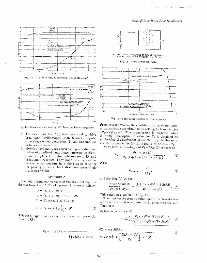
Fig. 13·-·l-!ybrid of Fig. S. Insertion loss vs Ircqucncy.
Fig. 14--l\latchcd rcsisrance hybrid. Insertion loss vs frequency.
4) The cire ui t of Fig. 5 (a) has been used to drivebroadband oscilloscopes, with balanced inputs,Irom single-ended generators. It can aiso find usein balanced detectors.
5) Hybrids have many uses such as in power dividers,balanced ampli tude and phase detectors; as direc-tional couplers for pulse reflectometcrs, IF andbroadband sweepers. They might also be used asnecessary cornponen ts in a short pulse repeaterfor passing pulses in both directions all a singletransmission line.
ApPENDIX A
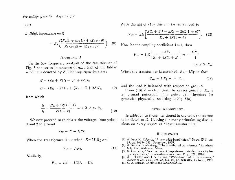
The high frequency response of the circuit of Fig. 3 isderived from Fig. 15. The loop equations are as follows:
(It + Jz)Rg + Vt
(L + Jz)Rg - V2 + J2Ri_
V2 cos {31 + jIzZo sin f31V·,
12 cos {31 + j .-= si n (31..%0
This set of equations is solved for the output power Po.Po== 1121 2RJ,
e=eVt
I, =
[RgRr. +
[+2Rg(l + cos{3l) + RLcos61J2 + Zo Z 2Jo t sin? (3!
From this expression, the conditions for maximum pow-er transmission are obtained by setting 1=0 and settingdPo/dRLI1_O=O. The transformer is matched whenRL = 4Rg. The optimum value ior Z« is obtaincd byminimizing the coefficient of sin? f31 in (3). In this man-ner the proper value for Z« is found to be Zo = 2Rg.
Now, setting RL =4Rg and Zo = 2Rg, (3) reduces to
c2(1 + cos (31)2Po = --- (4)
Rg[(l + 3 cos{3t)2 + 4 ~in2 /3lJ
Also,
e2
Pavnilaule = -r-r--r r
4Rg(5)
(2)
and dividing (4) by (3) :
Power Available (1 + 3 cos (31)2 + 4 sin" (31= . (6)
Power Output 4(1 -I- cos (31)2
This function is plotted in Fig. 16.The impedances seen at either end of the transformer
with the other end terminated in ZL have been derived.They are:
Z;,,(low impedance end)
(Z L cos {3t +tz, sin (3l )
= z, 2Zo(1 + cos{3l) +'jZr. sin fJI (7)
(3)
163
Proceedingsof the Ire August 1959
and
Zin(high impedance end)
_ r (2Z L(l + cos (jl) + tz, sin f3l)- Zo .
Z« cos (3l + JZL sin {31
ArPENDIX BIn the low frequency analysis of the transformer of
Fig. 5 the series impedance of each half of the bifilarwinding is denoted by Z. The loop equations are:
E = (Rg + Z)ft - (2 + kZ)1z
E = (Rg - kZ)II + (RD + Z + kZ)Iz,
from which
11 RL + 2Z(1 + k)- = ------ = 2 if 2» RI,.
12 Z(1 + k)
We now proceed to calculate the voltages from points1 and 2 to ground
When the transformer is matched, E=2hRg and
Si milady,
Vw = hZ -- kZ(l1 - 12).
-VVith the aid of (10) th is can be rearranged to
_ r [Z(1 + sv - kRr, - 2kZ(1 + k)]Vw - Z11 . •
Rr, + 2Z(1 + k)(12)
(8) Now let the coupling coeJlicient k = 1, then
[-kRI" ] t.u:
Vir. = IIZ RL + 2Z(1 + k) ~ - 4
for Z» RL.
When the tr ansf or mer is matched, R/"=4Rg so that
(13)
(9) and the load is balanced with respect to ground.From (13) it is clear that the center point of RJ- IS
at ground potential. This point can therefore begrounded physically, resulting in Fig. 5(a).
(10) ACKNOWLEDGMENT.
I n addition to those mentioned in the text, the authoris indebted to D. II. Ring for many stimulating discus-sions on every aspect of these transformers.
REFERENCES
III Willmor K. Roberts, "A new wide-band balun," PROC. I RE, vol.45, pp. 1628-1631; December, 1957.
[2] H. Gunther Rudenberg, "The distributed transformer," RaytheonMfg. Co., Waltham, Mass.
l3] G. Guane!la, "New method of impedance matching in radio Ire-queucy circuits," Brown-Boveri Reo., voL 31, p, 327; 1944.
f4] A. I. Talkin and J. V. Cuneo, "Wide-band balun transformer,"Reuieui of Sci. Inst., vol. 28, No. 10, pp. 808-815; October, 1957.