58
FILTEK FILTEK RF & Microwave Fil t ers Catalog #128

FILTEKFILTEKRF & Microwave Filters
Catalog #128

FILTEKFILTEK
RF & Microwave Filters
2 RF & Microwave Filters
Terms and Conditions of Sale:General Ordering Information Page 3
Model Numbering System Page 4
Glossary Page 5
General Performance Specifications Page 8
Connector Types Page 12
BANDPASS:
Tubular Page 13
Lumped Element Page 19
Miniature Helical Page 23
Cavity Page 26
Combline and Interdigital Page 34
Tunable Page 38
LOWPASS:
Tubular Page 39
Lumped Element Page 42
HIGHPASS:
Lumped Element Page 46
Suspended Substrate Page 49
BANDREJECT:
Lumped Element Page 51
Cavity Page 52
Tunable Page 55
Contents

3RF & Microwave Filters
Terms and Conditions of SaleGeneral Ordering
InformationHow to order:
If ordering a standard filter, a Model number is all that is necessary. Contact application engineering at Filtek or the local Filtek representative for any special requirements. For more information on Model numbers see page 4.
Ordering Address:
Orders should be made out to:
Filtek4410-A Hawkins St. NEAlbuquerque NM 87109
Phone (505) 345-1486
Facsimile (928) 776-4208
e-mail: [email protected]
Internet: www.filtekfilters.com
Orders by phone or facsimile will be accepted and processed pending receipt of your confirming purchase order.
Prices:Prices will be quoted upon request by the marketing department at Filtek or any authorized Filtek representative. Prices do not include state or local sales, excise or use taxes. These taxes will be added when applicable. Prices are subject to change without prior notice.
Product information:Information relating to Filtek products is current at the time of publication. However, as part of continous improvement programs, Filtek reserves the right to change specifications and designs without prior notice.
Terms and Conditions:Unless customer specifications state otherwise and are quoted as such by Filtek, all sales and quotations are subject to Filtek standard terms and conditions of sale as stated herein. Terms are net 30 days, F.O.B. Factory. Unless credit has already been established, shipments will be made C.O.D. or upon receipt of payment in advance.
Packaging and Delivery:Prices include standard packing, but not shipping. Unless specific instructions are included as part of order, shipment is normally made by FedEx or UPS.
Warranty
Filtek warrants products of its manufacture to be free from defects in material and workmanship under conditions of normal use for a period of one year. If, within one year after delivery to the original owner, and after prepaid return by the original owner any Filtek product is found defective, Filtek shall at its option repair or replace the defective item. This warranty does not apply to products which have been disassembled, modified or subjected to conditions exceeding the applicable specifications or ratings. This warranty is the extent of the obligation or liability assumed by Filtek with respect to its products and no other warranty or guarantee is either expressed or implied. In no event does Filtek assume liability for installation labor or for consequential damages.
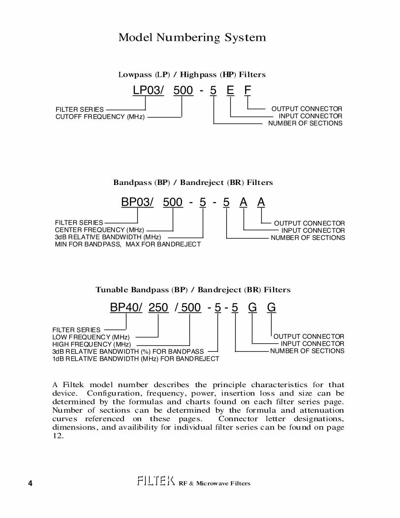
Model Numbering System
Lowpass (LP) / Highpass (HP) Filters
LP03/ 500 - 5 E F
FILTER SERIESCUTOFF FREQUENCY (MHz)
OUTPUT CONNECTORINPUT CONNECTOR
NUMBER OF SECTIONS
Bandpass (BP) / Bandreject (BR) Filters
BP03/ 500 - 5 - 5 A A
FILTER SERIESCENTER FREQUENCY (MHz)3dB RELATIVE BANDWIDTH (MHz)MIN FOR BANDPASS, MAX FOR BANDREJECT
OUTPUT CONNECTORINPUT CONNECTOR
NUMBER OF SECTIONS
Tunable Bandpass (BP) / Bandreject (BR) Filters
BP40/ 250 / 500 - 5 - 5 G G
FILTER SERIESLOW FREQUENCY (MHz)HIGH FREQUENCY (MHz)3dB RELATIVE BANDWIDTH (%) FOR BANDPASS1dB RELATIVE BANDWIDTH (MHz) FOR BANDREJECT
OUTPUT CONNECTORINPUT CONNECTOR
NUMBER OF SECTIONS
A Filtek model number describes the principle characteristics for that device. Configuration, frequency, power, insertion loss and size can be determined by the formulas and charts found on each filter series page. Number of sections can be determined by the formula and attenuation curves referenced on these pages. Connector letter designations, dimensions, and availibility for individual filter series can be found on page 12.
4 RF & Microwave Filters

5
GlossaryAttenuation Loss of signal in transmission through a filter, usually referring to
signal amplitude or signal power. Generally measured in decibels (dB).
Band Reject Filter A filter that rejects one band of frequencies and passes both higher and lower frequencies. Sometimes called a notch filter.
Bandpass Filter A filter that passes one band of frequencies and rejects both higher and lower frequencies.
Bandwidth The width of the passband of a bandpass filter. Usually expressed as the frequency difference between lower and upper 3dB relative points.
Bessel Function A mathematical function used to yield a maximally constant time delay in a filter with no consideration for amplitude response. This function is very close to a Gaussian function.
Butterworth Function A mathematical function used to yield a maximally constant amplitude response in a filter with no consideration for time delay, or phase response.
Center Frequency (Fc) The arithmetic mean frequency normally calculated using the 3dB relative band edges (F1 & F2).
Fc = (F1 + F2)/2
Where F1 and F2 are lower and upper frequencies respectively at which a particular signal attenuation occurs, usually taken as 3dB relative attenuation. An important parameter of bandpass and bandstop filters.
Cut-off Frequency (Fco) The upper passband edge in lowpass filters or the lower passband edge in highpass filters. The passband edge closest to the stop band. Filtek normally uses the point at which the VSWR equals 1.5:1.
Decibel (dB) A unit used to express the ratio between two amounts of power P1 and P2 existing at two points. By definition:
dB = 10 LOG10 (P1/P2)
It can also be used to express voltage and current ratios but only when the voltage or current is measured at places having identical impedance.
Dissipation Energy losses in a filter due to resistive or core losses.
Distortion Generally speaking, the modification of signals which produce an undesirable end effect. These modifications can relate to phase, amplitude, delay, etc. The distortion of a sine wave is usually defined as the percentage of signal power remaining after the fundamental sine wave component has been removed.
Elliptic Function A mathematical function used to yield the squarest possible amplitude filter response with a given number of circuit elements. The elliptic function has a Tchebycheff response in both the passband and the stopband. The elliptic function filter has a poorer phase response and transient response than any of the classical transfer functions.
RF & Microwave Filters

6 RF & Microwave Filters
Envelope Delay The propagation time delay of the envelope of an amplitude modulated signal as it passes through a filter. Sometimes called time delay or group delay. Envelope delay is proportional to the slope of the phase shift response versus frequency curve. Envelope delay distortion occurs when the delay is not constant at all frequencies in the passband area.
Highpass Filter A filter which passes high frequencies and rejects low frequencies.
Input Impedance The impedance measured at the input terminal of a filter when it is properly terminated at its output.
Insertion Loss The loss of signal caused by a filter being inserted in a circuit. It can be expressed in many forms and is usually measured in dB. In general, it is the ratio of voltage delivered to the load (at peak frequency response) with the filter in the circuit, to the voltage in the load if a perfect lossless matching transformer replaced the filter. When a filter is inserted between two circuits whose impedance differs widely, it is sometimes more practical to specify insertion loss by some other method.
Linear Phase Filter A filter that exhibits a constant change in degrees per unit of frequency. The resultant plot of frequency vs. phase is a straight line. This type of filter ideally displays a constant delay in its passband.
Load Impedance The impedance that normally must be connected to the output terminal of the filter in order to meet filter specifications; The filter output will drive this load.
Lowpass Filter A filter which passes low frequencies and rejects high frequencies.
Overshoot The amount in percent by which a signal exceeds its steady-state output on its initial rise.
Passband The frequency range passed by a filter.
Passband Ripple Variations of attenuation with frequency within the passband of a filter.
Phase Shift The changing of phase of a signal as it passes through a filter. A delay in time of the signal is referred to as phase lag and in normal networks , phase lag increases with frequency, producing a positive envelope delay (see envelope delay).
Q The figure of merit of a capacitor or inductor. The ratio of its reactance to its equivalent series resistance. Also in bandpass filters “loaded Q” is a term used to define the percentage of 3 dB bandwidth.
Loaded Q = Center Frequency (Fc) / 3 dB Bandwidth
Relative Attenuation Attenuation measured with the point of minimum attenuation taken as zero dB, or: (Relative Attenuation = Attenuation minus Insertion Loss.)
Return Loss The ratio in dB of maximum power sent down a transmission line to the power returned toward the source. Also equal to 20 times the log of the reciprocal of the reflection coefficient. If return loss is infinite, all power is absorbed in the circuit.

7RF & Microwave Filters
Ringing The tendency of a filter to oscillate for a time when a transient waveform is applied to it.
Ripple Generally referring to the wavelike variations in the amplitude response of a filter. Tchebycheff and elliptic function filters ideally have equi-ripple characteristics, which means that the difference in peaks and valleys of the amplitude response in the passband are always the same. Butterworth, Gaussian, and Bessel functions have no ripple. Ripple is usually measured in dB.
Rise Time The length of time it takes a step-function at the output of a filter to move from 10% to 90% of its steady state value on the initial rise.
Shape Factor An important parameter of all filters:
Bandpass: SF = Attenuation Bandwidth/ 3 dB Bandwidth Bandstop: SF = 3 dB Bandwidth/ Attenuation Bandwidth Lowpass: SF = Attenuation Frequency / Fco Highpass: SF = Fco / Attenuation Frequency
Source Impedance The output impedance of the circuit that drives the filter. The impedance of the circuit the filter must work from or be tested in.
Step Function A signal change in amplitude from one level to another which occurs in zero time. Usually refers to a rectangular front waveform used in testing transient response.
Stopband The area of frequency where it is desirable to reject or attenuate all signals as much as practical.
Tchebycheff Function A mathematical function that produces a curve that defines ripples within certain bounds (see ripple). This function produces a squarer amplitude response than the Butterworth function but with less desirable phase, and time delay characteristics. There is a whole family of Tchebycheff functions (0.1 ripple, 0.5 ripple, etc.).
Time Delay The amount of time it takes for certain signals to pass through a filter.
Transient Response The response of a lowpass filter to a step function, or very low frequency square wave. If a sudden voltage rise is applied to a lowpass filter the output will respond some time later. Transient response can also apply to a bandpass filter responding to a sudden burst of signal within its passband.
Voltage Standing
Wave Ratio (VSWR) The ratio between the peak and valley of standing waves on a transmission time.

8 RF & Microwave Filters
It is often advantageous to know more about the passband of a filter than its center frequency loss and its 3 dB bandwidths. The graphs on this page show the approximate relationships of the 0.5, 1.0 and 2.0 dB relative bandwidths to the 3 dB relative bandwidth. They also serve to illustrate how the number of sections and the insertion loss affect these relationships.
5.0
4.5
4.0
3.5
3.0
2.5
2.0
1.5
1.0
0.5
030 40 50 60 70 80 90 100
Cente
r F
requency
Insert
ion L
oss (
dB
)
% of 3 dB Bandwidth (Typical)
2 S
ectio
n
3 S
ectio
n4 to
6 S
ectio
n
0.5 dB Relative Bandwidth
General Performance Specifications
5.0
4.5
4.0
3.5
3.0
2.5
2.0
1.5
1.0
0.5
030 40 50 60 70 80 90 100
Cente
r F
requency
Insert
ion L
oss (
dB
)
% of 3 dB Bandwidth (Typical)
2 S
ectio
n3 S
ectio
n4 to
6 S
ectio
n1.0 dB Relative Bandwidth
5.0
4.5
4.0
3.5
3.0
2.5
2.0
1.5
1.0
0.5
030 40 50 60 70 80 90 100
Cente
r F
requency
Insert
ion L
oss (
dB
)
% of 3 dB Bandwidth (Typical)
2 S
ectio
n3 S
ectio
n4 to
6 S
ectio
n
2.0 dB Relative Bandwidth

9RF & Microwave Filters
5° phase bandwidth vs. 3 dB bandwidth: This graph should serve as a general guide for filter requirements regarding phase linearity. As an example, a four section filter with an insertion loss of 3.0 dB at center frequency should exhibit ± 5° linearity over 60% of the bandwidth.
General Performance Specifications
5.0
4.5
4.0
3.5
3.0
2.5
2.0
1.5
1.0
0.5
010 20 30 40 50 60 70 80
Cente
r F
requency
Insert
ion L
oss (
dB
)
% of 3 dB Bandwidth (Typical)
2 S
ectio
n
3 S
ectio
n4 to
6 S
ectio
n
5° Relative Phase Bandwidth
0
10
20
30
40
50
60
70
80
90
1001.05 1.06 1.07 1.08 1.09 1.10 1.11 1.12
3 d
B%
Bandw
idth
Factor
Since the 3 dB bandwidth is a minimum bandwidth, the typical maximum bandwidth may be of some concern. This graph defines the typical variation incurred in the manufacturing process.
For example, in a bandpass filter: Center Frequency = 100 MHz3 dB Bandwidth = 30 MHz3 dB % Bandwidth = 30%
From the chart at 30%, the factor = 1.10, therefore the 3 dB relative bandwidth could vary from 30 MHz to 33 MHz.

10 RF & Microwave Filters
General Performance Specifications
This graph shows the approximate relationship of the 1.5:1 VSWR bandwidth to the 3 dB relative bandwidth. It also serves to illustrate how the number of sections and the insertion loss affect these relationships.
Diplexers and Multiplexers
Filters within any of the bandpass series or combinations of different series may be used to form the basic networks of diplexers or multiplexers.
One terminal of each filter network is common to the assembly, the other terminals remain separate and are isolated from each other. Thus signals applied to the common terminal are separated in accordance with the passband frequencies of the filter networks; Signals applied to the isolated terminals are combined at the common terminal.
The passband of the individual network may be contiguous or separated by overlapping stopbands. For information regarding your specific applications contact Filtek.
Frequency
Insert
ion L
oss
5.0
4.5
4.0
3.5
3.0
2.5
2.0
1.5
1.0
0.5
050 60 70 80 90 100110 120
Cente
r F
requency
Insert
ion L
oss (
dB
)
% of 3 dB Bandwidth
2 S
ection
3 S
ection 4
Section 5
Sect
ion
6 o
r m
ore
Sect
ions

11RF & Microwave Filters
General Performance Specifications
2000
4000
6000
8000
10000
12000
14000
16000
2000
4000
6000
8000
10000
12000
14000
16000
-1.0 -.8 -.6 -.4 -.2 Fc +.2 +.4 +.6 +.8 +1.0
TIM
E F
AC
TO
R
TIM
E F
AC
TO
R
2 Section
3 Section
4 Section
5 Section
6 Section
7 Section
LOWER
3dB POINT
UPPER
3dB POINT
Group Delay
The approximate Group Delay of a FILTEK bandpass filter can be calculated as follows:
Time Factor
3dB BW (MHz) x π= Delay in nSec
Example:
The approximate Group Delay at Fc for a four section filter with 3dB BW equal to 200 MHz would be:
3000 3000
200 x 3.14 628= 4.8 nSec=
This same filter would have an approximate Group Delay of 9.4 nSec at +/- 90 MHz (+/- 90% of the 3dB bandwidth)
5800 5800
200 x 3.14 628= 9.3 nSec=

Connectors General
12 RF & Microwave Filters
0.375 0.510 0.750 0.845 0.750 0.875 0.750 0.825
0.375 0.510
0.375 0.510 0.750 0.845 0.750 0.875 0.750 0.825
0.375 0.510 0.750 0.845 0.750 0.875 0.750 0.825
0.375 0.510 0.750 0.845 0.750 0.875 0.750 0.825 0.125 0.125
0.125 0.1250.310 0.465
0.375 0.510 0.750 0.845 0.750 0.875 0.750 0.819 0.1250.750 0.875
0.125 0.1250.310 0.465
0.125
TNC Jac
k
Configuration !BandpassBP02BP03BP04BP11BP12BP13BP15BP21BP22BP23BP24BP25BP26BP30BP31BP32BP40LowpassLP02LP03LP04LP11LP12LP13HighpassHP11HP12HP13HP35BandrejectBR11BR21BR22BR30BR40Configuration !
SMA J
ack
SMA P
lug
TNC P
lug
BNC Jac
k
BNC P
lug
N Jac
k
N P
lug
C Jac
k
C P
lug
Cab
le R
G 1
88
Solde
r Pin A
xial
Solde
r Pin R
adial
Special
A B C D E F G H J K L M N S
0.800 0.965 0.300
0.800 0.965 1.000 0.935 1.000 0.935 1.275 1.235 0.3001.125 1.218
0.800 0.965 1.350 1.280 1.350 1.280 1.650 1.625 0.3001.125 1.218
0.375 0.510 0.750 0.845 0.750 0.875 0.750 0.825 0.1250.750 0.875
0.125 0.1250.310 0.465
0.125
0.375 0.465
0.375 0.510 0.750 0.845 0.750 0.875 0.750 0.825
0.375 0.510 0.750 0.845 0.750 0.875 0.750 0.825
0.375 0.510 0.750 0.845 0.750 0.825
0.375 0.510 0.750 0.845 0.750 0.825
0.375 0.510 0.750 0.845 0.750 0.825
0.375 0.510 0.750 0.845 0.750 0.825
0.375 0.510
0.375 0.510
0.310 0.465
0.375 0.510 0.750 0.845 0.750 0.875 0.750 0.825
0.125
0.800 0.965 1.000 0.935 1.000 0.935 1.275 1.235 0.300
0.800 0.965 1.000 0.935 1.000 0.935 1.275 1.235 0.300 0.3001.125 1.218
0.800 0.965 1.350 1.280 1.350 1.280 1.650 1.625 0.300 0.3001.125 1.218
0.375 0.510 0.750 0.845 0.750 0.875 0.750 0.825 0.1250.750 0.875 0.125
0.125
0.125 0.1250.375 0.510
0.125 0.125 "
"
"
"
"
"
"
""
""
""
""
""
""
""
""
""
""
""
""
""
""
""
""
""
""
""
""
""
""
""
""
""
""
""
""
""
""
""
A B C D E F G H J K L M N S
""
0.125
""
" Per Customer Requirements"" Per Customer Requirements; Contact Filtek for Feasibility
This chart shows the availability and and sizes of various connectors for Filtek filters. The configuration letter associated with each connector type (A thru S) should be used as a part of the part number when ordering. See page 4 for part number detail. Contact Filtek for your special requirements which are not shown here.
0.750
0.750
0.845
0.845
0.750
0.750
0.825
0.825

The Maximum Insertion Loss at Center Fre-quency is equal to:
The approximate length of a FILTEK BP02 series filter can be determined by adding the 'C' dimensions found on page 12 to the 'L' dimension found in the table at the right. Please contact the factory if exact dimensions are required.
The approximate weight is .50 ounce per inch.
Specifications
Electrical
Environmental
Center Frequency (Fc)3 dB Relative Bandwidth (% of Fc)Number of Sections AvailableNominal ImpedanceMaximum VSWRMaximum Fc Insertion LossStopband AttenuationAverage Power (Watts Max to 10K Feet)Peak Power (Watts Max to 10K Feet)
250 to 4000 MHz2 to 403 to 850 Ohms1.5:1See Chart BelowSee Curve Page 16(2 x % BW) / Loss Factor1.5 x % BW
Insertion Loss
100 to 5000 MHz1 to 1002 to 1275 or 100 Ohms1.25:1See Chart BelowSee Curve Page 16
7500
STANDARD SPECIAL
STANDARD SPECIAL
13
(2.9 x 5.5) / 20 + 0.2 = 0.99 dB
RF & Microwave Filters
Numberof
Sections
3
4
5
6
7
8
Center Frequency (MHz)
250to
300
301to
350
351to
750
751to
1250
1251to
4000
3.00
3.75
4.50
5.25
6.00
6.75
2.75
3.50
4.25
5.00
5.75
6.50
2.37
3.00
3.62
4.25
4.87
5.50
2.00
2.50
3.00
3.50
4.00
4.50
1.75
2.12
2.50
2.87
3.25
3.62
Tubular Bandpass BP02 Series 100 to 5000 MHz
Example:The maximum loss for a 5 Section BP02 Series filter with Fc at 750 MHz and 3 dB Bandwidth of 150 MHz is
Center Frequency (MHz)
Loss Factor 3.4 3.1 2.9 2.6 2.4
Loss Factor (Number of Sections + 0.5)+ 0.2
% 3 dB Bandwidth
C L C
3/8" Dia.
250to
300
301to
350
351to
750
751to
1250
1251to
4000
10 G30 G90 % Relative 0° to +50° C.-25° to +75° C.
50 G100 G100 % Relative-25° to +100° C.-54° to +125° C.
Vibration (10 to 2000 Hz)Shock (11 mSec)HumidityOperating TemperatureNon-Operating Temperature

The approximate length of a FILTEK BP03 series filter can be determined by adding the 'C' dimensions found on page 12 to the 'L' dimension found in the table at the right. Please contact the factory if exact dimensions are required.
The approximate weight is .75 ounce per inch.
Specifications
Electrical
Environmental
Vibration (10 to 2000 Hz)Shock (11 mSec)HumidityOperating TemperatureNon-Operating Temperature
10 G30 G90 % Relative 0° to +50° C.-25° to +75° C.
Center Frequency (Fc)3dB Relative Bandwidth (% of Fc)Number of Sections AvailableNominal ImpedanceMaximum VSWRMaximum Fc Insertion LossStopband AttenuationAverage Power (Watts Max to 10K Feet)Peak Power (Watts Max to 10K Feet)
100 to 2500 MHz2 to 403 to 850 Ohms1.5:1See Chart BelowSee Curve Page 16(3 x % BW) / Loss Factor3 x % BW
Insertion Loss
50 to 4000 MHz1 to 1002 to 1275 or 100 Ohms1.25:1See Chart BelowSee Curve Page 16
10,000
STANDARD SPECIAL
50 G100 G100 % Relative-25° to +100° C.-54° to +125° C.
STANDARD SPECIAL
14
(2.2 x 4.5) / 5 + .2 = 2.18 dB
RF & Microwave Filters
Numberof
Sections
3
4
5
6
7
8
Center Frequency (MHz)100to
200
201to
400
401to
1000
1001to
1500
1501to
2500
3.75
4.75
5.75
6.75
7.75
8.75
2.75
3.50
4.00
4.75
5.50
6.00
2.37
3.00
3.50
4.25
4.87
5.50
2.00
2.50
3.00
3.50
4.00
4.50
1.75
2.00
2.50
3.00
3.50
4.00
Center Frequency
(MHz)
201to
400
401to
1000
1001to
1500
1501to
2500
100to
200
Loss Factor 3.0 2.5 2.2 2.0 1.9
The Maximum Insertion Loss at Center Fre-quency is equal to:
Example:The maximum loss for a 4 Section BP03 Series filter with a center frequency of 500 MHz and a 3 dB Bandwidth of 25 MHz is:
Loss Factor (Number of Sections + 0.5)+ 0.2
% 3 dB Bandwidth
Tubular Bandpass BP03 Series 50 to 4000 MHz
1/2" Dia.
C L C

Specifications
Electrical
Environmental
Insertion Loss
STANDARD SPECIAL
STANDARD SPECIAL
15
(2.1 x 4.5) / 5 + .2 = 2.09 dB
RF & Microwave Filters
Center Frequency
(MHz)
Loss Factor 2.6 2.4 2.1 1.7 1.4
Numberof
Sections
3
4
5
6
7
8
Center Frequency (MHz)50to65
66to80
81to
150
151to
1000
1001to
1500
6.50
8.00
9.50
12.00
13.50
15.00
5.25
6.50
8.00
9.25
10.75
12.00
4.00
5.00
6.00
7.00
8.00
9.00
2.50
3.25
4.00
4.75
5.25
6.00
2.00
2.50
3.00
3.50
4.00
4.50
Tubular Bandpass BP04 Series 30 to 2000 MHz
3/4" Dia.
C L C
The approximate length of a FILTEK BP04 series filter can be determined by adding the 'C' dimensions found on page 12 to the 'L' dimension found in the table at the right. Please contact the factory if exact dimensions are required.
The approximate weight is 1.0 ounce per inch.
Center Frequency (Fc)3 dB Relative Bandwidth (% of Fc)Number of Sections AvailableNominal ImpedanceMaximum VSWRMaximum Fc Insertion LossStopband AttenuationAverage Power (Watts Max to 10K Feet)Peak Power (Watts Max to 10K Feet)
50 to 1500 MHz2 to 403 to 850 Ohms1.5:1See Chart BelowSee Curve Page 16(5 x % BW) / Loss Factor4 x % BW
30 to 2000 MHz1 to 1002 to 1275 or 100 Ohms1.25:1See Chart BelowSee Curve Page 16
10,000
The Maximum Insertion Loss at Center Fre-quency is equal to:
Example:The maximum loss for a 4 Section BP04 Series filter with a center frequency of 100 MHz and a 3 dB Bandwidth of 5 MHz is:
Loss Factor (Number of Sections + 0.5)+ 0.2
% 3 dB Bandwidth
Vibration (10 to 2000 Hz)Shock (11 mSec)HumidityOperating TemperatureNon-Operating Temperature
5 G15 G90 % Relative 0° to +50° C.-25° to +75° C.
30 G75 G100 % Relative-25° to +100° C.-54° to +125° C.
50to65
66to80
81to
150
151to
1000
1001to
1500

16 RF & Microwave Filters
Stopband Attenuation Tubular Bandpass
The graphs on the following pages define the normal specification limits of attenuation for FILTEK Tubular bandpass filters. The minimum level of attenuation in dB is shown as a "Number of 3dB Bandwidths from Center Frequency." Since the filter characteristics vary for differing bandwidths, it is necessary to establish specifications for each bandwidth of filter. The different graphs represent the various 3dB percentage bandwidths. The 3dB percentage bandwidth is defined as follows:
Rejection Frequency (MHz) - Center Frequency (MHz)3dB Bandwidth (MHz)
3dB Bandwidth (MHz) x 100Center Frequency (MHz)
= % Bandwidth
The exact relationship is as follows:
1. 3dB bandwidth from center frequency=
2. Center Frequency = 500 MHz Minimum 3dB Bandwidth= 50 MHz Number of section = 5
Find: Minimum attenuation levels at 425 MHz and 580 MHz.
3dB bandwidths from Fc; (425-500)/50=-1.5 and (580-500)/50=+1.6
As the 3dB Bandwidth is exactly 10% of the center frequency, the answer can be read directly from the 6-15% graph. Using the 5 section curve at the point -1.5 (425 MHz), the minimum level of attenuation is 40dB. At +1.6 (580 MHz), the minimum level of attenuation is 51dB.
Example:

20
30
40
50
60
70
10
- 5 - 4 - 3 - 2 - 1 0 + 1 + 2 + 3 + 4 + 5
Att
enu
atio
n (
dB
)
20
30
40
50
60
70
10
2 Section
3 Sectio
n
4 Sec
tion
5 S
ectio
n
6 S
ectio
n8 S
ectio
n
2 Section
3 Section4 S
ection
5 S
ectio
n
6 S
ectio
n
8 S
ectio
n
Number of 3dB Bandwidths from Fc
Stopband Attenuation
2-5% Bandwidths
Tubular Bandpass
20
30
40
50
60
70
10
- 5 - 4 - 3 - 2 - 1 0 + 1 + 2 + 3 + 4 + 5
Att
en
uati
on
(d
B)
20
30
40
50
60
70
10
Number of 3dB Bandwidths from Fc
6-15% Bandwidths
2 Section
3 Sectio
n
4 Sec
tion
5 S
ecti
on
6 S
ectio
n8 S
ecti
on
2 Section
3 Sectio
n
4 S
ectio
n
5 S
ectio
n
6 S
ectio
n
8 S
ectio
n
Atte
nu
atio
n (d
B)
Atte
nu
atio
n (d
B)
17RF & Microwave Filters

20
30
40
50
60
70
10
- 5 - 4 - 3 - 2 - 1 0 + 1 + 2 + 3 + 4 + 5
Number of 3dB Bandwidths from Fc
Att
enu
atio
n (
dB
)
20
30
40
50
60
70
10
Atte
nu
atio
n (d
B)
16 - 30% Bandwidths
31 - 70% Bandwidths
20
30
40
50
60
70
10
- 5 - 4 - 3 - 2 - 1 0 + 1 + 2 + 3 + 4 + 5
Number of 3dB Bandwidths from Fc
Att
enu
atio
n (
dB
)
20
30
40
50
60
70
10
Atte
nu
atio
n (d
B)
Stopband Attenuation Tubular Bandpass
2 Sectio
n
3 Sec
tion
4 Sec
tion
5 S
ecti
on6 S
ecti
on
8 S
ecti
on
3 S
ectio
n
4 S
ectio
n
5 S
ectio
n
6 S
ectio
n
8 S
ectio
n
2 S
ectio
n
3 S
ectio
n
4 S
ecti
on
5 S
ectio
n6 S
ecti
on
8 S
ectio
n
2 Sectio
n
3 S
ectio
n
4 S
ectio
n
5 S
ectio
n6 s
ectio
n
8 S
ectio
n
2 Sectio
n
18 RF & Microwave Filters

Specifications
Electrical
Environmental
Insertion Loss
STANDARD SPECIAL
STANDARD SPECIAL
19
(4.9 x 3.5) / 10 + 0.2 = 1.91dB
RF & Microwave Filters
2.38 1.06.06 TYP
.06 TYP
1.00
2-56 NC2Bx 3/16" Deep CC
Center Frequency
(MHz)
Loss Factor 6.0 5.5 5.2 5.0 4.9
10to15
16to20
21to30
31to 50
51to
150
Lumped Element Bandpass BP11 Series 10 to 250 MHz
Center Frequency (Fc)3dB Relative Bandwidth (% of Fc)Number of Sections AvailableNominal ImpedanceMaximum VSWRMaximum Fc Insertion LossStopband AttenuationAverage Power (Watts Max to 10K Feet)Peak Power (Watts Max to 10K Feet)
10 to 150 MHz2 to 603 to 650 Ohms1.5:1See Chart BelowSee Curve Page 2215
10 to 250 MHz1 to 1002 to 1075 or 100 Ohms1.25:1See Chart BelowSee Curve Page 22515
The Maximum Insertion Loss at Center Fre-quency is equal to:
Example:The maximum loss for a 3 Section BP11 Series filter with a center frequency of 90 MHz and a 3 dB Bandwidth of 9 MHz is:
Loss Factor (Number of Sections + 0.5)+ 0.2
% 3 dB Bandwidth
5 G15 G90 % Relative 0° to +50° C.-25° to +75° C.
10 G30 G100 % Relative-25° to +125° C.-62° to +150° C.
Vibration (10 to 2000 Hz)Shock (11 mSec)HumidityOperating TemperatureNon-Operating Temperature
See Page 12 for 'C' dimensions and other connector configurations. The size shown is a standard used by FILTEK to facilitate a low cost, easily reproducible unit. Should you require another size, please submit all of your requirements - both electrical and mechanical. This will enable FILTEK to quote the optimum design for your application.

Specifications
Electrical
Environmental
Insertion Loss
STANDARD SPECIAL
STANDARD SPECIAL
20
(4.0 x 3.5) / 20 + .2 = 0.9 dB
RF & Microwave Filters
0
.75
0
0
.218
.436
.062
.375
0
.312
.06
2
.68
8
.017 DIAX .125 LONG6 PLACES
.375
0
.436
.062
.312
0
.156
1.0
00
IN OUT
0
Center Frequency
(MHz)
Loss Factor 6.0 5.5 4.7 4.0 3.3
250to
300
301to
400
401to
500
501to
1000
1001to
2500
Lumped Element Bandpass BP12 Series 100 to 5000 MHz
Center Frequency (Fc)3 dB Relative Bandwidth (% of Fc)Number of Sections AvailableNominal ImpedanceMaximum VSWRMaximum Fc Insertion LossStopband AttenuationAverage Power (Watts Max to 10K Feet)Peak Power (Watts Max to 10K Feet)
250 to 2500 MHz5 to 203 to 650 Ohms1.5:1See Chart BelowSee Curve Page 22210
100 to 5000 MHz3 to 1002 to 1075 or 100 Ohms1.25:1See Chart BelowSee Curve Page 22420
+ 0.2
The Maximum Insertion Loss at Center Fre-quency is equal to:
Example:The maximum loss for a 3 Section BP12 Series filter with a center frequency of 1000 MHz and a 3 dB Bandwidth of 200 MHz is:
Loss Factor (Number of Sections + 0.5)
% 3 dB Bandwidth
10 G30 G90 % Relative 0° to +50° C.-25° to + 75° C.
50 G100 G100 % Relative-54° to +125° C.-62° to +150° C.
Vibration (10 to 2000 Hz)Shock (11 mSec)HumidityOperating TemperatureNon-Operating Temperature
.218
C
.93
8
0-80 NFx 3/16" DEEP
.06
2MM Configuration
See Page 12 for 'C' dimensions and other connector configurations. The size shown is a standard used by FILTEK to facilitate a low cost, easily reproducible unit. Should you require another size, please submit all of your requirements - both electrical and mechanical. This will enable FILTEK to quote the optimum design for your application.

Specifications
Electrical
Environmental
Insertion Loss
STANDARD SPECIAL
STANDARD SPECIAL
21
(4.0 x 3.5) / 10 + .2 = 1.6 dB
RF & Microwave Filters
.316
.316
.60 DIA
.350
.017/.020 DIA.
.125 TYP
IN/OUT
IN/OUT
Center Frequency
(MHz)
Loss Factor 6.0 5.5 4.7 4.0 3.3
250to
301
301to
400
401to
500
501to
1000
1001to
2500
Lumped Element Bandpass BP13 Series 100 to 5000 MHz
Center Frequency (Fc)3 dB Relative Bandwidth (% of Fc)Number of Sections AvailableNominal ImpedanceMaximum VSWRMaximum Fc Insertion LossStopband AttenuationAverage Power (Watts Max to 10K Feet)Peak Power (Watts Max to 10K Feet)
250 to 2500 MHz5 to 203 to 550 Ohms1.5:1See Chart BelowSee Curve Page 22210
100 to 5000 MHz3 to 1002 to 675 or 100 Ohms1.25:1See Chart BelowSee Curve Page 22420
+ 0.2
The Maximum Insertion Loss at Center Fre-quency is equal to:
Example:The maximum loss for a 3 Section BP13 Series filter with a center frequency of 1000 MHz and a 3 dB Bandwidth of 100 MHz is:
Loss Factor (Number of Sections + 0.5)
% 3 dB Bandwidth
10 G30 G90% Relative 0° to +50° C.-25° to + 75° C.
50 G100 G100 % Relative-54° to +125° C.-62° to +150° C.
Vibration (10 to 2000 Hz)Shock (11 mSec)HumidityOperating TemperatureNon-Operating Temperature
The size shown is a standard used by FILTEK to facilitate a low cost, easily reproducible unit. Should you require another size, please submit all of your requirements - both electrical and mechanical. This will enable FILTEK to quote the optimum design for your application.
22 RF & Microwave Filters
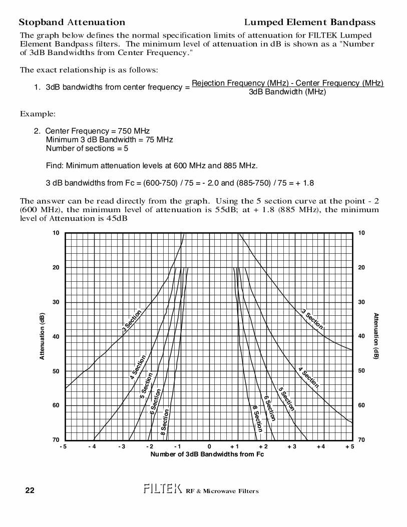
Stopband Attenuation Lumped Element Bandpass
The graph below defines the normal specification limits of attenuation for FILTEK Lumped Element Bandpass filters. The minimum level of attenuation in dB is shown as a "Number of 3dB Bandwidths from Center Frequency."
The exact relationship is as follows:
1. 3dB bandwidths from center frequency =
Example:
2. Center Frequency = 750 MHz Minimum 3 dB Bandwidth = 75 MHz Number of sections = 5
Find: Minimum attenuation levels at 600 MHz and 885 MHz.
3 dB bandwidths from Fc = (600-750) / 75 = - 2.0 and (885-750) / 75 = + 1.8
The answer can be read directly from the graph. Using the 5 section curve at the point - 2 (600 MHz), the minimum level of attenuation is 55dB; at + 1.8 (885 MHz), the minimum level of Attenuation is 45dB
Rejection Frequency (MHz) - Center Frequency (MHz)3dB Bandwidth (MHz)
20
30
40
50
60
70
10
- 5 - 4 - 3 - 2 - 1 0 + 1 + 2 + 3 + 4 + 5
8 S
ecti
on
Att
enu
atio
n (
dB
)
20
30
40
50
60
70
10
3 Sec
tion
4 S
ectio
n5 S
ectio
n6 S
ecti
on
3 Section
4 Section
5 S
ectio
n
6 S
ectio
n
8 S
ectio
n
Number of 3dB Bandwidths from Fc
Atte
nuatio
n (d
B)

Specifications
Electrical
Environmental
Vibration (10 to 2000 Hz)Shock (11 mSec)HumidityOperating TemperatureNon-Operating Temperature
Center Frequency (Fc)3 dB Relative Bandwidth (% of Fc)Number of Sections AvailableNominal ImpedanceMaximum VSWRMaximum Fc Insertion LossStopband AttenuationAverage Power (Watts Max to 10 K Feet) Peak Power (Watts Max to 10 K Feet)
Insertion Loss
The Maximum Insertion Loss at Center Frequency is equal to:
STANDARD SPECIAL
STANDARD SPECIAL
23RF & Microwave Filters
Example :
The maximum loss for a 3 Section BP15 Series filter with a center frequency of 350 MHz and a 3 dB Bandwidth of 35 MHz is:
Center Frequency (MHz)
Loss Factor
250to
300
Miniature Helical Bandpass BP15 Series 100 to 1000 MHz
Loss Factor (Number of Sections +.5)+ 0.1
% 3 dB Bandwidth
(3.6 x 3.5) / 10 + 0.1 = 1.36 dB
4.2 3.6 3.4 3.1
200 to 750 MHz3 to 153 to 650 Ohms1.5:1See Chart BelowSee curve Page 24% BW/Loss Factor% BW
100 to 1000 MHz1 to 202 to 1050 Ohms1.25:1See Chart BelowSee curve Page 24515
10 G15 G90 % Relative0° to + 50° C.-25° to + 75° C.
15 G30 G100 % Relative-54° to + 125° C.-62° to + 150° C.
301to
400
401to
600
601to
750
L
.13
0.036 TYPICALC
0.100"
.69
.34
0.125"
L
0.100"
2-56 NC2Bx 3/16 DEEP4 PLACES
No. of Sections / 2 (Approx)
.38
See Page 12 for 'C' dimensions and other connector configurations. The size shown is a standard used by FILTEK to facilitate a low cost, easily reproducible unit. Should you require another size, please submit all of your requirements - both electrical and mechanical. This will enable FILTEK to quote the optimum design for your application.

24 RF & Microwave Filters
Stopband Attenuation Miniature Helical Bandpass
The graphs on the following pages define the normal specification limits of attenuation for FILTEK Miniature Helical Bandpass filters. The minimum level of attenuation in dB is shown as a "Number of 3dB Bandwidths from Center Frequency." Since the filter characteristics vary for differing bandwidths, it is necessary to establish specifications for each bandwidth of filter. The different graphs represent the various 3dB percentage bandwidths. The 3dB percentage bandwidth is defined as follows: 3 dB Bandwidth (MHz) x 100 Center Frequency (MHz)
The exact relationship is as follows:
1. 3 dB bandwidths from center frequency =
Example:
2. Center Frequency = 500 MHz Minimum 3 dB Bandwidth = 50 MHz Number of sections = 5
Find: Minimum attenuation levels at 400 MHz and 600 MHz.
3 dB bandwidths from Fc = (400-500) / 50 = - 2.0 and (600-500) / 50 = + 2.0
As the 3dB Bandwidth is exactly 10% of the center frequency, the answer can be read directly from the 6-10% graph. Using the 5 section curve at the point -2.0 (400 MHz), the minimum level of attenuation is 63dB; at + 2.0 (600 MHz), the minimum level of attenuation is 54dB.
Rejection Frequency (MHz) - Center Frequency (MHz)3 dB Bandwidth (MHz)
20
30
40
50
60
70- 5 - 4 - 3 - 2 - 1 0 + 1 + 2 + 3 + 4 + 5
8 S
ectio
n
Att
en
uati
on
(dB
)
20
30
40
50
60
70
3 Sec
tion
4 S
ectio
n5 S
ectio
n6 S
ecti
on
3 Section
4 Section
5 S
ectio
n
6 S
ectio
n
8 S
ectio
n
Number of 3dB Bandwidths from Fc
7 S
ecti
on
7 S
ectio
n
Atte
nuatio
n (d
B)
=% Bandwidth
3 -5 % Bandwid ths

25RF & Microwave Filters
Stopband Attenuation Miniature Helical Bandpass
20
30
40
50
60
70- 5 - 4 - 3 - 2 - 1 0 + 1 + 2 + 3 + 4 + 5
8 S
ecti
on
Att
en
ua
tio
n (
dB
)
20
30
40
50
60
70
3 S
ection
4 S
ecti
on
5 S
ection
6 S
ecti
on
3 Sectio
n
4 Sectio
n
5 S
ectio
n
6 S
ectio
n
8 S
ectio
n
Number of 3dB Bandwidths from Fc
7 S
ecti
on
7 S
ectio
n
Atte
nu
atio
n (d
B)
20
30
40
50
60
70- 5 - 4 - 3 - 2 - 1 0 + 1 + 2 + 3 + 4 + 5
8 S
ecti
on
Att
en
uati
on
(d
B)
20
30
40
50
60
70
3 Sec
tion
4 S
ecti
on
5 S
ecti
on
6 S
ecti
on
3 Sectio
n
4 Sectio
n
5 S
ectio
n
6 S
ectio
n
8 S
ectio
n
Number of 3dB Bandwidths from Fc
7 S
ecti
on
7 S
ectio
n
Atte
nu
atio
n (d
B)
6-10% Bandwidths
11-15% Bandwidths

Specifications
Electrical
Environmental
Insertion Loss
STANDARD SPECIAL
STANDARD SPECIAL
26 RF & Microwave Filters
Center Frequency
(MHz)
Loss Factor
30
to
50
51
to
70
71
to
100
101
to
300
301
to
450
Cavity Bandpass BP21 Series 20 to 600 MHz
.19 TYPICAL
.50TYPICAL
L
L + .75
C
.13
1.25
W
Sections L Dimension
2
3
4
5
6
2.50
3.62
4.75
5.87
7.00
Frequency W Dimension
30-50 MHz
50-65 MHz
65-100 MHz
100-450 MHz
3.87
2.87
2.37
1.87
Vibration (10 to 2000 Hz)Shock (11 mSec)HumidityOperating TemperatureNon-Operating Temperature
Center Frequency (Fc)3 dB Relative Bandwidth (% of Fc)Number of Sections AvailableNominal ImpedanceMaximum VSWRMaximum Fc Insertion LossStopband AttenuationAverage Power (Watts Max to 10 K Feet) Peak Power (Watts Max to 10 K Feet)
The Maximum Insertion Loss at Center Frequency is equal to:
Example
The maximum loss for a 3 Section BP21 Series filter with a center frequency of 200 MHz and a 3 dB Bandwidth of 4 MHz is:
Loss Factor (Number of Sections +.5)+ 0.1
% 3 dB Bandwidth
(1.4 x 3.5) / 2 + 0.1 = 2.55 dB
1.8 1.6 1.5 1.4 1.0
30 to 450 MHz1 to 33 to 650 Ohms1.5:1See Chart BelowSee curve Page 32(3 x % BW)/Loss Factor15 x % BW
20 to 600 MHz0.2 to 42 to 750 Ohms1.25:1See Chart BelowSee curve Page 3220100
5 G5 G90 % Relative0° to + 50° C.-25° to + 70° C.
15 G15 G100 % Relative-54° to + 100° C.-54° to + 125° C.
Accepts#8 Screw
See Page 12 for 'C' dimensions and other connector configurations. The size shown is a standard used by FILTEK to facilitate a low cost, easily reproducible unit. Should you require another size, please submit all of your requirements - both electrical and mechanical. This will enable FILTEK to quote the optimum design for your application.

Specifications
Electrical
Environmental
Insertion Loss
STANDARD SPECIAL
STANDARD SPECIAL
27RF & Microwave Filters
Center Frequency
(MHz)
Loss Factor
400
to
500
501
to
800
801
to
900
901
to
1300
1301
to
3050
Cavity Bandpass BP22 Series 250 to 4000 MHz
.19 TYPICAL
.50 TYPICAL
L
L + .75
C
.13
1.25
W
Sections L Dimension
2
3
4
5
6
2.50
3.62
4.75
5.87
7.00
Frequency W Dimension
400-600 MHz
600-900 MHz
900-1300 MHz
1300-1800 MHz
4.87
3.87
2.87
2.37
Vibration (10 to 2000 Hz)Shock (11 mSec)HumidityOperating TemperatureNon-Operating Temperature
Center Frequency (Fc)3 dB Relative Bandwidth (% of Fc)Number of Sections AvailableNominal ImpedanceMaximum VSWRMaximum Fc Insertion LossStopband AttenuationAverage Power (Watts Max to 10K Feet) Peak Power (Watts Max to 10K Feet)
The Maximum Insertion Loss at Center Frequency is equal to:
Example:
The maximum loss for a 3 Section BP22 Series filter with a center frequency of 750 MHz and a 3 dB Bandwidth of 15 MHz is:
Loss Factor (Number of Sections +.5)+ 0.1
% 3 dB Bandwidth
(0.5 x 3.5) / 2 + 0.1 = 0.98 dB
0.6 0.5 0.4 0.35 0.3
400 to 3000 MHz0.3 to 33 to 650 Ohms1.5:1See Chart BelowSee curve Page 32See Peak15 x % BW
250 to 4000 MHz0.2 to 52 to 750 Ohms1.25:1See Chart BelowSee Curve Page 32See Peak200
5 G5 G90 % Relative0° to + 50° C.-25° to + 70° C.
15 G15 G100 % Relative-54° to + 100° C.-54° to + 125° C.
1800-3000 MHz 1.87
Accepts#8 Screw
See Page 12 for 'C' dimensions and other connector configurations. The size shown is a standard used by FILTEK to facilitate a low cost, easily reproducible unit. Should you require another size, please submit all of your requirements - both electrical and mechanical. This will enable FILTEK to quote the optimum design for your application.

Specifications
Electrical
Environmental
Insertion Loss
The Maximum Insertion Loss at Center Frequency is equal to:
STANDARD SPECIAL
STANDARD SPECIAL
28
(0.143 x 5.5) / 1 + 0.1 = 0.89 dB
RF & Microwave Filters
Example:
The maximum loss for a 5 Section BP23 Series filter with a center frequency of 1000 MHz and a 3 dB Bandwidth of 10 MHz is:
(Loss Factor) (Number of Sections + .5) + 0.1 % 3dB Bandwidth
Center Frequency
(MHz)
500to
600
601to
700
701to
800
801to
1000
1001to
2000
Loss Factor .155 .150 .145 .143 .140
Cavity Bandpass BP23 Series 400 to 2500 Mhz
1.10 TYP
CC
.125 TYP
1.93
2600Fc(MHz)
+.7501.875 x N + 0.2
6-32NC x 1/4 Deep
Center Frequency (Fc)3 dB Relative Bandwidth (% of Fc)Number of Sections AvailableNominal ImpedanceMaximum VSWRMaximum Fc Insertion LossStopband AttenuationAverage Power (Watts Max to 10K Feet)Peak Power (Watts Max to 10K Feet)
500 to 2000 MHz0.3 to 3.03 to 650 Ohms1.5:1See Chart BelowSee Curve Page 3225 % of Peak100 x %BW
400 to 2500 MHz0.1 to 3.52 to 850 Ohms1.25:1See Chart BelowSee Curve Page 3210001000
10 G25 G90% Relative 0° to +50° C.-25° to +70° C.
30 G75 G100 % Relative-54° to +125° C.-62° to +150° C.
Vibration (10 to 2000 Hz)Shock (11 mSec)HumidityOperating TemperatureNon-Operating Temperature
See Page 12 for 'C' dimensions and other connector configurations. The size shown is a standard used by FILTEK to facilitate a low cost, easily reproducible unit. Should you require another size, please submit all of your requirements - both electrical and mechanical. This will enable FILTEK to quote the optimum design for your application.
Specifications
Electrical
Environmental
Insertion Loss
The Maximum Insertion Loss at Center Frequency is equal to:
STANDARD SPECIAL
STANDARD SPECIAL
29
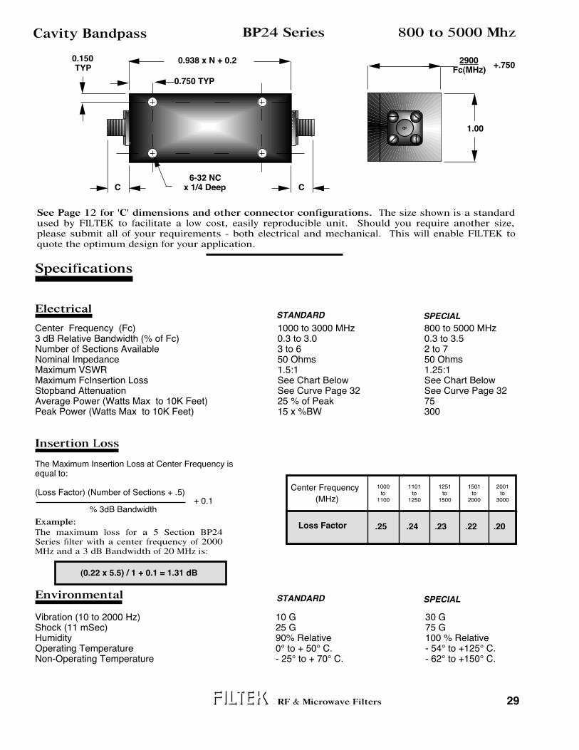
(0.22 x 5.5) / 1 + 0.1 = 1.31 dB
RF & Microwave Filters
Example:
The maximum loss for a 5 Section BP24 Series filter with a center frequency of 2000 MHz and a 3 dB Bandwidth of 20 MHz is:
(Loss Factor) (Number of Sections + .5) + 0.1 % 3dB Bandwidth
Center Frequency
(MHz)
1000to
1100
1101to
1250
1251to
1500
1501to
2000
2001to
3000
Loss Factor .25 .24 .23 .22 .20
Cavity Bandpass BP24 Series 800 to 5000 Mhz
0.750 TYP
CC
0.150 TYP
1.00
2900Fc(MHz)
+.7500.938 x N + 0.2
6-32 NC x 1/4 Deep
Center Frequency (Fc)3 dB Relative Bandwidth (% of Fc)Number of Sections AvailableNominal ImpedanceMaximum VSWRMaximum FcInsertion LossStopband AttenuationAverage Power (Watts Max to 10K Feet)Peak Power (Watts Max to 10K Feet)
1000 to 3000 MHz0.3 to 3.03 to 650 Ohms1.5:1See Chart BelowSee Curve Page 3225 % of Peak15 x %BW
800 to 5000 MHz0.3 to 3.52 to 750 Ohms1.25:1See Chart BelowSee Curve Page 3275300
10 G25 G90% Relative 0° to + 50° C.- 25° to + 70° C.
30 G75 G100 % Relative- 54° to +125° C.- 62° to +150° C.
Vibration (10 to 2000 Hz)Shock (11 mSec)HumidityOperating TemperatureNon-Operating Temperature
See Page 12 for 'C' dimensions and other connector configurations. The size shown is a standard used by FILTEK to facilitate a low cost, easily reproducible unit. Should you require another size, please submit all of your requirements - both electrical and mechanical. This will enable FILTEK to quote the optimum design for your application.

Specifications
Electrical
Environmental
Insertion Loss
The Maximum Insertion Loss at Center Frequency is equal to:
STANDARD SPECIAL
STANDARD SPECIAL
30
(0.43 x 5.5) / 1 + 0.1 = 2.4 dB
RF & Microwave Filters
Example:
The maximum loss for a 5 Section BP25 Series filter with a center frequency of 3000 MHz and a 3 dB Bandwidth of 30 MHz is:
(Loss Factor) (Number of Sections + .5) + 0.1 % 3 dB Bandwidth
Center Frequency
(MHz)
2000to
3000
3001to
4000
4001to
5000
5001to
6000
Loss Factor .44 .43 .42 .41
Cavity Bandpass BP25 Series 1500 to 14000 Mhz
0.500 TYP
CC
0.08 TYP
0.75
3000Fc(MHz)
+ 0.7500.688 x N + 0.38
4-40NC x 1/4 Deep
Center Frequency (Fc)3 dB Relative Bandwidth (% of Fc)Number of Sections AvailableNominal ImpedanceMaximum VSWRMaximum FcInsertion LossStopband AttenuationAverage Power (Watts Max to 10K Feet)Peak Power (Watts Max to 10K Feet)
2000 to 6000 MHz0.3 to 2.03 to 650 Ohms1.5:1See Chart BelowSee Curve Page 3225 % of Peak15 x %BW
1500 to 14000 MHz0.2 to 3.02 to 750 Ohms1.25:1See Chart BelowSee Curve Page 3275300
10 G25 G90% Relative 0° to +50° C.- 25° to +70° C.
30 G75 G100 % Relative- 54° to +125° C.- 62° to +150° C.
Vibration (10 to 2000 Hz)Shock (11 mSec)HumidityOperating TemperatureNon-Operating Temperature
See Page 12 for 'C' dimensions and other connector configurations. The size shown is a standard used by FILTEK to facilitate a low cost, easily reproducible unit. Should you require another size, please submit all of your requirements - both electrical and mechanical. This will enable FILTEK to quote the optimum design for your application.

Specifications
Electrical
Environmental
Insertion Loss
The Maximum Insertion Loss at Center Frequency is equal to:
STANDARD SPECIAL
STANDARD SPECIAL
31
(0.22 x 4.5) / 0.75 + 0.1 = 1.4 dB
RF & Microwave Filters
Example:
The maximum loss for a 4 Section BP26 Series filter with a center frequency of 8000 MHz and a 3 dB Bandwidth of 60 MHz is:
(Loss Factor) (Number of Sections + .5) + 0.1
% 3 dB Bandwidth
Cavity Bandpass BP26 Series 5000 to 18000 Mhz
CC
1.25 Max
8850Fc(MHz)
+ .125 App
Center Frequency (Fc)3 dB Relative Bandwidth (% of Fc)Number of Sections AvailableNominal ImpedanceMaximum VSWRMaximum Fc Insertion LossStopband AttenuationAverage Power (Watts Max to 10K Feet)Peak Power (Watts Max to 10K Feet)
6000 to 12400 MHz0.3 to 1.03 to 450 Ohms1.5:1See Chart BelowSee Curve Page 3210 % of Peak150 x % BW
5000 to 18000 MHz0.1 to 2.02 to 750 Ohms1.25:1See Chart BelowSee Curve Page 322005000
10 G25 G90% Relative 0° to + 50° C.- 25° to +70° C.
30 G75 G100 % Relative- 54° to +125° C.- 54° to +150° C.
Vibration (10 to 2000 Hz)Shock (11 mSec)HumidityOperating TemperatureNon-Operating Temperature
9000 x N Fc(MHz)
+ 0.375
Center Frequency(MHz)
6000to
12400
Loss Factor 0.22
See Page 12 for 'C' dimensions and other connector configurations. The size shown is a standard used by FILTEK to facilitate a low cost, easily reproducible unit. Should you require another size, please submit all of your requirements - both electrical and mechanical. This will enable FILTEK to quote the optimum design for your application.

32 RF & Microwave Filters
Cavity Bandpass FilterStopband Attenuation
The graphs on the following pages define the normal specification limits of attenuation for FILTEK Cavity Bandpass filters. The minimum level of attenuation in dB is shown as a "Number of 3dB Bandwidths from Center Frequency."
The exact relationship is as follows:
1. 3dB bandwidths from center frequency =
Example:
2. Center Frequency = 1000 MHz Minimum 3dB Bandwidth = 10 MHz Number of sections = 4
Find: Minimum attenuation levels at 980 MHz and 1020 MHz.
3dB bandwidths from Fc = (980-1000) / 10 = - 2.0 and (1020-1000) / 10 = + 2.0
The answer can be read directly from the graph. Using the 4 section curve at the point - 2.0 (980 MHz), the minimum level of attenuation is 46 dB; at + 2.0 (1020 MHz), the minimum level of attenuation is 46 dB.
Rejection Frequency (MHz) - Center Frequency (MHz)3 dB Bandwidth (MHz)
20
30
40
50
60
70
10
- 5 - 4 - 3 - 2 - 1 0 + 1 + 2 + 3 + 4 + 5
Att
enu
atio
n (
dB
)
20
30
40
50
60
70
10
2 Sectio
n
4 Sec
tion
5 S
ecti
on
6 S
ectio
n
3 Section
4 Section5
Sectio
n
6 S
ectio
n
Number of 3dB Bandwidths from Fc
3 Sec
tion
2 Section
BP
21
ON
LY
BP
21 O
NL
Y
Atte
nu
atio
n (d
B)

Center Frequency (Fc)3 dB Relative Bandwidth (% of Fc)Number of Sections AvailableNominal ImpedanceMaximum VSWRMaximum Fc Insertion LossStopband AttenuationAverage Power (Watts Max to 10K Feet)Peak Power (Watts Max to 10K Feet)
Environmental
Insertion Loss
STANDARD SPECIAL
33
(.95 x 5.5) / 5 + 0.1 = 1.2dB
Combline Bandpass BP30 Series
RF & Microwave Filters
Cutoff Frequency
(MHz)
1000to
1250
1251to
1500
1501to
2000
2001to
3000
3001to
18000
Loss Factor 2.0 1.7 1.5 1.2 .95
2-56 NC2B x 3/16" Deep
500 to 22500 MHz
.10 TYPICAL
CC
.10TYPICAL
.75
(N x .3) + 1.00 Approx.1450/Fc Mhz + .50
Specifications
ElectricalSTANDARD SPECIAL
1000 to 18000 MHz3 to 303 to 1050 Ohms 1.5:1See Chart BelowSee Curve Page 3610% of Peak10 x % BW
500 to 22500 MHz2 to 703 to 2050 Ohms1.25:1See Chart BelowSee Curve Page 3650100
The Maximum Insertion Loss at Center Frequency isequal to:
Example:
The maximum loss for a 5 Section BP30 Series filter with a center frequency of 7500 MHz and a 3dB Bandwidth of 375 MHz is:
10 G25 G90% Relative 0° to +50° C.-54° to + 85° C.
20 G50 G100 % Relative-54° to +125° C.-62° to +150° C.
Vibration (10 to 2000 Hz)Shock (11 mSec)HumidityOperating TemperatureNon-Operating Temperature
See Page 12 for 'C' dimensions and other connector configurations. The size shown is a standard used by FILTEK to facilitate a low cost, easily reproducible unit. Should you require another size, please submit all of your requirements - both electrical and mechanical. This will enable FILTEK to quote the optimum design for your application.
(Loss Factor) (Number of Sections + .5)+ 0.1
% 3dB Bandwidth

Specifications
Electrical
Environmental
Insertion Loss
STANDARD SPECIAL
STANDARD SPECIAL
34
(1.2 x 10.5) / 15 + 0.1 = .94 dB
RF & Microwave Filters
Center Frequency
(MHz)
1000to
2000
2001to
3000
3001to
4000
4001to
5000
5001to
9000
Loss Factor 1.7 1.2 .95 .85 .80
Interdigital Bandpass 500 to 18000 MHzBP31 Series
.63
2950/Fc (MHz) + .63
C
(0.5 x N) + 1.50 Approx
Center Frequency (Fc)3 dB Relative Bandwidth (% of Fc)Number of Sections AvailableNominal ImpedanceMaximum VSWRMaximum Fc Insertion LossStopband AttenuationAverage Power (Watts Max to 10K Feet)Peak Power (Watts Max to 10K Feet)
1000 to 12000 MHz3 to 303 to 1250 Ohms1.5:1See Chart BelowSee Curve Page 36(3 x % BW) / Loss Factor15 x %BW
500 to 18000 MHz2 to 703 to 2050 Ohms1.25:1See Chart BelowSee Curve Page 361001000
The Maximum Insertion Loss at Center Frequency is equal to:
Example:
The maximum loss for a 10 Section BP31 Series filter with a center frequency of 3000 MHz and a 3 dB Bandwidth of 450 MHz is:
2 G5 G90% Relative 0° to +50° C.-54° to +85° C.
15 G15 G100 % Relative-54° to +125° C.-62° to +150° C.
Vibration (10 to 2000 Hz)Shock (11 mSec)HumidityOperating TemperatureNon-Operating Temperature
See Page 12 for 'C' dimensions and other connector configurations. The size shown is a standard used by FILTEK to facilitate a low cost, easily reproducible unit. Should you require another size, please submit all of your requirements - both electrical and mechanical. This will enable FILTEK to quote the optimum design for your application.
(Loss Factor) (Number of Sections + .5)+ 0.1
% 3dB Bandwidth
Optional Connector Location

Specifications
Electrical
Environmental
Insertion Loss
STANDARD SPECIAL
STANDARD SPECIAL
(2.0 x 5.5) / 10 = 1.1 dB
Miniature Combline BP32 Series
RF & Microwave Filters
Center Frequency
(MHz)
Loss Factor 2.0 1.9 1.8 1.7 1.6
4000to
5000
5001to
6000
6001to
8000
8001to
10000
10001to
12000
(.20 x N) +.20 Approx.0.38
IN / OUT.017 DIA. x .1252 PLACES
3000 to 18000 MHz
35
Center Frequency (Fc)3 dB Relative Bandwidth (% of Fc)Number of Sections AvailableNominal ImpedanceMaximum VSWRMaximum Fc Insertion LossStopband AttenuationAverage Power (Watts Max to 10K Feet)Peak Power (Watts Max to 10K Feet)
4000 to 12000 MHz5 to 203 to 650 Ohms1.5:1See Chart BelowSee Curve Page 36210
3000 to 18000 MHz3 to 303 to 1050 Ohms1.25:1See Chart BelowSee Curve Page 3620100
The Maximum Insertion Loss at Center Frequency is equal to:
Example:The maximum loss for a 5 Section BP32 Series filter with a center frequency of 5000 MHz and a 3 dB Bandwidth of 500 MHz (10%) is:
10 G25 G90% Relative 0° to +50° C.-25° to +75° C.
50 G100 G100 % Relative-54° to +125° C.-62° to +150° C.
Vibration (10 to 2000 Hz)Shock (11 mSec)HumidityOperating TemperatureNon-Operating Temperature
2950Fc (MHz)
+.40
The size shown is a standard used by FILTEK to facilitate a low cost, easily reproducible unit. Should you require another size, please submit all of your requirements - both electrical and mechanical. This will enable FILTEK to quote the optimum design for your application.
(Loss Factor) (Number of Sections + .5)+ 0.1
% 3dB Bandwidth

The graphs on the following pages define the normal specification limits of attenuation for FILTEK Combline and Interdigital Bandpass filters. The minimum level of attenuation in dB is shown as a "Number of 3dB Bandwidths from Center Frequency." Since the filter characteristics vary for differing bandwidths, it is necessary to establish specifications for each bandwidth of filter. The different graphs represent the various 3dB percentage bandwidths. The 3dB percentage bandwidth is defined as follows: 3dB Bandwidth (MHz) x 100 Center Frequency (MHz)
The exact relationship is as follows:
1. 3dB bandwidths from center frequency =
Example:
2. Center Frequency = 5000 MHz Minimum 3 dB Bandwidth = 500 MHz Number of sections = 5
Find: Minimum attenuation levels at 4250 MHz and 5800 MHz.
3 dB bandwidths from Fc = (4250 - 5000) / 500 = - 1.5 and (5800 - 5000) / 30 = + 1.6
As the three dB Bandwidth is exactly 10% of the center frequency, the answer can be read directly from the 10% graph. Using the 5 section curve at the point -1.5 (4250 MHz), the minimum level of attenuation is 40 dB. At + 1.6 (5800 MHz), the minimum level of attenuation is 50 dB.
36 RF & Microwave Filters
Combline and Interdigital BandpassStopband Attenuation
Rejection Frequency (MHz) - Center Frequency (MHz)3dB Bandwidth (MHz)
20
30
40
50
60
70
- 5 - 4 - 3 - 2 - 1 0 + 1 + 2 + 3 + 4 + 5
10 S
ectio
n
Att
en
uati
on
(dB
)
20
30
40
50
60
70
3 Sec
tion
4 S
ecti
on5 S
ecti
on
6 S
ectio
n3 S
ection
4 S
ectio
n
5 S
ec
tion
6 S
ectio
n
10 S
ectio
n
Number of 3dB Bandwidths from Fc
8 S
ecti
on 8
Sectio
n
3 - 5% Bandwidths
Atte
nuatio
n (d
B)

37RF & Microwave Filters
Combline and Interdigital Bandpass Stopband Attenuation
20
30
40
50
60
70- 5 - 4 - 3 - 2 - 1 0 + 1 + 2 + 3 + 4 + 5
8 S
ecti
on
10 S
ecti
on
Att
en
ua
tio
n (
dB
)
20
30
40
50
60
70
3 Sec
tion
4 Sec
tion
5 S
ection
6 S
ecti
on
3 Sectio
n
4 S
ectio
n
5 S
ectio
n
6 S
ectio
n
10 S
ectio
n
Number of 3dB Bandwidths from Fc
8 S
ectio
n
6-10% Bandwidths
20
30
40
50
60
70- 5 - 4 - 3 - 2 - 1 0 + 1 + 2 + 3 + 4 + 5
10 S
ecti
on
Att
en
uati
on
(d
B)
20
30
40
50
60
70
3 Sec
tion
4 Sec
tion
5 S
ection
6 S
ecti
on
3 S
ectio
n
4 S
ectio
n
5 S
ectio
n
6 S
ectio
n
10 S
ectio
n
Number of 3dB Bandwidths from Fc
8 S
ecti
on 8
Sectio
n
11-30% Bandwidths
Atte
nu
atio
n (d
B)
Atte
nu
atio
n (d
B)

Environmental STANDARD SPECIAL
38
Tunable Bandpass BP40 Series 31 to 2000 MHz
Specifications
Electrical
Type 'N' female connectors are standard for this series. See Page 12 for 'C' dimension. The size shown is a standard used by FILTEK to facilitate a low cost, easily reproducible unit. Should you require another size, please submit all of your requirements - both electrical and mechanical. This will enable FILTEK to quote the optimum design for your application. The filters are supplied with a direct reading dial calibrated in frequency to ± 0.5%.
Vibration (10 to 2000 Hz)Shock (11 mSec)HumidityOperating TemperatureNon-Operating Temperature
2 G5 GLab Environment Lab Environment 0° to + 50° C.
5 G10 GLab Environment 0° to + 50° C.- 10° to + 70° C.
Tuning Range % BW(3 dB Rel.)
Fc Insertion Loss (dB Max)3 Section 4 Section 5 Section
31 to 62 MHz
62 to 125 MHz
125 to 250 MHz
250 to 500 MHz
500 to 1000 MHz
1000 to 2000 MHz
Power(Watts)
2% ± 1/2%
2% ± 1/2%
2% ± 1/2%
2% ± 1/2%
2% ± 1/2%
2% ± 1/2%
5% ± 1%
5% ± 1%
5% ± 1%
5% ± 1%
5% ± 1%
5% ± 1%
2.2
1.2
2.2
1.2
2.2
1.0
2.0
0.9
2.0
0.9
2.0
0.9
2.5
1.5
2.5
1.5
2.5
1.2
2.3
1.0
2.3
1.0
2.3
1.0
2.8
1.8
2.8
1.8
2.8
1.5
2.6
1.3
2.6
1.3
2.6
1.3
35
60
35
60
35
60
35
60
35
60
35
60
L (Inches)
5.437
5.437
5.437
5.437
5.437
3.625
W(Inches)
W
C
L 2.81
6570
RF & Microwave Filters
Shape Factor
Sections
3
4
5
30 dB Bandwidth3dB Bandwidth
40 dB Bandwidth3dB Bandwidth
50 dB Bandwidth3dB Bandwidth
3.5 Max
2.8 Max
2.2 Max 3.5 Max
3.5 Max
2.8 Max
N/A
N/A
N/A
3 Section 4 Section 5 Section
5.987
5.987
5.987
5.987
5.987
4.500
7.612
7.612
7.612
7.612
7.612
5.625
9.237
9.237
9.237
9.237
9.237
6.750
Mechanical

Specifications
Electrical
Environmental
Vibration (10 to 2000 Hz)Shock (11 mSec)HumidityOperating TemperatureNon-Operating Temperature
10 G30 G90% Relative 0° to +50° C.-25° to +75° C.
Cutoff Frequency (Fco)Number of Sections AvailableNominal ImpedanceMaximum VSWR (.4 Fco to Fco)Maximum Fco Insertion LossStopband AttenuationAverage Power (Watts Max to 10 K Feet)Peak Power (Watts Max to 10 K Feet)
250 to 4000 MHz3 to 850 Ohms1.5:1See Chart BelowSee Curve Page 453/Loss Factor250
Insertion Loss
The Maximum Insertion Loss in the passband isequal to:
(Loss Factor x Number of Sections) +.05 dB
Example:The maximum loss for a 3 Section LP02 Seriesfilter with a cutoff frequency of 400 MHz is:
100 to 5000 MHz2 to 1275 or 100 Ohms1.25:1See Chart BelowSee Curve Page 455/Loss Factor3000
STANDARD SPECIAL
50 G100 G100 % Relative-25° to +100° C.-54° to +125° C.
STANDARD SPECIAL
39
(.2 x 3) + .05 = 0.65dB
RF & Microwave Filters
Numberof
Sections
3
4
5
6
7
8
Cutoff Frequency (MHz)
2.00
2.75
3.50
4.25
5.00
5.76
1.75
2.25
2.75
3.25
3.75
4.25
1.50
2.00
2.50
3.00
3.50
4.00
2.25
3.00
3.50
4.00
4.50
5.00
1.50
1.75
2.25
2.50
Cutoff Frequency
(MHz)
Loss Factor .22 .21 .20 .18 .17
Tubular Lowpass 100 to 5000 MHzLP02 Series
The approximate length of a FILTEK LP02 series filter can be determined by adding the 'C' dimensions found on page 12 to the 'L' dimension found in the table at the right. Please contact the factory if exact dimensions are required.
The approximate weight is .50 ounce per inch.
C L C
3/8" Dia.
250to
300
301to
350
351to
750
751to
1250
1251to
4000
250to
300
301to
350
351to
750
751to
1250
1251to
4000

Specifications
Electrical
Environmental
Insertion Loss
STANDARD SPECIAL
STANDARD SPECIAL
40
(.2 x 4) + .05 = 0.85dB
Cutoff Frequency
(MHz)
Loss Factor .24 .20 .17 .15 .14
RF & Microwave Filters
Numberof
Sections
3
4
5
6
7
8
Cutoff Frequency (MHz)
3.50
4.50
5.50
6.50
7.50
8.50
2.25
3.00
3.75
3.50
4.00
5.00
2.00
2.50
3.00
3.50
4.00
4.25
1.50
1.75
2.00
2.50
3.00
4.75
1.25
1.50
2.00
2.50
3.00
3.50
Tubular Lowpass LP03 Series 50 to 4000 MHz
The Maximum Insertion Loss in the passband isequal to:
(Loss Factor x Number of Sections) +.05 dB
Example:The maximum loss for a 4 Section LP03 Seriesfilter with a cutoff frequency of 250 MHz is:
Vibration (10 to 2000 Hz)Shock (11 mSec)HumidityOperating TemperatureNon-Operating Temperature
10 G30 G90% Relative 0° to +50° C.-25° to +75° C.
Cutoff Frequency (Fco)Number of Sections AvailableNominal ImpedanceMaximum VSWR (.4 Fco to Fco)Maximum Fco Insertion LossStopband AttenuationAverage Power (Watts Max to 10K Feet)Peak Power (Watts Max to 10K Feet)
100 to 2500 MHz3 to 850 Ohms1.5:1See Chart BelowSee Curve Page 456/Loss Factor500
50 to 4000 MHz2 to 1275 or 100 Ohms1.25:1See Chart BelowSee Curve Page 4512/Loss Factor7500
50 G100 G100 % Relative-25° to +100° C.-54° to +125° C.
The approximate length of a FILTEK LP03 series filter can be determined by adding the 'C' dimensions found on page 12 to the 'L' dimension found in the table at the right. Please contact the factory if exact dimensions are required.
The approximate weight is .75 ounce per inch.
100to
250
201to
400
401to
1000
1001to
1500
1501to
2500
201to
400
401to
1000
1001to
1500
1501to
2500
100to
200
C L C
1/2" Dia.

Specifications
Electrical
Environmental
Insertion Loss
STANDARD SPECIAL
STANDARD SPECIAL
41
(.14 x 4) + .05 = 0.61dB
RF & Microwave Filters
Numberof
Sections
3
4
5
6
7
8
Cutoff Frequency (MHz)
5.50
7.75
10.00
12.75
15.25
18.00
4.50
6.50
8.50
10.00
11.00
12.50
3.50
4.00
4.50
5.75
6.50
7.25
3.25
3.75
4.25
5.50
6.25
7.00
3.00
3.50
4.00
5.00
6.00
6.75
Cutoff Frequency
(MHz)
Loss Factor .16 .15 .14 .13 .12
Tubular Lowpass LP04 Series 30 to 2000 MHz
50to65
66to80
81to
150
151to
1000
1001to
1500
3/4" Dia.
C L C
The approximate length of a FILTEK LP04 series filter can be determined by adding the 'C' dimensions found on page 12 to the 'L' dimension found in the table at the right. Please contact the factory if exact dimensions are required.
The approximate weight is 1.0 ounce per inch.
50to65
66to80
81to
150
151to
1000
1001to
1500
Vibration (10 to 2000 Hz)Shock (11 mSec)HumidityOperating TemperatureNon-Operating Temperature
5 G15 G90% Relative 0° to +50° C.-25° to +75° C.
Cutoff Frequency (Fco)Number of Sections AvailableNominal ImpedanceMaximum VSWR (.4 Fco to Fco)Maximum Fc Insertion LossStopband AttenuationAverage Power (Watts Max to 10K Feet)Peak Power (Watts Max to 10K Feet)
50 to 1500 MHz3 to 850 Ohms1.5:1See Chart BelowSee Curve Page 4510/Loss Factor500
30 to 2000 MHz2 to 1275 or 100 Ohms1.25:1See Chart BelowSee Curve Page 4520/Loss Factor7500
30 G75 G100 % Relative-25° to +100° C.-54° to +125° C.
The Maximum Insertion Loss in the passband isequal to:
(Loss Factor x Number of Sections) +.05 dB
Example:The maximum loss for a 4 Section LP04 Seriesfilter with a cutoff frequency of 100 MHz is:

Specifications
Electrical
Environmental
Insertion Loss
STANDARD SPECIAL
STANDARD SPECIAL
42
(.22 x 3) + .05 = 0.71dB
RF & Microwave Filters
Cutoff Frequency
(MHz)
Loss Factor .26 .25 .24 .23 .22
Lumped Element Lowpass LP11 Series 5 to 500 MHz
10to15
16to20
21to30
31to 50
51to
150
2.38 1.06.06 TYP
.06 TYP
1.00
2-56 NC2Bx 3/16" Deep CC
Vibration (10 to 2000 Hz)Shock (11 mSec)HumidityOperating TemperatureNon-Operating Temperature
10 G30 G90% Relative 0° to + 50° C.-25° to + 85° C.
Cutoff Frequency (Fco)Number of Sections AvailableNominal ImpedanceMaximum VSWR (.4 Fco to Fco)Maximum Fco Insertion LossStopband AttenuationAverage Power (Watts Max to 10K Feet)Peak Power (Watts Max to 10K Feet)
10 to 150 MHz3 to 650 Ohms1.5:1See Chart BelowSee Curve Page 4515
10 to 500 MHz2 to 1075 or 100 Ohms1.25:1See Chart BelowSee Curve Page 451050
50 G100 G100 % Relative-54° to +125° C.-62° to +150° C.
The Maximum Insertion Loss in the passband isequal to:
(Loss Factor x Number of Sections) +.05 dB
Example:The maximum loss for a 3 Section LP11 Seriesfilter with a cutoff frequency of 100 MHz is:
See Page 12 for 'C' dimensions and other connector configurations. The size shown is a standard used by FILTEK to facilitate a low cost, easily reproducible unit. Should you require another size, please submit all of your requirements - both electrical and mechanical. This will enable FILTEK to quote the optimum design for your application.

Specifications
Electrical
Environmental
Insertion Loss
STANDARD SPECIAL
STANDARD SPECIAL
43
(.26 x 3) + .05 = 0.83dB
RF & Microwave Filters
Cutoff Frequency
(MHz)
Loss Factor .42 .36 .32 .26 .24
Lumped Element Lowpass LP12 Series 10 to 5000 MHz
Vibration (10 to 2000 Hz)Shock (11 mSec)HumidityOperating TemperatureNon-Operating Temperature
10 G30 G90% Relative 0° to +50° C.-25° to +75° C.
Cutoff Frequency (Fco)Number of Sections AvailableNominal ImpedanceMaximum VSWR (.4 Fco to Fco)Maximum Fco Insertion LossStopband AttenuationAverage Power (Watts Max to 10K Feet)Peak Power (Watts Max to 10K Feet)
250 to 2500 MHz3 to 550 Ohms1.5:1See Chart BelowSee Curve Page 4515
10 to 5000 MHz2 to 1075 or 100 Ohms1.25:1See Chart BelowSee Curve Page 45525
50 G100 G100 % Relative-54° to +125° C.-62° to +150° C.
The Maximum Insertion Loss in the passband isequal to:
(Loss Factor x Number of Sections) +.05 dB
Example:The maximum loss for a 3 Section LP12 Seriesfilter with a cutoff frequency of 1000 MHz is:
250to
300
301to
400
401to
500
501to
1000
1001to
2500
0
.75
0
0
.218
.436
.062
.375
0
.312
.06
2
.68
8
.017 DIAX .125 LONG6 PLACES
.375
0
.218
.436
.062
.312
0
.156.7
50
.017 DIAX .125 LONG6 PLACES
IN OUT IN OUT
0
MM Configuration LL Configuration
See Page 12 for 'C' dimensions and other connector configurations. The size shown is a standard used by FILTEK to facilitate a low cost, easily reproducible unit. Should you require another size, please submit all of your requirements - both electrical and mechanical. This will enable FILTEK to quote the optimum design for your application.

Specifications
Electrical
Environmental
Insertion Loss
STANDARD SPECIAL
STANDARD SPECIAL
44
(.28 x 3) + .05 = 0.89dB
RF & Microwave Filters
Cutoff Frequency
(MHz)
Loss Factor .44 .38 .34 .28 .26
Lumped Element Lowpass LP13 Series 10 to 5000 MHz
Vibration (10 to 2000 Hz)Shock (11 mSec)HumidityOperating TemperatureNon-Operating Temperature
10 G30 G90% Relative 0° to +50° C.-25° to +75° C.
Cutoff Frequency (Fco)Number of Sections AvailableNominal ImpedanceMaximum VSWR (.4 Fco to Fco)Maximum Fco Insertion LossStopband AttenuationAverage Power (Watts Max to 10K Feet)Peak Power (Watts Max to 10K Feet)
250 to 2500 MHz3 to 550 Ohms1.5:1See Chart BelowSee Curve Page 4515
10 to 5000 MHz2 to 675 or 100 Ohms1.25:1See Chart BelowSee Curve Page 45525
50 G100 G100 % Relative-54° to +125° C.-62° to +150° C.
The Maximum Insertion Loss in the passband isequal to:
(Loss Factor x Number of Sections) +.05 dB
Example:The maximum loss for a 3 Section LP12 Seriesfilter with a cutoff frequency of 1000 MHz is:
.316
.316
.60 DIA
.350
.017/.020 DIA.
.125 TYP
IN/OUT
IN/OUT
250to
301
301to
400
401to
500
501to
1000
1001to
2500
The size shown is a standard used by FILTEK to facilitate a low cost, easily reproducible unit. Should you require another size, please submit all of your requirements - both electrical and mechanical. This will enable FILTEK to quote the optimum design for your application.

45RF & Microwave Filters
Lowpass Filter
The graph below defines the normal specification limits of attenuation for FILTEK Lowpass filters. The minimum level of attenuation in dB is shown as a function of the relative frequency.
a) Fco is defined as the 1.5/1 VSWR cutoff frequency.
b) Relative frequency is the frequency to be attenuated divided by the nominal Fco.
Example: Specify a lowpass filter to pass 1250 MHz and attenuate 1750 MHz by a minimum of 50dB.
1. 1750 MHz is at a relative frequency of 1.4 (1750/1250 = 1.4)
2. Reading from the curve at a relative frequency of 1.4, we find that a five section filter has a normal specification limit of 52dB. Therefore a lowpass filter with five or more sections would be required to meet the 50dB attenuation specification.
Stopband Attenuation
1.0 1.1 1.2 1.3 1.4 1.6 1.8 2.0
10
20
30
40
50
60
70
AT
TE
NU
AT
ION
(d
B)
RELATIVE FREQUENCY (F/Fco)
2 Section
3 Section
4 Section5 Section6 S
ection
7 Section
8 S
ectio
n
9 S
ectio
n
10 S
ectio
n
12 S
ectio
n
10
20
30
40
50
60
2.570

Specifications
Electrical
Environmental
Insertion Loss
STANDARD SPECIAL
STANDARD SPECIAL
46
(0.2 x 3) + 0.05 = 0.7dB
RF & Microwave Filters
2.38 1.06.06 TYP
.06 TYP
1.00
2-56 NC2Bx 3/16" Deep CC
Cutoff Frequency
(MHz)
Loss Factor 0.22 0.21 0.20 0.20 0.20
10to15
16to20
21to30
31to 50
51to
150
Lumped Element Highpass HP11 Series 10 to 450 MHz
Cutoff Frequency (Fco)Number of Sections AvailableNominal ImpedanceMaximum VSWRMaximum Fco Insertion LossStopband AttenuationAverage Power (Watts Max to 10K Feet)Peak Power (Watts Max to 10K Feet)
10 to 150 MHz3 to 650 Ohms1.5:1See Chart BelowSee Curve Page 5015
10 to 450 MHz2 to 1275 or 100 Ohms1.25:1See Chart BelowSee Curve Page 50525
The Maximum Insertion Loss at Cutoff Fre-quency is equal to:
Example:The maximum loss for a 3 Section HP11 Series filter with a cutoff frequency of 30 MHz is:
Loss Factor (Number of Sections) + 0.05
5 G15 G90 % Relative 0° to +50° C.-25° to +75° C.
10 G30 G100 % Relative-54° to +125° C.-62° to +150° C.
Vibration (10 to 2000 Hz)Shock (11 mSec)HumidityOperating TemperatureNon-Operating Temperature
See Page 12 for 'C' dimensions and other connector configurations. The size shown is a standard used by FILTEK to facilitate a low cost, easily reproducible unit. Should you require another size, please submit all of your requirements - both electrical and mechanical. This will enable FILTEK to quote the optimum design for your application.

Specifications
Electrical
Environmental
Insertion Loss
STANDARD SPECIAL
STANDARD SPECIAL
47
(0.50 x 3) + 0.05 = 1.6 dB
RF & Microwave Filters
0
.75
0
0
.218
.436
.062
.375
0
.312
.06
2
.68
8
.017 DIAX .125 LONG6 PLACES
.375
0
.436
.062
.312
0
.156
1.0
00
IN OUT
0
Cutoff Frequency
(MHz)
Loss Factor 0.64 0.56 0.50 0.42 0.37
250to
300
301to
400
401to
500
501to
1000
1001to
2500
Lumped Element Highpass HP12 Series 250 to 3500 MHz
Cutoff Frequency (Fco)Number of Sections AvailableNominal ImpedanceMaximum VSWRMaximum Fco Insertion LossStopband AttenuationAverage Power (Watts Max to 10K Feet)Peak Power (Watts Max to 10K Feet)
300 to 2000 MHz3 to 550 Ohms1.5:1See Chart BelowSee Curve Page 5015
250 to 3500 MHz2 to 875 or 100 Ohms1.25:1See Chart BelowSee Curve Page 50525
The Maximum Insertion Loss at Cutoff Fre-quency is equal to:
Example:The maximum loss for a 3 Section HP12 Series filter with a cottoff frequency of 500 MHz is:
Loss Factor (Number of Sections) + 0.05
5 G15 G90 % Relative 0° to +50° C.- 25° to + 75° C.
10 G30 G100 % Relative- 54° to +125° C.- 62° to +150° C.
Vibration (10 to 2000 Hz)Shock (11 mSec)HumidityOperating TemperatureNon-Operating Temperature
.218
C.9
38
.06
2
0-80NFx 3/16" DEEP
MM Configuration AA Configuration
See Page 12 for 'C' dimensions and other connector configurations. The size shown is a standard used by FILTEK to facilitate a low cost, easily reproducible unit. Should you require another size, please submit all of your requirements - both electrical and mechanical. This will enable FILTEK to quote the optimum design for your application.

Specifications
Electrical
Environmental
Insertion Loss
STANDARD SPECIAL
STANDARD SPECIAL
48
(0.50 x 3) + 0.05 = 1.6 dB
RF & Microwave Filters
.316
.316.60 DIA
.350
.017/.020 DIA.
.125 TYP
IN/OUT
IN/OUT
Cutoff Frequency
(MHz)
Loss Factor 0.64 0.56 0.50 0.42 0.36
250to
301
301to
400
401to
500
501to
1000
1001to
2500
Lumped Element Highpass HP13 Series 250 to 3500 MHz
Cutoff Frequency (Fco)Number of Sections AvailableNominal ImpedanceMaximum VSWRMaximum Fco Insertion LossStopband AttenuationAverage Power (Watts Max to 10K Feet)Peak Power (Watts Max to 10K Feet)
300 to 2000 MHz3 or 450 Ohms1.5:1See Chart BelowSee Curve Page 5015
250 to 3500 MHz2 to 575 or 100 Ohms1.25:1See Chart BelowSee Curve Page 50525
The Maximum Insertion Loss at Cutoff Fre-quency is equal to:
Example:The maximum loss for a 3 Section HP13 Series filter with a cutoff frequency of 500 MHz is:
Loss Factor (Number of Sections) + 0.05)
5 G15 G90% Relative 0° to +50° C.-25° to + 75° C.
10 G30 G100 % Relative-54° to +125° C.-62° to +150° C.
Vibration (10 to 2000 Hz)Shock (11 mSec)HumidityOperating TemperatureNon-Operating Temperature
The size shown is a standard used by FILTEK to facilitate a low cost, easily reproducible unit. Should you require another size, please submit all of your requirements - both electrical and mechanical. This will enable FILTEK to quote the optimum design for your application.

Specifications
Electrical
Environmental
Insertion Loss
STANDARD SPECIAL
STANDARD SPECIAL
49
(0.24 x 4) + 0.05 = 1.0 dB
RF & Microwave Filters
Cutoff Frequency
(MHz)
Loss Factor .24 .23 .22
4000to
5000
5001to
6000
6001to
10000
Suspended Substrate Highpass HP35 Series 4000 to 10000 MHz
Cutoff Frequency (Fco)Number of Sections AvailableNominal ImpedanceMaximum VSWRMaximum Fco Insertion LossStopband AttenuationAverage Power (Watts Max to 10 K Feet)Peak Power (Watts Max to 10 K Feet)
No Standard ModelContact Filtek Salesfor quote
4000 to 10000 MHz2 to 650 Ohms1.5:1See Chart BelowSee Curve Page 50450
The Maximum Insertion Loss at Cutoff Fre-quency is equal to:
Example:The maximum loss for a 4 Section HP35 Series filter with a cutoff frequency of 4500 MHz is:
Loss Factor (Number of Sections) + 0.05
5 G15 G90% Relative 0° to +50° C.- 25° to +75° C.
30 G75 G100 % Relative- 54° to +125° C.- 62° to +150° C.
Vibration (10 to 2000 Hz)Shock (11 mSec)HumidityOperating TemperatureNon-Operating Temperature
C .50.75 + (No. Sections x .38) Approx.
.75 +
(5900/F
co
)A
pp
rox
See Page 12 for 'C' dimensions and other connector configurations. The size shown is a standard used by FILTEK to facilitate a low cost, easily reproducible unit. Should you require another size, please submit all of your requirements - both electrical and mechanical. This will enable FILTEK to quote the optimum design for your application.

50 RF & Microwave Filters
Highpass Filter
The graph below defines the normal specification limits of attenuation for FILTEK highpass filters. The minimum level of attenuation in dB is shown as a function of the relative frequency.
a) Fco is defined as the 1.5/1 VSWR cutoff frequency.
b) Relative frequency is the nominal Fco divided by the frequency to be attenuated.
Example: Specify a Highpass filter to pass 30 MHz and attenuate 21 MHz a minimum of 50 dB.
1. 21 MHz is at a relative frequency of 1.43 (30/21 = 1.43)
2. Reading from the curve at a relative frequency of 1.43, we find that a five section filter has a normal specification limit of 54 dB. Therefore a highpass filter with five or more sections would be required to meet the 50 dB attenuation specification.
Stopband Attenuation
10
20
AT
TE
NU
AT
ION
(d
B)
RELATIVE FREQUENCY (Fco/F)
1.01.11.21.31.41.61.82.0
30
40
50
60
70
2 Sectio
n
3 Secti
on
4 Sect
ion
5 Sec
tion
6 Sec
tion
7 Sec
tion
8 S
ect
ion
9 S
ect
ion
10 S
ect
ion
12 S
ection
10
20
30
40
50
60
70
AT
TE
NU
AT
ION
(d
B)
2.5

Attenuation
40
30
20
10
40 dB Bandwidth
3 dB Bandwidth
Specifications
Electrical
Environmental
STANDARD SPECIAL
STANDARD SPECIAL
51RF & Microwave Filters
2.38 1.06.06 TYP
.06 TYP
1.00
2-56 NC2Bx 3/16" Deep CC
Lumped Element Bandreject BR11 Series 10 to 150 MHz
Center Frequency (Fc)3dB Relative Bandwidth (% of Fc)Number of Sections AvailableNominal ImpedanceMaximum VSWRMaximum Insertion Loss (± 20% Fc)40 dB/ 3 dB Form FactorNotch Attenuation (Ultimate)Input Power (Watts Max to 10K Feet)
10 to 100 MHz5 to 20450 Ohms1.5:11 dB1:450 dB Typ.1
10 to 150 MHz3 to 302 to 650 Ohms1.2:11 dBContact FiltekContact Filtek5
5 G5 G90 % Relative 0° to + 50° C.- 25° to + 75° C.
15 G30 G100 % Relative-54° to +100° C.-62° to +125° C.
Vibration (10 to 2000 Hz)Shock (11 mSec)HumidityOperating TemperatureNon-Operating Temperature
See Page 12 for 'C' dimensions and other connector configurations. The size shown is a standard used by FILTEK to facilitate a low cost, easily reproducible unit. Should you require another size, please submit all of your requirements - both electrical and mechanical. This will enable FILTEK to quote the optimum design for your application.
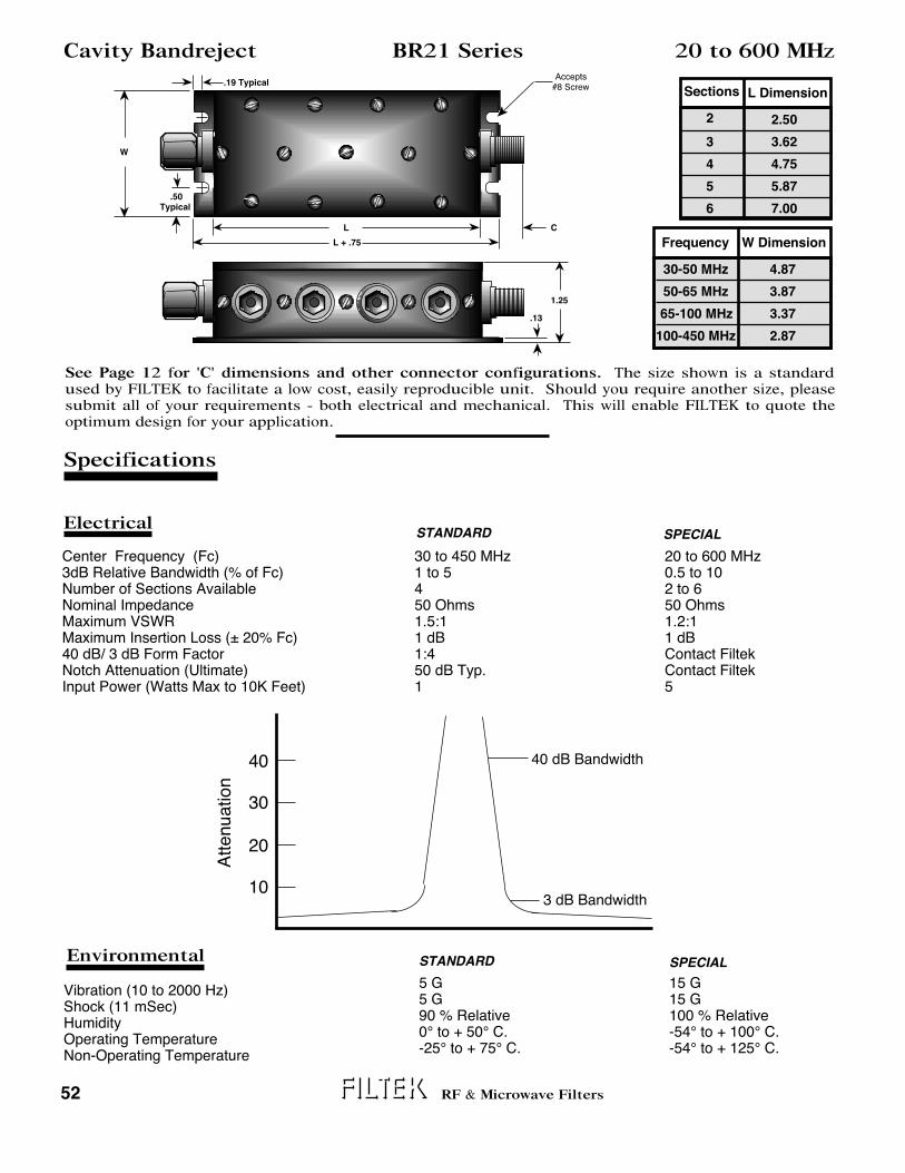
Specifications
Electrical
Environmental
STANDARD SPECIAL
STANDARD SPECIAL
52 RF & Microwave Filters
Cavity Bandreject BR21 Series 20 to 600 MHz
.50Typical
L
L + .75
C
.13
1.25
W
Sections L Dimension
2
3
4
5
6
2.50
3.62
4.75
5.87
7.00
Frequency W Dimension
30-50 MHz
50-65 MHz
65-100 MHz
100-450 MHz
4.87
3.87
3.37
2.87
Vibration (10 to 2000 Hz)Shock (11 mSec)HumidityOperating TemperatureNon-Operating Temperature
30 to 450 MHz1 to 5450 Ohms1.5:11 dB1:450 dB Typ.1
20 to 600 MHz0.5 to 102 to 650 Ohms1.2:11 dBContact FiltekContact Filtek5
5 G5 G90 % Relative0° to + 50° C.-25° to + 75° C.
15 G15 G100 % Relative-54° to + 100° C.-54° to + 125° C.
Attenuation
40
30
20
10
40 dB Bandwidth
3 dB Bandwidth
Center Frequency (Fc)3dB Relative Bandwidth (% of Fc)Number of Sections AvailableNominal ImpedanceMaximum VSWRMaximum Insertion Loss (± 20% Fc)40 dB/ 3 dB Form FactorNotch Attenuation (Ultimate)Input Power (Watts Max to 10K Feet)
Accepts#8 Screw
.19 Typical
See Page 12 for 'C' dimensions and other connector configurations. The size shown is a standard used by FILTEK to facilitate a low cost, easily reproducible unit. Should you require another size, please submit all of your requirements - both electrical and mechanical. This will enable FILTEK to quote the optimum design for your application.

Specifications
Electrical
Environmental
STANDARD SPECIAL
STANDARD SPECIAL
53RF & Microwave Filters
Cavity Bandreject BR22 Series 250 to 2000 MHz
.50 TYPICAL
L
L + .75
C
.13
1.25
W
Sections L Dimension
2
3
4
5
6
2.50
3.62
4.75
5.87
7.00
Frequency W Dimension
400-600 MHz
600-900 MHz
900-1500 MHz
5.87
4.87
3.87
Vibration (10 to 2000 Hz)Shock (11 mSec)HumidityOperating TemperatureNon-Operating Temperature
400 to 1500 MHz1 to 5450 Ohms1.5:11 dB1:450 dB Typ.1
250 to 2000 MHz0.5 to 102 to 650 Ohms1.2:11 dBContact FiltekContact Filtek5
5 G5 G90 % Relative0° to + 50° C.-25° to + 75° C.
15 G15 G100 % Relative-54° to + 100° C.-54° to + 125° C.
Attenuation
40
30
20
10
40 dB Bandwidth
3 dB Bandwidth
Center Frequency (Fc)3dB Relative Bandwidth (% of Fc)Number of Sections AvailableNominal ImpedanceMaximum VSWRMaximum Insertion Loss (± 20% Fc)40 dB/ 3 dB Form FactorNotch Attenuation (Ultimate)Input Power (Watts Max to 10K Feet)
Accepts#8 Screw
.19 TYPICAL
See Page 12 for 'C' dimensions and other connector configurations. The size shown is a standard used by FILTEK to facilitate a low cost, easily reproducible unit. Should you require another size, please submit all of your requirements - both electrical and mechanical. This will enable FILTEK to quote the optimum design for your application.

Environmental STANDARD SPECIAL
54
Cavity Bandreject BR30 Series
RF & Microwave Filters
2-56 NC2B x 3/16" Deep
2000 to 12000 MHz
0.10TYP
CC
0.10TYP
0.75
Specifications
ElectricalSTANDARD SPECIAL
2500 to 8000 MHz1 to 5450 Ohms1.5:11 dB1:450 dB Typ.5
2000 to 12000 MHz0.5 to 102 to 650 Ohms1.2:11 dBContact FiltekContact Filtek20
10 G25 G90% Relative 0° to +50° C.-25° to + 75° C.
20 G50 G100 % Relative-54° to +125° C.-62° to +150° C.
Vibration (10 to 2000 Hz)Shock (11 mSec)HumidityOperating TemperatureNon-Operating Temperature
Attenuation
40
30
20
10
40 dB Bandwidth
3 dB Bandwidth
Center Frequency (Fc)3dB Relative Bandwidth (% of Fc)Number of Sections AvailableNominal ImpedanceMaximum VSWRMaximum Insertion Loss (± 20% Fc)40 dB/ 3 dB Form FactorNotch Attenuation (Ultimate)Input Power (Watts Max to 10K Feet)
2950Fc(MHz)
+1.00
Approx.
2950Fc(MHz)
x N +1.00
Approx.
See Page 12 for 'C' dimensions and other connector configurations. The size shown is a standard used by FILTEK to facilitate a low cost, easily reproducible unit. Should you require another size, please submit all of your requirements - both electrical and mechanical. This will enable FILTEK to quote the optimum design for your application.

Type 'N' Female connectors are standard for this series. See Page 12 for 'C' dimension. The size shown is a standard used by FILTEK to facilitate a low cost, easily reproducible unit. Should you require another size, please submit all of your requirements - both electrical and mechanical. This will enable FILTEK to quote the optimum design for your application. Tunable Bandreject filters are supplied with a direct reading dial calibrated in frequency to ± 0.5%.
Environmental STANDARD SPECIAL
55
Tunable Bandreject BR40 Series
RF & Microwave Filters
31 to 1000 MHz
Specifications
ElectricalSTANDARD
See ChartSee Chart40 kHz Minimum350 Ohms1.5:11 dB5
2 G5 GLab Environment Lab Environment 0° to + 50° C.
5 G10 GLab Environment 0° to + 50° C.- 10° to + 70° C.
Vibration (10 to 2000 Hz)Shock (11 mSec)HumidityOperating TemperatureNon-Operating Temperature
Attenuation
35
30
20
10
35 dB Bandwidth
1 dB Bandwidth
Passband and Tuning Range1dB Bandwidth Nominal35 dB BandwidthNumber of Sections AvailableNominal ImpedanceMaximum VSWR (Passband)Maximum Insertion Loss (Passband)Maximum Input Power (Watts)
Frequency
Passband andTuning Range
31 to 62 MHz
62 to 125 MHz
125 to 250 MHz
250 to 500 MHz
500 to 1000 MHz
1 dB BandwidthNominal
2.5 MHz
3.5 MHz
5.0 MHz
10 MHz
20 MHz
5.44
C
7.61 2.81
6570

56 RF & Microwave Filters
Notes

FILTEK
4410-A Hawkins St. NE
Albuquerque NM 87109
Phone (505) 345-1486 • Fax (928) 776-4208
e-mail: [email protected]
Internet: www.filtekfilters.com


