H U A J I A N G A O and JAMES R. R I C E Division of Applied Sciences, Harvard University, Cambridge, MA 02138, USA
Received 16 May 1986; accepted in revised form 28 December 1986
Abstract
In this paper we apply the method developed by Rice [1], of solving for the elastic field of a crack with a front perturbed from some reference shape, to solve the elasticity problems of somewhat circular planar tensile cracks under arbitrary load distributions. The method is based on a known solution for the stress intensity factor along a circular crack due to a pair of wedge-opening point forces on its surfaces. A full solution, accurate to first order in the deviation from a circular shape, is derived for the stress intensity factor and the crack opening displacement distributions. The results of a perturbation in a harmonic wave form suggest that a circular crack, under axially symmetric loading, can be configurationaUy unstable (not grow as a circle), for loadings that increase in intensity with distance from the center. Circular cracks with harmonic shape perturbations are found to have the same form of variation of the stress intensity factor with arc length along the crack edge (to first order accuracy) as found in previous work for a half plane crack. As a test case for the perturbation solution, an elliptical planar tensile crack under uniform tension is viewed as being perturbed from a circular crack. Results derived from the perturbation formulae through numerical evaluation are compared with the exact solutions existing in the literature. The perturbation results show a very good match with the exact solutions even when the semi-axis lengths of the elliptical crack differ by a factor of two (and by as much as a factor of three when special choices of the reference circular crack location are made). This suggests that the perturbation procedure presented here, while theoretically exact only to first order, can be used to produce acceptable results for some planar cracks whose shapes deviate appreciably from a circle.
1. Introduction
We study in this paper p lanar tensile cracks whose tips lie along arcs that are slightly distorted
f rom circles. Of par t icular interest is how the dis t r ibut ions of the stress in tensi ty factor and the
crack face opening displacement change to the first order of accuracy when the front of an
arbitrari ly loaded crack is per turbed from a circular shape. A full solut ion for these quanti t ies is given in detail.
The method that we use, developed by Rice [1] to solve for the elastic field of a crack with a
front per turbed from some reference geometry, can be carried out at once if a certain solut ion
is known for a crack of that reference geometry. For tensile cracks this is the solut ion for the
stress in tensi ty factor d is t r ibut ion along the reference crack front due to a pair of wedging forces acting to open it at an arbi t rary locat ion on its surfaces. For tunate ly , the requisite point force solut ion can be developed from the work of Ga l in [2] for an in terna l circular crack in an
inf ini te body. It is given by Tada et al. [3] and Cherepanov [4]. Rice [1] applied his method to the half-plane crack in an infini te body. Us ing the point force
solut ion for that case he calculated the crack surface displacement dis tr ibut ion, exact to first order in the per tu rba t ion of the crack front locat ion from a reference straight l ine (he also gave a direct ab ini t io first order solut ion for the elastic field of the per turbed crack). He further derived an expression for the stress in tensi ty factor K along such a non-s t ra ight crack front (again exact to first order) and this led to a discussion of the wavy crack front problem, mot ivated by the study of the same problem by Meade and Keer [5].
Our work here is based on the following result. Consider that an inf ini te three d imens ional elastic solid contains a p lanar crack with smooth b o u n d i n g contour c along the crack front. We
156 H. Gao and J.R. Rice
assume that the solid is homogeneous, isotropic, symmetric about the crack plane, and subjected to a loading system consisting of some distribution of fixed forces that induce 'mode 1' tension along the crack front. A Cartesian coordinate system is attached so that the crack plane lies on y = 0 (Fig. 1). In this circumstance Rice [1] showed that the variation in crack opening displacement Au(x, z) at location x, z when crack front position is altered by 8a(s) in presence of the fixed load system is
to first order in 6a(s), where K°(s) is the intensity factor distribution induced along the crack front by the load system and k(s; x, z) is the intensity factor which would be induced at arc length position s along the crack front by a unit wedging point force pair opening the crack at location x, z. Here the intensity factor K is defined so that K / ~ is the asymptotic form of the tensile stress on the prolongation of the crack plane, at small distance e ahead of the crack tip.
2. Crack opening displacements Now we choose our reference crack geometry as an internal circular crack of radius a in an infinite body. Using (1) and noting that in this case s ~ aO' (Fig. 1), and adopting polar coordinates,
8[ku(r, O)] = 2 (1 - v 2 ) 2~K°( r, e a£ O')k(O'; O)Sa(O') dO' (2)
where K° (0 ' ) is the intensity factor distribution along the circular crack front under the given load system and k(O'; r, O) is the intensity factor that would be induced at position O' along the circular front by a unit pair of wedging forces at r, 0. To emphasize their dependence on the radius of the circular crack, we adopt the following notations for various quantities when they refer to a perfectly circular crack with radius a,
K°(O ') - - 'K°[0 ' ; a]
k(O'; r, O)= k(O'; r, O; a) (3)
Au(r, O)= Au°[r, O; a]
l
6a(O' ~ ~ O ' a ( O )
\ ircular front
Fig. 1. S o m e w h a t c i r cu la r c r a c k o n y = 0 in a n inf in i te e last ic body . R e f e r e n c e c i r cu la r c r a c k f r o n t r = a ( 0 ) cen t e r ed
o n (0, 0); O' deno tes l oca t ion a long ac tua l f ron t a n d 8a(O') deno te s a d v a n c e o f c r a c k f r o n t l o c a t i o n in the p l a n e y = 0.
Somewhat circular tensile cracks 157
If we consider a uniform 8a(O') = 8a along the crack front and divide both sides of (2) by 8a, then let 8a -~ 0,
Noting the fact that the 2xu°[a, 0; a] = 0 (crack closes at edges), by integrating on the crack size variable a ' from r to a (integrate over the whole crack development history) we therefore obtain
Au°[r, 0; a] = 2 (1 E u2) foZTrLaKo[O, a']k(O'; r, O; a')a' d a ' dO' (5)
where by superposition, i
K ° [ 0 ' ; a ' ] = fo2~foak(O'; P, ~; a ' ) p ( p , ~)p dp d~ (6)
when the given loading consists of some distribution of normal pressure p(r, O) on the crack faces. As is well known, the problem of general tensile loading can be described in this way when p(r, O) is equated to the tensile stress which the general loading would induce at r, 0 in the absence of a crack. The stress intensity factor k(O'; r, O; a) in this case is given as [3,4].
~(a : -- r:)/a~r 3 k(O'; r, O; a ) = (7)
a 2 + r 2 - 2ar cos(O-- 0 ' )
Combining (7), (6) and (5), we are able to present the following general formula for the crack opening displacement for circular cracks,
o; a ] : 2 f°f °F°f a' E ~ 3 Jr Jo Jo J0
~ - r 2 ~ - p = p ( p , O)pdpdOdO' da' X [a,2+rZ_2a,rcos(O_O,)][a,Z+p2_2a,pcos(ep_O,) ] . (8)
This is reduced to a simpler form in Appendix A.; see (A-l), (A-3), (A-9) and (A-11). Now let us consider a slightly non-circular crack whose tip is located at r = a(O), where the
function a(O) differs modestly from a constant. For purposes of calculating the opening Au(r, O) along the ray at any particular angle 0, we shall take the reference (unperturbed) crack front to be a circle of radius equal to a(O). We then are able to let r approach simultaneously both the reference front and the actual perturbed front. This, as described in earlier papers [1,6,7], is necessary to retain the correct asymptotic behavior near the crack front as is crucial for the calculation of the stress intensity factor along the perturbed crack front.
We can then interpret 8a(0 ' ) as a(O') - a(O) in (2) and identify a, as it appears elsewhere in that equation, as a (0). Thus
0 t t 2 2 2(1--p 2) f2•K°[0_! a(O)]a_(O)[a!O')_-a(O_)]~/a(O)'-r_ - e J0 ~ [ a ( 0 ) 2 + r 2 - 2 a ( 0 ) / c o s ( 0 ' - 0 ) ] d0 ' (9)
where 8[Au(r, 0)] is the variation in crack opening displacement at location r, 0 when the crack front location is changed from the reference circle of radius equal to a(O) to the slightly
158 H. Gao and J.R. Rice
non-circular perturbed shape. Of course, the expression is accurate to first order in the deviation a(O') - a(O) from circularity. To this same order of accuracy we may rewrite (9) as
8[Au(r, 0)] =2 (1 T_v a) [2,~[a(O')Ko[O, ; a']k(O'; r, O; a')a' da ' d0' (10) • 'o ~a(O)
and this is usefut for the next step of writing a compact formula for the total opening displacement. Indeed, if we combine (10) with (5), the total crack opening is
hu( r , O ) = A u ° [ r , O; a(O)] + 8 [ h u ( r , 0)1
(1 T -p2) fo2erfra(o')K°[O'; a'lk(O'; r, O; a ' ) a ' da ' dO'. (11) 2
This provides a general formula to calculate the crack opening displacement precise to first order for any somewhat circular crack subjected to general tensile loading; K°[O'; a'] can be calculated from (6) for an arbitrary load distribution. This expression is also discussed further in Appendix A.
It may be noted that for a given somewhat circular crack, the location of the center (at which we say r = 0) is somewhat arbitrary. We study the effect and optimization of this center location in a later section.
3. Stress intens i ty factors
The stress intensity factor is related to the relative opening displacement by the asymptotic formula, that is, as r --+ a = a (0 ) ,
8(1 - ~ ) [i( ,~/~" [ 1 ] t v 2~ +O-(a-r)3/~- " Au(r , 0) (12)
The same relation applies between 8[hu(r, 0)] and 8K(0), the first order variation of intensity factor, where again the variations are from the reference circular crack, of radius equal to a(O), to the perturbed crack. Thus combining (12) and (9),
aK(O)= ~4-~ r+a(o)lim f02~rK0[0'; a(O)]a (O)[a (O ' ) - -a (O)] (a (O) + r ~ ((d~ [ a (0)-~ + r2 7 2--~ ~-)7 c~s(~7-£; ~ dO'. (13)
When r --+ a(O),
lira [ a ( O ) 2 + r 2 - 2 a ( O ) r c o s ( O ' - o ) l = 4 a ( O ) 2 s i n 2 ( ~ 2 ~ - ) . r---~a(O) We see that if we directly let r --+ a(O) in (13) the integral is a singular intergral. The limit exists a s
at any point 0 for which da(O)/dO exists. Here the "PV" denotes the principle value in the Cauchy sense.
f0 2'~ f 0 ° ~ + Equation (14) can be proved as follows: Breaking the integral in (13) into 0 + n f J0--n
f/ + the + part, when letting r ~ a- and then ~/-+ 0, gives the "PV" term,
Somewhat circular tensile cracks 159
whereas the f0+n term becomes s O - ~ 1
a(O)[ lim fo+n K___~°[O~';_a_(O_)][a(O')_-a(O_____)] d0 '} . 2~ [r--,a(o:)Jo-n a(O)2+ r 2 - 2ra(O) c o s ( 0 ' - 0 )
The bracketed term becomes, making the variable change t = O' - 0 and letting sin2(t/2) - t2/4,
lim f~ K°[ t+O; a_(O_)][_a(_t+_O_)-a(O)] at. r---~a(O) J - rt (a -- r) 2 + art 2
Note that the numerator of the integrand could be expanded as follows:
K ° [ t + 0; a(0)] [ a ( t + 0) - a(0)] = tK°[O; a(0)] d%(00) + O(t2),
where the neglected terms, of order t 2 when da2(O)/dO 2 exists, will satisfy [O(t 2) I < q t2 on I t [ < 7/ for some constant q > 0. Now observing that
f n t dt = 0 -0 (a - r) 2 + art 2
due to the oddness of the integrand, and that
f ~ t 2 ~n t 2 2~/ dt<j_ a ~ t 2 d t = - - ~ O a s ~ O , -o (a - r) 2 + art 2 n ar
we see that the fo+n term in (13) vanishes in the appropriate limits, and this completes our J0-~
proof of (14). It is not necessary to assume that d2a(O)/dO 2 exists and we could analogously prove (14) if
we assume only that da(O)/dO is Holder continuous, i.e.,
Ida(0 + t)/dO - da(O)/dO I < el tl ~
for some constant c > 0 and 0 < a ~< 1. Note that the actual stress intensity factor for the perturbed crack geometry is K(O)=
K°[0; a(0)] + 8K(O). Therefore,
1 pvf2,~K°[O'; a (O)][a (O ' ) /a (O) - 11 K(O)=K°[O; a(O)] +-g-g~ Jo s-:mSn2[~-0--_0- ~ dO' (15)
to first order accuracy for an arbitrary somewhat circular crack, where the function K°[0; a] is calculated as in (6 and 7).
4. General axi-symmetrical loading and uniform far field loading
Under general axi-symmetrical loading, i.e. p(r, O) =p(r) , . (6) and (5) become,
K°[O' ; a l = f 2 ~ f a P ( r ) ~ - r 2 ,0 Jo ~r3a[a 2 + r 2 - 2 a r c o s ( O - O ' ) ]
r dr dO
2 fa p ( r ) r dr (16) ¢gS Jo
160 H. Gao and J.R. Rice
Au°[r , O; a] = 2 (1 --E/, 2) [2~fa K°[_0'; a£ ] t.._~a t2-- r 2 So 6 ~/7~a, [a,2 + r2_ 2a,r cos(O_O,)] l
da' dO'
. 8 ( 1 - / 2 ) f a 1 fa" P(P)O Jr J0 do da ' .
-- -qT"T- a ~ _ r 2 . ~/a,202 (17)
Notice that both K°[0; a] and hu°[r, 0; a] are independent of 0 as expected in this case. Denoting them by K°[a] and Au°[r; a] as a shorthand in the axi-symmetrical case, (11) and (15) become in this case,
2,~ a ( O ) [ a ( O ' ) - a(0)] dO' (18) f x So a(O) 2 + r 2 - 2ra(O) c o s ( O ' - O)
1 r2,~[a(O')/a(O)- l ] .d0 ,} (19) K(O)= K°[a(O)]{1 +-gTeVJo sT~[--~,-_~)~ where K°[a(O)] and Au°[r; a(0)] are given by (16) and (17) with a replaced by a(O).
Under uniform pressure loading equivalent to far field tensile stress o, i.e. p(r)= o, (16) and (17) can be further simplified as
K° [0 ' ; a] = 2 o ~ (16') q7
Au°[r, O; a] 8(1_-/'2) 0 " ~ -- r 2 (17') rrE
The above formulae are also listed in the literature (e.g. [3]). In addition, (18) and (19) can be written as
Au(r, O) 1_1_f2~ a(O)[a(O') - a(O)] 8(1 E- i,2) o~a(O) 2 _ r 2 1 + 2vr J0 a(O) 2 + r 2 - 2ra(O) c o s ( O ' - O)
Note that an important location is r = 0 where we should get a unique Au(0, 0) (indepen- dent of 0); otherwise continuity is violated. Letting r ~ 0 in (18'),
1 Au(0, 0 ) - 8 ( 1 - p 2 ) ° { ~ f o 2 ~ r a ( o ' ) E d0 '} . (20)
Indeed, it satisfies the continuity condition.
5. Harmonic wave form perturbation
Now consider a crack front along r = a(O) with
a(O) = a o + A e in° (21)
where a 0 is a real constant, n is a positive integer, A is a constant (possibly complex) and I A I/a o << 1. The term A e in° should be thought of as its real part. Later the real part of the
response should be taken correspondingly.
Somewhat circular tensile cracks 161
It is also assumed for convenience that the loading is axi-symmetric so that the stress intensity factors induced along the reference crack front are uniform, i.e. K°[O'; a] = K°[a] . Substituting (21) into (19), and denoting the 'PV' integral in (19) by I,
I=PVfo2~[a(O')/a(O)-l]~n2- ~ - -~oein°PVfo 2~ [ ein(°'-°)-l] 0)72 ~ dO '= (22) si t 7 7)721 dO'
to first order. Letting z = e i(°'-°), we transform this integral into the complex plane z on a contour
I z] = 1 so that
I= 4A einO vfl zn-~2 dz ao ~ P z ]= l ( z --
The integrand has a simple pole at z = 1 and is analytic elsewhere, hence
4A e i~° [ z~---1 ] = - 4 ~ r n A e i~°. (23) I = a o ~ r r iRes_ ( z - 1) 2 J[z=l a °
Combining (23) and (19) and keeping only the first order term in A,
[ d K ° n ] ein o K = K ° + i d a ° 2a 0K ° A (24)
where K ° = K°[ao]. Recall that we are to interpret A e i~° as its real part. Notice that the number of full harmonic waves on the whole periphery is n so that the
wavelength is X = 2rrao/n and (24) can be recast as
Ida° ] ei ° Ida° ] da0 K = K ° + xK ° A = + xK ° A (s=aoO). (25)
The form of the above formula remains the same no matter what is the radius of the circular crack. The fact that the case when the radius a ~ oc corresponds to the case of the half-plane crack explains why (25) shows an exact correspondence to the half-plane crack formula given by Rice (see (31) of [1]).
It is worth pointing out that the fact that (25) does not depend explicitly on the radius of the crack shows the intrinsic relation of the circular cracks and the half-plane crack. The discussion of half-plane crack stability [1] has an exact correspondence in the case of a penny-shaped crack. Specifically, the circular crack can be said to be configurationally stable during subcritical crack growth (by fatigue or stress corrosion) if K is decreased from K°[a0] when a(O) exceeds a 0 and increased when a(O) is less than a 0. This stability condition is based on the assumption that the growth rate increases with K. Considering harmonic perturbations, the requirement for stability will be met when the bracketed term in (25) is negative, which means that there exists a critical wavelength )t c = rrK°/(dK°/dao) above which the perturbation will tend to grow and below which it will diminish.
Consider the case, for example, when a circular crack of radius equal to a is under uniform remote stress o,
K0 = 2o #a -" qr
By simple algebraic manipulation we get
o d K ° Xc=vrK / ( ~ 7 - a ) = 2rra = periphery.
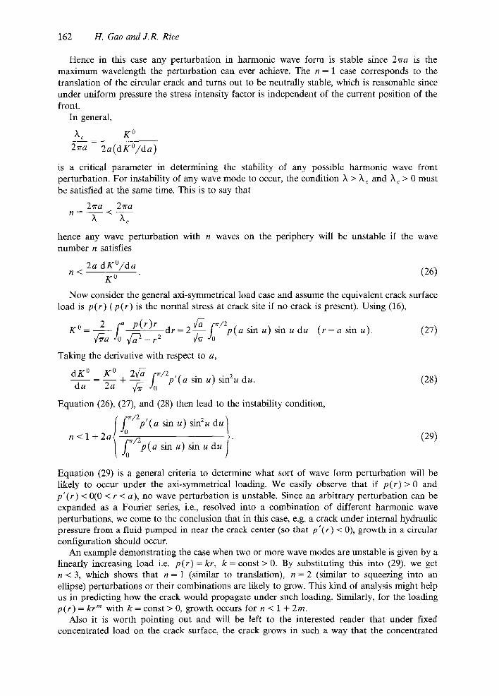
162 11. Gao and J.R. Rice
Hence in this case any perturbation in harmonic wave form is stable since 27ra is the maximum wavelength the perturbation can ever achieve. The n = 1 case corresponds to the translation of the circular crack and turns out to be neutrally stable, which is reasonable since under uniform pressure the stress intensity factor is independent of the current position of the front.
In general,
X~ K °
2~ra 2a(dKO/da)
is a critical parameter in determining the stability of any possible harmonic wave front perturbation. For instability of any wave mode to occur, the condition h > X c and ?to > 0 must be satisfied at the same time. This is to say that
2Tra 27ra / , / = < - -
h X~
hence any wave perturbation with n waves on the periphery will be unstable if the wave number n satisfies
2a dK°/da n < (26)
K 0
Now consider the general axi-symmetrical load case and assume the equivalent crack surface load is p(r) (p(r) is the normal stress at crack site if no crack is present). Using (16),
K0 = 2 fo a p(r)r d r = 2 ~ - - - f 0 ' ~ / 2 p ( a sin u ) s i n u du ( r = a sin u). (27) 2 - r2
Taking the derivative with respect to a,
d K ° K ° 2v~ f,~/2 ,r 2~ + ~ - - j o ptasinu) sin2udu. (28)
d a
Equation (26), (27), and (28) then lead to the instability condition,
<1+2a{ fO~/2p'(asinu) sin2udu } [ 2 p duu (29) n
j0~/ ( a s i n u ) s i n u m
Equation (29) is a general criteria to determine what sort of wave form perturbation will be likely to occur under the axi-symmetrical loading. We easily observe that if p(r)> 0 and p'(r) < 0(0 < r < a), no wave perturbation is unstable. Since an arbitrary perturbation can be expanded as a Fourier series, i.e., resolved into a combination of different harmonic wave perturbations, we come to the conclusion that in this case, e.g. a crack under internal hydraulic pressure from a fluid pumped in near the crack center (so that p'(r) < 0), growth in a circular configuration should occur.
An example demonstrating the case when two or more wave modes are unstable is given by a linearly increasing load i.e. p(r)= kr, k = const > 0. By substituting this into (29), we get n < 3, which shows that n = 1 (similar to translation), n = 2 (similar to squeezing into an ellipse) perturbations or their combinations are likely to grow. This kind of analysis might help us in predicting how the crack would propagate under such loading. Similarly, for the loading p(r) = kr m with k = const > 0, growth occurs for n < 1 + 2m.
Also it is worth pointing out and will be left to the interested reader that under fixed concentrated load on the crack surface, the crack grows in such a way that the concentrated
Somewhat circular tensile cracks 163
load will be relatively relocated toward its center. Therefore when any fixed patch of loading is acting on the crack surface the crack will then manage to move its center to coincide with the weighted center of this loading patch.
The results of this section can also be used to develop a solution by Fourier series for the somewhat circular internal crack. Let the crack front position be given by
r = a(O) = a o + ~ A n e in0 n=l
(again, 'real part' is understood) where
2~'a o = fo2~ra(O) d0
2erA n = f02~ra(0) e -inO dO.
For simplicity consider only the case of loading by a remotely uniform stress o. Then, from (16') and (24), K(O) is given to first order by the real part of
2 { 1 ~ ( n _ l ) A n e i , O } K = o ~ 0 1 2a ° n = 2
By standard results on Fourier series, the last expression will converge for all 0 when da(O)/dO is continuous and piecewise differentiable. For continuous and piecewise differen- tiable a(O), it will converge at all locations 0 for which da(O)/dO is continuous.
6. Elliptical crack
We can evaluate the accuracy of our perturbed crack solution by considering an elliptical crack under remotely uniform tension o. The crack front forms an ellipse with long semi-axis b and short semi-axis c. A polar coordinate system and a rectangular coordinate system can then be attached to the crack face at the center of the ellipse such that 0 = 0 lies on the long axis and so is the x-axis (Fig. 2). In this case the analytical results for stress intensity factors induced along the crack front and the crack surface relative displacement have been derived by Irwin [8] based on the earlier work on the stress field of an elliptical crack by Green and Sneddon [9]. They can also be developed from the work of Sadowsky and Sternberg [10] on the ellipsoidal cavity.
C
l,
reference circular front
~ x
Fig. 2. Elliptical crack lying in an infinite elastic medium.
164 H. Gao and J.R. Rice
Budiansky and O'Connell [11] derived the same results based on the Eshelby [12] analysis of an ellipsoidal zone of strain transformation. The result is
O ~c¢~7b- b 2 sin2~ ) 1/4 K= E(k) (c2c°s2'+
where k 2 = 1 - c2/b 2, E ( k ) is the elliptical integral of second kind, i.e. E ( k )
= f'~/2¢1 - k 2 sin20 dO, and ff is a parameter which describes the elliptical crack front as
x = ~5 cos q~, z = c sin q,. In terms of the polar angle 8, it can be proved that the above stress intensity factor is
2 ov~bT g e ( O ) = __
7r ~r(b 2 sin20 + c 2 cos20)l/4Fe(O) (30)
where
gr F~(O) 2 E ( k ) ( c4 /b4 c°$20 "~ sin20)1/4 (31)
( ' e ' stands for 'exact'). Now regard the elliptical crack as being perturbed from a circular crack. We temporarily
take the origin r = 0 of the polar coordinate system to be at the center of the ellipse and leave the discussion as to how to optimize the choice of the origin location to the next section. Therefore the radius a(O) (see (15) or (19), for example) of the actual elliptical crack is
be a(O) =
Cb 2 sin20 + C 2 COS20
For uniform tension,
K ° [ 0 ' ; a (0 ) ] = ~-o¢-g-a~).
Applying (19) using the above formulae for a(O) and K°[0; a], it is not hard to show through a little algebra that
2 o¢-d~ (b 2 sin20 + c 2 COS20) 1/4Fp(0)
(32) g
where
1 [ 2 , ~ ¢(b 2 sin20 + c a cos20) / (b 2 sin20 ' + c 2 COS20 t) -- 1
( 'p ' stands for 'perturbation') with the Fp(0) defined as the 0 dependent expression inside the brace of (19). Note that Kp(O)/Ke(O ) = Fp(O)/Fe(O ). Hence a comparison of Fp(0) and Fe(O) suffices to show the difference between the exact and perturbation solution for the intensity factor.
Before discussing numerical evaluations we do first order analysis of the Fp(0) and Fe(O) in terms of e = (b - c ) /b as a measure of the deviation of the ellipse from a circle. The k in the elliptical function E(k ) , as defined before, satisfies k 2 = 1 - ( c / b ) 2 = e(2 - e). Also, E ( k ) = (~r/2)(1 - ¼k 2 + 0(k4)), so E ( k ) = (~r/2)(1 - le + 0(c2)). Therefore,
Then making a transformation t = 0' - 0, it can be shown that
1 { f o2 ,~2cos t cos t / 2 fo2,~4 } Fp(0) = 1 + ~ sin 20 : d t - cos 20 cos2t/2 dt sin t /2
E = 1 - ~cos 20. (36)
Therefore the F ' s , hence the K's , do have the same first order asymptotic behavior in e. This shows that the perturbation formula, derived as a first order expansion, matches the theoretical results to the first order as expected.
Let us now pose the following question: the perturbation formulae (11) or (18') and (15) or (19'), based on first order analysis, can certainly be used to calculate the stress intensity factors when the deviation of the crack from a circle is small, but how much could the crack be distorted from a circle while the perturbation approximation is still good (say, within an error bound of 5 percent for stress intensity factor or crack surface displacement)? To examine this we evaluate the two dimensionless characteristic functions Fe(O ) and Fp(0) but, for a complete story, first find the formulae for the crack surface opening displacement.
The exact formula for the crack opening displacement for an elliptical crack is (e.g., [8,11])
Au(r, O) 8(1 - - P 2 ) coDe(r ' O) (37) ~rE
where
De(r, O) 2 E ( k ) ~1 - x2/b 2 - z2/c 2
- 2E~k) ~1 - r 2 cos20/b 2 - r 2 sin20/c 2 . (38)
FCO)
2.0 f 1.5
]. O . ~ F,(O) .
o . s ~- . . S ~ , ( o )
o . o / - " l / w i i s ~/b o . o o . z 0 . 4 o . e o . s 1. o
F(O) 2 . 0
1 . 5
1 . 0
0 . 5
O . O O . O
F.(./S) J
I J t I I c / b
0.2 0.4 O.G 0.8 l.O
F(O) Z.O
1.5
1.0
0.5
O. fl fl.O
Fo(,,/4)
I I i I I
0 . 2 0 . 4 0.15 O . B 1 . 0
c/b
r(0) 2 . 0
1 . 5
1 . 0
0 . 5
O . O O.
L t l L j c / b
0 . 2 o . 4 o . e o . S ~ . o
Fig. 3. Numerical results of solutions for the stress intensity factor at an elliptical crack front.
166 H. Gao and J.R. Rice
D(r, 0)~ 2.0 [._ "~(o,sc, o)
0 " 5 I
o o J I I i I r c / b o . o o. ;~ 0.4 0 . 8 o . e z . o
D{r,O ~ ) 2. D
1.0 D,CO.ScQr/4) "~'~-,,,,,,~
0 . 5
o . o I I I I I c /b 0.0 0.2 0 .4 0 .8 0 .8 l . O
t~(,,o)
1 . 5
0.5
o . o i c /b O.O 0 . 2 0 . 4 0 . 6 0 . 8 1 . 0
D(r, O k z . o [__ ~(o,o)
: : F , , , , 0 . 0 0 . 2 0 . 4 0 . 6 0 . 8 1 . 0
Fig. 4. Numerical solutions for the crack opening displacement of an elliptical crack.
The perturbation formula, as presented in (11) or (18), can be written as
o) 8(1 - , , :) coD.(r, O) rrE
Dp(r, O) ~a(O)2-r2 ( 1 2~r a(O)[a(O')-a(O)] dO'} (39) - c 1 + 2--~ f o a(O)2+r2_2ra(O)cos(O,_O)
where a(O) for use in this formula has been given earlier. Figures 3 and 4 show the numerical results acquired for Fe(O), Fp(O), De(r , O) and Dp(r, 0). We used the SMP (Symbolic
ErrF(O 2 0 . 0
15.0
]O.O
5.0
0.0 O.
ErrF(lr/2) 2D. 0
15.0
|O.O
5.0
I o . o ' c / b 0,2 O. 0 l .O
, c/b 0 . 4 0.6 0 .8 | . 0 0.2 0.4 0 .6 0 .8
ErrD(O, e)
lS.O 1S.O
lO .O l o . rl
5,0 5.0
0 . 0 I ~ c / b 0 . 0 O.O 0.2 0 .4 O. 6 0.8 1.O O.
Er:'D(0.Sc, O)
20. 0 i ~
n c/b i"~. ;~ 0.4 0 .6 O.B 1.0
Fig. 5. Typical relative error values of perturbation solutions for the stress intensity factors and crack face opening displacements.
Somewhat circular tensile cracks 167
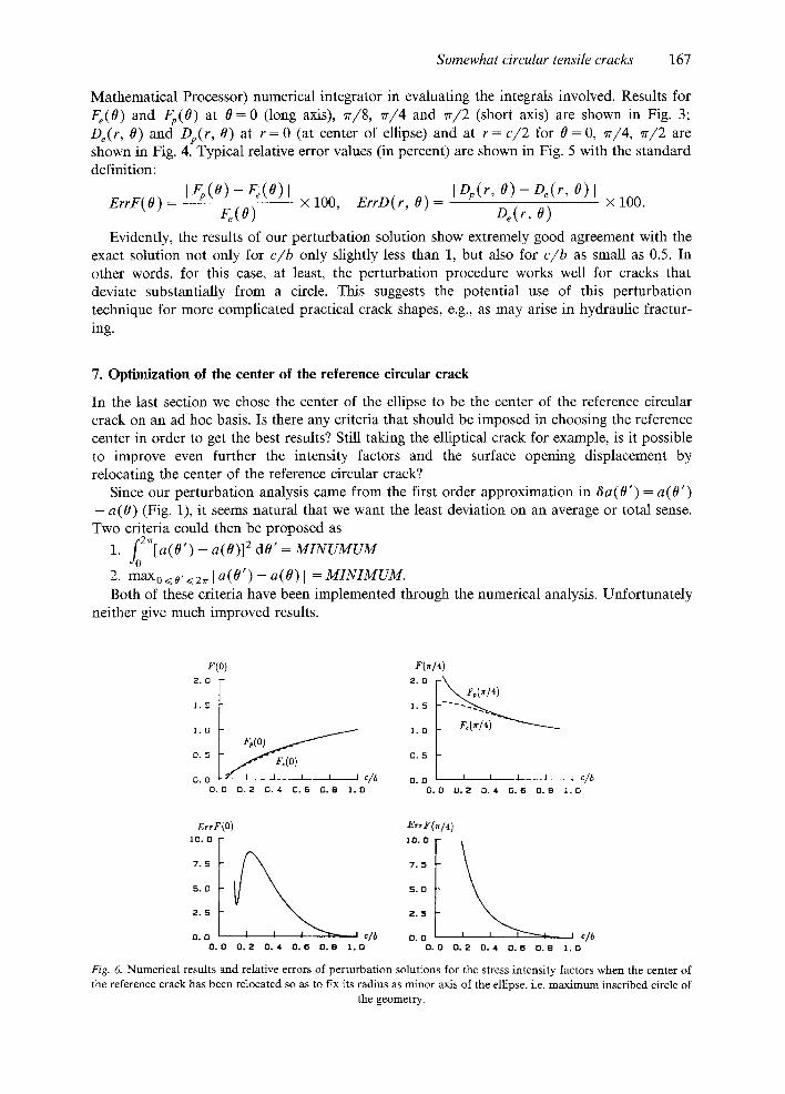
Mathematical Processor) numerical integrator in evaluating the integrals involved. Results for Fe(O ) and Fp(0) at 0 = 0 (long axis), ~r/8, ~r/4 and ~r/2 (short axis) are shown in Fig. 3; De(r, O) and Dp(r, O) at r = 0 (at center o f ellipse) and at r = c/2 for 0 = 0, 7r/4, ~r/2 are shown in Fig. 4. Typical relative error values (in percent) are shown in Fig. 5 with the standard definition:
Evidently, the results of our perturbation solution show extremely good agreement with the exact solution not only for c/b only slightly less than 1, but also for c/b as small as 0.5. In other words, for this case, at least, the perturbation procedure works well for cracks that deviate substantially from a circle. This suggests the potential use of this perturbation technique for more complicated practical crack shapes, e.g., as may arise in hydraulic fractur- ing.
7. Optimization of the center of the reference circular crack
In the last section we chose the center of the ellipse to be the center of the reference circular crack on an ad hoc basis. Is there any criteria that should be imposed in choosing the reference center in order to get the best results? Still taking the elliptical crack for example, is it possible to improve even further the intensity factors and the surface opening displacement by relocating the center of the reference circular crack?
Since our perturbation analysis came from the first order approximation in 8a(0')= a(O') - a (0) (Fig. 1), it seems natural that we want the least deviation on an average or total sense. Two criteria could then be proposed as
1 . . £2Vr[a (O ' ) -- a ( 0 ) ] 2 dO' = MINUMUM "13
2. m a X o < 0 , < 2 ~ [ a ( 0 ' ) -- a (O) I = M I N I M U M . Both of these criteria have been implemented through the numerical analysis. Unfortunately
neither give much improved results.
E(o)
1. D /
0 . 5
oo l / < y 0 / , , ,cj O . O 0 . 2 0 . 4 0 . @ 0 . 8 1 . 0
F(,14 2 . 0 - ~ )
1. O F,(w/4)
D. 5
0 . 0 O.
i i. l l i c /b 0.2 o.* o.s o.s 1.o
Er,F(O) 1 0 . 0
7 . 5
5 . 0
2 . 5
o. o ' c/6 0 . 0 0 . 2 0 . 4 0.@ 0. B 1 . 0
ErrFOr/4 ) lO.O
7 . 5
5 . 0
2 . 5
0 . 0 O.
J c/b 0 . 2 0 . 4 0 . 6 0 . 8 I , D
Fig. 6. Numerical results and relative errors of perturbation solutions for the stress intensity factors when the center of the reference crack has been relocated so as to fix its radius as minor axis of the ellipse, i.e. maximum inscribed circle of
the geometry.
168 H. Gao and J.R. Rice
By looking at Fig. 3, the reader could find that the perturbation results for K are the worst at the crack tip along the longer semi-axis. Therefore a specific study of the perturbation prediction of the stress intensity factor at this point was made in such a manner that we shift the center of the reference crack along the long semi-axis gradually towards the tip. We find at each c/b there corresponds an optimum value e for the shifted distance which closely matches the perturbation results to the exact results. This quantity satisfies e + c -- b. This suggests the criterion, not yet fully understood theoretically, to choose the maximum inscribed circle to be our reference circular crack, i.e., to choose a circle of radius c for the elliptical crack with b > c. The numerical results under this criterion for Fp and F e at 0 = 0 and ~r/4 (at 0 = ~r/2 they coincide with the unshifted case) are shown in Fig. 6. It shows a remarkable improvement over the previous results. It is left to future work to provide a theoretical background for this optimization criteria and for a better understanding of the perturbation method.
8. Conclusion
We have derived the full solution for the distribution of crack front stress intensity factor and crack face opening displacement along a somewhat circular planar tensile crack. The solution is exact to the first order in the deviation of the crack front from a circular shape.
The solution is based on knowledge of only the intensity factor distribution for a pair of unit wedge opening point forces on the crack face, as utilized in a method developed by Rice [1] for dealing with perturbed crack shapes. That method has its roots in a three dimensional extension [13] of Bueckner's [14] weight function theory for two dimensional elastic fields. The three dimensional extension by Rice related the weight function, of which the intensity factor distribution due to point force crack face loading is a special case, to elastic field variations in incremental non-uniform crack growth. It is that relation which is exploited [1] in using the weight function to solve for the elastic field due to perturbation of crack shape. Bueckner [15] presented and developed [16] an independent three dimensional extension of his weight function theory based on fundamental elastic fields having singularities stronger than those allowed for normal elastic fields of bounded energy (in any finite region about a crack tip). The equivalence of the two approaches is discussed by Bueckner [16,17] and Rice [1,6].
The solution which we derive here for somewhat circular cracks allows analysis of the configurational stability of circular cracks under axially symmetric loading. Loadings which are concentrated towards the center give stability. Those which increase with distance from the center give configurational instability for a longer wavelength mode or modes; the unstable modes extend to shorter wavelengths the more steeply the loading increases from the crack center.
Comparison of our perturbation solution to the exact solution for an elliptical crack suggests that accuracy is retained up to appreciable deviations from a circular shape. For example, the perturbation solution is good for the elliptical crack under remotely uniform tension even when the ratio of major to minor semi-axis length is as large as 2, and as large as 3 with the special choice of reference shape discussed in the last section. -This suggests that our perturbation solution will provide an acceptable solution for a very wide range of crack problems encoun- tered in practice, e.g., in hydraulic fracturing. Also, the solution can be used as a basis for examining simple models of such phenomena as internal crack growth in a medium of spatially variable fracture resistance.
Added note
Since completion of the original manuscript we learned of earlier work by Panasyuk [18] on the slightly non-circular tensile crack. We summarize his formulation and compare it to the present work in Appendix B.
Somewhat circular tensile cracks 169
Acknowledgement
T h e w o r k r e p o r t e d w a s s u p p o r t e d b y the O N R M e c h a n i c s D i v i s i o n , c o n t r a c t
N 0 0 0 1 4 - 8 5 - K - 0 4 0 5 wi th H a r v a r d Un ive r s i t y . W e a re g ra te fu l to V.I . F a b r i k a n t for s h o w i n g
h o w to s impl i fy s o m e in tegra l s in A p p e n d i x A a n d p o i n t i n g o u t the ear l ie r w o r k o n the p r o b l e m
b y Panasyuk .
References
1. J.R. Rice, Journal of Applied Mechanics 52 (1985) 571-579. 2. L.A. Galin, Contact Problems in the Theory of Elasticity (in Russian), Translation by H. Moss, North Carolina State
College Publications (1961). 3. H. Tada, P.C. Paris and G.R. Irwin, The Stress Analysis of Cracks Handbook, Del Research Corporation,
Hellertown, PA (1973). 4. G.P. Cherepanov, Mechanics of Brittle Fracture, Appendix A, McGraw-Hill (1979) 827. 5. K.P. Meade and L.M. Keer, Journal of Elasticity 14 (1984) 79-92. 6. J.R. Rice, International Journal of Solids and Structures 21 (1985) 781-791. 7. H. Gao and J.R. Rice, Journal of Applied Mechanics 53 (1986) 774-778. 8. G.R. Irwin, Journal of Applied Mechanics 29 (1962) 651-661. 9. A.E. Green and I.N. Sneddon, Proceedings, 'Cambridge Philosophical Society 46 (1950) 159.
10. M.A. Sadowsky and E. Steinberg, Journal of Applied Mechanics 16 (1949) 149. 11. B. Budiansky and R.J. O'Cormell, International Journal of Solids and Structures 12 (1976) 81-97. 12. J.D. Eshelby, Proceedings, Royal Society London A241 (1957) 376. 13. J.R. Rice, International Journal of Solids and Structures 8 (1972) 751-758. 14. H.F. Bueckner, Zeitschrifi fuer angewandte Mathematik und Mechanik 50 (1970) 529-546. 15. H.F. Bueckner, in Mechanics of Fracture 1: Methods of Analysis and Solution of Crack Problems (G.C. Sih, ed.)
Noordhoff, Leyden (1972) 329-314. 16. H.F. Bueckner, in Fracture Mechanics and Technology (G.C. Sih and C.L. Chow, eds.) Vol. II, Sijthoff and
Noordhoff (1977) 1069-1107. 17. H.F. Bueckner, International Journal of Solids and Structures (1986) submitted. 18. V.V. Panasyuk, Dopovidi Academii Nauk Ukrainskoi RSR (in Ukranian) No. 2 (1962) 891-895. 19. T.S. Sankar and V.I. Fabrikant, Journal of Applied Mechanics 49 (1982) 43-46. 20. I.M. Ryzhik, Table of Integrals, Series and Products, Academic Press (1965) Translated from Russian (A. Jeffrey,
ed.).
Appendix A
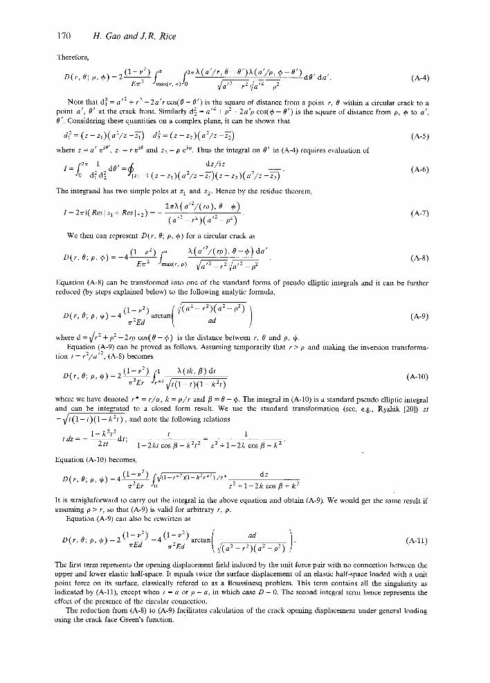
Crack face opening displacement for arbitrarily loaded, somewhat circular cracks
Equation (8) of the text gives the crack face opening displacement of a circular crack and (11), for which the quantities within it are given by (6) to (10), gives the opening displacement accurately to first order for a somewhat circular crack. Evidently, these equations are of the form,
where P(O, ep) is the crack face loading. D(r, O; p, e~) is obviously the Green's function on the crack face. Here we present some of the results of carrying out some integrals which define D(r, 0; 0, 0) of this expression exactly to first order in the deviation from a circular shape.
For conciseness of the formulae we introduce the following notation, following Sankar and Fabrikant [19]:
h (k , 4~) = (1 - k 2 ) / ( 1 - 2 k cos ~/, + k2). (1-2)
For a circular crack, by switching the order of integration on a' and p, (8) becomes,
Au(r, O) =Au°[r, O; a]
= 2 ( 1 - - p 2 ) [2~rfaf [a f2~rh(a'/,,O~_O') X(a ' /p ,~_-O') dO, da ,}p(p ,q~)pdpd~" (1-3) Ecr 3 JO JO ~Jmax(r,o)JO ~ : 7 ~ : ~
1 7 0 H. Gao and J .R. R ice
Therefore,
D ( r , O ; p , e p ) = Z ( 1 - v 2 ) [a f 2 ,~ ) t (a ' / r ,O-O ' ) )~ (a ' / p , ep-O' )dO, da,. (A-4) Eo3 o
Note that d 2 = a ' 2 _{_ r 2 _ 2 a ' r cos(0 - 0 ' ) is the square of distance from a point r, 0 within a circular crack to a point a ' , 0 ' at the crack front. Similarly d 2 = a '2 +p2 -2a 'p c o s ( 0 - 0 ' ) is the square of distance from p, ~ to a ' , 0 ' . Considering these quantities on a complex plane, it can be shown that
d 2 = (z - Zl)(aZ/z -Ta) d 2 = (z - z2)(a2/z -z22 ) (A-5)
where z = a ' e i°', z 1 = r e i° and z 2 = p e i'~. Thus the integral on 0 ' in (A-4) requires evaluation of
,2,, 1 , -- dz / i z I=J¢ ~ d 0 =~ , - (A-6)
0 d i d 2 Izl=l(z-zl)(a2/z-~i)(z-z2)(a2/z-~2) The integrand has two simple poles at z 1 and z 2. Hence by the residue theorem,
I=2~ri (Res lz l+Reslz2 ) 2~rX(a'Z/(ro), 0 - ~ ) (1 -7) ( a '2 _ r 2 ) ( a '2 - O 2)
We then can represent D(r, 0; O, ~) for a circular crack as
D ( r , O ; p , O ) = _ 4 ( 1 - u 2 ) [a X ( a ' 2 / ( r o ) , O - ~ ) d a ' (A-8) E~ "2 Jmax(r,o) ~ a ~ _ p 2
Equation (A-8) can be transformed into one of the standard forms of pseudo elliptic integrals and it can be further reduced (by steps explained below) to the following analytic formula,
( 1 " u2) { -- r 2 ) ( a 2 -- 10 2) ] D(r, 0; p, ~ ) = 4 ~ a r c t a n [ ~(a2 (1 -9) ad ]
where d =v / r 2 + O 2 -2tO cos(0 - ~5) is the distance between r, 0 and O, ~. Equation (A-9) can be proved as follows. Assuming temporarily that r > p and making the inversion transforma-
tion t = r2/a '2, (A-8) becomes
2(1- - l , '2 ) f l ~(tk , l~)dt D(r , O; O, ep) = ~r2ETdr*2 V/ t (1 - t ) ( 1 - k2t) (A-10)
where we have denoted r* = r/a, k = p / r and/3 = 0 - ~. The integral in (A-10) is a standard pseudo elliptic integral and can be integrated to a closed form result. We use the s tandard transformation (see, e.g., Ryzhik [20]) zt = v / t ( 1 - t ) (1 - k2t) , and note the following relations
1 - k2t 2 t 1 t dz dt;
2zt 1 - 2 k t c o s f l + k2t 2 - z 2 + 1 - 2 k cos/3 + k 2 "
Equation (A-10) becomes,
D(r, 0; O, qb) = 4 ( 1 - ~'2) f~/(1-r*2)(1-kar*2)/r* dz ~r2Er Jo z2 + l - 2k cos /3 + k 2
It is straightforward to carry out the integral in the above equation and obtain (A-9). We would get the same result if assuming 0 > r, so that (A-9) is valid for arbitrary r, P.
The first term represents the opening displacement field induced by the unit force pair with no connection between the upper and lower elastic half-space. It equals twice the surface displacement of an elastic half-space loaded with a unit point force on its surface, classically refered to as a Boussinesq problem. This term contains all the singularity as indicated by (A-11), except when r = a or p = a, in which case D = 0. The second integral term hence represents the effect of the presence of the circular connection.
The reduction from (A-8) to (A-9) facilitates calculation of the crack opening displacement under general loading using the crack face Green's function.
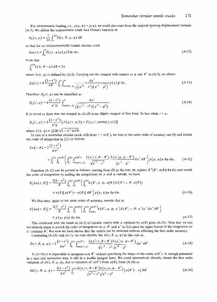
Somewhat circular tensile cracks 171
For axisymmetric loading, i.e., p (p, ~) = p (p), we could also start from the original opening displacement formula (A-3). We define the axisymmetric crack face Green's function as
1 r 2 ~ .
Da(r,o)=~TJo D(r,O;p,~)dO
so that for an axisymmetrically loaded circular crack
Au( r ) = ~D~( r, p ) p( o )2~ro do. (1-12)
Note that
f02~X(k, O - ~ ) dO = 2~r
where X(k, if) is defined by (A-2). Carrying out the integral with respect to ~ and O' in (A-3), we obtain
Au(r) = 8 ( 1 - va) (a[a da' .p(p)p do. (1-13) ~E Jo Jmax(r, O) ~ ( a '2 _ r 2 ) ( a '2 -- p2)
Therefore Da(r, p) can be identified as
Da(r , p) = 4 ( 1 - v 2) [a da' (1-14) ~2E Jmax(r, o) ~ ( a '2 _ r 2 ) ( a '2 _ p2)
It is trivial to show that the integral in (A-14) is ,an elliptic integral of first kind. In fact when r > O,
where F(k, ~) = fo*dO/~l - k 2 sin20 - In case of a somewhat circular crack with front r = a(O'), we may to the same order of accuracy use (6) and switch
Equation (A-15) can be proved as follows: starting from (9) in the text, we replace K ° [ 0 ' ; a(0)] by (6) and switch the order of integration by pulling the integrations on 0 and ~ outside, we have
8[2xu(r , 0)1 = 2 ( 1 E V2 ) ( , ,o ~o t~o k o ; p,*; a(O))k(O'; r,O; a(O))
x a(O)[a(O')- a ( 0 ) ] dO'}p(p, ~b)O do d~b. (1-16)
We thus may, again to the same order of accuracy, rewrite this as
8 [ A u ( r , O)l 2 ( 1 - v 2 ) (2=[o(o>((~f~(o'>k( o, a')a' da' dO'} E Jo ~o k~o ~a(O) ; O,~;a')k(O'; r,O;
×P(P, ~)O do dq~. (A-17)
This combined with the result in (A-3) of circular cracks with a replaced by a(O) gives (A-15). Note that we can not directly argue to switch the order of integration on P, O' and a' in (11) since the upper bound of the integration on a ' contains 0'. But now we have shown that the orders can be switched without affecting the first order accuracy•
Comparing (A-15) with (A-1), we may identify the D(r, 0; 0, ~) in this case as
D(r, 0; O, * ) = 2 ( 1 - v 2 ~ ) [2~r[a(O') X(a'/r, O-O')X(a'/o, ~ - O ' ) d a, dO'. (1-18)
In (A-18) it it impossible to integrate over 0 ' without specifying the shape of the crack a(O'). It, though presented in a nice and symmetric way, is still in a double integral form. We could alternatively directly obtain the first order variation of D(r, 0; 0, ~), due to variation of a(O') from a(O), from (A-16) as
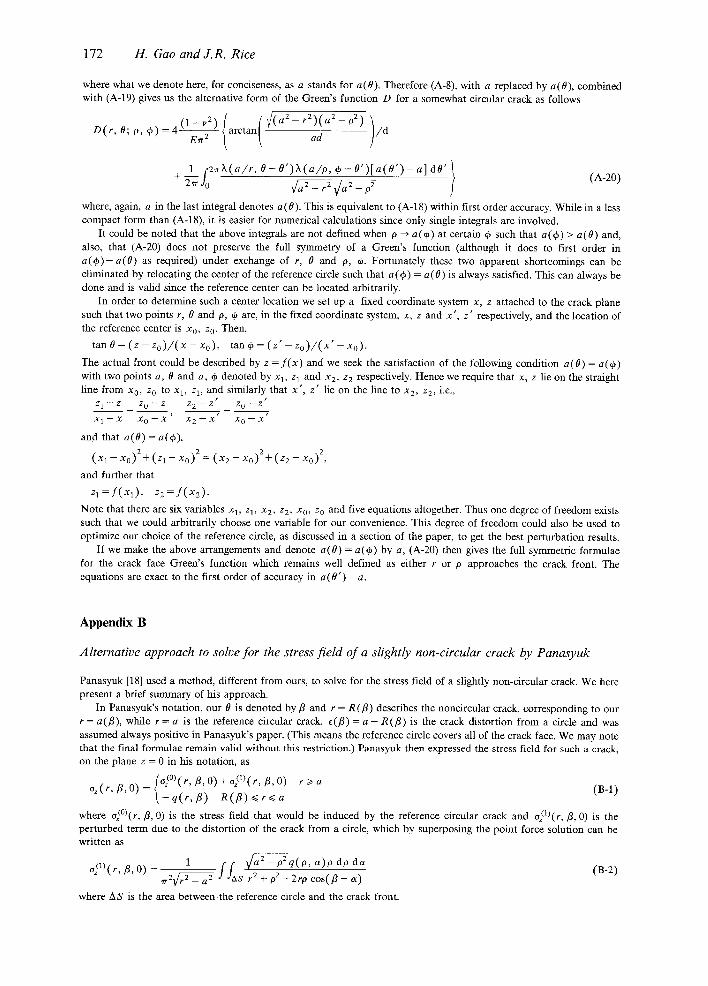
where what we denote here, for conciseness, as a stands for a(O). Therefore (A-8), with a replaced by a(O), combined with (A-19) gives us the alternative form of the Green's function D for a somewhat circular crack as follows
~ { (~(a2-r2)(a2-02) ) D ( r, 0 ; p, q~ ) = 4 arctan ad / d
where, again, a in the last integral denotes a(O). This is equivalent to (A-18) within first order accuracy. While in a less compact form than (A-18), it is easier for numerical calculations since only single integrals are involved.
It could be noted that the above integrals are not defined when p ---, a ( ~ ) at certain ~ such that a(4~) > a(O) and, also, that (A-20) does not preserve the full symmetry of a Green's function (although it does to first order in a(eo)-a(O) as required) under exchange of r, 0 and p, ~. Fortunately these two apparent shortcomings can be eliminated by relocating the center of the reference circle such that a (if) = a (0) is always satisfied. This can always be done and is valid since the reference center can be located arbitrarily.
In order to determine such a center location we set up a fixed coordinate system x, z attached to the crack plane such that two points r, 0 and p, ff are, in the fixed coordinate system, x, z and x ' , z ' respectively, and the location of the reference center is x0, z o. Then,
tan 0 = (z - Zo) / (x - Xo) , tan qa = (z ' - Zo) / (x ' - xo).
The actual front could be described by z = f ( x ) and we seek the satisfaction of the following condition a(O) = a(~) with two points a, 0 and a, q, denoted by xl, z 1 and x2, z 2 respectively. Hence we require that x, z lie on the straight line from x0, z 0 to xl , z> and similarly that x ' , z ' lie on the line to x2, Z2, i.e.,
Z 1 - - Z Z 0 - - Z Z 2 - - Z t Z 0 - - Z p
X 1 - - X X 0 - - X ' X 2 - - X t X 0 - - X *
and that a( O) = a( e~),
( X 1 - - X 0 ) 2 q- ( Z 1 - - X 0 ) 2 = ( X 2 - - X 0 ) 2 - { - ( Z 2 - - X 0 ) 2 ,
and further that
z , = f ( x l ) , z 2 = f ( x 2 ) .
Note that there are six variables Xl, zl, x2, z2, Xo, z 0 and five equations altogether. Thus one degree of freedom exists such that we could arbitrarily choose one variable for our convenience. This degree of freedom could also be used to optimize our choice of the reference circle, as discussed in a section of the paper, to get the best perturbation results.
If we make the above arrangements and denote a(O) = a ( ~ ) by a, (A-20) then gives the full symmetric formulae for the crack face Green's function which remains well defined as either r or P approaches the crack front. The equations are exact to the first order of accuracy in a(O' ) - a.
Appendix B
Alternative approach to solve for the stress hem of a slightly non-circular crack by Panasyuk
Panasyuk [18] used a method, different from ours, to solve for the stress field of a slightly non-circular crack. We here present a brief summary of his approach.
In Panasyuk's notation, our 0 is denoted by fl and r = R(fl) describes the noncircular crack, corresponding to our r = a(fl), while r = a is the reference circular crack. ~(/3) = a - R(fl) is the crack distortion from a circle and was assumed always positive in Panasyuk's paper. (This means the reference circle covers all of the crack face. We may note that the final formulae remain valid without this restriction.) Panasyuk then expressed the stress field for such a crack, on the plane z = 0 in his notation, as
f%(°)(r, B, o)+ @l)(r, r , o) r > a o~(r, B, O) (B-l )
~ - q ( r , fl) R ( f l ) < ~ r ~ a
where o~°)(r,/3, O) is the stress field that would be induced by the reference circular crack and o)l)(r,/3, O) is the perturbed term due to the distortion of the crack from a circle, which by superposing the point force solution can be written as
1 ~ - p 2 q ( p , a)o do da o/1)(r,
~ r 2 ~ f f~s r2 +o2-2rocos(/3-a) /3, O) (B-2)
where AS is the area between4he reference circle and the crack front.
Somewhat circular tensile cracks 173
Panasyuk further introduced the following representation,
of°)(r, fi, O)=q~(r, f l ) / ~ q(r, f l)=do(r, f l ) / I r 2 - R2(fi ) (B-3)
where ~(r , fl) and do(r, fl) contain no singularities. The fact that there is no singularity at r = a states
li ( . . . . . 1 f f ~ - p 2 q ( p , a ) p d o d a } (B-4) m {~[r , t J ) t ~ JJAs ' 2 , 2 r+a[ rr r + P - 2 r p c o s ( f l - a ) /
Combining (B-3) and (B-4), Panasyuk was able to establish the following integral equation
__l mr (r°/a202 0(0o,0d0 } q,(a, /3) da. (B-5) ,:7,2 r~ a~'O [aR(a)gp~R2~-(o~) r 2 -}- p 2 --2ro cos(fl -- a )
To solve this to the first order of accuracy, Panasyuk adopted a linear expansion of the regular functions +(r , /3) and do(r,/3) so that
do(r, fl ) = do(a, fl ) + ( r - a ) dor ( a , fi ) * ( r , fl) = ~(a , f l ) + ( r - a)~r(a , fi). (B-6)
Given (B-6), (B-5) can be solved to the first order of e(fl). The result is
1 c2~ d c o t f i @ ~ d a " 4 ( a , f l ) =-do(a,fl)+12E(fl)dor(a,fl)+~TavaPVJo ~ - d [ e ( a ) d o ( a , - ) 1 (B-7)
As implied by (B-7), - do(a, fl) differs from +(a , fl) by a small quantity of first order; so does - dot(a,/3) from %(a , /3 ) . Therefore it would make a second order difference when one changes the do's in the last two terms in (B-7) to ~b's. Hence we have now
1 2~ d a)] c o t ~ @ ~ d a . - do(a, /3) = ~ ( a , / 3 ) + ½E(/3)~br(a, /3)+ ~ a P V f o ~ a [{ (a )~b(a , - - (B-8)
This enabled Panasyuk also to get a first order representation of the stress field of a slightly non-circular crack
o,(r,/3,0) 1 (~ (a , /3 )+½e( /3 )~r (a , /3 )+ /ra-
1 2~ d c o t ~ d a . +(r-a)hbr(a,/3)+-4~a,17.aPgfo ~ [ c ( a ) ~ b ( a , a)] (B-9)
It is easy in the first place to see the correspondence of Panasyuk's formula and (15) in the text. If we want to express Panasyuk's formula in our notations, we first introduce the following expressions
oO(r,O,O ) ~/7 { K ° [ a ; O ] + ( r - a ) K ° [ a ; O ] } %(r ,O,O)= X(O)¢a(O) (B-10) ¢~r(r 2 - a 2) ~vr[r 2 - - a 2 ( 0 ) ]
for the stress field of a circular crack of radius a and slightly non-circular crack described by r = a(O), valid in the vicinity of the crack edge as in (B-6).
Thus (B-9) becomes, with reference circular crack radius a (a g= a(O) in general), in our notation as used in the text
, 1 ,,.~c2~K°[a • O ' ] [a -a (O ' ) ] K(O)=K°[a; O]-½[a-a(O)lK°D; 0 l -~ - - . . . . - ' - - ~ , ~ m ~ , ~ , dO'. (B-11) 8~r J0 a s i n2 [ (0 - -0 ) / 2 ]
It is worth noticing that if we choose a reference circular crack such that a = a(O) is always satisfied, i.e. relocate the reference circle in such a way (B-11) becomes exactly the same as (15) in the text.
One may also verify from formulae here and in the body of the paper that t~r(a, 18) or K°[a; 0] can be derived solely from ~p(a,/3) or K° [a ; 0] by the following formula under general loading
K r [ a ; O]=23K°[a; 0] 1_ [2~ K ° [ a ; 0 ' ] d 0 ' (B-12) 3a + 4~rPVjo as in2[(O-O') /2]"
This is expected to be true if (B-11), based on Panasyuk's results, is a correct first order formula. Substituting (B-12) into (B-11), we have
K ( O ) = { K ° [ a ; O]+[a(O) -a] 3K°[a; O] \+ 8~1 p v r Z £ K ° [ a ; O ' l [a (O) -a (O ' ) ] dO'. (B-13) 3a j .t o a sin~ [ ~ _-- 0 5 / ~
which can be directly obtained from our (15) to first order accuracy by simply expanding linearly over a - a(O) (we can call the reference circle of radius a (0) the 'relocated circle'). Equation (B-13) has the advantage that the reference circle is fixed in size.
174 H. Gao and J.R. Rice
Summing up, Panasyuk used a method of solving to the first order an integral equation for the stress field of a sfightly non-circular crack. His approach is quite different from ours and led to the same results within first order accuracy. This coincidence shows that his procedure of locating the reference circular crack front wholly outside the actual crack is unnecessary for validity of the final results. However, it is not yet clear as to how the actual steps of his derivation, described in connection with (B-l) to (B-5), could be changed to allow for a choice of a reference crack not meeting that condition. Nevertheless, the expected analyticity of his resulting formulae in c could have been used to suggest that they would remain valid for other than the positive e which he assumed.
R~smn~
On applique la m6thode propos6e par Rice (1985) pour la solution du champ 61astique d'une fissure dont le front S'6carte d'une forme de r6f6rence, h la solution des probl~mes d'61asticit6 relatifs h des fissure planaires sensiblement circulaires et soumises h tension sous l'effet de distribution de charges arbitraires. La m6thode est bas6e sur la connaissance du facteur d'intensit6 de contraintes le long d'une fissure circulaire, soumise ~t un couple de forces d'ouverture par coin qui agissent sur sa surface. Pour ce facteur d'intensit6 de contrainte et des distributions donn6es du d6placement d'ouverture de la fissure, on d6duit une solution compl+te, exacte au premier ordre, d6crivant la d6viation par rapport h la forme circulaire. Les r6sultats obtenus pour une perturbation suivant une onde harmonique sugg6rent qu'nne fissure circulaire soumise h sollicitation axi-sym6trique, peut pr6senter une configuration instable, c'est-~-dire cro~te selon une forme autre que circulaire, en pr6sence de solficitations croissant en intensit6 au fur et mesure que 1'on s'61oigne du centre. La m~me forme de variation en fonction de la longueur d'arc le long du bord de la fissure est constat6e pour des fissures circulaires soumis h des perturbations de forme harmonique, en ce qui regarde le facteur d'intensit6 de contraintes; ceci avait 6t6 trouv6 dans un travail pr6c6dent pour des fissures h6miplanaires. Pour tester la solution des perturbations, on consid~re qu'une fissure elliptique plane sous tension est une 6volution perturb6e d'une fissure circulaire. On compare les r6sultats d6riv6s des formules de perturbations et mis sous forme num6rique aux solutions exactes disponibles dans la litt6rature. On trouve que l'accord est excellent, m~me dans le cas off les longueurs des demi-axes de l'eUipse sont dans un rapport de deux (voire trois) pour des conditions sp6ciales de position de la fissure circulaire de r6f~rence. Ceci sugg+re que la m6thode des perturbations pr6sent6es, si elle n'est th6oriquement exacte que pour le premier ordre, peut ~t l'usage produire des r6sultats acceptables dans le cas de fissures planaires dont la forme d6vie de mani6re appreciable d'une forme circulaire.