SERVICE MANUAL LCD Digital Color TV AZ1-H Chassis 9-888-354-01 Version Date Subject 1.0 8/13/2010 No revisions or updates are applicable at this time. ORIGINAL MANUAL ISSUE DATE: 8/2010 HISTORY INFORMATION FOR THE FOLLOWING MANUAL:
Transcript
SERVICE MANUAL
LCD Digital Color TV
AZ1-H Chassis
9-888-354-01
Version Date Subject1.0 8/13/2010 No revisions or updates are applicable at this time.
ORIGINAL MANUAL ISSUE DATE: 8/2010
HISTORYINFORMATIONFORTHEFOLLOWINGMANUAL:
SERVICE MANUAL
LCD Digital Color TV
AZ1-H Chassis
9-888-354-01
Self DiagnosisSupported model
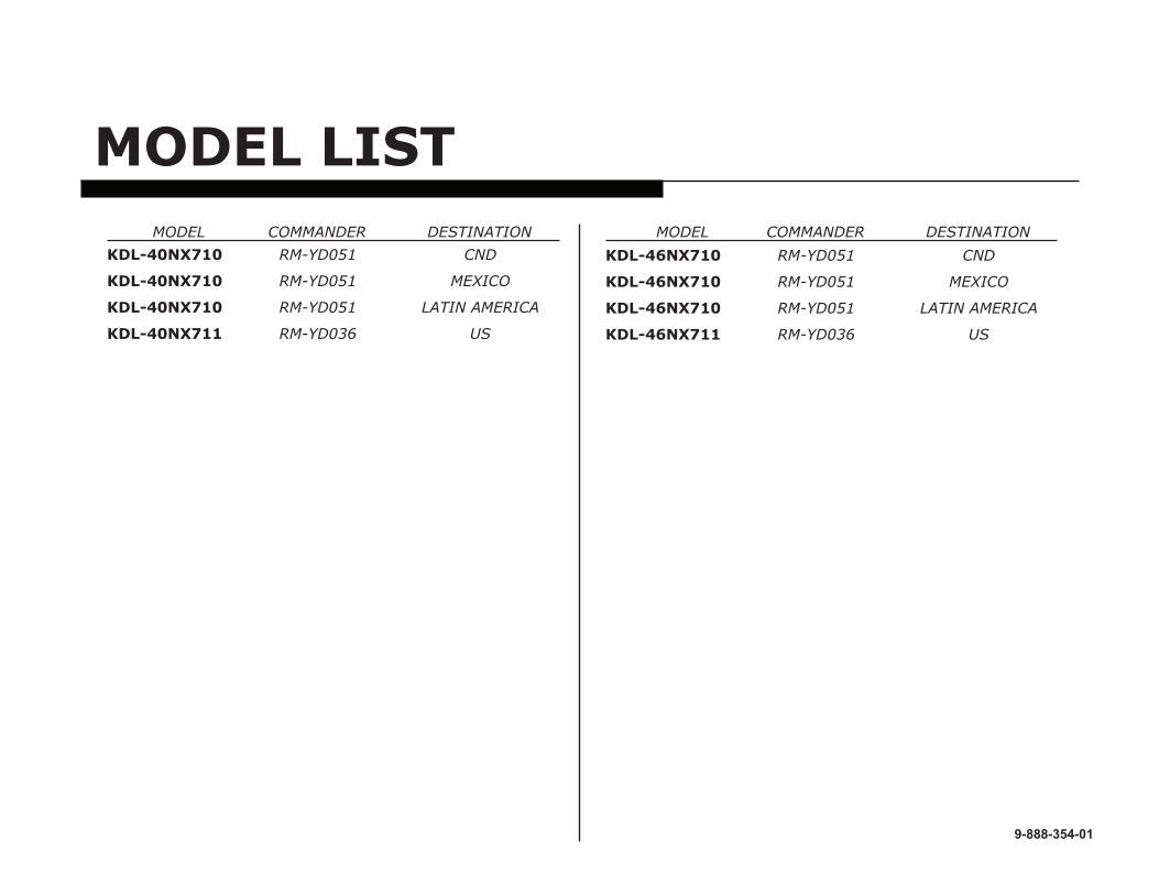
MODEL LIST MODEL COMMANDER DESTINATION MODEL COMMANDER DESTINATION
Warnings and Cautions ..................................................................................................................................................................3
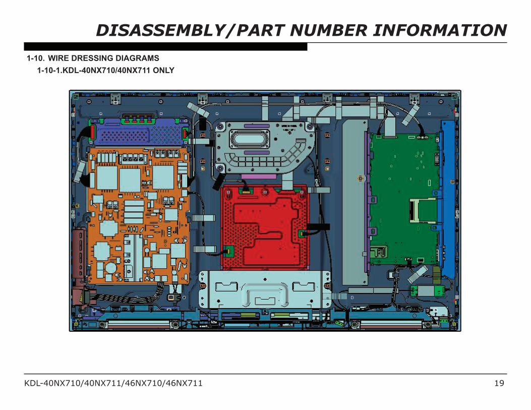
SEC 1. Disassembly/Part Number Information ..........................................................................................................................141-1. Table-Top Stand Assembly Removal .............................................................................................................................141-2. Rear Cover, Bezel Bottom, Speakers and Switch Unit Removal...................................................................................151-3. G9A/G9B (Power) Boards, BUHT Board, HLT Board and Wireless LAN Card Removal ..............................................161-4. Cleaning the LCD Panel Assembly ...............................................................................................................................171-5. Screw Legend................................................................................................................................................................171-6. Connectors ....................................................................................................................................................................171-7. Accessories and Packing ..............................................................................................................................................181-8. Miscellaneous ................................................................................................................................................................181-9. Remote Commander .....................................................................................................................................................181-10. Wire Dressing Diagrams ................................................................................................................................................19
1-10-1. KDL-40NX710/40NX711 Only .................................................................................................................................................... 191-10-2. KDL-46NX710/46NX711 Only .................................................................................................................................................... 20
SEC 2. Service Adjustments ........................................................................................................................................................212-1. Accessing Service Adjustment Mode ............................................................................................................................21
2-1-1. Viewing the Service Menus ........................................................................................................................................................ 222-1-2. Using the Remote Commander to View or Change Service Data ............................................................................................. 23
KDL-40NX710/40NX711/46NX710/46NX711 ii
TABLE OF CONTENTS
2-2. Adjustments After Replacing the BUHT Board or LCD Panel Assembly .......................................................................232-2-1. Updating the Software ............................................................................................................................................................... 232-2-2. Selecting the Model ................................................................................................................................................................... 242-2-3. Selecting the Destination ........................................................................................................................................................... 252-2-4. Resetting the Data Value in the Panel Engine Micro ................................................................................................................. 262-2-5. Verifying the Emitter Output Level ............................................................................................................................................. 292-2-6. Verifying the Model and Panel Information ................................................................................................................................ 302-2-7. Reconnecting All Cables ............................................................................................................................................................ 30
2-3. White Balance Adjustments ...........................................................................................................................................312-4. Resetting the TV to Factory Condition ...........................................................................................................................32
2-4-1. Resetting the TV to Factory Condition Using Service Mode ...................................................................................................... 32
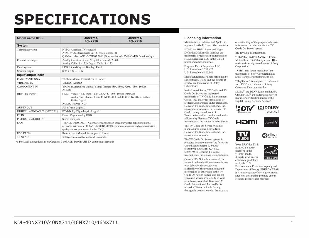
Licensing InformationMacintosh is a trademark of Apple Inc., registered in the U.S. and other countries.
HDMI, the HDMI Logo, and High-Definition Multimedia Interface are trademarks or registered trademarks of HDMI Licensing LLC in the United States and other countries.
Manufactured under license from Dolby Laboratories. Dolby and the double-D symbol are trademarks of Dolby Laboratories.
In the United States, TV Guide and TV Guide On Screen are registered trademarks of TV Guide Entertainment Group, Inc. and/or its subsidiaries or affiliates, and are used under a license by Gemstar-TV Guide International, Inc. and/or its subsidiaries. In Canada, TV Guide is a registered mark of Transcontinental Inc., and is used under a license by Gemstar-TV Guide International, Inc. and/or its subsidiaries.
The TV Guide On Screen system is manufactured under license from Gemstar-TV Guide International, Inc. and/or its subsidiaries.
The TV Guide On Screen system is protected by one or more of the following United States patents 6,498,895; 6,850,693; 6,396,546; 5,940,073; 6,239,794 to Gemstar-TV Guide International, Inc. and/or its subsidiaries.
Gemstar-TV Guide International, Inc. and/or its related affiliates are not in any way liable for the accuracy or availability of the program schedule information or other data in the TV Guide On Screen system and cannot guarantee service availability in your area. In no event shall Gemstar-TV Guide International, Inc. and/or its related affiliates be liable for any damages in connection with the accuracy
or availability of the program schedule information or other data in the TV Guide On Screen system.
Blu-ray Disc is a trademark.
“BRAVIA” and , S-Force, Motionflow, BRAVIA Sync, and are trademarks or registered marks of Sony Corporation.
“XMB” and “xross media bar” are trademarks of Sony Corporation and Sony Computer Entertainment Inc.
“PlayStation” is a registered trademark and “PS3” is a trademark of Sony Computer Entertainment Inc.
DLNA®, the DLNA Logo and DLNA CERTIFIED® are trademarks, service marks, or certification marks of the Digital Living Network Alliance.
Your BRAVIA TV is ENERGY STAR® qualified in the “Home” mode. It meets strict energy efficiency guidelines set by the U.S. Environmental Protection Agency and Department of Energy. ENERGY STAR is a joint program of these government agencies, designed to promote energy efficient products and practices.
KDL-40NX710/40NX711/46NX710/46NX711 2
SPECIFICATIONS
*2 Download Acquisition Mode (DAM) is used for software updates and/or collecting data for TV Guide On Screen.• Optional accessories availability depends on its stock.• Design and specifications are subject to change without notice.
Model name KDL- 46NX711/46NX710
40NX711/40NX710
Power and othersPower requirement 110-240 V AC, 50/60 Hz (U.S.A./Canada 120 V AC, 60 Hz)
Power consumption153 W 137 W
in use
in DAM*2 W 22
(You may hear a clicking noise during the download but this is normal.)
in standby Less than 0.12 W with 120 V AC and less than 0.2 W with 240 V AC
Screen size(inches measured diagonally)
46 inches 40 inches
roh( stod 029,1 noituloser yalpsiD izontal) × 1,080 lines (vertical)
Speaker Full range (mm)
(inches)Woofer (mm)
(inches)
20 × 70 (4)13/16 × 2 7/8 (4)
Φ 60 (1)Φ 2 3/8 (1)
20 × 90 (2)13/16 × 3 5/8 (2)
40 × 90 (1)1 5/8 × 3 5/8 (1)
Dimensions with stand (mm)(inches)
944 × 612 × 24537 1/4 × 24 × 9 3/4
without stand (mm)(inches)
944 × 582 × 3237 1/4 × 23 × 1 1/4
wall-mount hole pattern (mm) 003 × 003
wall-mount screw size (mm) M6 (length: 8-12 mm)
Mass with stand (kg)/(lb.) 24.4/53.8without stand (kg)/(lb.) 20.5/45.2
Supplied accessories See “Checking the accessories”.
Optional accessories Connecting cables / Support Belt Kit / Wall-Mount Bracket / Wall-Hanging Bracket / 3D Glasses / 3D Sync Transmitter
1,083 × 690 × 27042 3/4 × 27 1/4 × 10 3/4
1,083 × 660 × 3142 3/4 × 26 × 1 1/4
19.8/43.7
16.1/35.5
Checking the accessoriesTable-Top Stand (1)*1
Remote control (1)*2
Size AAA batteries (2)Hexagon wrench (1)Assembling screws for Table-Top Stand (4)(KDL-46NX711 and KDL-46NX710 only)Assembling screws for Table-Top Stand (2)(KDL-40NX711, KDL-40NX710 only)3D Glasses (battery included) (2)(KDL-46/40NX711 only)Pouch for 3D Glasses (2)(KDL-46/40NX711 only)3D Sync Transmitter (1)(KDL-46/40NX711 only)Double-sided tape (2)(KDL-46/40NX711 only)
*1 KDL-46/40NX711 and KDL-46/40NX710models requires assembling. Refer to other leaflet to assemble the Table-Top Stand.
*2 Please refer to the model name printed on the remote control.
KDL-40NX710/40NX711/46NX710/46NX711 3
CautionThese servicing instructions are for use by qualified service personnel only. To reduce the risk of electric shock, do not perform any servicing other than that contained in the operating instructions unless you are qualified to do so.
Carrying tHE tV
WARNINGSANDCAUTIONS
• Carry the TV with the adequate number of people; larger size TVs require two or more people.• Correct hand placement while car rying the TV is very importa nt for safety and to avoid
damage.
Warning!!An isolation transformer should be used during any service to avoid possible shock hazard, because of live chassis. The chassis of this receiver is directly connected to the AC power line.
! SafEty-rElatEd ComponEnt Warning!!Components identified by shading and ! mark on the exploded views are critical for safe operation. Replace all components with Sony parts whose part numbers appear as shown in this manual or in supplements published by Sony. It is essential that all critical parts be replaced only with the part number specified in this manual to prevent electric shock, fire, or other hazard.Circuit adjustments that are critical for safe operation are identified in this manual. Follow these procedures whenever critical components are replaced or improper operation is suspected.
NOTE: Do not modify the original design without obtaining written permission from the manufacturer or you will void the original parts and labor guarantee.
KDL-40NX710/40NX711/46NX710/46NX711 4
attEntion!!Ces instructions de service sont à l’usage du personnel de service qualifié seulement. Pour prévenir le risque de choc électrique, ne pas faire l’entretien autre que celui contenu dans le Mode d’emploi à moins que vous soyez qualifié faire ainsi.
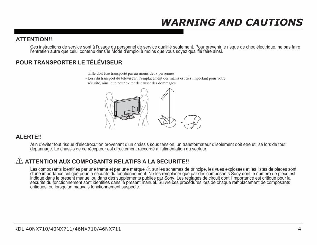
pour tranSportEr lE tÉlÉViSEur• T ransportez le téléviseur av ec le nombre de personnes approprié ; un téléviseur de grande
taille doit être transporté par au moins deux personnes. • L ors du transport du téléviseur , l’emplacement des mains est très important pour vo tre
sécurité, ainsi que pour év iter de causer des dommages.
alErtE!!Afin d’eviter tout risque d’electrocution provenant d’un chássis sous tension, un transformateur d’isolement doit etre utilisé lors de tout dépannage. Le chássis de ce récepteur est directement raccordé à l’alimentation du secteur.
! attEntion aux CompoSantS rElatifS a la SECuritE!!Les composants identifies par une trame et par une marque ! sur les schemas de principe, les vues explosees et les listes de pieces sont d’une importance critique pour la securite du fonctionnement. Ne les remplacer que par des composants Sony dont le numero de piece est indique dans le present manuel ou dans des supplements publies par Sony. Les reglages de circuit dont l’importance est critique pour la securite du fonctionnement sont identifies dans le present manuel. Suivre ces procedures lors de chaque remplacement de composants critiques, ou lorsqu’un mauvais fonctionnement suspecte.
WARNING AND CAUTIONS
KDL-40NX710/40NX711/46NX710/46NX711 5
Handling tHE glaSS aSSEmblyUse the following precautionary guidelines when replacing the Glass Assembly to avoid material degradation or screen coating degradation, and ensure that dust, dirt, or fingerprints are not left between the glass and the LCD panel.
R Replace the Glass Assembly in a brightly lit and clean room.
R Place the replacement Glass Assembly on a dark cloth to make it easier to see dust and dirt particles.
R Wear anti static gloves to avoid leaving finger prints on the glass.
R Use a dry, soft MicroFiber cloth, such as a lint free polishing cloth, to gently wipe the glass to remove any dust or dirt particles.
R If the glass needs additional cleaning, slightly moisten the cloth with a diluted mild soap or mild detergent solution, or use a compressed air duster (spray can type).
R After replacing the Glass Assembly, verify there are no dark spots or finger prints visible on the screen.
Caution
W Do Not use paper towels, any type of abrasive pad, rags, rubber or vinyl materials to clean the screen. Using these materials could easily scratch the screen which may result in permanent damage.
W Do Not se any cleaning product containing alkaline/acid cleaner, scouring powder, or volatile solvent, such as alcohol, ammonia, benzene, thinner or insecticide. Using any of these harsh cleaners may result in permanent damage to the screen.
W Do Not spray water or detergent directly onto the TV screen . If liquid drips into the bottom of the screen it may cause a failure.
WARNING AND CAUTIONS
KDL-40NX710/40NX711/46NX710/46NX711 6
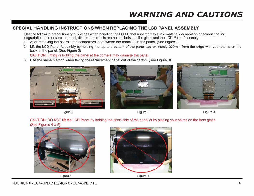
SpECial Handling inStruCtionS WHEn rEplaCing tHE lCd panEl aSSEmblyUse the following precautionary guidelines when handling the LCD Panel Assembly to avoid material degradation or screen coating degradation, and ensure that dust, dirt, or fingerprints are not left between the glass and the LCD Panel Assembly.1. After removing the boards and connectors, note where the frame is on the panel. (See Figure 1)2. Lift the LCD Panel Assembly by holding the top and bottom of the panel approximately 200mm from the edge with your palms on the
back of the panel. (See Figure 2) CAUTION: Lifting or holding the panel at the corners may damage the panel.3. Use the same method when taking the replacement panel out of the carton. (See Figure 3)
Figure 1 Figure 2 Figure 3
CAUTION: DO NOT lift the LCD Panel by holding the short side of the panel or by placing your palms on the front glass. (See Figures 4 & 5)
Figure 4 Figure 5
WARNING AND CAUTIONS
KDL-40NX710/40NX711/46NX710/46NX711 7
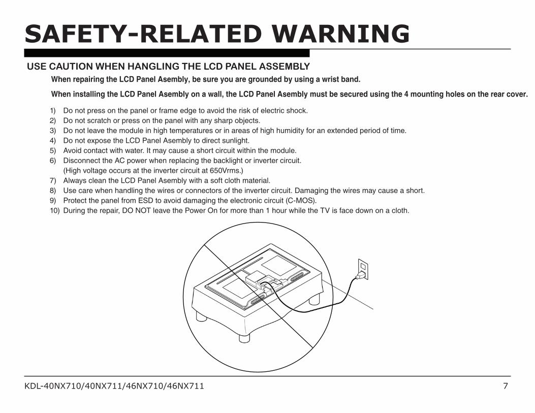
uSE Caution WHEn Hangling tHE lCd panEl aSSEmblyWhen repairing the LCD Panel Asembly, be sure you are grounded by using a wrist band.
When installing the LCD Panel Asembly on a wall, the LCD Panel Asembly must be secured using the 4 mounting holes on the rear cover.
1) Do not press on the panel or frame edge to avoid the risk of electric shock.2) Do not scratch or press on the panel with any sharp objects.3) Do not leave the module in high temperatures or in areas of high humidity for an extended period of time.4) Do not expose the LCD Panel Asembly to direct sunlight.5) Avoid contact with water. It may cause a short circuit within the module.6) Disconnect the AC power when replacing the backlight or inverter circuit. (High voltage occurs at the inverter circuit at 650Vrms.)7) Always clean the LCD Panel Asembly with a soft cloth material.8) Use care when handling the wires or connectors of the inverter circuit. Damaging the wires may cause a short.9) Protect the panel from ESD to avoid damaging the electronic circuit (C-MOS).10) During the repair, DO NOT leave the Power On for more than 1 hour while the TV is face down on a cloth.
SAFETY-RELATEDWARNING
KDL-40NX710/40NX711/46NX710/46NX711 8
After correcting the original service problem, perform the following safety checks before releasing the set to the customer:
1. Check the area of your repair for unsoldered or poorly soldered connections. Check the entire board surface for solder splashes and
SAFETYCHECK-OUT
bridges.2. Check the interboard wiring to ensure that no wires are “pinched” or touching
high-wattage resistors.3. Check that all control knobs, shields, covers, ground straps, and mounting
hardware have been replaced. Be absolutely certain that you have replaced all the insulators.
4. Look for unauthorized replacement parts, particularly transistors, that were installed during a previous repair. Point them out to the customer and recommend their replacement.
5. Look for parts which, though functioning, show obvious signs of deterioration. Point them out to the customer and recommend their replacement.
6. Check the line cords for cracks and abrasion. Recommend the replacement of any such line cord to the customer.
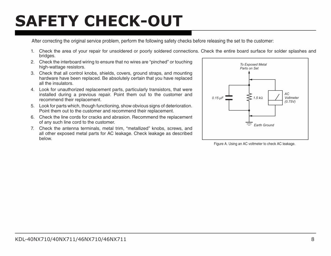
7. Check the antenna terminals, metal trim, “metallized” knobs, screws, and all other exposed metal parts for AC leakage. Check leakage as described below.
To Exposed MetalParts on Set
0.15 µF
Earth Ground
ACVoltmeter(0.75V)
Figure A. Using an AC voltmeter to check AC leakage.
KDL-40NX710/40NX711/46NX710/46NX711 9
SAFETy ChECk-OUT
lEakagE tEStThe AC leakage from any exposed metal part to earth ground and from all exposed metal parts to any exposed metal part having a return to chassis, must not exceed 0.5 mA(500 microamperes). Leakage current can be measured by any one of three methods.
1. A commercial leakage tester, such as the Simpson 229 or RCA WT-540A. Follow the manufacturers’ instructions to use these instructions.
2. A battery-operated AC milliampmeter. The Data Precision 245 digital multimeter is suitable for this job.
3. Measuring the voltage drop across a resistor by means of a VOM or battery-operated AC voltmeter. The “limit” indication is 0.75 V, so analog meters must have an accurate low voltage scale.
The Simpson’s 250 and Sanwa SH-63TRD are examples of passive VOMs that are suitable. Nearly all battery-operated digital multimeters that have a 2 VAC range are suitable (see Figure A).
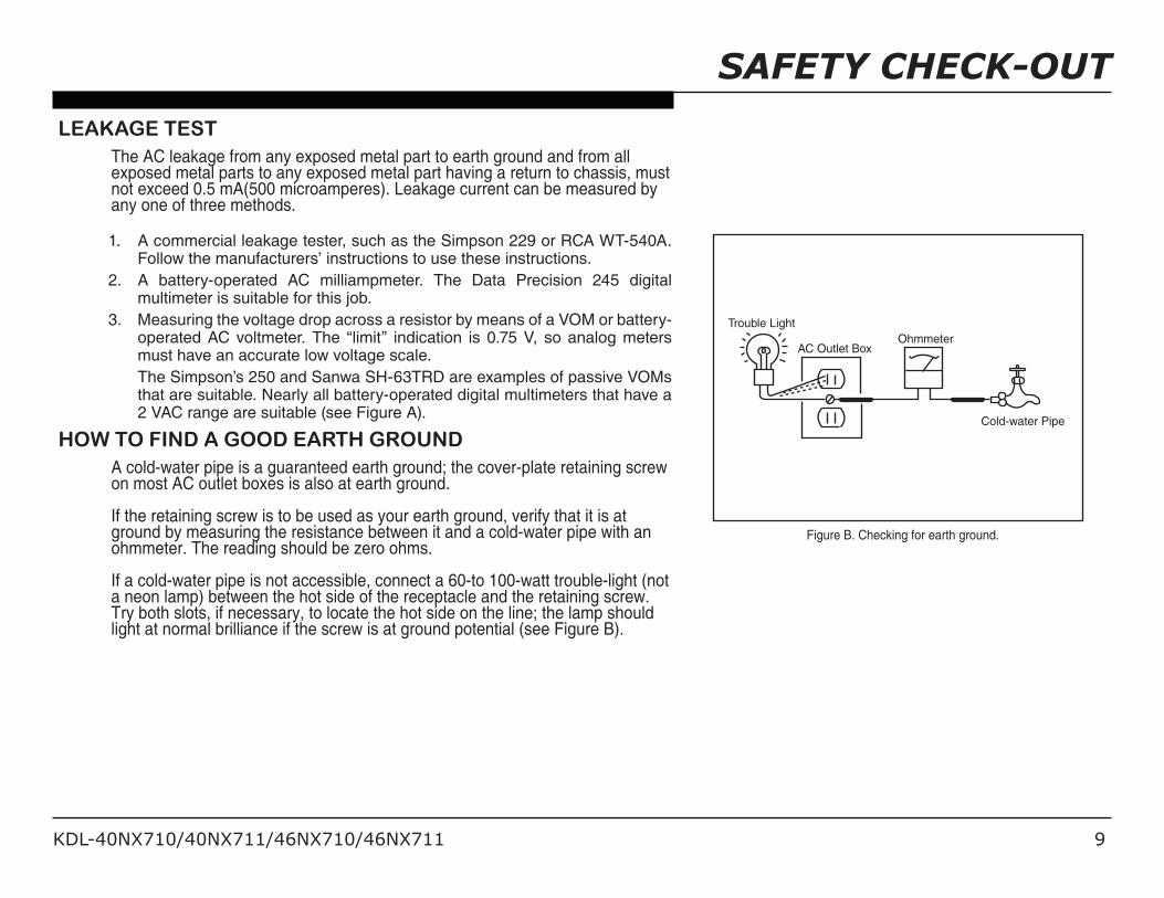
HoW to find a good EartH groundA cold-water pipe is a guaranteed earth ground; the cover-plate retaining screw on most AC outlet boxes is also at earth ground.
If the retaining screw is to be used as your earth ground, verify that it is at ground by measuring the resistance between it and a cold-water pipe with an ohmmeter. The reading should be zero ohms.
If a cold-water pipe is not accessible, connect a 60-to 100-watt trouble-light (not a neon lamp) between the hot side of the receptacle and the retaining screw. Try both slots, if necessary, to locate the hot side on the line; the lamp should light at normal brilliance if the screw is at ground potential (see Figure B).
Trouble Light
AC Outlet BoxOhmmeter
Cold-water Pipe
Figure B. Checking for earth ground.
KDL-40NX710/40NX711/46NX710/46NX711 10
SELFDIAGNOSISFUNCTIONSSElf diagnoSiS funCtion
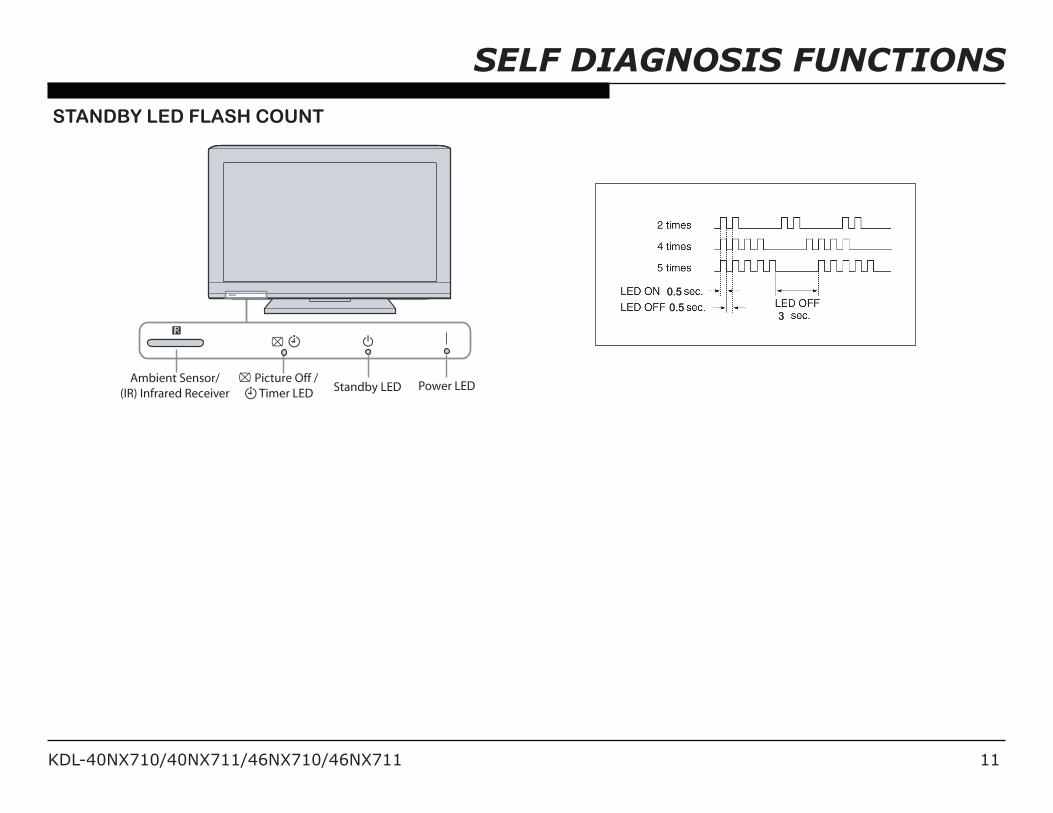
The units in this manual contain a self-diagnostic function. If an error occurs, the STANDBY LED will automatically begin to flash. The number of times the LED flashes translates to a probable source of the problem. A definition of the STANDBY LED flash indicators is listed in the instruction manual for the user’s knowledge and reference. If an error symptom cannot be reproduced, the remote commander can be used to review the failure occurrence data stored in memory to reveal past problems and how often these problems occur.
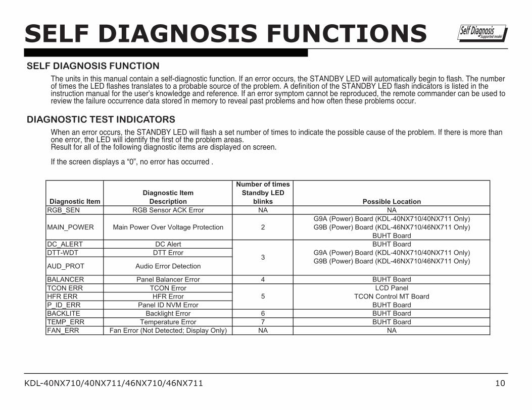
diagnoStiC tESt indiCatorSWhen an error occurs, the STANDBY LED will flash a set number of times to indicate the possible cause of the problem. If there is more than one error, the LED will identify the first of the problem areas. Result for all of the following diagnostic items are displayed on screen.
If the screen displays a “0”, no error has occurred .
Diagnostic ItemDiagnostic Item
Description
Number of times Standby LED
blinks Possible LocationRGB_SEN RGB Sensor ACK Error NA NA
MAIN_POWER Main Power Over Voltage Protection 2G9A (Power) Board (KDL-40NX710/40NX711 Only)G9B (Power) Board (KDL-46NX710/46NX711 Only)
BUHT BoardDC_ALERT DC AlertDTT-WDT DTT Error
AUD_PROT Audio Error Detection
BALANCER Panel Balancer Error 4 BUHT BoardTCON ERR TCON ErrorHFR ERR HFR ErrorP_ID_ERR Panel ID NVM ErrorBACKLITE Backlight Error 6 BUHT BoardTEMP_ERR Temperature Error 7 BUHT BoardFAN_ERR Fan Error (Not Detected; Display Only) NA NA
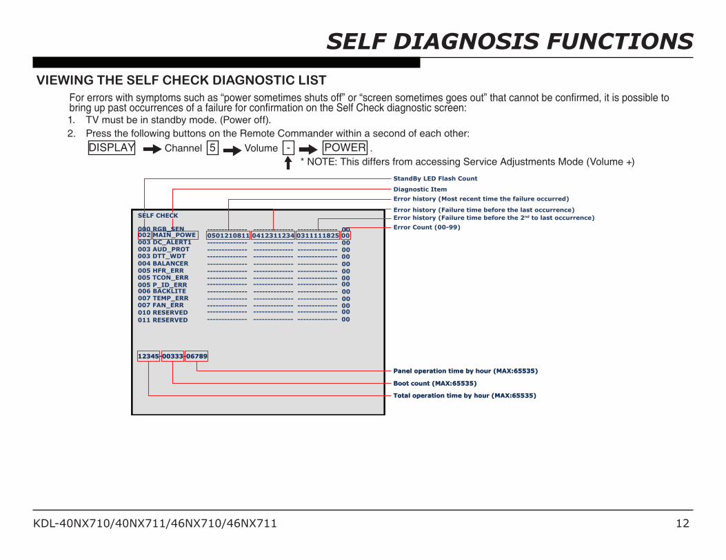
ViEWing tHE SElf CHECk diagnoStiC liStFor errors with symptoms such as “power sometimes shuts off” or “screen sometimes goes out” that cannot be confirmed, it is possible to bring up past occurrences of a failure for confirmation on the Self Check diagnostic screen:1. TV must be in standby mode. (Power off).2. Press the following buttons on the Remote Commander within a second of each other: DISPLAY Channel 5 Volume - POWER . * NOTE: This differs from accessing Service Adjustments Mode (Volume +)
Error history (Most recent time the failure occurred)
Error history (Failure time before the last occurrence)Error history (Failure time before the 2nd to last occurrence)
Error Count (00-99)
KDL-40NX710/40NX711/46NX710/46NX711 13
ClEaring tHE SElf CHECk diagnoStiC liStSince the diagnostic results displayed on the screen are not automatically cleared, always check the self-diagnostic screen after you have completed the repairs to be sure you have cleared the result display to “0”.1. To clear the Error history and Error count: Press the Channel 8 Channel 0 .2. To clear the Panel operation time: Press the Channel 7 Channel 0 .
Exiting tHE SElf CHECk diagnoStiC SCrEEn1. To exit the Self Diagnostic screen, turn off the power to the TV by pressing the POWER button on the remote or the POWER button on
the TV.
SELF DIAGNOSIS FUNCTIONS
KDL-40NX710/40NX711/46NX710/46NX711 14
Components not identifi ed by a part number or description are not stocked because they are seldom required for routine service.
The component parts of an assembly are indicated by the reference numbers in the far right column of the parts list and within the dotted lines of the diagram.
* Items marked with an asterisk are not stocked since they are seldom required for routine service. Expect some delay when ordering these components.
NOTE: Les composants identifi es per un trame et une marque ! sont critiques pour la securite. Ne les remplacer que par une piece portant le numero specifi e.
NOTE: The components identifi ed by shading and ! mark are critical for safety. Replace only with part number specifi ed.
NOTE: The components identifi ed by a red outline and a mark contain confi dential information. Specifi c instructions must be adhered to whenever these components are repaired and/or replaced. See Appendix A: Encryption Key Components in the back of this manual.
SEC 1. DISASSEMBLY/PART NUMBER INFORMATION
REF. NO. PART NO. DESCRIPTION [ASSEMBLY INCLUDES] REF. NO. PART NO. DESCRIPTION [ASSEMBLY INCLUDES]
3 4-256-168-01 HEAD, STAND (ML) 4 3-452-815-01 SCREW, +PSW M5X20 (SCREWS TO ATTACH TABLE-TOP STAND TO LCD TV) For product protection and safety reasons, Sony strongly recommends that you use the screws provided with the TV CAUTION: These screws cannot be used to secure the TV to the Wall Mount Brackets
3-452-815-01 SCREW, +PSW M5X20
Soft Cloth
C
1
2
4
3
B
A
1-1. TABLE-TOP STAND ASSEMBLY REMOVAL
CAUTION: Use care when handling the TV. Correct hand placement while carrying the TV is very important for safety and to avoid damaging the panel. For more information Refer to ”Special Handling Instructions When Replacing the LCD Panel Assembly” on page 6
A Remove 3 screws from Table-Top Stand AssemblyB Lift up TV set to detach from Table-Top Stand Assembly
C Gently place the LCD Panel Assembly face down onto a soft clothCAUTION: Refer to “Special Handling Instructions When Replacing the LCD Panel Assembly” on page 6
(Check the Sony Electronics Service Information website for any additional service related issues for this model.)
DISASSEMBLY/PART NUMBER INFORMATIONNOTE: Les composants identifi es per un trame et une marque ! sont critiques pour la securite. Ne les remplacer que par une piece portant le numero specifi e.
NOTE: The components identifi ed by shading and ! mark are critical for safety. Replace only with part number specifi ed.
NOTE: The components identifi ed by a red outline and a mark contain confi dential information. Specifi c instructions must be adhered to whenever these components are repaired and/or replaced. See Appendix A: Encryption Key Components in the back of this manual.
REF. NO. PART NO. DESCRIPTION [ASSEMBLY INCLUDES]
1-2. REAR COVER, BEZEL BOTTOM, SPEAKERS AND SWITCH UNIT REMOVAL
A Remove 1 screw from AC Cover to detach from Rear CoverB Remove 2 screws from Rear Cover to detach from Bottom FrameC Remove screws from Rear Cover to detach from LCD Panel Assembly
9 from KDL-40NX710/40NX711 Only
11 from KDL-46NX710/46NX711 OnlyD Lift up Switch Unit and disconnect 1 connector to remove from LCD Panel Assembly
DISASSEMBLY/PART NUMBER INFORMATIONNOTE: Les composants identifi es per un trame et une marque ! sont critiques pour la securite. Ne les remplacer que par une piece portant le numero specifi e.
NOTE: The components identifi ed by shading and ! mark are critical for safety. Replace only with part number specifi ed.
NOTE: The components identifi ed by a red outline and a mark contain confi dential information. Specifi c instructions must be adhered to whenever these components are repaired and/or replaced. See Appendix A: Encryption Key Components in the back of this manual.
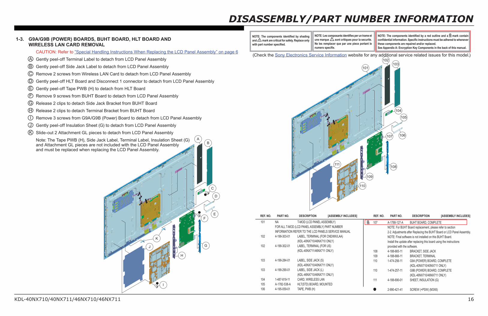
1-3. G9A/G9B (POWER) BOARDS, BUHT BOARD, HLT BOARD AND WIRELESS LAN CARD REMOVAL
REF. NO. PART NO. DESCRIPTION [ASSEMBLY INCLUDES]
107 A-1788-127-A BUHT BOARD, COMPLETE NOTE: For BUHT Board replacement, please refer to section 2-2. Adjustments after Replacing the BUHT Board or LCD Panel Assembly. NOTE: Final software is not installed on this BUHT Board. Install the update after replacing this board using the instructions provided with the software. 108 4-188-665-11 BRACKET, SIDE JACK 109 4-188-666-11 BRACKET, TERMINAL 110 1-474-256-11 G9A (POWER) BOARD, COMPLETE (KDL-40NX710/40NX711 ONLY) 110 1-474-257-11 G9B (POWER) BOARD, COMPLETE (KDL-46NX710/46NX711 ONLY) 111 4-188-690-01 SHEET, INSULATION (G)
2-990-421-41 SCREW (+PSW) (M3X6)
101 NA T-MOD (LCD PANEL ASSEMBLY) FOR ALL T-MOD (LCD PANEL ASSEMBLY) PART NUMBER INFORMATION REFER TO THE LCD PANELS SERVICE MANUAL 102 4-199-303-01 LABEL, TERMINAL (FOR CND/MX/LAA) (KDL-40NX710/46NX710 ONLY) 102 4-199-302-01 LABEL, TERMINAL (FOR US) (KDL-40NX711/46NX711 ONLY) 103 4-199-284-01 LABEL, SIDE JACK (S) (KDL-40NX710/40NX711 ONLY) 103 4-199-290-01 LABEL, SIDE JACK (L) (KDL-46NX710/46NX711 ONLY) 104 1-487-819-11 CARD, WIRELESS LAN 105 A-1782-538-A HLT(STD) BOARD, MOUNTED 106 4-195-059-01 TAPE, PWB (H)
REF. NO. PART NO. DESCRIPTION [ASSEMBLY INCLUDES]
107 106
105
108
109
111
110
104
103102
101
FE
D
G
H
J
K
I
C
BA
CAUTION: Refer to ”Special Handling Instructions When Replacing the LCD Panel Assembly” on page 6A Gently peel-off Terminal Label to detach from LCD Panel AssemblyB Gently peel-off Side Jack Label to detach from LCD Panel AssemblyC Remove 2 screws from Wireless LAN Card to detach from LCD Panel AssemblyD Gently peel-off HLT Board and Disconnect 1 connector to detach from LCD Panel AssemblyE Gently peel-off Tape PWB (H) to detach from HLT BoardF Remove 9 screws from BUHT Board to detach from LCD Panel AssemblyG Release 2 clips to detach Side Jack Bracket from BUHT BoardH Release 2 clips to detach Terminal Bracket from BUHT BoardI Remove 3 screws from G9A/G9B (Power) Board to detach from LCD Panel AssemblyJ Gently peel-off Insulation Sheet (G) to detach from LCD Panel AssemblyK Slide-out 2 Attachment GL pieces to detach from LCD Panel Assembly
Note: The Tape PWB (H), Side Jack Label, Terminal Label, Insulation Sheet (G) and Attachment GL pieces are not included with the LCD Panel Assembly and must be replaced when replacing the LCD Panel Assembly.
(Check the Sony Electronics Service Information website for any additional service related issues for this model.)
DISASSEMBLY/PART NUMBER INFORMATIONNOTE: Les composants identifi es per un trame et une marque ! sont critiques pour la securite. Ne les remplacer que par une piece portant le numero specifi e.
NOTE: The components identifi ed by shading and ! mark are critical for safety. Replace only with part number specifi ed.
NOTE: The components identifi ed by a red outline and a mark contain confi dential information. Specifi c instructions must be adhered to whenever these components are repaired and/or replaced. See Appendix A: Encryption Key Components in the back of this manual.
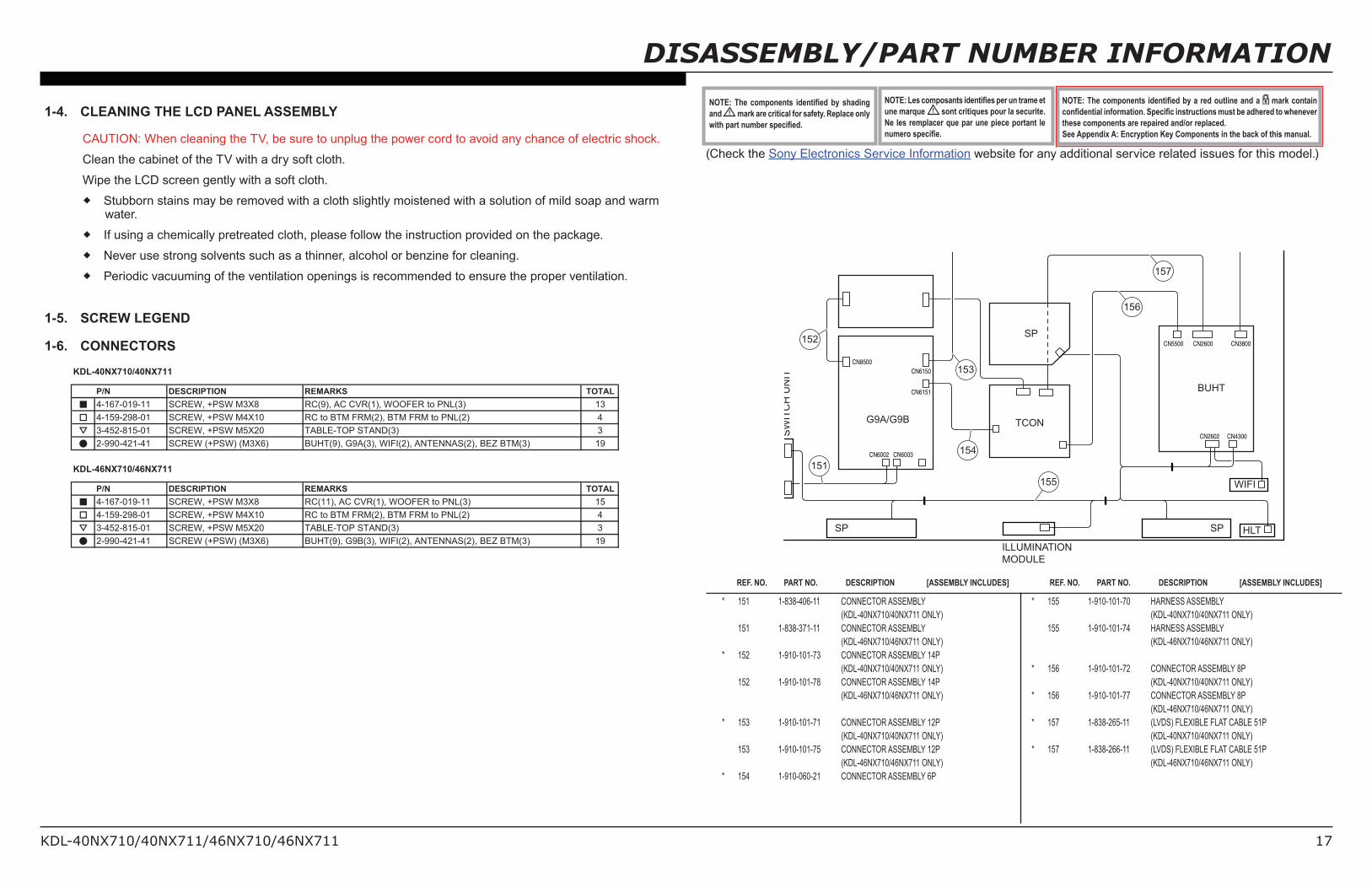
1-4. CLEANING THE LCD PANEL ASSEMBLY
CAUTION: When cleaning the TV, be sure to unplug the power cord to avoid any chance of electric shock.
Clean the cabinet of the TV with a dry soft cloth.
Wipe the LCD screen gently with a soft cloth.
Stubborn stains may be removed with a cloth slightly moistened with a solution of mild soap and warm water.
If using a chemically pretreated cloth, please follow the instruction provided on the package.
Never use strong solvents such as a thinner, alcohol or benzine for cleaning.
Periodic vacuuming of the ventilation openings is recommended to ensure the proper ventilation.
1-5. SCREW LEGEND
1-6. CONNECTORS
REF. NO. PART NO. DESCRIPTION [ASSEMBLY INCLUDES] REF. NO. PART NO. DESCRIPTION [ASSEMBLY INCLUDES]
Within each Service Menu are Categories and data information.
CHASSIS SERVICE000 CXD2813R000 H_DET_NOSIG_CNT 1
Category number
Item number
Item name
Category name
Item Data Value
Sample Chassis Service Menu
KDL-40NX710/40NX711/46NX710/46NX711 23
SERvICE ADjUSTMENTS
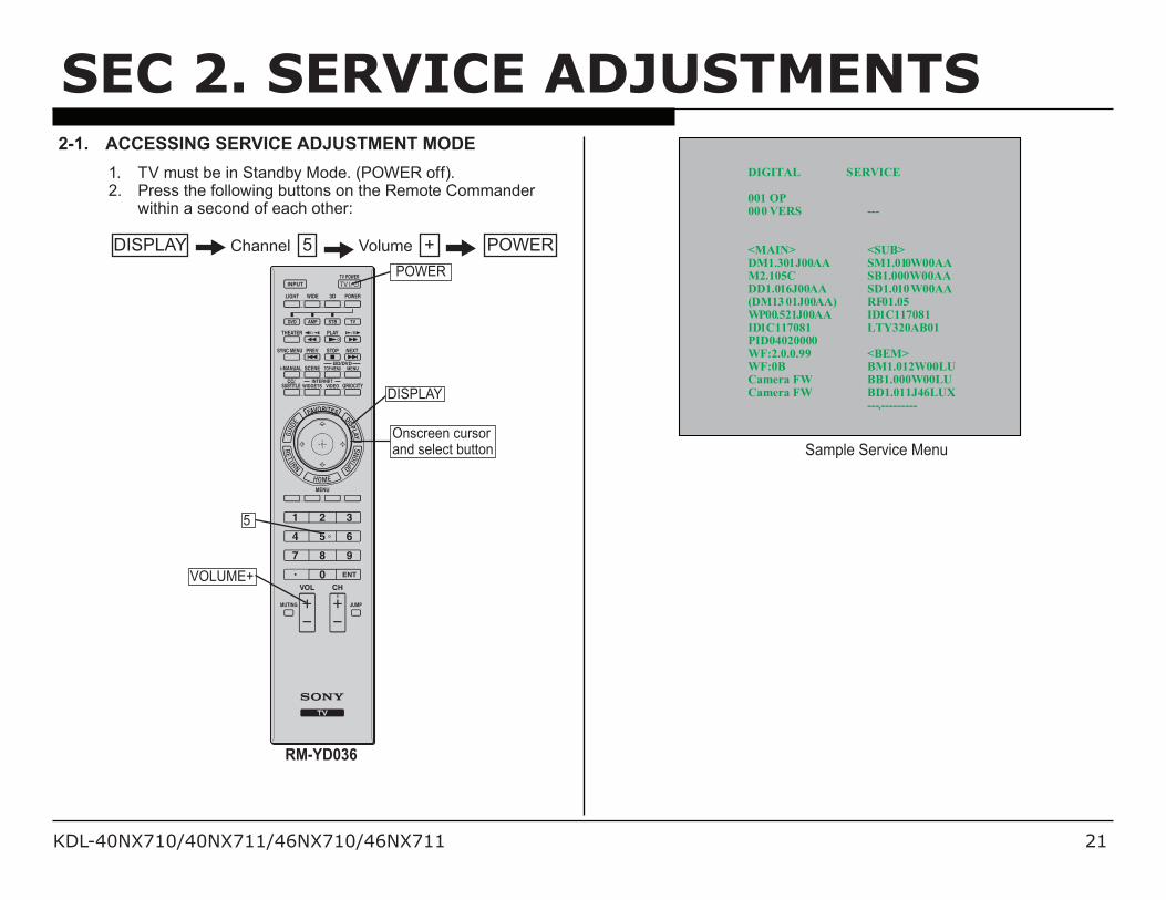
2-1-2. USING THE REMOTE COMMANDER TO VIEW OR CHANGE SERVICE DATAUse the buttons on the Remote Commander to access the Service Menu items and adjust the Data Values.
DISPLAY Channel 5 Volume + POWER
4. To change the Category, press 2 to move to the Next Category orpress 5 to go back to the Previous Category.
Note: Pressing 2 or 5 only changes the Categories within the Service Menu displayed.
5. To change the adjustment item, press 1 to move to the Next Item or 4 to go back to the Previous Item.
6. To change the Data Value, press 3 to increase the Data Value or 6 to decrease the Data Value.
7. Press MUTING then press 0 to WRITE (Save) the changes.8. To exit service mode, press HOME or turn the TV power off.
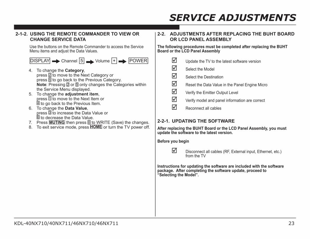
2-2. ADjUSTMENTS AFTER REPLACING THE BUHT BOARD OR LCD PANEL ASSEMBLY
The following procedures must be completed after replacing the BUHT Board or the LCD Panel Assembly
þ Update the TV to the latest software version
þ Select the Model
þ Select the Destination
þ Reset the Data Value in the Panel Engine Micro
þ Verify the Emitter Output Level
þ Verify model and panel information are correct
þ Reconnect all cables
2-2-1. UPDATING THE SOFTWAREAfter replacing the BUHT Board or the LCD Panel Assembly, you must update the software to the latest version.
Before you begin
þ Disconnect all cables (RF, External input, Ethernet, etc.) from the TV
Instructions for updating the software are included with the software package. After completing the software update, proceed to “Selecting the Model”.
KDL-40NX710/40NX711/46NX710/46NX711 24
SERvICE ADjUSTMENTS
2-2-2. SELECTING THE MODELAfter replacing the BUHT Board or LCD Panel Assembly, go into Service Mode to set the Model data value.
1. TV must be in standby mode. (Power off).2. Access Service Mode. Press the following buttons on the Remote Commander
within a second of each other:
DISPLAY Channel 5 Volume + POWER
3. Display the DIGITAL Service Menu. NOTE: There are 4 Service Menus for this model, DIGITAL,
CHASSIS, SUB, and PEM. If the DIGITAL Service Menu is not displayed, press jUMP or OPTIONS on the Remote Commander.
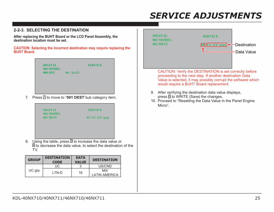
2-2-3. SELECTING THE DESTINATIONAfter replacing the BUHT Board or the LCD Panel Assembly, the destination location must be set.
CAUTION: Selecting the incorrect destination may require replacing the BUHT Board.
DIGITAL SERVICE002 MODEL000 SEG 04 : 2a-2.5
7. Press 1 to move to “001 DEST”sub category item.
DIGITAL SERVICE002 MODEL001 DEST 03: UC (UC grp)
8. Using the table, press 3 to increase the data value or 6 to decrease the data value, to select the destination of the TV.
GROUPDESTINATION
CODEDATAVALUE
DESTINATION
UC 3 US/CND
LTN-D 16 MX/LATIN AMERICA
UC grp
DIGITAL SERVICE002 MODEL001 DEST 03: UC (UC grp)
Data Value
Destination
CAUTION: Verify the DESTINATION is set correctly before proceeding to the next step. If another destination Data Value is selected, it may possibly corrupt the software which would require a BUHT Board replacement.
9. After verifying the destination data value displays, press 0 to WRITE (Save) the changes.
10. Proceed to “Resetting the Data Value in the Panel Engine Micro”.
KDL-40NX710/40NX711/46NX710/46NX711 26
SERvICE ADjUSTMENTS
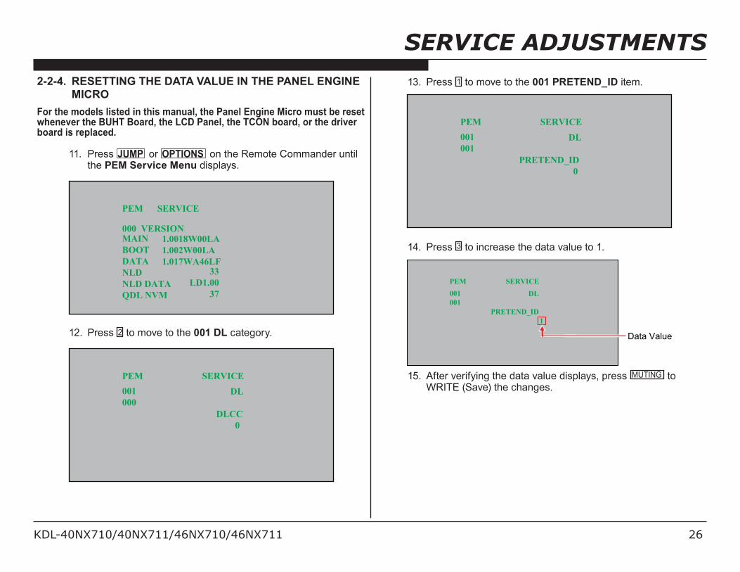
2-2-4. RESETTING THE DATA VALUE IN THE PANEL ENGINE MICRO
For the models listed in this manual, the Panel Engine Micro must be reset whenever the BUHT Board, the LCD Panel, the TCON board, or the driver board is replaced.
11. Press jUMP or OPTIONS on the Remote Commander until the PEM Service Menu displays.
PEM SERVICE
000 VERSION MAIN BOOT DATA NLD NLD DATA QDL NVM
33LD1.00
37
1.0018W00LA1.002W00LA1.017WA46LF
12. Press 2 to move to the 001 DL category.
PEM SERVICE001000
DL
DLCC 0
13. Press 1 to move to the 001 PRETEND_ID item.
PEM SERVICE001001
DL
PRETEND_ID 0
14. Press 3 to increase the data value to 1.
PEM SERVICE001001
DL
PRETEND_ID 1
Data Value
15. After verifying the data value displays, press MUTING to WRITE (Save) the changes.
KDL-40NX710/40NX711/46NX710/46NX711 27
SERvICE ADjUSTMENTS
16. Press 2 until the 004 TCON_CHANGED category displays.
PEM SERVICE004000
TCON_CHANGED
DATA_TRANS_SET 0
17. For the DATA_TRANS_SET item, press 3 to increase the data value to 1.
PEM SERVICE004000
TCON_CHANGED
DATA_TRANS_SET 1
Data Value
18. Press 1 until the 001 DATA_TRANS_EXE item displays.
PEM SERVICE004001
TCON_CHANGED
DATA_TRANS_EXE 0
KDL-40NX710/40NX711/46NX710/46NX711 28
SERVICE ADJUSTMENTS
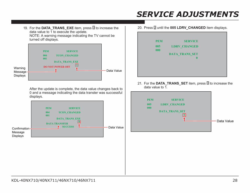
19. For the DATA_TRANS_EXE item, press 3 to increase the data value to 1 to execute the update.
NOTE: A warning message indicating the TV cannot be turned off displays.
PEM SERVICE004001
TCON_CHANGED
DATA_TRANS_EXE 1
DO NOT POWER OFFData Value
Warning Message Displays
After the update is complete, the data value changes back to 0 and a message indicating the data transter was successful displays.
PEM SERVICE004001
TCON_CHANGED
DATA_TRANS_EXE 0
DATA TRANSFER SUCCESS Data ValueConfirmation
Message Displays
20. Press 2 until the 005 LDRV_CHANGED item displays.
PEM SERVICE005000
LDRV_CHANGED
DATA_TRANS_SET 0
21. For the DATA_TRANS_SET item, press 3 to increase the data value to 1.
PEM SERVICE005000
LDRV_CHANGED
DATA_TRANS_SET 1
Data Value
KDL-40NX710/40NX711/46NX710/46NX711 29
SERvICE ADjUSTMENTS
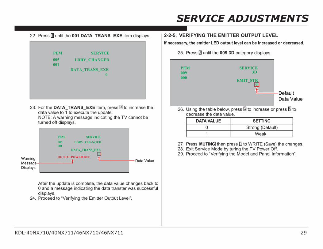
22. Press 1 until the 001 DATA_TRANS_EXE item displays.
PEM SERVICE005001
LDRV_CHANGED
DATA_TRANS_EXE 0
23. For the DATA_TRANS_EXE item, press 3 to increase the data value to 1 to execute the update.
NOTE: A warning message indicating the TV cannot be turned off displays.
PEM SERVICE005001
LDRV_CHANGED
DATA_TRANS_EXE 1
Data ValueDO NOT POWER OFFWarning
Message Displays
After the update is complete, the data value changes back to 0 and a message indicating the data transter was successful displays.
24. Proceed to “Verifying the Emitter Output Level”.
2-2-5. VERIFYING THE EMITTER OUTPUT LEVELIf necessary, the emitter LED output level can be increased or decreased.
25. Press 2 until the 009 3D category displays.
PEM SERVICE009000 EMIT_STR
3D
0
DefaultData Value
26. Using the table below, press 3 to increase or press 6 to decrease the data value.
DATA VALUE SETTING 0 Strong (Default) 1 Weak
27. Press MUTING then press 0 to WRITE (Save) the changes.28. Exit Service Mode by turing the TV Power Off.29. Proceed to “Verifying the Model and Panel Information”.
KDL-40NX710/40NX711/46NX710/46NX711 30
SERvICE ADjUSTMENTS
2-2-6. VERIFYING THE MODEL AND PANEL INFORMATIONAfter saving the changes to the service data, verify the information.
1. TV must be in standby mode. (Power off).2. Access Service Mode. Press the following buttons on the Remote Commander
within a second of each other:
DISPLAY Channel 5 Volume + POWER
3. Display the DIGITAL Service Menu. NOTE: There are 3 Service Menus for this model, DIGITAL,
CHASSIS, and SUB. If the DIGITAL Service Menu is not displayed, press jUMP or OPTIONS on the Remote Commander.
4. Using the table, verify the Model ID and the Product ID match the information in the Service Menu.
Model Name Model ID Product IDKDL-40NX710 86d731b1 0cb20000KDL-40NX710 86d731b1 40b20000KDL-40NX711 86d731b1 0cb20000KDL-46NX710 86d731b2 0cb20000KDL-46NX710 86d731b2 40b20000KDL-46NX711 86d731b2 0cb20000
5. Exit Service Mode by pressing HOME or turn the TV power off.
6. Proceed to “Reconnecting All Cables”.
2-2-7. RECONNECTING ALL CABLESAfter completing the changes to service mode, reconnect all the cables (RF, External input, Ethernet, etc.) to the TV then verify the TV set picture.
KDL-40NX710/40NX711/46NX710/46NX711 31
SERvICE ADjUSTMENTS
2-3. WHITE BALANCE ADjUSTMENTSBy default the White Balance Adjustments are set for optimal viewing. If White Balance Adjustments are requested, the data is located on the Panel Engine Micro (PEM) Service Menu.
1. TV must be in Standby Mode. (POWER Off).2. Press the following buttons on the Remote Commander
within a second of each other: DISPLAY Channel 5 Volume + POWER .
3. The DIGITAL Service Menu displays. NOTE: There are 4 Service Menus for these models,
7. After completing all White Balance Adjustments, press MUTING then press 0 to WRITE (Save) the changes.
2-4. RESETTING THE TV TO FACTORY CONDITIONUse the following instructions to restore the User Adjustments and Channel Memory settings to the preset factory conditions.
1. While holding down the on the Remote Commander, press the POWER button on the TV Switch Unit of the set.
The set restarts and displays the Initial Setup screen. This may take several minutes.
2-4-1. RESETTING THE TV TO FACTORY CONDITION USING SERVICE MODE1. TV must be in Standby Mode. (POWER off).2. Press the following buttons on the Remote Commander
within a second of each other: DISPLAY Channel 5 Volume + POWER .
3. If necessary, press JUMP or OPTIONS to go to DIGITAL mode.
4. Press 8 . “SERVICE” changes to green RST. 5. Press MUTING . RST executes the command and displays EXE.6. Press 0 . EXE-RST displays green, then red indicating the TV is
writing the data.7. When the process is complete the green SERVICE text
displays and the LED display as shown below:
TIMER Standby POWERTIMER Standby POWER8. Cycle AC Power (Unplug and Plug AC Cord from the AC
Outlet). 9. The set restarts and displays the Initial Setup screen.