Sør-Norge Aluminium AS 2.3 Electro technical specification rev 8.5x Side 1 av 30 Topic 1 – Purchasing terms Specification 2.3 – Electro Technical Specification Publisher Unit TEK Date: 10.01.2018 by Torstein Fykse Document No.: 2.3 Revision No.: 8.5 Valid From: 15.01.2018 Table of Contents: 1. GENERAL INFORMATION ABOUT BUYER’S ELECTRICAL INSTALLATION ................................ 2 2. NORWEGIAN REGULATIONS, DIRECTIVES AND PARTICULAR REQUIREMENTS...................... 5 3. WORKMANSHIP REQUIREMENTS ...................................................................................... 11 4. REQUIREMENTS FOR DOCUMENTATION AND TRAINING ................................................... 19 5. BUYERS STANDARD (MATERIAL LIST) ................................................................................ 22 Buyer in this document is Sør-Norge Aluminium AS.
Transcript
Sør-Norge Aluminium AS
2.3 Electro technical specification rev 8.5x Side 1 av 30
4. REQUIREMENTS FOR DOCUMENTATION AND TRAINING ................................................... 19
5. BUYERS STANDARD (MATERIAL LIST) ................................................................................ 22
Buyer in this document is Sør-Norge Aluminium AS.
Sør-Norge Aluminium AS
2.3 Electro technical specification rev 8.5x Side 2 av 30
Electromagnetic fields
Electromagnetic fields shall conform to the limits stipulated in directive 2013/35/EU.
The electromagnetic fields are created by the DC power to the reduction cells inside and near the
potroom.
The magnetic fields are and will be affected by steel parts brought into the field. Steel parts inside the
magnetic fields will be affected by mechanical forces. Seller shall include this effect in the functionality
requirement of equipment / installations delivered.
The electromagnetic fields created by the DC power busbars between potroom and rectifier buildings,
and AC power supply to the rectifiers shall be calculated by Seller of this equipment as part of the
delivery. The rectifier Seller shall establish the magnetic fields DC and AC (harmonic) inside the start
section of the potroom (between first / last cell and end wall of potroom building).
Note: Maximum exposure for authorized personnel is 2T (20,000 G).
Areas where high-intensity static magnetic fields (0-1 Hz) occur shall be marked on drawings and with
warning signs at two levels:
• 3 mT (30 G): Access for authorized personnel only
• 0.5 mT (5 G): No access for persons with pacemakers or other electronic implants.
By emergency cut out of the potline or outage of power supply (DC supply) the magnetic field will
change from 100% to 0% during the electrical time constant for the potline. It is the responsibility of
Seller to include this effect in the design (induced voltage and current in circuits in nearby current
loops).
1. GENERAL INFORMATION ABOUT BUYER’S ELECTRICAL INSTALLATION
Stationary and transient voltage and frequency deviations shall be in accordance with local authority
regulations, grid owner requirements and the requirements given in IEC.
The main figures are:
• Stationary voltage deviations can be up to +5 %/-5 %
• Maximum transient voltage deviation: + 10 / –10 %
Consumer side shall not cause more voltage transients than maximum 3 % drop at the main busbars
and 15 % at consumer terminals.
Sør-Norge Aluminium AS
2.3 Electro technical specification rev 8.5x Side 3 av 30
1.1 High Voltage Installation
Voltage above 1000V AC, and above 1500V DC.
300kV.
The Main Supply for Buyer has a voltage of 300kV which is supplied from the central power grid.
The central power grid consists of two lines from Blåfalli Switching Station and a subsea cable from
Stord.
24kV.
The unregulated supply has a voltage of 24kV. This supplies the rectifier and the regulating
transformers. The output to SKL/KE is also connected here. The neutral point is insulated.
Maximum Ik is 31.5kA.
Phase Compensating
2 ea. capacitor batteries of 65MVAr are connected to 24kV unregulated distributions.
The capacitor batteries are switched in through 2 steps. When connecting, powerful switching
transients occur, in particular at the 400V level.
20kV
The general plant supply has a voltage of 20kV, which normally is supplied from one of two 30MVA
regulating transformers. The neutral point is insulated.
The Buyer’s transformer stations are supplied with regular 20kV via ring cables from the plant supply in
20kV buildings.
The Maximum Ik for 20kV in the transformer station is 12kA.
Short circuit yield can be stated for each item on request from the Buyer’s electro department.
6kV
Some motors to air compressors, in addition to electro boiler for heating of water are executed for
6kV. IT distributing system.
Sør-Norge Aluminium AS
2.3 Electro technical specification rev 8.5x Side 4 av 30
1.2 Low Voltage Installations
Voltage below 1000V AC and below 1500V DC.
There are low voltage switchboards in the transformer stations which are supplied from distribution
transformers with a ratio of 20/0.400 kV or 20/0.690kV.
In general, 3 phase 400V is used as distribution system (TNCS-System) for motors and other 3-phase
loads. 230V direct connection between Phase and N is used for lighting.
As an exception, 3x690V is used for larger motors and heating installations. IT distributing system.
Control voltage (usually 230V AC) is supplied by a control power transformer (secondary side). The
control power transformer (primary side) is connected to 400v (between two phases).
Ground fault monitoring shall be installed on the 230V side when using control power transformers.
For PLC installations, etc., a ground fault alarm shall be presented via the control system. For smaller
installations, a signal lamp indicating ground faults can be installed in the cabinet door.
For local fault message/alarm, the following system is used:
•••• Fault present: Flashing red light, possibly also an acoustic alarm.
•••• Alarm deactivated: Continuous red light.
•••• Fault removed: Light off
For some installations, transferring some or common alarms to the gate guard is also desirable. This
can be done in the current system or agreed separately.
Buyer’s rectifier installation for electrolysis produces some overharmonic oscillations back to the
power grid.
Short circuit performance at the secondary side of the distribution transformer is in the range of 30kA.
This can be stated separately for each point on request from the Buyer’s electro department.
Sør-Norge Aluminium AS
2.3 Electro technical specification rev 8.5x Side 5 av 30
2. NORWEGIAN REGULATIONS, DIRECTIVES AND PARTICULAR REQUIREMENTS
2.1 General All assembly and installation shall be performed in accordance with current publications from DSB:
• Regulation on safety at work on and operating electrical installations, with instructions. (FSE)
• Regulation on Electrical Low Voltage Installations, with instructions.
• Regulations on Electrical Supply Installations. (FEF)
• Regulations on qualifications for electrical professionals, with instructions. (FKE)
Before the work commences, Seller shall send a message to the Buyer’s expert manager of operations.
After delivery, the installation shall be CE-marked in accordance with current directives.
• Machine Directive
• Low Voltage Directive
• EMC Directive
Plants and products shall be delivered with the conformity declaration. The necessary verification
documents shall be delivered with the conformity declaration. Ref. NEK 400-6.
Unless other written agreements have been made, all material shall be delivered in accordance with
the Buyer’s standard (item 5).
If the work has been performed in conflict with current regulations or Buyer’s specifications, the error
must be corrected. Seller shall cover all costs in connection with correcting such errors.
Sør-Norge Aluminium AS
2.3 Electro technical specification rev 8.5x Side 6 av 30
2.1.1 Workmanship requirements
2.1.1.12.1.1.12.1.1.12.1.1.1 Energy efficiencyEnergy efficiencyEnergy efficiencyEnergy efficiency
All main equipment, buildings and utilities shall be designed with regards to energy efficiency. The
contract object shall be optimized for minimum energy consumption while performing its given task.
Items that shall be implemented during design of the contract object includes:
• For single loads / machines with greater consumption than 100,000 kWh / year, there should be
installed an energy meter.
• Lighting control by movement sensors or timers for area lighting.
• Where it is appropriate, LED should be used as light sources.
• Automatic shut off of general heating / cooling systems, trace heating etc by temperature sensors.
• Energy recovery in drives for lifting and hoisting applications.
• Automatic shut off of pumps, fans, vacuum cleaners and other utilities when not needed.
• At systems with frequent start / stop of engines, it must be installed soft starters.
• Waste heat recovery shall be considered for all production equipment.
• Compressed air consumption shall be minimized.
• Electric cable and bus bar dimensioning shall be done with emphasis on minimum power loss.
2.1.1.2 Electrolysis
In the Electrolysis it is important that the earth potential is not exposed due to electrical hazards that
may occur.
In faulty situations, reinforcement in concrete structures may have a voltage of several hundred volts!
All equipment installed in the electrolysis or in connection with concrete structures must therefore be
installed insulated from reinforcement in concrete structures.
Insulation details around the assembly of all equipment must be approved by Electrical Competent
Operation Manager.
2.1.2 Codes and standards
The list of codes and standards provided below cover the most frequently used references for this
specification.
This list is not complete. It is the responsibility of Seller to conform to the appropriate national and
international standards according to the contract object.
List of Electrical/Automation codes and standards
Doc. No. Title
FEF 2006 Forskrift om elektriske forsyningsanlegg med veiledning
FEL Forskrift om elektriske lavspenningsanlegg
FEF Forskrift om elektriske forsyningsanlegg
FEU Forskrift om elektrisk utstyr
NEK 400:2014 Elektriske lavspenningsinstallasjoner (Electrical Low Voltage Installations)
Sør-Norge Aluminium AS
2.3 Electro technical specification rev 8.5x Side 7 av 30
Doc. No. Title
NEK 420 Elektriske anlegg i eksplosjonsfarlige områder med gass og støv. (Electrical installations in potentially explosive atmospheres with gas and dust)
NEK 440:2015 Stasjonsanlegg over 1 kV (Power installations exceeding 1 kV)
EN 50173 Information Technology – Generic Cabling System
EN 50205 Relays with forcibly guided contacts
IEC 60034 Rotating electrical machines
IEC 60071 Insulation co-ordination
IEC 60076 Power Transformers
IEC 60076-6 Power transformers, Reactors
IEC 60076-7 Power transformers. Loading guide for oil-immersed power transformers
IEC 60076-11 Power transformers. Dry-type transformers
IEC 60146 Semiconductor Converters
IEC 60183 Guidance for the selection of high-voltage A.C. cable systems
IEC 60204-1 Machine safety – electric equipment in machines (equivalent: CENELEC EN 60204-1)
IEC 60204-11 Safety of machinery - Electrical equipment of machines - Part 11: Requirements for HV equipment for voltages above 1 000 VAC or 1 500 VDC and not exceeding 36 kV
IEC 60296 Fluids for electrotechnical applications. Unused mineral insulating oils for transformers and switchgear
IEC 60298 A.C. metal-enclosed switchgear and control gear for rated voltages above 1 kV and up to and including 52 kV
IEC 60331 Tests for electric cables under fire conditions. Circuit integrity
IEC 60332 Tests on electric and optical fibre cables under fire conditions
IEC 60364 Low voltage electrical installations (CENELEC HD 384)
IEC 61439 Low voltage switchgear and control gear assemblies
IEC 60529 Degrees of protection provided by enclosures (IP code)
IEC 60584-1 Thermocouples EMF specifications and tolerances
IEC 60617 Graphical symbols for diagrams
IEC 60694 Common clauses for high-voltage switchgear and control gear standards
IEC60794 Optical fiber cables
Sør-Norge Aluminium AS
2.3 Electro technical specification rev 8.5x Side 8 av 30
Doc. No. Title
IEC 60871-1 Shunt capacitors for a.c power systems having a rated voltage above 1000 V. General
IEC 60947-1 Low voltage switchgear and control gear
IEC 61000-6-2 EMC requirements
IEC 61034 Measurement of smoke density of cables burning under defined conditions
IEC 61131-3 Programmable controllers - Part 3: Programming languages
IEC 61140 Protection against electric shock - Common aspects for installation and equipment
IEC 81346 Industrial systems, installations and equipment and industrial products - Structuring principles and reference designations
IEC 61378-1 Converter transformers – Part 1: Transformers for Industrial applications
IEC 61508 Functional safety of electrical/electronic/programmable electronic safety-related systems
IEC 61511 Functional safety. Safety instrumented systems for the process industry sector.
IEC/TR 61641 Enclosed low-voltage switchgear and control gear assemblies - Guide for testing under conditions of arcing due to internal fault
IEC 61800-5-2 Adjustable speed electrical power drive systems. Safety requirements-Functional
IEC 62061 Safety of machinery. Functional safety of safety-related electrical, electronic and programmable electronic control systems
IEC 62271-1 High-voltage switchgear and control gear - Part 1: Common specifications.
IEC 62271-100 High-voltage switchgear and control gear - Part 100: Alternating-current circuit-breakers
IEC 62271-102 High-voltage switchgear and control gear - Part 102: Alternating current disconnectors and earthing switches
IEC 62271-200 High-voltage switchgear and control gear. Part 200: A.C. metal-enclosed switchgear and control gear for rated voltages above 1 kV and up to and including 52 kV.
ISO 3511 Symbolic representation for process measurement control functions and instrumentation
ISO 13849 Part 1 and 2 Safety of machinery. Safety-related parts of control systems.
ISO 14119 Safety of machinery -- Interlocking devices associated with guards --
Principles for design and selection
Sør-Norge Aluminium AS
2.3 Electro technical specification rev 8.5x Side 9 av 30
Doc. No. Title
NFPA 72 National Fire Protection Association Standard 72, National Fire Alarm Code
89/336/EEC EMC Directive
94/9 EC ATEX Directive
2.2 FIRE PROOFING OF CABLE PENETRATIONS AND SECTIONING
2.2.1 Approved fire proofing materials shall be used for fire proofing.
Furthermore, the proofing shall be of the same fire class as the part of the building where the proofing
is being done, when nothing else is prescribed.
2.2.2 Cable Routing.
Cable trays/bridges shall be completed in front of the penetration to insure good proofing and access.
2.2.3 Penetrations for piping and ventilation.
Seller will clarify how penetrations will be proofed.
Joint foam or building foam must not be used.
2.2.4 Marking.
The places where the proofing are done shall be clearly marked in accordance with instructions from
Buyer’s officer in charge.
These shall be marked with information about the fire proofing company and the date of the fire
proofing.
2.3 PAINT WORK, CORROSION PROTECTION, ETC.
2.3.1 This shall be performed in accordance with Specification for surface treatment Part 2.7.
2.3.1.1 Objective.
The norm has been set to obtain a consistent and correct treatment in terms of quality of the surfaces
of aluminum and steel constructions. The implemented systems will cover various environments and
usage areas and any deviations from the norm shall be agreed separately.
2.3.1.2 General.
Buyer will, when necessary, specify the painting system in his inquiry. The products of the specified
manufacturers shall be used unless otherwise described or agreed in writing beforehand.
2.3.1.3 Standards.
Pre-treatment - ISO 8501-1
Chemical purity - ISO 8502-1 to 4
Surface texture - ISO 8503-1 Ry 2 – 3
Adhesion test - ISO 4624
2.3.1.4 Deviations.
Deviations from the norm must be approved in writing from Buyer.
2.3.1.5 Source.
This description is, for the most part, worked out in accordance with Norsk Hydro’s norm EH-015, and
Buyer’s specification for surface treatment Part 2.7
Sør-Norge Aluminium AS
2.3 Electro technical specification rev 8.5x Side 10 av 30
2.3.1.6 Abbreviations.
PUR - Polyurethane
ISO - International Standardizing Organization
TFT - Dry Film Thickness indicated in µm. (micron)
YL - Air quality and supply in the work environment
RAL -
International color code. Buyer’s specification for surface treatment
Part 2.7
Sør-Norge Aluminium AS
2.3 Electro technical specification rev 8.5x Side 11 av 30
3. WORKMANSHIP REQUIREMENTS
3.1 HIGH VOLTAGE
3.1.1 Contactor Cabinet, Control Cabinet, Measuring Fields, etc.
Description in item 3.2.1. with under items shall be followed unless otherwise agreed.
3.1.2 High Voltage Equipment
3.1.2.1 Bus Bars
At delivery of bus bar installations, these shall be adapted to existing grounding systems, and delivered
with appropriate grounding appliances.
Due to the high current in the rail systems, the nuts and bolts on the rails shall be made from stainless
steel A2 80 quality grade.
3.1.2.2 High voltage cabinets / Power Switches / Knife Disconnectors.
Compact cabinets or cabinets for switch trolleys may be used in transformer stations. Short circuit
current for the cabinet shall be minimum Ik=12.5kA. The switches shall be rated In=630A.
In the main power supply installation (24kV), cabinets for switches mounted on switch trolleys with
short circuit current of minimum Ik=31.5kA, and switches for 2500A are required.
In 20kV buildings, switches for regulated 20kV distributions (20kV) shall have minimum short circuit
current of Ik=12.5kA and In=1250A, or as agreed otherwise.
Buyer is planning to use SF6 power switches.
Secondary loops for current transformers should be with short circuit proof cabling and shall not be
routed outside the substation.
Transducers shall be used for routing of secondary current values to control rooms or control stations.
Transducers shall be powered from the control systems auxiliary power supply.
Current and voltage transformers shall be dimensioned for all fault situations in question.
3.1.2.3 High Voltage Cables.
All high voltage cables shall be diffusion sealed, for 24kV, and shall be able to cut test before and after
routing, or as agreed otherwise.
3.1.2.4 End Termination.
Here it may be differentiated between indoor and outdoor types, depending on where the installation
is mounted. Conventional end terminations or terminations of a ”touch proof” type can be used
indoors.
3.1.2.5 Transformers.
To be produced and delivered in accordance with IEC 60076-1 and IEC 60076-2.
All distribution transformers shall have oil insulation, preferably with environment friendly
oil/vegetable oil. Data sheet for the transformer oil shall be referenced in all offers to Buyer.
Dry isolated transformer shall be approved by Buyer in each case.
Accessories shall be agreed for each case. Such accessories shall monitor oil temperature, gas pressure
and oil level.
All transformers shall be delivered with swiveling wheels.
Vector group shall be specified and approved by Buyer.
Sør-Norge Aluminium AS
2.3 Electro technical specification rev 8.5x Side 12 av 30
Distribution transformers have normal vector group DyN5.
The temperature indicator on the transformer shall be readable from the inspection point. All
transformers shall be mounted with signs indicating all substantial transformer performances, volume
and weights. All signs and indicators shall be readable when the transformer is in operation, without
endangering the personnel.
For distribution transformers that do not have standard performance, and power transformers rated at
over 1600kVA, a special agreement is required.
Short circuit performance at the secondary side of the distribution transformer is in the range of 30kA.
This can be stated separately for each point on request from Buyer’s electro department. Connection
points for grounding devices shall be installed in transformer cells.
3.1.3 Installation and Mounting of High Voltage Supply Installations.
Installation plan and test plan shall be presented for Buyer in a reasonable time before the installation
commences.
3.1.3.1 Bus Bars.
The torque shall be documented for all screw connections. The standard being used shall be
documented. On the plant, every connection shall be “checked off”.
If specified, documented resistance measurements shall be performed for bus bar deliveries in
addition to insulation measurements. Place mounted bars and pre-fabricated, insulated bus bars shall
be tested with 50kV for one minute.
3.1.3.2 High voltage cabinets / Power Switches / Knife Disconnectors.
Simplified user manual in Norwegian for switches and guards shall be presented before the installation
is powered up.
For all high voltage areas, there shall be signs mounted which show manufacturer, year of production,
performance, voltage and short circuit currents. A short user instruction shall also be placed on the
front of installed devices. All text shall be in Norwegian.
3.1.3.3 Cable Laying, High Voltage Cables
High voltage cables must be attached with approved cable fasteners and the laying shall be
documented.
Calculations regarding short circuit power and dimensioning of fastenings shall be presented to Buyer.
When feasible, the high voltage cables shall be routed on separate cable trays/paths. In case high
voltage cables are routed on the same cable tray as low voltage cables, Buyer shall be contacted, and
the distance between the cable paths shall be made in accordance with regulations.
3.1.3.4 Termination and Connection
Crimping of cable lugs/connection sleeves on aluminum cables shall be applied with ”dorpress”.
Terminations and joints on Cu cables shall be applied with hexagonal press.
Buyer shall verify terminations and joints before mounting cable lugs when cables are made ready for
mounting, and with jacket cut. Each joint/termination shall be documented in writing. End
terminations shall be carried out in accordance with the manufacturer’s standard mounting
instructions.
Thermotape/thermos strips shall be mounted on all end terminations. Temp. range: 70-110°C.
There shall be a marking that shows the mounting date under each end termination.
Cable lugs shall be tightened with the torque stated in the end documentation.
3.1.3.5 Transformers and Mounting.
Sør-Norge Aluminium AS
2.3 Electro technical specification rev 8.5x Side 13 av 30
Measuring transformers for high voltage shall, to the extent possible, be adapted to the maximum
current load for the transformers.
For transformers with output up to 800 kVA, the measuring transformer shall have a ratio of 30/5 A.
For transformers up to 1600kVA, current transformers with a ratio of 50/5 A shall be used. In general,
distribution transformers larger than 1600kVA shall not be installed.
Details are required on the grounding of transformers in transformer cells. There shall be a minimum
of 2 secondary windings (one for measuring and one for protection). The class must be agreed in each
case. Measuring transformers shall be grounded and documented in accordance with the
manufacturer’s specifications.
3.1.3.6 Requirements for Security System and Locking
All completed high voltage components or installations shall be lockable. Officer in charge shall
approve the arrangement.
LOTO (Lock Out Tag Out) is a security system for removing all energy in machines and to prevent
accidental switch-on/startup of machines. All installations shall be arranged for such a system. Buyers
officer in charge shall be contacted for approval of the design.
3.1.4 Transport and Packing
Transport and packing of high voltage components shall have packaging made from durable materials.
Components that are delivered in larger crates shall be individually secured, and be surrounded by
shock absorbing material when necessary. Components that are not moisture proof shall be packed
accordingly. If the components contain any oil, the oil MSDS shall be included in the delivery
documents.
Sør-Norge Aluminium AS
2.3 Electro technical specification rev 8.5x Side 14 av 30
3.2 LOW VOLTAGE
3.2.1 Distribution Boards, Contactor Cabinets, etc.
In addition to Buyers specifications, NEK-EN-60439 applies.
Short circuit performance at the secondary side of the distribution transformer is in the range of 30kA.
This can be stated separately for each point on request from Buyer’s electro department.
3.2.1.1 Cabinet types – Density – Color, etc.
380V distribution boards in transformer stations shall be equipped with ABB “Slim-line” fuses unless
stated otherwise.
Regarding other cabinet types, density requirements, color, etc. see Buyer’s standard unless otherwise
agreed (see item 5.4.).
3.2.1.2 Space for 15% expansion
After the cabinets are installed, and the installation is commissioned, there shall be free space for at
least 15% expansion. This is applicable to room for components, extra cable glands and connection
strips. Power supply and control current transformers shall be dimensioned for 15% extra load.
3.2.1.3 Grounding – Neutral Conductor in Distributions
All distribution cabinets shall have separate bars / connection clamps for grounding and neutral
conductor. Ground and neutral bar shall be mounted close to the output clamps. They shall be readily
accessible after the cables are mounted. Each cable connection shall have their own connection clamp
both to ground and to neutral conductor bar.
All control cabinets shall have grounding bars at the cable entry point to the cabinet. All groundings
and shields on ingoing and outgoing cables shall be connected to this bar. It is important that the
ground conductor on the cables inside the cabinet is as short as possible to limit EMC problems.
3.2.1.4 Connection and Marking of Cables
The main rule is that output cables are connected to terminal strips. Other systems shall be agreed
upon with Buyer. Only one conductor in each terminal.
The cables shall be marked with the same cable number on both ends. The conductors shall be marked
with terminal numbers. The cables shall have sufficient stress relief at the entry point of connection
boxes with the aid of cable glands, or other standardized systems. Cable marking system shall be
agreed upon with Buyer.
Cable lugs and Connection Crimping of cable lugs/connection sleeves on aluminum cables shall be
applied with ”dorpress”. Terminations and joints on Cu-cables shall be applied with hexagonal press.
Cable lugs shall be tightened with the torque stated in the final documentation.
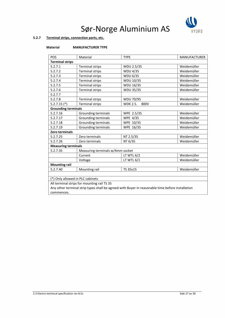
3.2.1.5 Placing and mounting of terminal strips
Terminal strips that are closer to the floor than 50 cm shall be mounted at an angle of 60°. Terminal
strips shall be numbered consecutively from left to right or from top to bottom. Terminals in
measurement loops shall be measuring terminals (see item 5.2.7.35). Measurement terminals shall be
equipped with sockets for 4 mm banana plugs.
Different voltage levels shall have their own terminal strips. This is also applicable for strange voltages
even where only one or two terminal strips are in question.
3.2.1.6 Cable Connections Control Power
Cable connections for control power shall be multistranded, with a minimum cross section of 0.75
mm². The conductors shall be placed in plastic conduits. The conductor ends shall have connection
sleeves at the connection point. The conductor ends shall be marked with marking sleeves that state
their respective component’s connection number, i.e., on relay/contactors: A1-A2, 13-14 etc. This
ensures easy replacement of components without having to use a diagram. Connection sleeves with
Sør-Norge Aluminium AS
2.3 Electro technical specification rev 8.5x Side 15 av 30
plastic tabs shall not be used as marking sleeves. For internal connections, there shall not be more than
two conductors in each connection point on components and one conductor in terminal strips.
3.2.1.7 Cable Conduits – Free Capacity
The plastic conduits shall not be filled more than 75% when the installation is ready for commissioning.
Whenever possible, the control power conductors shall be kept separate from the main power. A
plastic hose shall be used for the protection of connections between cabinet and cabinet doors (RITTAL
or similar).
3.2.1.8 Component Mounting and Marking
All components shall be mounted in such a manner that they can be readily replaced. They shall be
marked with position numbers in accordance with the drawings. Black letters on a white background
shall be used on signs/mark. The signs shall be mounted in the bottom of the cabinet, or special
marking bars, - not on the component or the plastic conduits. Contacts and relays can also be marked
with a ”light proof” marker on the marking signs from the factory. PLC I/O shall be marked on the front
with text.
3.2.1.9 Operation Signs Shall Have Norwegian Text
Operation signs shall have Norwegian text.
3.2.1.10 Operation Order
a) Increase, from bottom to top, or from left to right.
b) Reduce, counter clockwise from top to bottom, or from right to left.
c) Start/stop button: Location of start/stop buttons should preferably be vertical. Start button on top
and stop button at the bottom. If the start/stop buttons are placed horizontally, the start button
shall be placed on the right-hand side and the stop button on the left-hand side. For normal
operations, all switch levers shall be in vertical and middle positions, respectively.
3.2.1.11 Color Requirements for Indicator Lights and LEDs.
Signal Lights
RED - Alarm
GREEN - Ready for start
WHITE - Operation Light
Push Buttons
RED - Stop or Off
GREEN - Start or On
For others, in accordance with the current IEC-norm.
The Supply Voltage to signal lights/LED indicators shall be 24V.
For installations with more than 5 signal lights/LEDs, there shall be controls for lamp testing.
Incandescent lamps shall not be used.
3.2.1.12 Requirements for Conductor and Cable Colors
Neutral Conductor shall, in accordance with regulations, have a light blue color.
The Neutral Conductor shall always have the same insulation as the phase conductor. (Cu-shield shall
never be used as Neutral Conductor). N and PE shall only be connected (with a detachable connection
piece) in the first distribution.
The ground conductor shall be colored yellow/green in accordance with regulations. No other
connections shall be colored yellow or green.
PEN-conductors shall be colored yellow/green/blue.
In cabinets, black conductors shall be used for (L1, L2, and L3) outer conductors. Control power
conductors, 230V AC on the secondary side of the control power transformer shall be colored red. For
Sør-Norge Aluminium AS
2.3 Electro technical specification rev 8.5x Side 16 av 30
220V DC, the color violet shall be used (TP 90). 24V DC is performed with blue cable. For power
transformer loops, the cross section must be adapted to Buyer’s requirement for loop resistance.
Minimum cross section is 2.5 mm². Black conductors are used both for power and voltage transformer
loops.
Conductors with strange voltages and voltage from other installations shall be colored orange.
When using TP-conductors, reduced cross sections are not acceptable for what concerns conductivity
and temperature. PN and TP are regarded as being equal, and shall be mounted in accordance with
regulations as PN conductors. For machine installations, either 24V DC or 230V AC control power is
used. For 24V DC control power, the negative pole shall be connected to ground.
Voltage Level Cable Color Note
24V DC control power Blue
230V AC control power, insulated Red
220V DC Violet Control installations in 20kV
building
Power measurement Black Normally up to 5A
Voltage measurement Black Normally 100V
400V phase voltage Black
690V phase voltage Black
Strange voltage Orange Independent of voltage level
Neutral conductor Light Blue
3.2.1.13 IP Class Protection
All voltage-carrying parts must be protected against accidental touching, minimum IP 20.
Buyer shall agree on protection classes for surroundings and environment in case of doubt.
3.2.1.14 Cabinet Locks
In locked rooms with distribution boards, all cabinets shall be able to be opened or closed without
using keys or special tools. Outside of locked rooms with distribution boards, the cabinets shall be
opened using keys only.
3.2.1.15 Fuses
Automatic fuses are used up to and including 63 A (C-char). Automatic circuit breakers for important
control power circuits shall be equipped with signal contacts. For larger loads, load disconnectors or
power switches shall be used. Automatic circuit breakers or melting fuses shall not be used for 24V DC
supply to PLC inputs/outputs. See next section.
3.2.1.16 PLC Controls
All PLC controls shall have own Ethernet section for connection to PLC network, separated from
eventual I/ network.
Controls, including PLC, shall preferably be placed in separate cabinets with their own power supply,
etc. The PLC should be mounted on a carrier plate. 24V DC supply to PLC inputs/outputs shall be
guarded by an electronic over-current guard. Signals from over-current guards shall be connected to
alarm/indicator lights.
Sør-Norge Aluminium AS
2.3 Electro technical specification rev 8.5x Side 17 av 30
3.2.1.17 Lights in Cabinets
As a main rule, fluorescent lights with door switches shall be mounted in tall cabinets (2m or taller).
Other systems shall be agreed with Buyer. The installation in the cabinets shall be connected to special,
separate terminals, which are intended for 230V strange voltage.
3.2.1.18 Energy measurement
Energy measurement shall be delivered with machines. Shall be agreed with Buyer.
3.2.1.19 Fire detection
Buyer uses, among others, aspiration plants as fire detection. In connection with major deliveries of
cabinets, adapting for aspiration planta is of interest. Agreed with Buyer.
3.2.2 Installation and Mounting on Machines
3.2.2.1 Norwegian Regulations for Electrical Low Voltage Installations, including Instructions must be followed
when using NEK-400. (EN 60364)
3.2.2.2 Machines - Control
Electrical cabinets for machines shall be placed in a separate, electrical room. Input signals to PLCs
placed on the machine itself shall be connected to distributed I/O units on the machine.
ET200S/ET200SP on Profibus DP/Profinet and/or Asi bus shall be used as distributed I/O.
Motor starter equipment shall be placed in electrical cabinets in the electrical room and be controlled
from output cards on the PLC. 400V and 690V cables from motors and other power consumers shall be
routed directly to the contactor cabinet.
The control of solenoid valves for air and hydraulics shall be carried out with ET200S/ET200SP units in
cabinets next to the cabinets for solenoid valves. Exceptions from this may be allowed where there are
few valves and a short distance to the electrical cabinets. This must be agreed with the Officer in
charge.
The positioning of the machines shall be performed with laser. The laser shall be mounted on the fixed
part. When laser cannot be used, absolute sensors connected to Profibus DP shall be used.
3.2.2.3 Requirements for Safety System
All machines shall be manufactured in accordance with the Machine directive. Buyer shall approve SIL-
classification.
LOTO (Lock Out Tag Out) is a security system for removing all energy in machines and to prevent
accidental switch-on/startup of machines. All installations shall be arranged for such a system. Buyer’s
officer in charge shall be contacted for approval of the design.
3.2.2.4 Placement of Components
Each of the components that are part of the control system shall have a favorable position for
replacement, maintenance, and to avoid mechanical damage. Solenoid valves shall preferably be
mounted together in special cabinets, control voltage, preferably 24V DC, or as agreed upon.
Manufacturer, see item 5.2.6. Solenoid valves shall not be placed in the electrical cabinets. All
equipment must be mounted and protected against oil spills, water, snow and frost.
3.2.2.5 Marking of Components and Equipment
All equipment shall be clearly marked with position no. in accordance with the drawings. Engraved
signs with black letters on a white background shall be used. The signs shall not be placed on the
component, but on a mounting plate or construction part that is not being removed during normal
maintenance work.
Sør-Norge Aluminium AS
2.3 Electro technical specification rev 8.5x Side 18 av 30
3.2.2.6 Ventilation Installations
All controls are agreed upon (see item 5.2.9).
Electrical heating batteries shall be designed as convection heat batteries, not using radiation heat.
3.2.2.7 Soft Starters
Soft starters shall be used instead of star/triangle start. Soft starters shall be used for motor drive on
conveyors / chain belts. For installations where frequent motor start/stops because of energy
conservation is desired, soft starters shall be installed.
3.2.3 Cable Routing - General
3.2.3.1 Cable Trays
Cable trays of type WIBE, hot dipped or corresponding quality, shall be used. Outdoor- and in specific
areas indoors, stainless steel cable trays should be used. Otherwise must be agreed with Buyer.
Routing choices shall be agreed for each single case. When the installation is being commissioned,
there shall be 25% free room on the cable trays.
3.2.3.2 Cable Fastening - Strips
Outdoors, in pot-rooms and Foundry, acid proof steel strips shall be used for cable fastening. Plastic
strips made from UV proof material is otherwise accepted. This is also applicable for fastening of cable
marks.
3.2.3.3 Marking of Cables.
All cables shall be marked in both ends with their respective cable numbers in accordance with
drawings/cable lists.
3.2.3.4 Cable Dimensions.
It is Seller’s responsibility to choose correct cable dimensions according to load, short circuit
performance, elongation ratio, and voltage drops. Calculations of short-circuit and dimensioning shall
be documented in writing. Unless otherwise agreed upon, Febdok shall be used. Febdok database
files are to be delivered electronically with all files open for editing.
3.2.3.5 Capacity of Supply Cables.
Cables shall be delivered in accordance with item 5.2.2. Supply cables/power cables shall be
dimensioned for minimum 20% over-capacity. Different voltage levels shall normally not be present in
the same cable. Any deviations from this shall be agreed with Buyer’s electro department beforehand.
3.2.3.6 Cable Routing on Trays.
Power and signal cables on the same tray shall, when possible, be placed in separate paths.
3.2.3.7 Cable to Machines
For machines, cables of type PFSP or similar, shall normally be used.
Motor cables shall be of type PFSP or similar. This is a cable that is shielded and has an operation
voltage of 1kV.
Sør-Norge Aluminium AS
2.3 Electro technical specification rev 8.5x Side 19 av 30
4. REQUIREMENTS FOR DOCUMENTATION AND TRAINING
4.1 Drawings and Descriptions
All drawings and technical descriptions shall have Norwegian or English text. Operations and
maintenance instructions, etc. shall have Norwegian text.
Drawing basis and documentation, in addition to marking of installations and components shall be in
accordance with NEK 144. (EN 60617 / EN 61346)
Electrical components in machine installations shall be marked with a letter for the type of component
used and also be marked with a number for the side and power path where it can be found on the
electrical drawings.
4.2 For each installation the following documentation shall be delivered:
4.2.1 Installation Drawings
Can be prepared in standard formats A3 to A0. The drawings shall show the position of electric
components, equipment and cable connections in plants/buildings. The numbering and marking must
be consistent with the associated diagrams and drawing basis.
4.2.2 Arrangement Drawings
Can be prepared in format A4 to A1. The drawing(s) shall show internal construction, placement and
marking of equipment in distribution boards, consoles, etc.
4.2.3 One-Line Diagram
Can be delivered in the following formats; A4 and A3. The drawing shall represent one single one-line
diagram without control current. One-line diagrams for transformer stations (distribution stations)
shall be delivered, as well as for installations with voltages above 400V.
4.2.4 Current Flow Diagram
The following formats are accepted: A4 and A3. The drawings shall be divided into:
a) Main Current
b) Control Current
c) Alarm, error messages
d) Electrical schematics/hydraulic diagrams, i.e. hydraulic diagrams with electrical components
(solenoid valves, end switches, etc.) clearly marked with reference to electrical schematics.
e) Electrical schematics/pneumatic diagrams, similar to electrical schematics/hydraulic diagrams.
f) Diagrams for instruments, control and electronics.
g) Associated connection tables and terminal lists.
4.2.5 Drawings, etc., for PLC/Computer Controlled Plants
In addition to the mentioned current flow diagram, diagrams of inputs/outputs for PLC units and an
overview of used card types and outputs/inputs must be included. Furthermore, a program for the
concerned PLS-system is delivered. The PLC programs shall be developed on PC, program version in
accordance with agreement.
The program shall be transparent so that troubleshooting installations (processes) is made as simple as
possible. Both program structure and program must be documented in Norwegian or English.
After the installation is commissioned, Seller is responsible for providing Buyer with the copy latest
program version.
Sør-Norge Aluminium AS
2.3 Electro technical specification rev 8.5x Side 20 av 30
4.2.6 Apparatus List (parts list)
Format: A4
In the apparatus list, all the electrical and electrically controlled apparatuses in the installation shall be
included. The list shall include:
a) Quantity
b) Marking/Position
c) Manufacturer
d) Description, type, ordering data
e) Reference to current flow diagram
f) Notes with distributor/Seller
4.2.7 Cable List
Format: A4
In the list, all cables that are part of the group or installation in question shall be included. The cable
list shall include the following:
a) Connection from (denomination / reference) in accordance with IEC norm)
b) Connection to (denomination / reference) in accordance with IEC norm)
c) Number of conductors
d) Conductor cross section
e) Type
f) Length
g) Cable no.
h) Note
i) Voltage Level
4.2.8 Spare Parts
The offer shall include necessary spare parts and prices. In the general offer on spare parts for the
installation, electrical components shall also be included. These shall be listed with references as for
the parts list, item 4.2.6.
Any spare parts that are ordered in the main order shall be available when a plant is commissioned.
The spare parts list must include a complete type denomination and manufacturer.
Sør-Norge Aluminium AS
2.3 Electro technical specification rev 8.5x Side 21 av 30
4.2.9 Description.
For all plants, the following descriptions shall be included before commissioning:
a) Technical description of the installation’s function theory with reference to the electrical
documentation
b) Functional descriptions and technical documentation on the components used
c) Maintenance instructions for the same components shall be specified in a list with intervals.
d) The necessary documents for verification in accordance with NEK 400-6.
4.2.10 Drawing Copies.
2 sets of drawing copies shall be delivered to Buyer within a reasonable time frame before the
installation starts. 1 set with updated drawings shall be available to Buyer (at the plant) at all times,
from the start of installation until final documentation has been delivered.
4.2.11 Updated Drawings – AutoCad.
Seller of the installation shall deliver 2 sets of updated drawing copies with dates and signatures after
commissioning. The drawings and documents shall also be delivered electronically in the AUTOCAD
format (DWG format). Each sheet as one file. For drawing no. XXXXX sheet 1, the file name shall be
XXXXX-1.DWG.
4.2.12 Deadline for Delivery of Drawing Documentation
Unless otherwise agreed, the As Built-documentation shall be delivered to Buyer no later than one
month after plant commissioning.
4.2.13 Requirements for Storage of Drawing Copies
Copies of the original drawings, as built, shall be available from Seller for at least 10 years.
4.2.14 Professional Workmanship on Installations.
Buyer’s approval of presented drawings and documentations does not excuse Seller from the
responsibility to deliver a professionally executed installation, and to follow current regulations and
Buyer’s specifications.
4.2.15 Copying.
All copying expenses as mentioned in item 4.2.10 and 4.2.11 will be charged to Seller.
4.2.16 Assignment of Drawing and Object nos.
Seller shall contact Buyer to have Buyer’s drawing numbers and object numbers assigned. Both text
files and drawings shall be registered with Buyer’s drawing numbers. The drawing numbers and the
sheet numbers shall be unique.
4.3 Training
4.3.1 A training plan shall be prepared for operation and maintenance. The training plan from Seller shall be
in place before commissioning, testing, and start of operations for machine or installation. The training
plan shall be approved by Buyer and shall cover maintenance and operation.
Sør-Norge Aluminium AS
2.3 Electro technical specification rev 8.5x Side 22 av 30
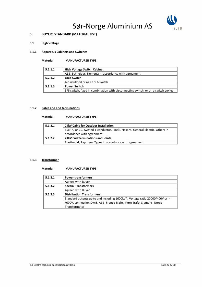
5. BUYERS STANDARD (MATERIAL LIST)
5.1 High Voltage
5.1.1 Apparatus Cabinets and Switches
Material MANUFACTURER TYPE
5.2.1.1 High Voltage Switch Cabinet
ABB, Schneider, Siemens; in accordance with agreement
5.2.1.2 Load Switch
Air insulated or as an SF6 switch
5.2.1.3 Power Switch
SF6 switch, fixed in combination with disconnecting switch, or on a switch trolley.
5.1.2 Cable and end terminations
Material MANUFACTURER TYPE
5.1.2.1 24kV Cable for Outdoor Installation
TSLF Al or Cu, twisted 1-conductor. Pirelli, Nexans, General Electric. Others in
accordance with agreement
5.1.2.2 24kV End Terminations and Joints
Elastimold, Raychem. Types in accordance with agreement
5.1.3 Transformer
Material MANUFACTURER TYPE
5.1.3.1 Power transformers
Agreed with Buyer
5.1.3.2 Special Transformers
Agreed with Buyer
5.1.3.3 Distribution Transformers
Standard outputs up to and including 1600kVA. Voltage ratio 20000/400V or -
/690V, connection Dyn5. ABB, France Trafo, Møre Trafo, Siemens, Norsk
Transformator
Sør-Norge Aluminium AS
2.3 Electro technical specification rev 8.5x Side 23 av 30
5.2 Low Voltage
5.2.1 Fuse Parts
Material MANUFACTURER TYPE
5.2.1.1 Load Disconnecting Switch
Load disconnecting switch 3NP Siemens AS
Load disconnecting switch SLP, XLP ABB
5.2.1.2 Load Switch
Load switch 3KL50-3KL61 Siemens AS
5.2.1.3 High Power Cartridges
High power cartridges 3ND, 3NA Siemens AS
5.2.1.4 Power switch and engine protection switches
Power switch 3 VF, 3 RV, 3WN Siemens AS
5.2.1.10 Automatic circuit breakers AC, Residual current circuit breaker 5SU
Automatic circuit breakers for AC 5SY (440V AC) Siemens AS
B and C Characteristic.
5.2.1.11 Automatic fuses DC
Automatic circuit breakers for DC S 280UC (220V=) ABB Stotz
5.2.1.12 Electronic protection for 24V DC PLC inputs/outputs.
Siemens Sitop diagnosis module, part no. 6EP1961-2BA00
1.2.2 Cable
Material MANUFACTURER TYPE
In compliance with Officer in Charge, non-halogenated cables shall be used in some areas.