35
SEMINAR ON “TESTING AND CERTIFICATION OF GREEN CONSTRUCTION MATERIALS” Sound Insulation for Glass and Panel Ir Dr CHONG Fan

SEMINAR ON “TESTING AND CERTIFICATION OF GREEN CONSTRUCTION MATERIALS”
Sound Insulation for Glass and Panel
Ir Dr CHONG Fan

HIGHLIGHTS
1. Sound insulation of building construction
2. Sound insulation tests
3. Prediction models for sound insulation
4. Improvement of sound insulation

SOUND INSULATION OF BUILDING CONSTRUCTION
What is sound insulation of building construction?
It is a measure of the ratio of the sound energy striking the building component relative to the energy which is transmitted through the building component.
Sound insulation / sound transmission loss (TL) is expressed in decibels as follows,
TL = 10 log( W1 / W2)
TL of a building component varies with frequency, usually increasing as the frequency increases

SOUND INSULATION OF BUILDING CONSTRUCTION
Important to know the Sound Insulation Performance of Building elements
To compare different constructions
To calculate acoustic privacy between rooms
To calculate noise levels from outdoor sources, such as road traffic
To engineer optimum solutions to noise control problems

SOUND INSULATION OF BUILDING CONSTRUCTION
Single-number rating of airborne sound insulation
Sound Transmission Class (STC)- ASTM E90
Weighted sound reduction index (Rw)- BS EN ISO 140-3
Rw and STC ratings are determined by laboratory test of a specimen.
The higher the Rw or STC rating, the better the sound insulation provided by a partition.

SOUND INSULATION TESTS
Two adjacent reverberation rooms are arranged with an opening between them in which the test specimen is installed
Omni-Power Sound Source
Test partitionMicrophone
Source Room Receiving Room

SOUND INSULATION TESTS
Care is taken that the only significant sound transmission path between rooms is by way of the test specimen.
An approximately diffuse sound field is produced in both rooms.
Acoustic reflectors were Acoustic reflectors were installed in the reverberation installed in the reverberation chamberschambers

SOUND INSULATION TESTS
Sound incident on the test specimen causes it to vibrate and create a sound field in the second room, the receiving room.
The space- and time-averaged sound pressure levels in the two rooms are determined. In addition, with the test specimen in place, the sound absorption in the receiving room is determined.

SOUND INSULATION TESTS
Testing Procedure
Background Measurement

SOUND INSULATION TESTS
Testing Procedure
Transmission Loss Measurement

SOUND INSULATION TESTS
Testing Procedure
Reverberation Time Measurement

SOUND INSULATION TESTS
The sound pressure levels in the two rooms, the sound absorption in the receiving room and the area of the specimen are used to calculate sound transmission loss as shown in the following equation.
For ASTM E90 and BS EN ISO 140-3:
Because transmission loss is a function of frequency, measurements are made in a series of frequency bands.
)/log(1021 ASLLTL +−=

SOUND INSULATION TESTS

SOUND INSULATION TESTS
10
20
30
40
50
6010
012
516
020
025
031
540
050
063
080
010
0012
5016
0020
0025
0031
5040
0050
00
Frequency, f, Hz
Sou
nd re
duct
ion
inde
x, R
, dB
Sound reduction index, R (1/3 oct)Weighted sound reduction index Rw is 47dB
Test Result
Rw Standard Curve
STC Standard Curve

SOUND INSULATION TESTS
Transom (Vertical room to room)

SOUND INSULATION TESTS
Transom (Vertical room to room)
SOUND INSULATION TESTS
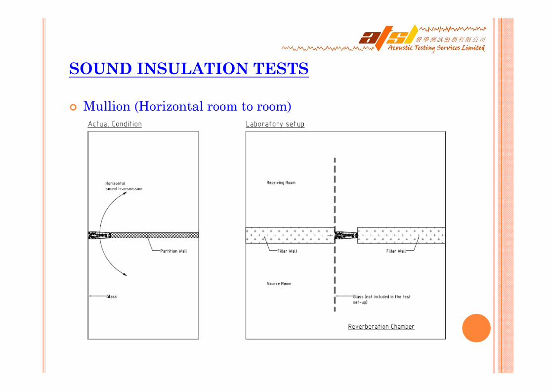
Mullion (Horizontal room to room)

SOUND INSULATION TESTS
Mullion (Horizontal room to room)

PREDICTION MODELS FOR SOUND INSULATION
Needs for Sound Insulation Prediction
Laboratory measurements have been made for many different types of partitions. However, it is impractical to test every possible design
To investigate the effects of changes to existing designs
It is necessary to have reliable methods It is necessary to have reliable methods for predicting the sound transmission for predicting the sound transmission loss of typical building constructions.loss of typical building constructions.

PREDICTION MODELS FOR SOUND INSULATION
Homogeneous Panels
The most important property is the mass per unit area of the panel. The mass law gives a very simple prediction of the transmission loss TL
However, for most practical building materials the static stiffness must be sufficiently high that coincidence between airborne and structure borne waves will occur within the frequency range of interest (50 – 5,000 Hz).
The mass law is modified to include the change in transmission at the critical frequency and above
47log20 −= (mf)TL
47)/2log(10)log(20 −−= cmfTL πωηω

PREDICTION MODELS FOR SOUND INSULATION
Homogeneous Panels
For most thin homogeneous materials used in building construction, above equation provides an excellent prediction of the transmission loss over most of the frequency range.
However, one additional effect must be taken into account to obtain good accuracy at low frequencies. For typical test construction of 10 – 12 m2, the radiation efficiency of forced waves must be taken into account for frequencies of less than 200Hz. Sewell gives the correction to the infinite area panel as
])(1log[20)]log[ln(10 221
ckATL ωω−+−=Δ

PREDICTION MODELS FOR SOUND INSULATION
Double Panels
Many walls and floors are constructed of thin linings with an air space between, and these can, if correctly designed, give high sound transmission loss.
For a partition consisting of two thin homogeneous panels, separated by an air gap containing an acoustically absorbing blanket, and with no interconnections between the two panels. Sharp has developed expressions for the transmission loss in 3 frequency ranges as follows:
121
1021
021
629)log(20
47)](log[20
ffTLTLTLffffdTLTLTL
ffmmfTL
>++=<<−++=
<−+=
L
L
L

PREDICTION MODELS FOR SOUND INSULATION
Double Panels
These expressions do not contain any parameters to describe the variation in performance due to different acoustic absorbers in the airspace and it is a practical problem of some interest to determine this effect. Fahy gives an alternative high frequency solution.
121 )/log(206.8 ffkdTLTLTL >+++= Lβα

PREDICTION MODELS FOR SOUND INSULATION
Double Panels
• While some constructions can approach the ideal of double panels without interconnections, in practice most construction will have some type of solid or resilient connection between the panels. Sharp has developed relatively simple expressions for the transmission loss of double panels with either point or line interconnections.
18)]/(log[20)log(2045)]/(log[20)log(20
21121
21121
−++∗+=−++∗+=
+
+
mmmfbTLTLmmmfeTLTL
c
c

INSUL SOUND INSULATION PREDICTION

INSUL SOUND INSULATION PREDICTION

INSUL SOUND INSULATION PREDICTION

INSUL SOUND INSULATION PREDICTION

INSUL SOUND INSULATION PREDICTION

INSUL SOUND INSULATION PREDICTION

INSUL SOUND INSULATION PREDICTION

TO ACHIEVE HIGH SOUND INSULATION
Increase thickness of single panes (to increase mass).
Use laminated glass to reduce the coincidence effect. Laminated glass can achieve STC rating 3 or more higher than monolithic glass of identical thickness.
Use double-glass construction with at least 1/2-in-wide spacing between panes of different thickness (so panes will have different resonant frequencies). Ratio of thicknesses should be about 2:1. Replacing one pane of glass with equal thickness of laminated glass increases STC by 4.

TO ACHIEVE HIGH SOUND INSULATION
Increase spacing between panes up to 6 in. TL increases by about 3 dB per doubling of mean separation distance.
Avoid using lightweight frames, and where especially high TL is required, use separate frames to reduce flanking of sound energy.
Line interior perimeter of frame with sound-absorbing treatment (to improve TL by 2 to 5 dB at high frequencies).
Mount panes with soft neoprene edge gaskets, which provide higher TL than putty or caulking for the same thickness of glazing.

CONCLUSION
Any prediction tools are not a substitute for actual test/measurement,
• Extensive comparisons with test data indicate that INSUL can reliably predict Rw / STC values to within 3dB for most constructions.
• In practical, some building constructions are too complicated topredict.
However, the sound insulation performance can be predicted with acceptable engineering accuracy over the frequency range 50-5,000 Hz using simple and readily available expressions.

END OF PRESENTATION
Thank You!
Q & A


