INSTRUCTION MANUAL GR1562 SOUND-LEVEL CALIBRATOR Form 1562-0100-J Apr il 1978 Thi s in st rum e nt is capable of ca libr ating sound· le ve l meters used for measurements required under Part 1910 .95 "Occupat ion al Noise Exposure," (D ept. of L abor) of the Co de of Federal Regula - tions, Ch ap. XV II of Titl e 29 (36 F. R. 7006). This instrument carries U.S. Bureau of Mines, Mining Enforcement Safety Administration approval for use in methane-air mi x ture only. Approval Number 2G-2263. Copyright 1 967 by General Radio Company Co n cord, Massach u se tt s, USA
Transcript
INSTRUCTION MANUAL
GR1562
SOUND-LEVEL CALIBRATOR
Form 1562-0100-J
Apr i l 1978
Thi s instrum ent is capable of ca librating sound· leve l meters used for measurements required under Part 1910.95 "Occupat i o n al Noise Exposure," ( Dept. of L abor) of the Code of Federal Regula tions, Ch ap. XV II of Titl e 29 (36 F. R . 7006).
This instrument carries U.S. Bureau of Mines, Mining Enforcement Safety Administration approval for use in methane-air mi xture only. Approval Number 2G-2263.
Copyright 1967 by General Radio Company
Co ncord, Massach usett s, USA
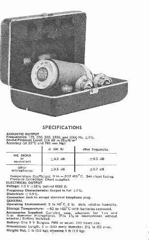
SPEC! FICATIONS
at 500 Hz other frequencies
WE 640AA o r
equiva lent
other microphones
± 0.3 dB
± 0.5 dB
Temperature Coefficient: 0 to -.012 dBf°C. Pressu re Correction: Chart supplied.
Connector: Jack to accept standard telephone plug. GENERAL Operating Environment: O to 40° C, O to 95% relative humidity. Storage Temperature: - 40 to +60°C with batteries removed. Accessories Supplied: Carrying case. adapto rs fo r 1-in and Y.-i n diameter microphones. {Fits 1 Ifs-in microphones without adaptor.) Battery included. Battery: One 9 V Burgess PM6 or equal. 120 hours use. Dimensions: Length, 5 in (130 mm); diameter, 2'h i n (55 mm). Weight: Net, 1 lb (0.5 kg); s~lpplng 4 lb (1 .9 kg).
~ ... a; :l .... < I
f i '2 ~
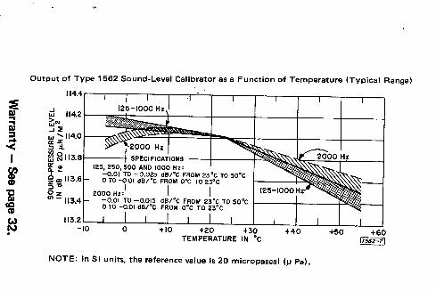
Output of Type 1562 Sound-Level Calibrator as a Function of Temperature (Typical Range)
~~ ~2113.8~---+ a: ., 125, 250, 500 AND 1000 Hz: ~ ~ -0.01 TO -0.025 dB/°C FROM 23°C TO 50°C z m 113.6 0 T0-0.01 dBl°C FROM o•c TO 23°C
S; 2000 Hz:1 I I ui -113.4 0~g1_6~~~~~~ ~~6:i ~!lc°~o2~;~zo so•c
113.2~~-~-~-~-~-~-~-~-~-~-~-~-~--' -10 0 +10 +20 +30 +40 TEMPERATURE IN °C
NOTE: In SI units, the reference value Is 20 micropascal (µPal.
+50 +60 11562·7]
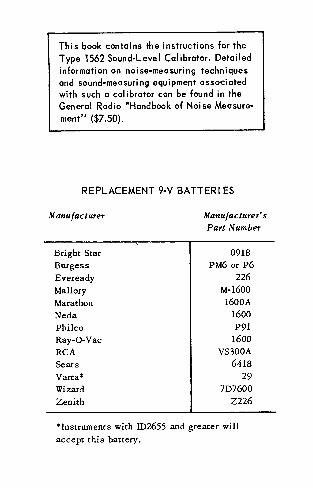
This book contains the instructions for the Type 1562 Sound-Level Calibrator. Detailed information on noise-measuring techniques and sound-measuring equipment associated with such a calibrator can be found in the General Radio •Handbook of Noise Measurement" ($7.50).
REPLACEMENT 9-V BATTER I ES
Manufacturer Manufacturer's
Part Number
Bright Star 0918 Burgess PM6 or P6 Eveready 226 Mallory M-1600
a. Turn the dial counter-clockwise and hold one second. b. Observe that bulb lights, indicating good battery. c. Turn the dial clockwise to the desired frequency.
SELECTION OF ADAPTOR:
a. If microphone is 1 1/8-inch diameter, use
instrument in the present configuration. b. If microphone is 1 -inch or Yi-inch di ammeter, se I ect the proper adaptor.
TO CALIBRATE A SOUND-LEVEL METER:
a. Place calibrator slowly over the microphone.
b. Read the output on the Sound-Level Meter associated with the microphone. See appro· priate table in text. c. Adjust the instrument under test to read
correctly or note error and apply correction to reading.
TO TURN INSTRUMENT OFF:
a. Turn the dial counter-clockwise to OFF.
NOTE Batteries shipped uninstalled. See para. 2.1.1.
Section I
INTRODUCTION
1.1 PURPOSE.
The Type 1562 Sound-Level Calibrator is a convenient and accurate self-contained device for checking the calibration of sound measuring instruments. Its intended use is for the field calibration of instruments that use as their input transducer the Type 1560-P5 or -P6 Piezoelectric Ceramic Microphones. These instruments include the Type 1551 and 1565 Sound-Level Meters, the Types 1558-A and 1558-BP Octave Band Noise Analyzers, plus the Type 1564 Sound and Vibration Ana -lyzer, and the Type 1525 Data Recorder. Many other microphone-instrument systems can be calibrated if the microphones used are the Type 1560-P5 or -P6, the Type 1560-P3 or -P4, the Type 1551-PlL or -PIH, or the Western Electric 640-AA Laboratory Standard Microphone, or its equivalent.
1.2 DESCRIPTION .
1.2.l GENERAL.
Figure 1-1 shows the Type 1562 with its adaptors, and Table 1-1 documents the type and function of the control and acces -sories.
I
4
Figure l· l. Type 1562 Sound· Level Calibrator. ~----------Tobie 1-1----------~
2
Fig. J.J Ref.
Controls and Accessories
Name 1·ype Pu11c 1ion
OFF -ST ART- ? -pos i tion Turns instrument on. FREQUENCY selector Checks battery.
switch Selects frequency.
Knurled nut Tubula r Holds shield on in -strument.
Electrical Phone jack Provides l volt ±203 Output sinewave output at
each frequency.
Microphone (P/N 1562- Adapts i.ns t rument to Adaptor 6 130) 1/2 inch d iameter
microphone.
Microphone (P/N 1562- Adapts instrument to Adaptor 6100) 1 inch diameter
microphone.
Battery 9 V Burgess Power for ins trument . PM6 or eq-uivalent
Case Holds instrument and accessories .
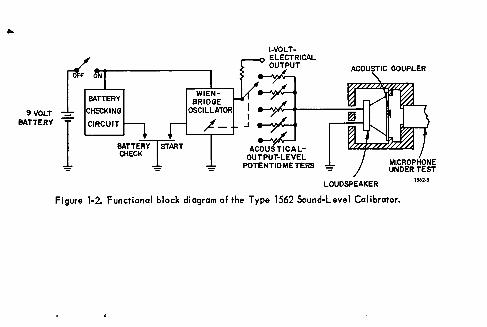
As shown in the block diagram of Figure 1-2, the instrument consists of an oscil -lator which drives a loudspeaker to generate high-level acoustic calibrating signals in a coupler that fits over the measurement microphone. Figure 1-3 shows the coupling end of the instrument. Various diameter microphones will probably be involved at times, and Figures 1-4, 1-5, and 1-6 are provided to show mounting position of typical microphones.
1.2.2 THE OSCILLATOR.
The oscillator is a battery-operated Wien -bridge transistor oscillator that gen -erates five ANSI -preferred frequencies, 125, 250, 500, 1000, and 2000 Hz. The oscillator operates from a 9-volt battery and is very stable, has low distortion, and low noise.
1.2.3 ACOUSTIC OUTPUT.
The oscillator drives a small control -led-reluctance magnetic loudspeaker. The loudspeaker drives one end of a small acoustic coupler. The other end of the coupler is closed by the microphone to be calibrated. A controlled leak to atmosphere in the wall of the coupler is adjusted so that constant voltage across the loudspeaker terminals generates essentially constant sound-pressure level in the coupler from below 100 Hz to 1000 Hz. Above 1000 Hz the response
3
....
9VOLT BATTERY
BATTERY ISTART CHECK
WIENBRIDGE
OSCILLATOR
,L-
LOUDSPEAKER
Figure 1-2. Functional block diagram of the Type 1562 Sound-Level Calibrator.
1562°5
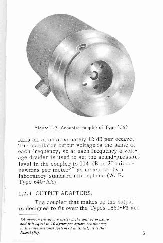
Figure 1- 3. Acoustic coupler of Type 1562
falls off at approximately 12 dB per octave . Tl1e oscillator output voltage is the same at each frequency, so at each frequency a voltage divider is used to set the sound- pressure level in the coupler to 114 dB re 20 micron ewtons per meter2* as measured by a laborator y standard microphone (W. E. Type 640-AA).
1.2 .4 OUTPUT ADAPTORS.
The coupler that makes up the output is designed to fit over the Types 1560-P3 and
''''A newton per square merer is til e unit of pressure and it is equal to J 0 dynes per square cenrimete~ in th e intemational system of units (SI}, iris the Pascal (Pa). 5
CONTROLLED LEAK TO ATMOSPHERE
TYPE 1562
LOUDSPEAKER
COUPLING CAVITY
1s.s2.1
Figure 1-4. Calibration mounting position of GR Types 1560-Pl, -P3, ar -P4 microphones.
-P4 (1 1/8-inch diameter) microphones. These microphones were used for many years on sound-level meters and other sound-measuring equipment. There is still a large number in use throughout the industry. They also have the largest outside diameter of any widely used measurement microphone. Newly designed or special-measurement microphones are generally smaller in diameter, and it is usually much easier to design adaptors to reduce the diameter of the coupler fitting than it is to effect an increase in its diameter.
The most common smaller diameter microphones are the Types 1560-P5 and -P6 Piezoelectric Ceramic Sound-Level Meter Microphones currently supplied on General Radio sound-measuring instruments. The diameter of these microphones is 15/16 inch.
6
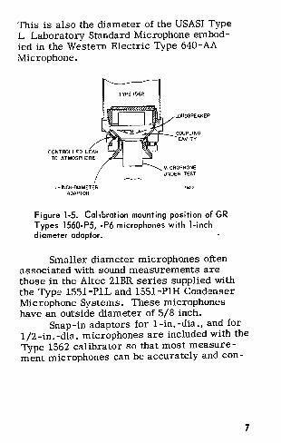
This is also the diameter of the USASI Type L Laboratory Standard Microphone embodied in the Western Electric Type 640-AA Microphone.
CONTROLL!:.:D LEAK TO ATMOSPHERE
I - INCH-DIAMETER ADAPTOR
TYPE 1562
LOUDSPEAKER
COUPLING CAVITY
Figure 1-5. Calibration mounting position of GR Types 1560-P5, -P6 microphones with 1-inch diameter adaptor.
Smaller diameter microphones often associated with sound measurements are those in the Altec 21BR series supplied with the Type 1551-PlL and 1551-PlH Condenser Microphone Systems. These microphones have an outside diameter of 5/8 inch.
Snap-in adaptors for 1-in. -dia., and for 1/2-in. -dia. microphones are included with the Type 1562 calibrator so that most measurement microphones can be accurately and con-
7
I
CONTROLLED LEAK TO ATMOSPHERE
2 - INCH DIAMETER ADAPTOR
TYPE 1562
LOUDSPEAKER
COUPLING CAVITY
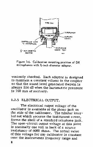
Figure 1-6. Calibration mounting position of GR microphones with Yi-inch diameter adaptor.
veniently checked. Each adaptor is designed to maintain a constant volume in the coupler so that the sound level generated therein is always 114 dB when the barometric pressure is 760 mm of mercury.
1.2.5 ELECTRICAL OUTPUT.
The electrical output voltage of the oscillator is available at the phone jack on the side of the calibrator. The tubular knurled nut which secures the instrument cover, forms the shell of a standard telephone jack. The open -circuit output voltage at this point is nominally one volt in back of a source resistance of 6000 ohms. 'The actual value of this voltage for any calibrator is constant over the instruments frequency range and 8
independent of normal environment con -ditions and battery voltages. The generated output is a sinewave with less than o.s3 distortion.
The tolerances on the characteristics of the thermistor (Rl33 ), which determines the operating level of the oscillator, permit operating levels among oscillators to differ by ±203. Each oscillator will operate, however, at the constant level dictated by its thermistor.
1.2.6 BATTERY CHECKING CIRCUIT.
The operation of the calibrator oscilla -tor is independent of the battery voltage as long as it remains at 6 volts or higher, The battery-checking circuit is included in the instrument so the operator can quickly determine if his battery is safely in the operating range. When the calibrator dial is turned to the spring return, counter-clockwise position, the lamp (PlOl) will light only if the battery voltage is 6 volts or higher. If the battery is below 6 volts the transistor switch remains open and the lamp will not light. Since the lamp load is much higher than the normal oscillator load on the battery, the battery must also be in good condition or its voltage will drop below the lamp ignition level during the battery check of one or two seconds, because of the excess load.
9
1.2. 7 CONTROLS AND CONNECTORS.
MASTER CONTROL
The master control is the plastic com -bination knob, dial, and nameplate at the top of the instrument. This control is used to turn the instrument on, check the battery condition, and select the operating frequency. A red background area illuminates the transparent engraving to indicate the dial setting.
ACOUSTIC-OUTPUT COUPLING
The acoustic output from the calibrator is obtained at the bottom of the instrument, at the opposite end from the main controL The correct acoustic output is obtained when a 1 1/8-inch-diameter microphone, or smaller diameter microphone in a 1 1/8-inch-diameter adaptor is properly seated in the 1 1/8-inchdiameter recess at the bottom of the cali -brator.
10
Section 2
OPERATING PROCEDURE
2.1 PRELIMINARY CHECKS.
2.1.1 BATTERY CHECK.
Install the battery in the instrument by
removing the cover (paragraph 4-3) and connecting the battery between the battery clips.
Replace the cover. With the instrument upright on a desk
or bench and the output phone jack connector
facing the operator, the master control should
be in the position shown in Figure 2-1. That
11
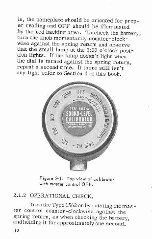
is, the nameplate should be oriented for proper reading and OFF should be illuminated by the red backing area. To check the battery, turn the knob momentarily counter - clockwise against the spring return and observe that the small l:imp at the 3 :00 o'clock pos i -tion lights . If the lamp doesn't light when the dial is turned against the spring return, repeat a second time. If there still isn't any light refer to Section 4 of this book.
Figure 2-1. Top view of calibrator with master control OFF .
2.1.2 OPERATIONAL CHECK.
Turn the Type 1562 on by rotating the mas -ter control counter -clockwise against the spring return, as when checking the battery, and holding it for approximately one second. 12
Turn the knob clockwise to the 2000-Hz position. A clear 2000-Hz tone should be easily audible. If a more raucous tone is heard it will be necessary to hold the knob in the START position a little longer before setting it to 2000 Hz. One second or so is usually long enough at normal room temperatures; however, at low temperatures the knob must be held in the start position somewhat longer to ensure proper starting of the oscillator.
When the clear 2000-Hz tone is heard, the calibrator is ready for use and can be set to any of its five frequencies without repeating the starting procedure.
2.2 CALIBRATION OF SOUND-MEASURING INSTRUMENTS.
The Type 1562 Sound-Level Calibrator is adjusted to develop a constant sound-pressure level of 114 dB re 20 micronewtons per meter2 at each of five frequencies (125, 250, 500, 1000, and 2000 Hz}, when its acoustic coupler is placed over a high (acoustic} im -pedance sound-measuring microphone. This level is established by adjusting the calibra -tor output to register a 114-dB sound-pressure level on a sound-measuring system using a carefully maintained laboratory standard microphone, such as the Western Electric 640-AA, with a pressure calibration determined by reciprocity and traceable to the National Bureau of Standards. This calibra -tion is performed at a temperature of 23 ° C and an atmospheric pressure of 760 mm of Hg. Normal variation of temperature and
13
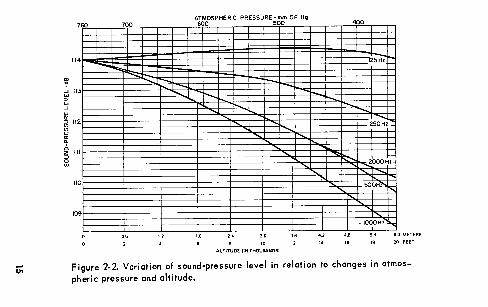
atmospheric pressure will have negligible effect on the sound-pressure level developed. The specifications give the value of the temperature coefficient, and the curves in Figure 2-2 show the variation of sound-pressure level with atmospheric pressure,
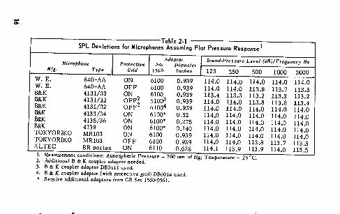
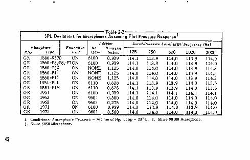
So long as the volume enclosed by the coupler is kept constant, including the effective volume of the microphone to be calibra -ted, the sound-pressure level developed in the calibrator coupler is constant at 114 dB. The adaptors supplied with this calibrator are designed so that most of the commonly used measurement microphones are calibra -ted at the 114 dB sound-pressure level. Tables 2-1 and 2-2 list commonly used sound-measuring microphones. The appropriate calibrator adaptor, microphone adaptor if required, and the sound-pressure levels developed by the calibrator for each microphone are also tabulated. The levels listed in Tables 2-1 and 2-2 are sound-pressure levels and are the levels that would be indi -cated by a measuring system using a microphone with a flat pressure response, plus amplifiers and meters with flat frequency characteristics. Many sound-measuring systems (i.e., sound-level meters, see paragraph 2.3.1) are designed to have other than flat pressure response, so that the levels given in Tables 2-1 and 2-2 must be adjusted to account for the desired response of the measuring system. The procedure for cali -brating sound-level meters will be explained in the following paragraphs. 14
u;
~ d II
~ ...J
~
7flJ
'
~ 112
~ ~II " ~
110
109
700 ·--
- -
AJottOSPHERIC PRESSURE 500 OF Hg
..... ~
' ..... ....... .... .......
' ..... '
I
" AL TITUOE UN THOUSANDS!
-'
400 --
'
'
25H?r::
250~..._
2000Hz -~
500H"''<;
" IOOOHz,,,,,.,
6.0 METERS
20 FEET
Figure 2·2. Variation of sound-pressure level in relation to changes in atmos
I I Adapto' I Sound-P,.ssu'" Level (dB)/frequency Hz Microphone Protective No. Diameter Mfg. Type Grid 1562· Inches I 125 250 500 1000 2000
W. E. 640-AA ON 6100 0.939 114.0 114.0 114.0 W. E. 640-AA OFF 6100 0.939 114.0 114.0 113.8 B&K 4131/32 ON 6100 0.939 113.4 113.3 113.2 B&K 4131/32 OFF2 61003 0.939 114.0 114.0 113.8 B&K 4131/32 OFF2 61004 0.939 114.0 114.0 114.0 B&K 4133/34 ON 6100* 0,52 114.0 114.0 114.0 B&K 4135/36 ON 6100* 0.275 114.0 114.0 114.0 B&K 4138 ON 6100* 0.140 114.0 114.0 114.0 TOKYORIKO MR103 ON 6100 0.939 114.0 114.0 114.0 TOKYORIKO MR103 OFF 6100 0.939 114.0 114.0 113.8 ALTEC BR series ON 6110 0.628 114.1 113.9 113,9
1. Measurement conditions: Atmospheric Pressure - 760 mm of Hg; Temperature - 23 °C. 2. Additional B & K coupler adaptor needed. 3. B & K coupler adaptor DBOlll used. 4. B & K coupler adaptor (with protective grid) DB0014 used. • Require additional adaptors from GR Set 1560-9561.
Sound-level -meter microphones man -ufactured in the United States are usually adjusted to have nominally flat response to sounds of random incidence in a free-field. The response of the amplifier in the soundlevel meter is modified to obtain the required weighting characteristics. To determine what a sound-level meter should read when the Type 1562 is coupled to its microphone, one must correct for the difference between the microphone random -incidence, free-field response and its pressure response, and for the difference between a flat-amplifier response and the weightedamplifier response.
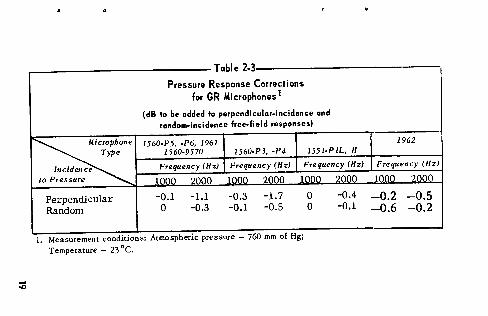
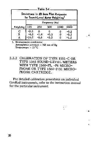
Microphone-calibration response curves supplied by General Radio Company are for the free-field, random -incidence response. The Type 1559-B Reciprocity Microphone Calibrator also yields the free-field random incirlence response of the microphone. Corrections of perpendicular-incidence and random -inci -dence responses to the pressure responses of General Radio microphones are given in Table 2-3. ANSI weighting characteristics for sound-level meters from the USA Standard Specification for Sound-Level Meters, Sl.4, 1971, are listed in Table 2-4 for the five calibrator frequencies.
18
..
::0
Table 2-3
Pressure ~ :orrect ions
for G onesl
(dB to be added le ular-incidence and
random-incide old responses)
~· 1560-P5, 0 P6, 1961
1560-9570 1560·P3, ·P4 1551-P IL, H
e
e
Frequency (Hz) Frequency (Hz) Frequency (Hz)
e 10nn 2000 10on 2000 lonn ?nnn
Perpendicular -0.1 -1.l -0.3 -1.7 0 -0.4
Random 0 -0.3 -0.l -0.5 0 -0.1
1. Measurement conditions: Atmospheric pressure - 760 mm of Hg;
Temperature - 23 °C.
1962
Frequency (Hz)
in no ·>nno
-0.2 -0.5 -0.6 -0.2
0 e . T bl 2 4
Deviations in dB from Flot Response for Sound-Level Meter Weighting 1
Frequency (Hz)
Weighting 125 250 500
c -0.2 0 0 B -4.3 -1.4 -0.3 A -16.2 -8.6 -3.3
1. Measurement conditions: Atmospheric pressure - 760 mm of Hg Temperature - 23 °C
1000
0 0 0
2000
-0.2 -0.2 +1.2
2.3.2 CALIBRATION OF TYPE 1551-C OR TYPE 1565 SOUND-LEVEL METERS WITH TYPE 1560-P5, -P6 MICROPHONE OR TYPE 1560-2131 MICROPHONE CARTRIDGE.
For detailed calibration procedures on individual GenRad instruments, refer to the instruction manual for the particular instrument.
20
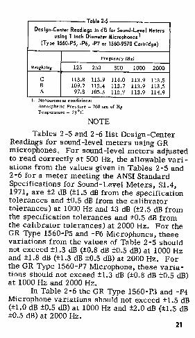
a e T bl 2 5 Design-Center Readings in dB for Sound-Level Meters
using 1 inch Diameter Microphones 1 (Type 1560-P5, -P6, -P7 or 1560-9570 Cartridge)
Frequency (Hz)
Weigh/ing 125 250 500
c 113-8 113.9 114.0 B 109.7 112.4 113.7 A 97.8 105.3 110.7
I. Measurement condtt10ns: Atmospheric Pressure - 760 mm of Hg Temperature - 23 °C
NOTE
1000
113.9 113.9 113.9
2000
113.5 113.5 114.9
Tables 2-5 and 2-6 list Design-Center Readings for sound-level meters using GR microphones. For sound-level meters adjusted to read correctly at 500 Hz, the allowable variations from the values given in Tables 2-5 and 2-6 for a meter meeting the ANSI Standard Specifications for Sound-Level Meters, Sl .4, 1971, are ±2 dB (±1.5 dB from the specification tolerances and ±0.5 dB from the calibrator tolerances) at 1000 Hz and ±3 dB (±2.5 dB from the specification tolerances and ±0.5 dB from the calibrator tolerances) at 2000 Hz. For the GR Type 1560-P5 and -P6 Microphones, these variations from the values of Table 2-5 should not exceed ±1.3 dB (±0.8 dB ±0.5 dB) at 1000 Hz and ±1.8 dB (±1.3 dB ±0.5 dB) at 2000 Hz. For the GR Type 1560-P7 Microphone, these variations should not exceed ±1.3 dB (±0.8 dB ±0.5 dB) at 1000 Hz and 2000 Hz.
In Table 2-6 the GR Type 1560-P3 and -P4 Microphone variations should not exceed ±1.5 dB (±1.0 dB ±0.5 dB) at 1000 Hz and ±2.0 dB (±1.5 dB ±0.5 dB) at 2000 Hz.
21
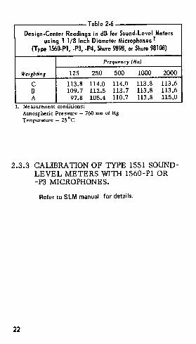
a e T bl 2 6
Design-Center Readings in dB for Sound-Level Meters using 1 1/8 Inch Diameter Microphones l
(Type 1560..Pl, -Pl, -P4, Shure 9898, or Shure 98108)
Frequency (Hz)
Weighting 125 250 500 1000 2000
c 113.8 114.0 114.0 113.8 113.6 B 109.7 112.5 113.7 113.8 113.6 A 97.8 105.4 110.7 113.8 115.0
1. Measurement cond1uons:
Atmospheric Pressure - 760 mm of Hg Temperature - 23 °C
2.3.3 CALIBRATION OF TYPE 1551 SOUNDLEVEL METERS Willi 1560-Pl OR -P3 MICROPHONES.
Refer to SLM manual for details.
22
2.3.4 CALIBRATION CHECKS ON TYPE 1563.
Refer to SLM manual for details.
2.3.5 CONDENSER MICROPHONE SETS.
A special set of adaptors (P/N 1560-9561) is available as an accessory to permit calibra -tion of five combination microphone/preamplifier sets utilizing small diameter condenser microphones. They are sets P/N 1560~9532 through -9536, ranging in size from 1/2 to 1/8 inch. The adaptors nest into one another to get down to the smaller sizes and ultimately mate with calibrator through the ! -inch adaptor, P /N 1562-6100. Operation is otherwise the same as for ceramic microphones.
CAUTION
Don't confuse the slight resistance of an internal 0-ring in the smaller adaptors for true bottoming.
2.4 ALTITUDE AND PRESSURE CORRECTIONS.
The Type 1562 is subject to altitude and atmospheric pressure changes in relation to its acoustical output. A graph has been plotted (Figure 2-2) to show the change in soundpressure level with a change in altitude and
23
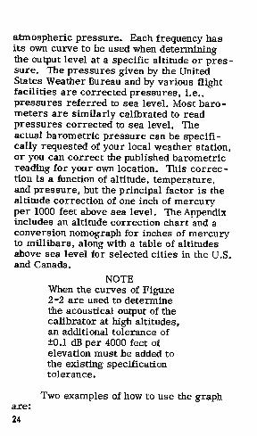
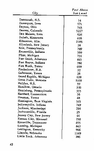
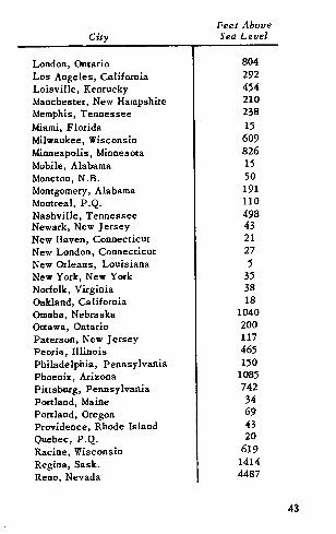
atmospheric pressure. Each frequency has its own curve to be used when determining the output level at a specific altitude or pressure. The pressures given by the United States Weather Bureau and by various flight facilities are corrected pressures, i.e., pressures referred to sea level. Most barometers are similarly calibrated to read pressures corrected to sea level. The actual barometric pressure can be specifically requested of your local weather station, or you can correct the published barometric reading for your own location. This correction is a function of altitude, temperature, and pressure, but the principal factor is the altitude correction of one inch of mercury per 1000 feet above sea level. The Appendix includes an altitude correction chart and a conversion nomograph for inches of mercury to millibars, along with a table of altitudes above sea level for selected cities in the U.S. and Canada.
are: 24
NOTE When the curves of Figure 2-2 are used to determine the acoustical output of the calibrator at high altitudes, an additional tolerance of ±0.1 dB per 4000 feet of elevation must be added to the existing specification tolerance.
Two examples of how to use the graph
a. Conditions of measurement: Frequency, 250 Hz Altitude, 8000 feet Microphone, Western Electric
640-AA Solution by graph: Instrument tolerance from specification, ±0.5 dB Graph sound-pressure level and tolerance,
113.5 ±0.2 dB Final acoustical output, 113.5 ±0. 7 dB
b. Conditions of measurement: Frequency, 500 Hz Altitude, 18000 feet Microphone, Western Electric
640-AA Solution by graph: Instrument tolerance from specification, ±0.3 dB Graph sound-pressure level and tolerance,
110.2 ±0.45 dB Final acoustical output, 110.2 ±0. 75 dB
This final acoustical output is the value of sound-pressure level that will be generated by the calibrator under the stated measurement conditions.
25
Section 3
PRINCIPLES OF OPERATION
3.1 THE WIEN-BRIDGE OSCILLATOR.
3.1.l GENERAL.
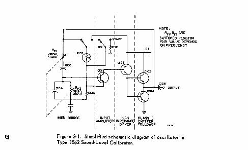
The Wien-bridge circuit (Figure 3-1) used in this oscillator performs two functions. Two of the bridge arms (ClOS, Rp1 and Cl04, Rp2) form a frequency determining impedance divider which provides positive feedback to sustain oscillation. The remaining two arms (Rl33 and RIOS}, form a resistive divider which provides negative feedback to stabilize the amplitude.1
1. For a detailed discussion of chis design fearure,
see Fulks, R.G., "Novel Feedback Loop Stabilizes
Audio Oscillacorn, Electronics, Vol. 36 No. 5
February, 1963. Available as General Radio reprint
A-107.
26
!::!
( I I I I I I I
RFI
<m~~
/
/ /
/
I /
V WIEN BRIDGE
RIOBI
I I I
lstART
Rl32
~
: INPUT I HIGH I I AMPLIFIER I IMPEDANCE! I : DRIVER I
a+
CLASS B EMITTER FOLLOWER
NOTE: RFI' RF2 ARE
SWITCHED RESISTOR PAIR. VALUE DEPENDS ON FREQUENCY
CI06 (-o OUTPUT
·~"
figure 3-1. Simplified schematic diagram of oscillator in Type 1562 Sound·Level Calibrator.
3.1.2 FREQUENCY AND STABILITY.
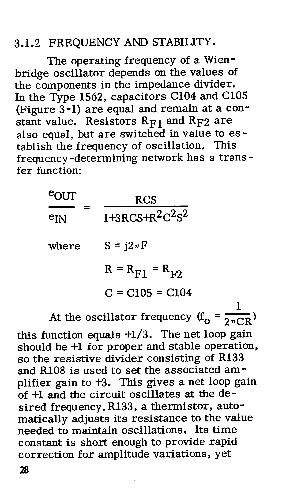
The operating frequency of a Wienbridge oscillator depends on the values of the components in the impedance divider. In the Type 1562, capacitors Cl04 and ClOS (Figure 3-1) are equal and remain at a constant value. Resistors Rp1 and Rp2 are also equal, but are switched in value to establish the frequency of oscillation. This frequency-determining network has a trans -fer function:
where
RCS
S = j211F
R = RFl = RF2
C = ClOS = Cl04 1
At the oscillator frequency (f0 = 2,,CR)
this function equals +1/3. The net loop gain should be +l for proper and stable operation, so the resistive divider consisting of Rl33 and Rl08 is used to set the associated am -plifier gain to +3. This gives a net loop gain of +l and the circuit oscillates at the desired frequency. Rl33, a thermistor, automatically adjusts its resistance to the value needed to maintain oscillations. Its time constant is short enough to provide rapid correction for amplitude variations, yet
28
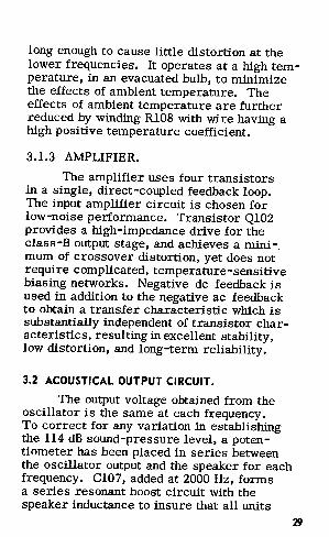
long enough to cause little distortion at the lower frequencies. It operates at a high temperature, in an evacuated bulb, to minimize the effects of ambient temperature. The effects of ambient temperature are further reduced by winding RIOS with wire having a high positive temperature coefficient.
3.1.3 AMPLIFIER.
The amplifier uses four transistors in a single, direct-coupled feedback loop. The input amplifier circuit is chosen for low-noise performance. Transistor Ql02 provides a high-impedance drive for the class-B output stage, and achieves a mini-. mum of crossover distortion, yet does not require complicated, temperature-sensitive biasing networks. Negative de feedback is used in addition to the negative ac feedback to obtain a transfer characteristic which is substantially independent of transistor characteristics, resulting in excellent stability, low distortion, and long-term reliability.
3.2 ACOUSTICAL OUTPUT CIRCUIT.
The output voltage obtained from the oscillator is the same at each frequency. To correct for any variation in establishing the 114 dB sound-pressure level, a potentiometer has been placed in series between the oscillator output and the speaker for each frequency. Cl07, added at 2000 Hz, forms a series resonant boost circuit with the speaker inductance to insure that all units
29
will develop the required 114 dB soWldpressure level. This is necessary because the output of the transducer used falls off in response above 1000 Hz.
3.3 ELECTRICAL OUTPUT CIRCUIT.
The oscillator output voltage is also fed to a telephone jack through a resistive divider network (Rl29, Rl30, R131, Figure 4-5) which makes available a sinewave of 1 V, rms, ±203, with a source impedance of 6000 n.
3.4 BATTERY CHECK CIRCUIT.
The battery checking circuit (Figure 4-5) is a transistor switch. The two transistors, Q106 and Q105, are in the ON state when the battery is above 6 volts. When this condition exists the bulb, PlOl, will light if the master control is held in the ST ART -BATTERY CHECK position.
CAUTION Do not hold the switch in the
START-CHECK BATTERY position any longer than nee• essary because the battery wi 11 run down very fast.
If the battery voltage drops below 6 volts, the emitter and base voltages of Q106 drop, causing a change in the collector voltage. This change is in the upward direction which will raise the base voltage of Q105,
30
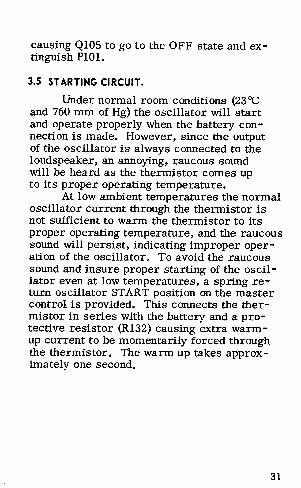
causing Ql05 to go to the OFF state and extinguish PlOl.
3.5 STARTING CIRCUIT.
Under normal room conditions (23 °C and 760 mm of Hg) the oscillator will start and operate properly when the battery con -nection is made. However, since the output of the oscillator is always connected to the loudspeaker, an annoying, raucous sound will be heard as the thermistor comes up to its proper operating temperature.
At low ambient temperatures the normal oscillator current through the thermistor is not sufficient to warm the thermistor to its proper operating temperature, and the raucous sound will persist, indicating improper operation of the oscillator. To avoid the raucous sound and insure proper starting of the oscil -lator even at low temperatures, a spring return oscillator START position on the master control is provided. This connects the thermistor in series with the battery and a protective resistor (Rl32) causing extra warmup current to be momentarily forced through the thermistor. The warm up takes approx -imately one second.
31
Section 4
SERVICE AND MAINTENANCE
4. 1 WARRANTY.
32
~GenRad WARRANTY
W11 warrant that thb product is frve from defects in material and workmanship and, when properly used, will perform in ac:cordenco with applicable GenRad 1peclflcation1.
It within one year after original shipment ii Is found not to meet thb standard, it will be repaired or, at tho option of GanRed, nrploc:ed at no charge whan returned to a
GanRad Mr.ice facility. Changes in the product not appro'ed by GenRad Iha!) void this warranty. GenRad shllll not be liabht for any indirect. spedal, or consequential dam8£181, oven if notice has been giHn of the possibility of auch damages.
THIS WARRANTY IS IN LIEU OF ALL OTHER WARRANTIES, EXPRESSED OR IMPLIED, INCLUDING, BUT NOT LIMITED TO, ANY IMPLIED WARRANTY OF MERCHANTABILITY OR FITNESS FOR A PARTICULAR PURPOSE.
GenRad policy 11 to maintain product repair C!lpabHlty for a period of ten yaan after
1Jrlglnal shipment iind to make this capability avuilllbla at th11 thin prsvalllng sc:hsdula
of chargo1.
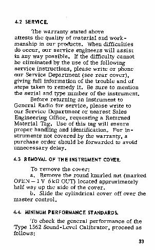
4.2 SERVICE.
The warranty stated above attests the quality of material and workmanship in our products. When difficulties do occur, our service engineers will assist in any way possible, If the difficulty cannot be eliminated by the use of the following service instructions, please write or phone our Service Department (see rear cover), giving full information of the trouble and of steps taken to remedy it. Be sure to mention the serial and type number of the instrument.
Before returning an instrument to General Radio for service, please write to our Service Department or nearest Sales Engineering Office, requesting a Returned Material Tag, Use of this tag will ensure proper handling and identification, For instruments not covered by the warranty, a purchase order should be forwarded to avoid unnecessary delay.
4.3 REMOVAL OF THE INSTRUMENT COVER.
To remove the cover: a, Remove the round knurled nut (marked
OPEN - 1 V 6 kQ OUT) located approximately half way up the side of the cover.
b. Slide the cylindrical cover off over the master control.
4.4. MINIMUM PERFORMANCE STANDARDS.
To check the general performance of the Type 1562 Sound-Level Calibrator, proceed as follows:
33
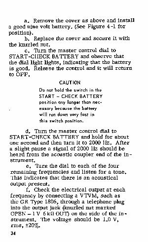
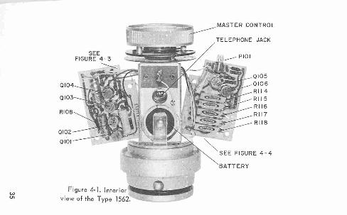
a. Remove the cover as above and install a good nine volt battery. (See Figure 4-1 for position).
b. Replace the cover and secure it with the knurled nut.
c. Turn the master control dial to START-CHECK BATTERY and observe that the dial light lights, indicating that the battery is good. Release the control and it will return to OFF.
CAUTION
Do not hold the switch in the
START - CHECK BATTERY position any longer than nec
essary because the battery wi 11 run down very fast in this switch position.
d. Turn the master control dial to START-CHECK BATTERY and hold for about one second and then turn it to 2000 Hz. After a slight pause a signal of 2000 Hz should be heard from the acoustic coupler end of the in -strument.
e. Turn the dial to each of the four remaining frequencies and listen for a tone. This indicates that there is an acoustical output present.
f. Check the electrical output at each frequency by connecting a V1VM, such as tlle GR Type 1806, through a telephone plug into the output jack (knurled nut marked OPEN - 1 V 6 krl OUT) on the side of the instrument. The voltage should be 1.0 V, rms, ±203.
34
w Vl
0 1 02~ 0 10 1
"'z , r "' F igure 4- 1. In ter ior
view of the Type 1562. --
JACK
BATTE RY
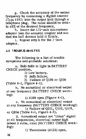
g. Check the accuracy of the output frequency by connecting a digital counter (Type 1192) into the output jack through a telephone plug. The value should be within ±3 % of the desired frequency.
h. Insert the 1/2-inch microphone adaptor into the acoustic coupler and see that the ball detents hold it firmly.
i. Repeat step h for the !-inch adaptor.
4.5 TROUBLE·ANALYSIS.
The following is a list of trouble symptoms and probable solutions:
a. Bulb fails to light in BATTERY CHECK position.
1) Low battery. 2) Bulb failure. 3) Failure of QlOS or Q106
(Table 4-1, Figure 4-1). b. No acoustical or electrical output
at any frequency (BATTERY CHECK working):
1) RIOS open (Figure 4-1). c. No acoustical or electrical output
at any frequency (BATTERY CHECK working): 1) Failure of QlOl, Q102, Q103,
or Q104 (Table 4-1, Figure 4-1). d. Acoustical output not "clean" signal
at all frequencies, electrical output high (about 3 volts, rms) (BATTERY CHECK working):
1) Thermistor (R133) open.
36
ALTITUDES ABOVE SEA LEVEL FOR SELECTED CITIES IN U.S. AND CANADA
City
Akron, Ohio Albany, New York Allentown, Pennsylvania Ashland, Kentucky Atlanta, Georgia Augusta, Georgia Baltimore, Mary land Bangor, Maine Bay City, Michigan Binghamton, New York Birmingham, Alabama Boise, Idaho Boston, Massachusetts
Brandon, Man. Buffalo, New York Burlington, Vermont Bridgeport, Connecticut Calgary, Alta. Cambridge, Massachusetts Camden, New Jersey Campbellton, N.B. Charleston, South Carolina Charlotte, North Carolina Charlottetown, P .E .I. Chicago, Illinois Cleve land, Ohio Colorado Springs, Colorado Columbus, Georgia Columbus, Ohio Council Bluffs, Iowa Dallas, Texas
Feet Above "Sea Level
950 20 320 530 ll05 141 81 21 593 865 598
2717 45
1204 590 190 12
3439 80 30 4! 13 734
8 604 600
6012 261 759 989 437
41
42
City
Dartmouth, N.S. Davenport, Iowa Dayton, Ohio Denver, Colorado Des Moines, Iowa Duluth, Minnesota Edmonton, Alta. Elizabeth, New Jersey Erie, Pennsylvania Evansville, Indiana Flint, Michigan Fort Smith, Arkansas Fort Wayne, Indiana Fort Worth, Texas Fredericton, N.B. Galveston, Texas Grand Rapids, Michigan Great Falls, Montana Halifax, N.S. Hamilton, Ontario Harrisburg, Pennsylvania Hartford, Connecticut Houston, Texas Huntingtnn, West Virginia Indianapolis, Indiana Jackson, Mississippi Jacksonville, Florida Jersey City, New Jersey Kansas City, Missouri Knoxville, Tennessee Lansing, Michigan Lexington, Kentucky Lincoln, Nebraska Little Rock, Arkansas
London, Ontario Los Angeles, California Loisville, Kentucky Manchester, New Hampshire Memphis, Tennessee Miami, Florida Milwaukee, Wisconsin Minneapolis, Minnesota Mobile, Alabama Moncton, N.B. Montgomery, Alabama Montreal, P.Q. Nashville, Tennessee Newark, New Jersey New Haven, Connecticut New London, Connecticut New Orleans, Louisiana New York, New York Norfolk, Virginia Oakland, California Omaha, Nebraska Ottawa, Ontario Paterson, New Jersey Peoria, Illinois Philadelphia, Pennsylvania Phoenix, Arizona Pittsburg, Pennsylvania Portland, Maine Portland, Oregon Providence, Rhode Island Quebec, P.Q. Racine, Wisconsin Regina, Sask. Reno, Nevada
Richmond, Virginia Rochester, New York Saint John, N.B. Saint Louis, Missouri Saint Paul, Minnesota Sale Lake City, Utah Sacramento, California San Antonio, Texas San Francisco, California Saskatoon, Sask. Savanah, Georgia Scranton, Pennsylvania Seattle, Washington Shceveporc, Louisiana Sioux Falls, South Dakota South Bend, Indiana Spokane, Washington Springfield, Massachusetts Sydney, N.S. Syracuse, New York Tacoma, Washington Toledo, Ohio Toronto, Ontario Topeka, Kansas Tuscon, Arizona Tulsa, Oklahoma Utica, New York Vancouver, B.C. Washington, D.C. Wichita, Kansas Windsor, Ontario Winnipeg , Man. Youngstown, Ohio
Feet Above "Sea Level
84 509 21
460 754
4300 30
657 50
1596 42
757 51
217 1405 718
1905 101 10
410 87
594 250 909
2382 700 448 18 100 1285 580 727 832
APPENDIX
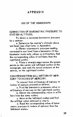
USE OF THE NOMOGRAPH
CORRECTION OF BAROMETRIC PRESSURE TO
STATION ALTITUDE.
To obtain a corrected barometric pressure
for a station: a. Determine the station's altitude above
sea level (see chart later in Appendix). b. Obtain a barometric pressure reading
corrected ta sea level from a barometer. (If the
barometer reads only values in millimeters, find
the corresponding value of millibars from the
right-hand scales. c. Place a straight-edge across the proper
points on the center and left-hand scales of the
nomograph, and read the actual pressure at the
station, on the right-hand scales.
CONVERSION FROM MILLIMETERS OF MER
CURY TO INCHES OF MERCURY.
To convert from millimeters of mercury to inches of mercury proceed as fol lows:
a. Find the barometric pressures value in
millimeters of mercury on the right-hand scales. b. Obtain the corresponding value in milli·
bars from the same scales. c. Move to the left-hand scales and find
the millibar value obtained in step b. d. Read the corresponding value of baro
metric pressure in inches of mercury from the
left-hand scales.
39
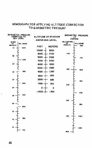
NOMOGRAPH FOR APPL YING ALTITUDE CORRECTION TO BAROMETRIC PRESSURF
BAROMETER PRESSURE ALTITUDE OF STATION
BAROMETRIC PRESSURE CORRECTED TO AT SEA LEVEL
ABOVE SEA LEVEL STATION
INCHES MILLIMETERS OF MILLIBARS OF MILLIBARS
MERCURY MERCURY 700 FEET METERS 31 1000
10000 3000
9000 2700 •50 30
8000 2400 100 1000 7000 2100
29 6000 1800
5000 1500 600 800
28 950 4000 1200
3000 900
27 2000 600 850
900 1000 300 650
26 0 0
-1000 ---100 900
25 850
700
24 950 800
23
IOOO
22 750
21 1050 700
800
40
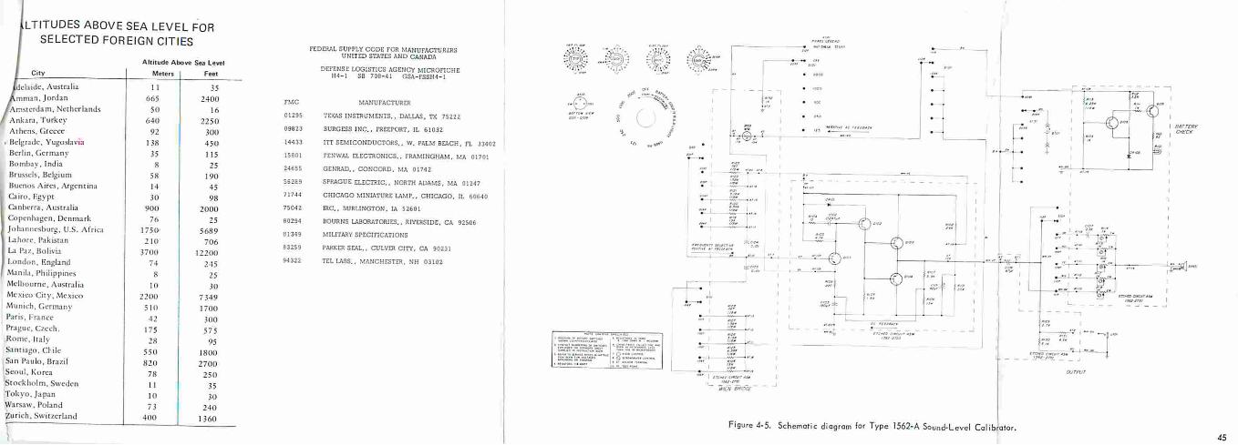
L T ITUDES ABOVE SEA LEVEL FOR SELECTED FOREIGN CITIES
rt:Dt:RAI. SUPPLY CODr. rOR MANUrACTUR£RS UNITtD STATES AND CANADA
f igure 4-5. Schcmoric diagram for Type 1562-A Sound-Level Col ibratcr. 45
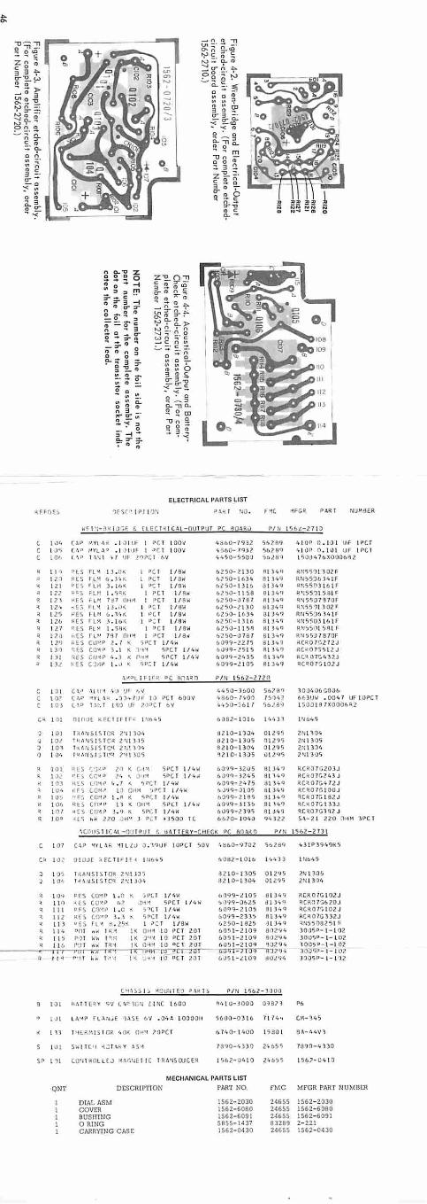
ELECTRICAL PARTS LIST
~FFOE~ 1fS(' I Pl 10'1 P !\lot I ·10. F "'
•FGR PART NUlldER
Wf 1 '!- :'\M: j ,,,.j,f. t [ LEt l ~ l(Al-OUl PUT P& ~QARu PI N 156t-27 1J
1\)1, (A P t'.YL •\ K .. l J I llf I PC I lOOV 1fabo-1<nz 56289 4 10• O. l OI UF 1rcr I J' (1\I' t..tVL A'' • I JIUF I ·' C I l OOV '•8 60-7q)2 507 89 41 1 \) Jl 0 .. 101 UF l PC I l Cf• ( \P 1 \~I 't 7 +J fo .!'lPC J l•V t, 4 S 0 -5500 56l8Q l 5 004 76X0006fl2
• l l ' " LS fl'< l l . O< I • C I l/ SW 6250-2 130 -R I ) t, q R>!S5')110 2F ~ 1 21 •cs I l" b . Y• h 1 PC 1 l/ aw 67.50-1 6 34 8 1349 Rtt>5'.lbl4 1F
121 •rs • LI-I ) . l b~ 1 PC t I/SW •l50- l ll6 8 1 )4 9 Q~550)16 l F
• 12 ? ::c.s ;.lM 1 . 5•~ I PC I l/Sw bl)U-1l58 Bl )4Q • ' :551 1581 f R 12 1 •FS rl~ 7 :t7 llt1M I PCT l / 8W 6250-0 787 ft ! 3 4 q ~N 5507970F
• 1 l.1• -<~S f L" l :S . 1H I 11 ;: ' I /OW bl50-l l3 0 HI 3 1, C) QN55'll302 • ~ I 2 'j '-' F\ ~LM (. . 1't i<. 1
" ' t l /8W t..2~0- l t.34 Ll l. 3 109 RN55!ll> v. 1r
12u RC S r u~ J .. 1 bi<. l u.: t l /Bw t. 2 50- 1 ) lb Bl Jt, 9 l<N 5503 16 l F
" 127 ia.s l='l ~ I . 5H <. 1 •C t l / 8W bZS0- 11 5~ 8 1 }<.'1 RN5 50151\l ,..: q 1 ? 1} I\[~ IU•' HI 0 11\i l ·' Cf 118' '•250-\l 78 7 Bl ) t.q k~ 55Jl870F R i n •ES cuvn z . I 5Ptr l/t.W 6 0 9 9-ZZ IS 8 1J 11 C1 ~c~o rr.21 ZJ ~ I) I ~F:S CO"" S . I ,., .. ~P(.T l /4 '.ol 6\1~9- lS I 5 Al v. q Rt"0 7~51 2 J
R l J I qc.'S tUiP 4 . 3 I( flrt~ 5 PC! 1/4< •0??-2• 35 8 l )4q llt~OlGt.3 1.J
131. H~ CJ,IP I . J < 'iP: r l /41< 60?9-l l 05 8 134? QC~07G LOZJ
\ ~DL1 f 1 rR ti( nn .1~n PIN 156 Z- 27l0
D l C \1' \\ U o\ '•;.> VF •• v 44';0-JUOO S 678'l l 0D4 06 G006 t 07 c .1r "'.'fl j, o( .,.,_.. I }F I J rc 1 bOOV '• 8 (., 0 - 11.01 / S'l't ! o63UW • 004 7 UF I OPCl 103 l ,. l ·' ~· 1 I ~~ Uf l lPC r b'I t. ·,:,.o-'5 b t r '.i6J8'l l 5uJ l 8 7XOOOh ~Z
c~ l 11 n 1r1:.>t KELT If 1r .. l '!b4 ~ bJ82- 10 1b I lo4)1 1'16 45
') 10 1 T 'l A~ St S T Ct: 2'-1 11 0 1. 6Z I O- l)J4 0 12?5 2Ul ;01, IOl T ~h~S I S T CR Z ~ I J 15 UZ I 0- 1 305 Oll? '.i ZN l 305
") 10 1 l t< hN S. I S TC~ 2 N~ l )4 8 2 10- 130'• Ol l.9'i 2N \ ) ".)(, ') I Qt. f ~ M~!i- 1 .i l P ~ 7'1 1 lO'i ~2 1 0-1)()5 l>\205 21\l l )0')
10 1 RtS (ti ·~ tJ Z·' ~ r: t "\ 5 PC T l/4 W 60~9-JZ05 81 J4 ~ RC~07 GZ03J
l J, '' f ) c:;c-.o ? 4 "' .1•1'-4 lljP (. l l /t.,.' {),)qq-1 z:,5 d l "l'~ q RC~ 07GZ4 3J
" ! !'11 RLS Lfl-.1l 4 . 7 < srr. ! 11 '-'" b~??-24 7 5 Bl 14Q RC~07G 4 7ZJ l 1ur. I FS c.a~·v l.l cm-t '1P~ l l/ 4W ~ll~9- J I 05 at )r, q ~no IGIOOJ
I Ut; •ts:;. ((J'' rl I·" K r;tiC I l / 1or+ 60?9-2 195 3 1 )4 Q ~CR07G I 82 J ll l 06 •ts (O"'lfl 11 !( 011~ SPCI l /4'iol bQC,Q-j l J~ Bl v ,q QC~07G l 3 ) J ~ I 0 I "cs (IJ l.t ') j . CJ I( 5PC T l /4W 6 09 9-2)q5 8 1 y , q QC~0 7GJqz J q I O• " L~ hW 21>0 DH'.\ J P(:T • 3500 TC 6&10- 101. 0 <JI· l2 2 Sh-2 l 7.20 OH M JPC l
\COIJS l IC•L- OUI Pu r ~ U~ TIERY-Cft ~CK PC 80 l .t0 PI N 1562-2731
l 07 C•W 'tYLA i::. 'ill lU J . 1'>Uf I OPC T 50V '• Hb0- 970 2 sozaq 431P 39491<~
c• 10.: U I J JI ;., EC. T ! F 1 c: < l Ub.:. 5 6 082-l 0 16 1114) 3 ltlb45
J 1 O:> T1lA NS I S TOlot l'l t J\l ~ 32 10- 1305 0 12 '15 ZN I 305 J 1 o• l ~ 'INS ! S T C~ 2.~ 1 j , )4 ttz I 0-1304 ~ l l?~ 2N L31Jt1
R l lN ~F.S co~~ t.0 < 1Vt. T l/ 4W b099-ll05 6 1 J 4'f HCR0 7G I OZJ l l ~ •ES CO"'° <>7 ..!~i~ SPCI L/tt\ol •1 ~)9q-Ob25 d i j4q RCIH>1~&20J
q Il l OFS (.QY,~ t . o i(, ,,C. 1 l/t.W 60"19-2 105 91 J4Q l\CR07t; 102 J q 1 12 !lf> CO''P l. 1 . sr•cr l /4W 6 0 119- 23) 5 8 1. J4'J RCQ0 7G332J < 1 1 3 0 ES rt' a. zs< I ,,: T I / SW 6250- 1825 tJ L J4q ~N551l82 5 l F q l 14 DnJ "" t ~• l< 0• 4'1 10 •e r 20 1 60~ 1 -2 1 09 80294 ) OOSD- l - 10 2
1 15 M l w:.i. ,.,,.. I~ J' 'M 10 •C T ZO T 605 1-2 109 902"14 )OOS•- 1- 10 2 11 6 f•!.J j Wh r~ • I~ n~·< 10 °c l 7U1 1>05 1- 2 10 ? qozq,, 1005P-l - I 0 2
~~rH-f11""'JCT<O-r-~'!ftt'07.'I'• JOO'iP- 1- 102 n I I i r.,1 f ~. ,,,.: I '< .... , .... 10 l'C T 2~1 6 U5 1-ll09 d0l'l4 JOO~J>- l-1 ~z
C\i \ ~ -> I .> "1 01.J:'il f 9 ~..\~ T ~ P/N I SbZ-1:100
B I OI ''"T T E~Y ~ I/ L ,r '\ON l I NC 1600 "'• l 0- JOOO 0~071 P6
1 J I Ltir-otr rl ANvE 1l.\SE ov . Ot1A 1000011 r;(I00-03 1 b 71 14 .. (M.-3't 5
l 1J T•H • .RH IS I GR '• IJ~ OH'-' 10PCl 6 7 1, 0- 1 '·00 1580 1 61'4- r, 4y3