January 23, 2014 David Martin and Members of the Siting Council Connecticut Siting Council Ten Franklin Square New Britain, CT 06051 RE: Notice of Exempt Modification 151 Sand Hill Road South Windsor, CT 06074 N 41° 33’ 09.53” W -72° 33’ 07.17” Sprint Site #: NV2.5_CT33XC555 Dear Mr. Martin and Members of the Siting Council: On behalf of Sprint, SBA Communications is submitting an exempt modification application to the Connecticut Siting council for modification of existing equipment at a tower facility located at 151 Sand Hill Road, South Windsor, CT. The 151 Sand Hill Road facility consists of a 187’ Monopole Tower owned and operated by SBA Properties, LLC. In order to accommodate technological changes and enhance system performance in the State of Connecticut, Sprint plans to modify the equipment configurations at many of its existing cell sites. Please accept this letter and attachments as notification, pursuant to R.C.S.A. Section 16- 50j-73, of construction which constitutes an exempt modification pursuant to R.C.S.A. Section 16-50j- 72(b)(2). In compliance with R.C.S.A. Section 16-50j-73, a copy of this letter and attachments is being sent to the chief elected official of the municipality in which the affected cell site is located. As part of Sprint’s modernization project, Sprint desires to upgrade their equipment to meet the new standards of 4G technology. The new equipment will allow customers to download files and browse the internet at a high rate of speed while also allowing their phones to be compatible with the latest 4G technology. Attached is a summary of the planned modifications, including power density calculations reflecting the change in Sprint’s operations at the site along with the required fee of $625. The changes to the facility do not constitute modifications as defined in Connecticut General Statutes (“C.G.S.”) Section 16-50i(d) because the general physical characteristics of the facility will not be
Transcript
January 23, 2014
David Martin and Members of the Siting Council Connecticut Siting Council Ten Franklin Square New Britain, CT 06051
RE: Notice of Exempt Modification 151 Sand Hill Road South Windsor, CT 06074 N 41° 33’ 09.53” W -72° 33’ 07.17” Sprint Site #: NV2.5_CT33XC555
Dear Mr. Martin and Members of the Siting Council:
On behalf of Sprint, SBA Communications is submitting an exempt modification application to the Connecticut Siting council for modification of existing equipment at a tower facility located at 151 Sand Hill Road, South Windsor, CT.
The 151 Sand Hill Road facility consists of a 187’ Monopole Tower owned and operated by SBA Properties, LLC. In order to accommodate technological changes and enhance system performance in the State of Connecticut, Sprint plans to modify the equipment configurations at many of its existing cell sites. Please accept this letter and attachments as notification, pursuant to R.C.S.A. Section 16-50j-73, of construction which constitutes an exempt modification pursuant to R.C.S.A. Section 16-50j-72(b)(2). In compliance with R.C.S.A. Section 16-50j-73, a copy of this letter and attachments is being sent to the chief elected official of the municipality in which the affected cell site is located.
As part of Sprint’s modernization project, Sprint desires to upgrade their equipment to meet the new standards of 4G technology. The new equipment will allow customers to download files and browse the internet at a high rate of speed while also allowing their phones to be compatible with the latest 4G technology.
Attached is a summary of the planned modifications, including power density calculations reflecting the change in Sprint’s operations at the site along with the required fee of $625.
The changes to the facility do not constitute modifications as defined in Connecticut General Statutes (“C.G.S.”) Section 16-50i(d) because the general physical characteristics of the facility will not be
significantly changed or altered. Rather, the planned changes to the facility fall squarely within those activities explicitly provided for in R.C.S.A. Section 16-50j-72(b)(2). 1. The overall height of the structure will be unaffected. 2. The proposed changes will not extend the site boundaries. There will be no effect on the site compound other than the new equipment cabinets. 3. The proposed changes will not increase the noise level at the existing facility by six decibels or more. 4. The changes in radio frequency power density will not increase the calculated “worst case” power density for the combined operations at the site to a level at or above the applicable standard for uncontrolled environments as calculated for a mixed frequency site. For the foregoing reasons, SBA Communications on behalf of Sprint, respectfully submits that he proposed changes at the referenced site constitute exempt modifications under R.C.S.A. Section 16-50j-72(b)(2). Please feel free to call me at (508) 251-0720 x 302 with any questions you may have concerning this matter. Thank you, Kri Pelletier SBA Communications Corporation 33 Boston Post Road West Suite 320 Marlborough, MA 01752 508-251-0720 x 302 + T 508-251-1755 + F 203-446-7700 + C [email protected]
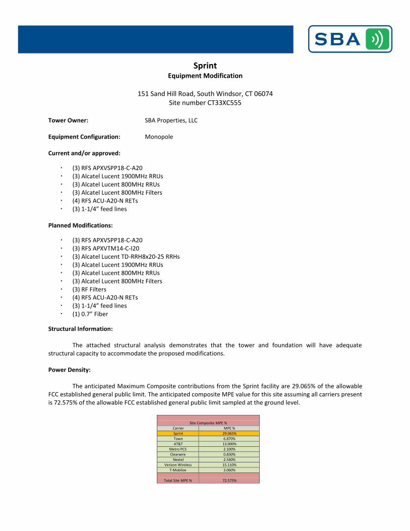
The attached structural analysis demonstrates that the tower and foundation will have adequate structural capacity to accommodate the proposed modifications.
Power Density:
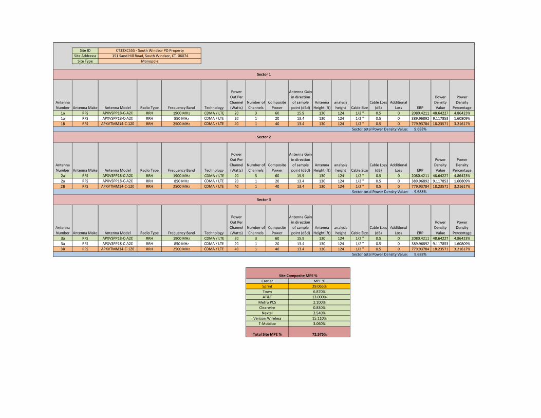
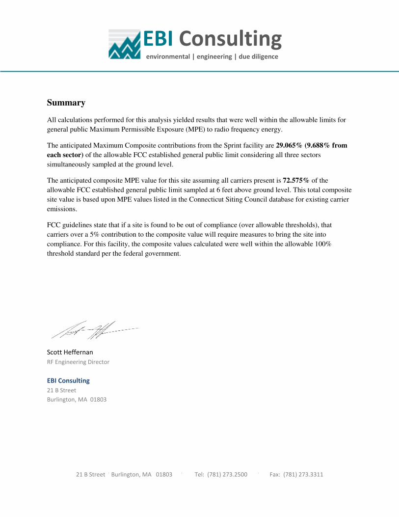
The anticipated Maximum Composite contributions from the Sprint facility are 29.065% of the allowable FCC established general public limit. The anticipated composite MPE value for this site assuming all carriers present is 72.575% of the allowable FCC established general public limit sampled at the ground level.
Site Composite MPE %
Carrier MPE %
Sprint 29.065%
Town 6.870%
AT&T 13.000%
Metro PCS 2.100%
Clearwire 0.830%
Nextel 2.540%
Verizon Wireless 15.110%
T-Mobiloe 3.060%
Total Site MPE % 72.575%
January 23, 2014
Mayor M. Saud Anwar Town of South Windsor
1540 Sullivan Avenue South Windsor, CT 06074
RE: Telecommunications Facility @ 151 Sand Hill Road, South Windsor, CT 06074
Dear Mayor Anwar,
In order to accommodate technological changes and enhance system performance in the State of Connecticut, Sprint will be changing its equipment configuration at certain cell sites.
As required by Regulations of Connecticut State Agencies (R.C.S.A.) Section 16-50j-73, the Connecticut Siting Council has been notified of the changes and will review Sprint’s proposal. Please accept this letter as notification under Section 16-50j-73 of construction which constitutes an exempt modification pursuant to R.C.S.A. Section 16-50j-72(b)(2).
The accompanying letter to the Siting Council fully describes Sprint’s proposal for the referenced cell site. However, if you have any questions or require any further information on our plans or the Siting Council’s procedures, please call me at (508) 251-0720 x 302.
Thank you,
Kri Pelletier SBA Communications Company 33 Boston Post Road West Suite 320 Marlborough, MA 01752 508-251-0720 x 302 + T 508-251-1755 + F 203-446-7700 + C [email protected]
Prepared pursuant to TIA/EIA-222-F Structural Standards for Steel Antenna Towers and Antenna Supporting Structures and the 2005 Connecticut Building Code
Structural Analysis ReportSBA Network Services, Inc.
GENERAL COMMENTS ............................................................................................................................................................7
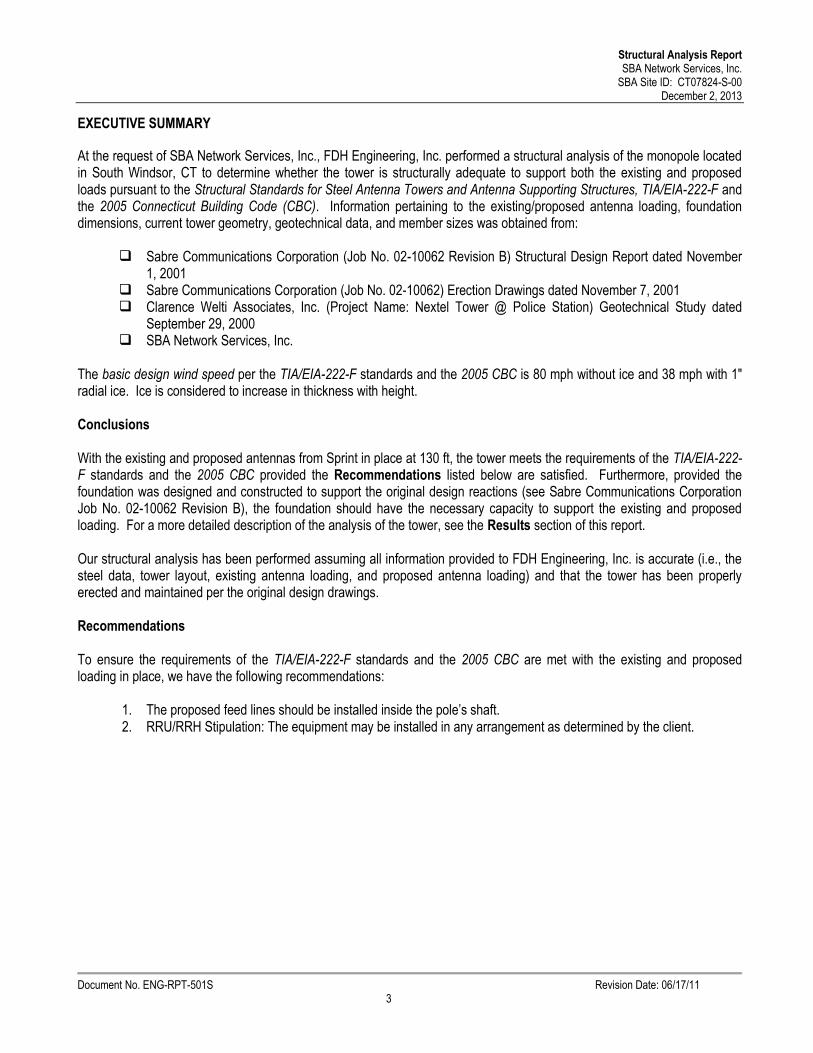
At the request of SBA Network Services, Inc., FDH Engineering, Inc. performed a structural analysis of the monopole locatedin South Windsor, CT to determine whether the tower is structurally adequate to support both the existing and proposedloads pursuant to the Structural Standards for Steel Antenna Towers and Antenna Supporting Structures, TIA/EIA-222-F andthe 2005 Connecticut Building Code (CBC). Information pertaining to the existing/proposed antenna loading, foundationdimensions, current tower geometry, geotechnical data, and member sizes was obtained from:
Sabre Communications Corporation (Job No. 02-10062) Erection Drawings dated November 7, 2001Clarence Welti Associates, Inc. (Project Name: Nextel Tower @ Police Station) Geotechnical Study dated
September 29, 2000SBA Network Services, Inc.
The basic design wind speed per the TIA/EIA-222-F standards and the 2005 CBC is 80 mph without ice and 38 mph with 1"radial ice. Ice is considered to increase in thickness with height.
Conclusions
With the existing and proposed antennas from Sprint in place at 130 ft, the tower meets the requirements of the TIA/EIA-222-F standards and the 2005 CBC provided the Recommendations listed below are satisfied. Furthermore, provided thefoundation was designed and constructed to support the original design reactions (see Sabre Communications CorporationJob No. 02-10062 Revision B), the foundation should have the necessary capacity to support the existing and proposedloading. For a more detailed description of the analysis of the tower, see the Results section of this report.
Our structural analysis has been performed assuming all information provided to FDH Engineering, Inc. is accurate (i.e., thesteel data, tower layout, existing antenna loading, and proposed antenna loading) and that the tower has been properlyerected and maintained per the original design drawings.
Recommendations
To ensure the requirements of the TIA/EIA-222-F standards and the 2005 CBC are met with the existing and proposedloading in place, we have the following recommendations:
1. The proposed feed lines should be installed inside the pole’s shaft.2. RRU/RRH Stipulation: The equipment may be installed in any arrangement as determined by the client.
Structural Analysis ReportSBA Network Services, Inc.
The proposed and existing antennas with their corresponding cables/coax lines are shown in Table 1. If the actual layoutdetermined in the field deviates from the layout, FDH Engineering, Inc. should be contacted to perform a revised analysis.
Table 1 - Appurtenance Loading
Existing Loading:AntennaElevation
(ft)Description
FeedLines1 Carrier
MountElevation
(ft)Mount Type
187
(2) Scala MF-900B Dishes(2) Telewave ANT900D6-9 Omnis
The following yield strength of steel for individual members was used for analysis:
Table 2 - Material Strength
Member Type Yield Strength
Tower Shaft Sections 65 ksi
Base Plate 60 ksi
Anchor Bolts 75 ksi
Table 3 displays the summary of the ratio (as a percentage) of force in the member to their capacities. Values greater than100% indicate locations where the maximum force in the member exceeds its capacity. Table 4 displays the maximumfoundation reactions. Table 5 displays the maximum antenna rotations at service wind speed (dishes only).
If the assumptions outlined in this report differ from actual field conditions, FDH Engineering, Inc. should be contacted toperform a revised analysis. Furthermore, as no information pertaining to the allowable twist and sway requirements for theexisting or proposed appurtenances was provided, deflection and rotation were not taken into consideration when performingthis analysis.
See the Appendix for detailed modeling information.
Table 3 - Summary of Working Percentage of Structural Components
SectionNo.
Elevationft
ComponentType
Size % Capacity*PassFail
L1 187 - 142.75 Pole TP34.17x24x0.25 40.6 PassL2 142.75 - 93.75 Pole TP44.94x32.6358x0.375 71.2 PassL3 93.75 - 46.25 Pole TP55.12x42.8101x0.4375 80.2 PassL4 46.25 - 0 Pole TP64.88x52.6344x0.5 78.1 Pass
Anchor Bolts (26) 2.25" Ø w/ BC = 72" 69.8 PassBase Plate PL 78" Ø x 2.5" Thk 63.9 Pass
*Capacities include a 1/3 allowable stress increase for wind per TIA/EIA-222-F standards.
Table 4 - Maximum Base Reactions
Base ReactionsCurrent Analysis(TIA/EIA-222-F)
Original Design(TIA/EIA-222-F)
Axial 65 k 83 kShear 41 k 48 k
Moment 5,405 k-ft 6,541 k-ft
Table 5 - Maximum Antenna Rotations at Service Wind Speeds (Dishes Only)
This engineering analysis is based upon the theoretical capacity of the structure. It is not a condition assessment of thetower and its foundation. It is the responsibility of SBA Network Services, Inc. to verify that the tower modeled and analyzedis the correct structure (with accurate antenna loading information) modeled. If there are substantial modifications to bemade or the assumptions made in this analysis are not accurate, FDH Engineering, Inc. should be notified immediately toperform a revised analysis.
LIMITATIONS
All opinions and conclusions are considered accurate to a reasonable degree of engineering certainty based upon theevidence available at the time of this report. All opinions and conclusions are subject to revision based upon receipt of newor additional/updated information. All services are provided exercising a level of care and diligence equivalent to thestandard and care of our profession. No other warranty or guarantee, expressed or implied, is offered. Our services areconfidential in nature and we will not release this report to any other party without the client’s consent. The use of thisengineering work is limited to the express purpose for which it was commissioned and it may not be reused, copied, ordistributed for any other purpose without the written consent of FDH Engineering, Inc.
Structural Analysis ReportSBA Network Services, Inc.
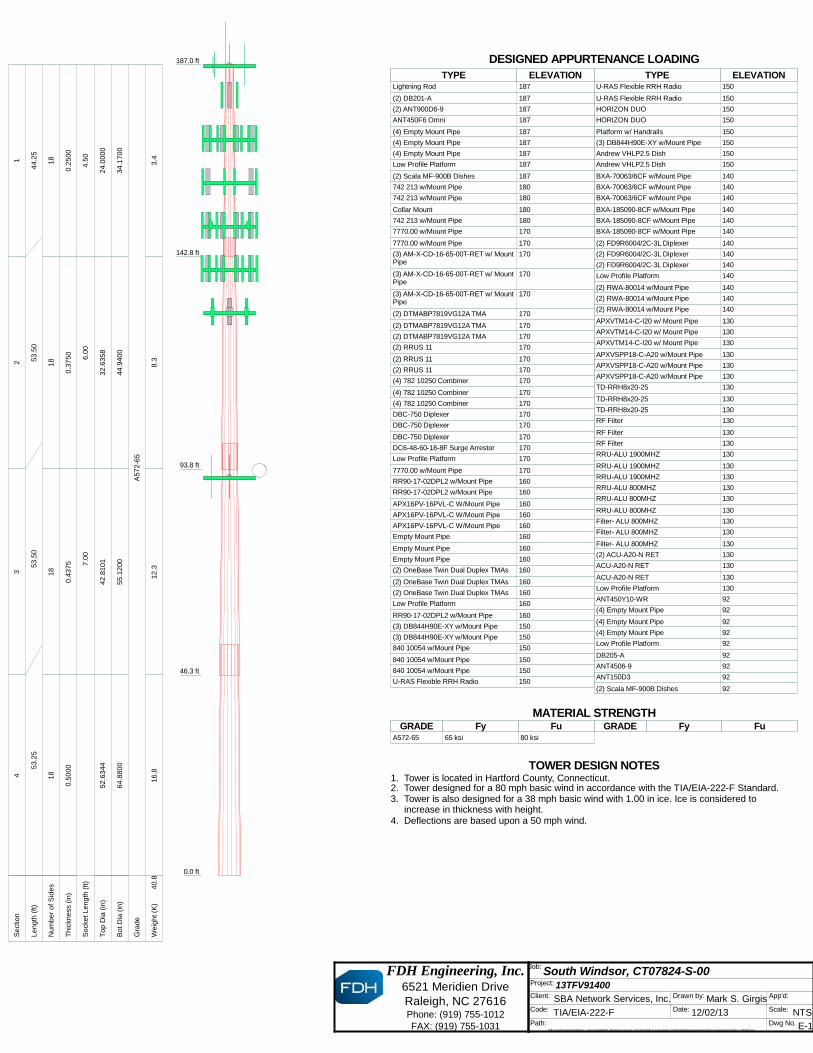
TOWER DESIGN NOTES1. Tower is located in Hartford County, Connecticut.2. Tower designed for a 80 mph basic wind in accordance with the TIA/EIA-222-F Standard.3. Tower is also designed for a 38 mph basic wind with 1.00 in ice. Ice is considered to
increase in thickness with height.4. Deflections are based upon a 50 mph wind.5. TOWER RATING: 80.2%
TOWER DESIGN NOTES1. Tower is located in Hartford County, Connecticut.2. Tower designed for a 80 mph basic wind in accordance with the TIA/EIA-222-F Standard.3. Tower is also designed for a 38 mph basic wind with 1.00 in ice. Ice is considered to
increase in thickness with height.4. Deflections are based upon a 50 mph wind.
EBI Consulting environmental | engineering | due diligence
21 B Street .
Burlington, MA 01803 .
Tel: (781) 273.2500 .
Fax: (781) 273.3311
RADIO FREQUENCY FCC REGULATORY COMPLIANCE MAXIMUM PERMISSIBLE EXPOSURE (MPE) ASSESSMENT
Sprint Existing Facility
Site ID: CT33XC555
South Windsor PD Property 151 Sand Hill Road
South Windsor, CT 06074
January 13, 2014
EBI Consulting environmental | engineering | due diligence
21 B Street .
Burlington, MA 01803 .
Tel: (781) 273.2500 .
Fax: (781) 273.3311
January 13, 2014
Sprint
Attn: RF Engineering Manager
1 International Boulevard, Suite 800
Mahwah, NJ 07495
Re: Radio Frequency Maximum Permissible Exposure (MPE) Assessment for Site:
CT33XC555– South Windsor PD Property
Site Total: 72.575% - MPE% in full compliance
EBI Consulting was directed to analyze the proposed upgrades to the existing Sprint facility located at
151 Sand Hill Road, South Windsor, CT, for the purpose of determining whether the radio frequency
(RF) exposure levels from the proposed Sprint equipment upgrades on this property are within specified
federal limits.
All information used in this report was analyzed as a percentage of current Maximum Permissible
Exposure (% MPE) as listed in the FCC OET Bulletin 65 Edition 97-01and ANSI/IEEE Std C95.1. The
FCC regulates Maximum Permissible Exposure in units of microwatts per square centimeter (µW/cm2).
The number of µW/cm2 calculated at each sample point is called the power density. The exposure limit
for power density varies depending upon the frequencies being utilized. Wireless Carriers and Paging
Services use different frequency bands each with different exposure limits, therefore it is necessary to
report results and limits in terms of percent MPE rather than power density.
All results were compared to the FCC (Federal Communications Commission) radio frequency exposure
rules, 47 CFR 1.1307(b)(1) – (b)(3), to determine compliance with the Maximum Permissible Exposure
(MPE) limits for General Population/Uncontrolled environments as defined below.
General population/uncontrolled exposure limits apply to situations in which the general public may be
exposed or in which persons who are exposed as a consequence of their employment may not be made
fully aware of the potential for exposure or cannot exercise control over their exposure. Therefore,
members of the general public would always be considered under this category when exposure is not
employment related, for example, in the case of a telecommunications tower that exposes persons in a
nearby residential area.
Public exposure to radio frequencies is regulated and enforced in units of microwatts per square
centimeter (µW/cm2). The general population exposure limit for the cellular band is approximately
567 µW/cm2, and the general population exposure limit for the 1900 MHz and 2500 MHz bands band is
1000 µW/cm2. Because each carrier will be using different frequency bands, and each frequency band has
different exposure limits, it is necessary to report percent of MPE rather than power density.
EBI Consulting environmental | engineering | due diligence
21 B Street .
Burlington, MA 01803 .
Tel: (781) 273.2500 .
Fax: (781) 273.3311
Occupational/controlled exposure limits apply to situations in which persons are exposed as a
consequence of their employment and in which those persons who are exposed have been made fully
aware of the potential for exposure and can exercise control over their exposure. Occupational/controlled
exposure limits also apply where exposure is of a transient nature as a result of incidental passage through
a location where exposure levels may be above general population/uncontrolled limits (see below), as
long as the exposed person has been made fully aware of the potential for exposure and can exercise
control over his or her exposure by leaving the area or by some other appropriate means.
Additional details can be found in FCC OET 65.
CALCULATIONS
Calculations were done for the proposed upgrades to the existing Sprint Wireless antenna facility located
at 151 Sand Hill Road, South Windsor, CT, using the equipment information listed below. All
calculations were performed per the specifications under FCC OET 65. All calculations were performed
assuming the main lobe of the antenna was focused at the base of the tower to present a worst case
scenario. Actual values seen from this site will be dramatically less than those shown in this report. For
this report the sample point is the top of a 6 foot person standing at the base of the tower.
For all calculations, all emissions were calculated using the following assumptions:
1) 3 channels in the 1900 MHz Band were considered for each sector of the proposed
installation.
2) 1 channel in the 800 MHz Band was considered for each sector of the proposed installation
3) 2 channels in the 2500 MHz Band were considered for each sector of the proposed
installation.
4) All radios at the proposed installation were considered to be running at full power and were
uncombined in their RF transmissions paths per carrier prescribed configuration. Per FCC
OET Bulletin No. 65 - Edition 97-01 recommendations to achieve the maximum anticipated
value at each sample point, all power levels emitting from the proposed antenna installation
are increased by a factor of 2.56 to account for possible in-phase reflections from the
surrounding environment. This is rarely the case, and if so, is never continuous.
5) For the following calculations the sample point was the top of a six foot person standing at
the base of the tower. The maximum gain of the antenna per the antenna manufactures
supplied specifications was used in this direction.
EBI Consulting environmental | engineering | due diligence
21 B Street .
Burlington, MA 01803 .
Tel: (781) 273.2500 .
Fax: (781) 273.3311
6) The antennas used in this modeling are the RFS APXVSPP18-C-A20 and the RFS
APXVTMM-C-120. This is based on feedback from the carrier with regards to anticipated
antenna selection. The RFS APXVSPP18-C-A20 has a 15.9 dBd gain value at its main lobe at
1900 MHz and 13.4 dBd at its main lobe for 850 MHz. The RFS APXVTMM-C-120 has a
15.9 dBd gain value at its main lobe at 2500 MHz. All calculations were performed assuming
the main lobe of the antenna was focused at the base of the tower to present a worst case
scenario.
7) The antenna mounting height centerline for the existing and proposed antennas is130 feet
above ground level (AGL).
8) Emissions values for additional carriers were taken from the Connecticut Siting Council
active database. Values in this database are provided by the individual carriers themselves.
All calculation were done with respect to uncontrolled / general public threshold limits
Site ID
Site Addresss
Site Type
Antenna
Number Antenna Make Antenna Model Radio Type Frequency Band Technology