60
Southeastern Pennsylvania Transportation Authority DESIGN CRITERIA DOCUMENT COMBINED HEATING & POWER PLANT FOR SEPTA MIDVALE SITE SEPTA RFP No.: 14-297-JFK 50 % Design Package

Southeastern Pennsylvania
Transportation Authority
DESIGN CRITERIA DOCUMENT
COMBINED HEATING & POWER PLANT FOR
SEPTA MIDVALE SITE
SEPTA RFP No.: 14-297-JFK
50 % Design Package

Design Criteria Document Combined Heating and Power Plant SEPTA Midvale CHP Page 2
TABLE OF CONTENTS
PAGE 1.0 PROJECT DESCRIPTION 5 2.0 DESIGN CRITERIA 5 2.1 CODES AND STANDARDS 5 2.2 ELECTRICAL AND THERMAL LOADS 7 2.3 EQUIPMENT DESIGN CRITERIA 10
2.3.1 Design Fuel 11 2.3.2 Water Supply 11
2.4 PLANT FUTURE EXPANSION 11 2.5 DESIGN TEMPERATURES 12 2.6 PERMITTING 12 3.0 DESIGN BASIS 13 3.1 MAJOR EQUIPMENT 13
3.1.1 CHP Equipment 13 3.1.2 Emissions 17
3.2 HEATING HOT WATER SYSTEM 18
3.2.1 General 18 3.2.2 Summary of Design Conditions 19
3.3 NATURAL GAS SYSTEM 20 3.4 CHEMICAL TREATMENT 20
3.4.1 Heating Hot Water Treatment 20
3.5 COOLING WATER SYSTEMS 21 3.5.1 Radiators 21 3.5.2 Cooling Water Distribution 21
3.6 PLUMBING SYSTEMS 21 3.7 HVAC SYSTEM 22 3.8 ELECTRICAL SYSTEMS 22
3.8.1 Electric Distribution System 22 3.8.2 CHP System Engine Generator 23 3.8.3 Operating Description 23 3.8.4 CHP Plant DC Systems 24 3.8.5 Electrical Distribution System Monitoring 24 3.8.6 Site Conditions 25

Design Criteria Document Combined Heating and Power Plant SEPTA Midvale CHP Page 3
3.8.7 Design Summary 25 3.8.8 Design Requirements 26 3.8.9 Design Criteria 27 3.8.10 Load Criteria 28 3.8.11 Protective Relaying 29 3.8.12 DC Systems 29 3.8.13 UPS 30 3.8.14 Electrical Equipment 30 3.8.15 Switchgear 31 3.8.16 Power Transformers 31 3.8.17 Motor Controllers 32 3.8.18 Panelboards and Transformers 32 3.8.19 Grounding 33 3.8.20 Lighting 34 3.8.21 Conduit and Conduit Fittings 34 3.8.22 Cable Trays 36 3.8.23 Power and Control Wiring 36 3.8.24 Control Systems Instrumentation 38
3.9 INSTRUMENTATION AND CONTROL SYSTEMS 39
3.9.1 System Integration 40 3.9.2 PCS Hardware Overview 42 3.9.2.1 PCS-PAC Control Panel 42 3.9.2.2 PCS-Operator Interface (HMI) 45
3.9.3 CHP Plant Sub-Systems Controls Interfaces 47 3.9.3.1 Engine Generator 47 3.9.3.2 SCR Systems 48 3.9.3.3 Engine Radiator System 48 3.9.3.4 Water Treatment Systems 48 3.9.3.5 Electrical generation and Distribution System 48 3.9.3.6 Fuel Delivery System 49 3.9.3.7 Compressed Air System 49 3.9.3.8 Building Ventilation Fan Control 49 3.9.3.9 Continuous Emissions Monitoring System 49 3.9.4 Miscellaneous Equipment Status 49 3.9.5 Instrumentation 50 3.9.5.1 Pressure Gauges 50 3.9.5.2 Temperature Gauge 50 3.9.5.3 Temperature Sensor 50 3.9.5.4 Pressure Transmitter 50 3.9.5.5 Flow Meters 50 3.9.5.6 Level Transmitters 50 3.9.5.7Pressure Switches 50 3.9.5.8 Level Switches 50
3.10 COMPRESSED AIR SYSTEM 51 3.10.1 Instrument Air System 51

Design Criteria Document Combined Heating and Power Plant SEPTA Midvale CHP Page 4
3.10.2 Service Air System 51 3.11 FIRE PROTECTION DESIGN CRITERIA 51
3.11.1 General Conditions 51 3.11.2 Buildings 51 3.11.3 Fire Protection Water Supply 52
3.12 STRUCTURAL DESIGN CRITERIA 53
3.12.1 Building Code 53 3.12.2 Building General Data 54 3.12.3 Foundation Systems 54 3.12.4 Building Steel Frame 55 3.12.5 Exterior Walls 55 3.12.6 Roof 56 3.12.7 Interior Partitions 56 3.12.8 Interior Finishes 56 3.12.9 Doors 57 3.12.10 Weather seals 57 3.12.11 Windows 57 3.12.12 Misc. Structural Steel Supports 57 3.12.13 Platforms 58
4.0 MISCELLANEOUS SYSTEMS 58 4.1 INTERCONNECTION POINTS 58
4.1.1 Electric Feeders 58 4.1.2 Hot Water Distribution System 58 4.1.3 CHP Utilities 58
4.2 CIVIL DESIGN CRITERIA 59
4.2.1 General 59 4.2.2 Permitting 59 4.2.3 Cut, Fill and Compaction 59 4.2.4 Erosion & Sedimentation Control and Stormwater Management 59 4.2.5 Site Utilities 60 4.2.6 Site Improvements 60 4.2.7 References 60
Design Criteria Document Combined Heating and Power Plant SEPTA Midvale CHP Page 5
1.0 PROJECT DESCRIPTION
SEPTA’s Wayne Junction’s static converter plant provides 25 Hz traction power system to operate SEPTA’s trains in the Philadelphia corridor. Power is received from PECO’s transmission system at 230 kV, 60 Hz at the Wayne Junction site and is transformed down to 13.2 kV before converting to 25 Hz via the three static frequency converters. SEPTA plans to generate electricity from natural gas at the Midvale site to supply electricity to (1) the Midvale site for primary power needs and (2) the Wayne Junction site to be used as the base load power, with PECO Energy’s 230 kV supply as peak and back up electric capacity. The Combined Heating and Power (CHP) plant will include two skid mounted engine generators, high voltage electric infrastructure equipment and miscellaneous appurtenances. Within this and other project documents, this cogeneration equipment is referred to as the CHP system. Emissions control equipment will be included with the CHP system equipment. The CHP plant will be located on SEPTA’s Midvale property in Philadelphia in the area between the Roberts yard and Midvale. The CHP plant will be a new building containing electric generation via the two engine generators and high voltage electrical distribution. Space will be allocated for a future additional engine generator of the same size. Electrical power distribution to the SEPTA 13.2 kV 60 Hz bus will be via new aerial cable connecting Midvale to Wayne Junction Tie-in to SEPTA’s electrical system shall be at the existing plant 13.2 kV switchgear bus. The electrical connection between the CHP plant and the Midvale site will be made at 13.2 kv substation located on the site. Hot water from the engine generator jacket water system shall be provided to SEPTA for heating in occupied buildings located on the Midvale and Roberts yard properties via heat exchangers located in the new CHP building. The complete hot water system will be maintained by the CHP plant operator. The CHP plant operator shall have no responsibility beyond the electrical tie-in points at Wayne Junction and Midvale facility except for the heating hot water loop. Communication for control, operation, status and maintenance of the energy infrastructure originating from the CHP plant as well as the required interfaces with the SEPTA’s building automation and management and life safety systems shall be provided by a fiber optic network and communication link. Design and construction activities shall be coordinated to maintain steam and electrical services to the existing operating prison areas throughout the construction period.
2.0 DESIGN CRITERIA
2.1 CODES AND STANDARDS
The plant shall be designed and constructed in compliance with all applicable code and standards as required by authorities having jurisdiction. The following is a list (though not all inclusive) of associations and societies that publish the applicable codes.

Design Criteria Document Combined Heating and Power Plant SEPTA Midvale CHP Page 6
AMCA Air Movement and Control Association ACI American Concrete Institute
AGMA American Gear Manufacturers Association AISC American Institute of Steel Construction AISI American Iron and Steel Institute ASCE American Society of Civil Engineers ASHRAE American Society of Heating, Refrigerating, and Air Conditioning Engineers ANSI American National Standards Institute ASTM American Society of Testing and Materials ASME American Society of Mechanical Engineers AWS American Welding Society EIA Electronic Industries Association RS232-C/RS422, RS485
Communications Protocols EPA Environmental Protection Agency FM Factory Mutual HEI Heat Exchange Institute HI Hydraulic Institute IEEE Institute of Electrical & Electronics Engineers IBC International Building Code IGCI Industrial Gas Cleaning Institute ICEA Insulated Cable Engineers Association ISA International Society of Automation NEC National Electric Code NEMA National Electrical Manufacturers Association NFPA National Fire Protection Association PADEP Pennsylvania Department of Environmental Protection PAUCC Pennsylvania Uniform Construction Code OSHA Occupational Safety and Health Act SAMA Scientific Apparatus Makers Association SSPC Steel Structures Painting Council TEMA Tubular Exchangers Manufacturers Association UL Underwriters Laboratories
In addition, the design and construction of the facility shall comply with the requirements of the following agencies or entities:
PECO Energy Commonwealth of Pennsylvania City of Philadelphia
Code Type Code Model Building Code IBC 2009 Structural Code IBC 2009 Plumbing Code Philadelphia Plumbing Code Mechanical Code IMC 2009 Electrical Code IBC 2009, Ch. 27 (Must comply w/NEC 2008) Fire/Life Safety Code IFC 2009 Accessibility Code IBC 2009, Ch. 11 & ICC/ANSI A117.1-2003
Design Criteria Document Combined Heating and Power Plant SEPTA Midvale CHP Page 7
Energy Code IECC 2009 2.2 ELECTRICAL AND THERMAL LOADS The electrical minimum and normal loads for the Wayne Junction facility and future planned areas are determined from electrical bills and submetering data provided by PECO and SEPTA. The table below details the projected electrical loads at the Wayne Junction facility for the next twenty years. The data is based on bi-hourly, 60 Hz metering data provided by PECO. The data was collected from August 2010 to July 2011. The projected load is assumed to increase 10% by the time plant construction is complete. The load is assumed to increase 2.5% annually.
SEPTA Wayne Junction Electrical Load Projections
Year Calculated Yearly
Electrical Load (KWH/YR)
Calculated Avg Electrical Load
(KW)
Calculated Max Electrical Load
(KW)
Calculated Min Electrical Load
(KW) 1 104,318,446 11,910 27,419 3,612 7 120,977,416 13,812 31,798 4,188
12 136,874,842 15,627 35,976 4,739 20 166,768,704 19,040 43,833 5,774

Design Criteria Document Combined Heating and Power Plant SEPTA Midvale CHP Page 8
The electrical load duration curve below is based on the projected year one electrical load at Wayne Junction.
0
5000
10000
15000
20000
25000
30000
0 1000 2000 3000 4000 5000 6000 7000 8000 9000 10000
ELEC
TRIC
AL L
OAD
(kW
)
HOURS PER YEAR
SEPTA WAYNE JUNCTION ELECTRICAL LOAD DURATION CURVE - YEAR 1

Design Criteria Document Combined Heating and Power Plant SEPTA Midvale CHP Page 9
The two graphs below show the Wayne Junction electrical load for an interval of one day each. The two graphs detail a weekday and a weekend day, respectively. The data is adjusted to represent year one projected loads. The graphs are based on metered data provided by SEPTA.
0
5000
10000
15000
20000
25000
30000
35000
40000
45000
50000
0:00 2:24 4:48 7:12 9:36 12:00 14:24 16:48 19:12 21:36
Elec
tric
al L
oad
(kW
)
TIME
SEPTA Wayne Junction Electrical Load - Typical Weekday
Based on 07/11/11 Data

Design Criteria Document Combined Heating and Power Plant SEPTA Midvale CHP Page 10
The Energy usage information for the Midvale site for 12 months (2013) is shown in the table below. Total Energy Usage ( kWh) 7,258,912 Total Weekday Energy Usage ( kWh) 5,241,919 Total Weekend Energy Usage ( kWh) 2,016,993 Weekday Maximum Demand ( kW) 1,061 Weekend Maximum Demand ( kW) 1,045 Power Factor at Time of Maximum Demand 88.91% Load Factor 78.08% On-Peak - Total Energy ( kWh) 2,414,381 On-Peak - Maximum Demand ( kW) 1,043 On-Peak - Maximum Demand Time 07/18/2013 19:30 Off-Peak - Total Energy ( kWh) 4,844,531 Off-Peak - Maximum Demand ( kW) 1,061 Off-Peak - Maximum Demand Time 07/18/2013 21:00
0
5000
10000
15000
20000
25000
30000
35000
40000
45000
50000
3:19 5:43 8:07 10:31 12:55 15:19 17:43 20:07 22:31
Elec
tric
al L
oad
(kW
)
TIME
SEPTA Wayne Junction Electrical Load - Typical Weekend
Based on 07/10/11 Data

Design Criteria Document Combined Heating and Power Plant SEPTA Midvale CHP Page 11
2.3 EQUIPMENT DESIGN CRITERIA
Finish Floor Elevation Above Sea Level: 354’ Outdoor Design High Temperature: 90 °F dry bulb Outdoor Design Low Temperature: 10 °F (zero wind speed) Design Wind Speed (UCC): 90 mph Design Wind Exposure (UCC): “C” Snow Load (PA Building Code): 30 PSF Seismic Coefficients (UCC): (Per UCC including latest PA
Amendments) Design Wet Bulb Temperature: 75.5 °F
2.3.1 Design Fuel Percent by Percent by
Natural Gas Volume Weight (Confirm actual fuel gas content with PGW. Values below are for reference only) Nitrogen, N2 4.9892 8.0604 Methane, CH4 90.0000 83.2506 Ethane, C2H6 5.0000 8.6705 Sulfur, S 0.0108 0.0185 Total 100.0000 100.0000 High Heating Value, Btu/lb 22,429.83 @ 60 °F & 30” Hg Btu/cu ft 1030.00 Gas Supply Pressure, psig TBD
2.3.2 Water Supply
Result
Total Dissolved Solids (TDS) TBD Total Hardness, ppm 166 Alkalinity, ppm 68 Sulfite, TBD Iron TBD Copper, ppm 0.3 pH TBD Delivery Pressure, psig: TBD It is recommended that the final design of the CHP plant be based on the most current water analysis.

Design Criteria Document Combined Heating and Power Plant SEPTA Midvale CHP Page 12
2.4 PLANT FUTURE EXPANSION
The CHP plant shall be designed in a manner that will accommodate future loads associated with the expected increasing electric load. The plant drawings include space for a future engine generator and associated SCR and auxiliary equipment. The cabling between the Midvale CHP Plant and tie in at Wayne Junction shall be sized to accommodate future expansion of up to 50 MW of generation capacity. It is not expected that the hot water load will be increasing in the future at SEPTA’s Midvale/Roberts property, so it is not expected that the hot water from the future engine generator will be recovered for heating purposes, though it could be tied into the existing hot water heating loop for redundant capacity.
2.5 DESIGN TEMPERATURES Ambient outdoor temperatures to be used for design of the HVAC and Utility systems will be based on site design data tabulated in the 2009 ASHRAE Handbook of Fundamentals for Northeast Philadelphia Airport, Pennsylvania. Design will be based on the following ambient climate conditions:
Winter Temperature: 15.6 ° Fahrenheit Dry Bulb (99% Occurrence).
Summer Temperature: 90.4°F Dry Bulb (1% Occurrence) 77.0 °F Mean Coincident Wet Bulb Temperature (1%
Occurrence)
Indoor temperatures to be used for the design of the heating ventilating and air conditioning systems are as follows:
Engine Area and Mezzanine:
Winter Temperature: 60 °F Summer Temperature: 104 °F Electrical Room:
Winter Temperature: 60 °F Summer Temperature: 104 °F
Control Room: Winter 70 °F Summer 75 °F and 50% RH

Design Criteria Document Combined Heating and Power Plant SEPTA Midvale CHP Page 13
2.6 PERMITTING
All required state and local permits shall be obtained before construction commences on the CHP plant. Permits shall include: • Pennsylvania Construction permit • Philadelphia Building Permit • Soil Erosion and Sediment Control permit – any disturbance over 5000 ft2. • PADEP Air Permit –Permit submittal to authorities having jurisdiction should be as
early in the design process as possible. Permit requirements could potentially impact equipment design.
• Philadelphia Air Management • PECO Energy – Coordinate with utility and provide design and construction
documents for higher than normal gas pressure connection to meet utility requirements.
3.0 DESIGN BASIS
The two engine generators will be load following operating continuously as long as the load is adequate to operate the engine without impacting the air emissions regulations (approximately 50% of 8000 kW). At loads below 50% one of the engine generators will be shut down to allow the second machine to operate within its emissions limits. The maximum load produced by both engine generators will be approximately 8,000 KW (at 59 °F ambient) of electricity for conversion to traction power use at SEPTA’s Wayne Junction frequency converter station. The actual loading of the engine generators will follow the loading curves illustrated in Section 3.1.1 below. The hot water circuit from these units will be directed through plate and frame heat exchangers to provide heating to adjacent buildings during heating months. The combined engine heat recovery system is capable of adding 7,097 MBH (3,425 MBH exhaust gas and 2,795 MBH jacket water) of heat to the hot water system for heating purposes. All thermal capacity will be directed to the radiators during the non-heating months of the year. The engine generator will be fired on natural gas only.
3.1 MAJOR EQUIPMENT Features of the new major equipment and systems are summarized in the sections that follow.
3.1.1 Cogeneration Equipment
The cogeneration unit will utilize two, 4,000 ekW (minimum), natural gas fueled reciprocating engine generator sets. The units will be rated for continuous duty at the rated output. The units will be self-contained and skid mounted, with each engine and generator on a single structural steel base.

Design Criteria Document Combined Heating and Power Plant SEPTA Midvale CHP Page 14
The engines will be designed to run on natural gas fuel only, and will require a natural gas pressure of approximately 1.5-5 psig for the main gas supply, and 61 psig natural gas pressure for the pre-chamber (approximately 4% of the overall gas requirement). A small 7.5 HP gas compressor is included with each engine package for the pre-chamber supply. The developer is responsible for working with Philadelphia Gas Works (PGW) to provide a natural gas supply line to the CHP. It will be necessary to include a gas pressure-reducing valve (PRV) for each engine generator to maintain constant inlet pressure.
The engine will be equipped for recovery of waste heat from the high temperature water system only. The waste heat recovery system is comprised of a plate and frame heat exchanger and a booster pump for each, feeding a loop through the building’(s) unit heaters (new hot water unit heaters to be supplied by SEPTA or as an alternate by the developer).
During the heating season, the waste heat recovery system will be the base loaded heating source for the Midvale/Roberts Sites, with the existing steam boilers acting as peaking and back up capacity. The return hot water entering at 170 °F will pass through a plate and frame heat exchanger which will be heated with high temperature engine cooling water, which transfers heat to the return hot water. The return water is heated to a supply temperature of 195 °F. The two engines will each be maintained by a Class “C” underhung crane (1 for each engine) with an H-4 hoist sized to enable lifts of 2,200 lbs.
During the cooling season, the waste heat recovery system will not be used, and all hot water circuit heat removal will be done through the radiators.
The performance of a natural gas engine is relatively constant over normal facility conditions and over most of the power range. The anticipated performance for each engine is as follows:
Acceptable Manufacturers: Caterpillar, Cummins, GeJenbacher, Waukesha or MWM
Gross Electric Power: 4,000 kW – 4,500 kW Engine Natural Gas Fuel Flow (LHV): 15.71 MMbtu/Hr Heat Recovered from Exhaust Gas: 0 MMbtu/Hr Heat Recovered from Jacket Water: 2. 795 MMbtu/Hr Heat Recovered from Intercooler: 3.425 MMbtu/Hr Heat Recovered from Lube Oil: 0.877 MMbtu/Hr Total Heat Recovered: 7.097 MMbtu/Hr

Design Criteria Document Combined Heating and Power Plant SEPTA Midvale CHP Page 15
SEPTA Wayne Junction Electrical Load Projections
Year
Calculated Yearly
Electric Load
(kWh/Yr)
Total Electrical Capacity
(kW)
Total Generated Electricity (kWh/Yr)
Percent of SEPTA Load
Generated
Avg Generated Electricity
(kW)
Percent of Capacity
Generated
Engine Heat Rate (BTU/kWh)
Fuel Consumption
(MMbtu/Yr)
1 104,318,446
8,600
54,964,885 52.7% 6,275 73.0%
7,445
409,214 7 120,977,416 61,671,610 51.0% 7,040 81.9% 459,145 12 136,874,842 66,516,224 48.6% 7,593 88.3% 495,213 20 166,768,704 71,907,725 43.1% 8,209 95.4% 535,353
0
5000
10000
15000
20000
25000
30000
0 2000 4000 6000 8000 10000
ELEC
TRIC
AL L
OAD
(kW
)
HOURS PER YEAR
SEPTA WAYNE JUNCTION ELECTRICAL LOAD DURATION CURVE ELECTRICAL OUTPUT SEPTA Electrical Load
8,600 KW Recip Engines
4 MW
Design Criteria Document Combined Heating and Power Plant SEPTA Midvale CHP Page 16
0
5000
10000
15000
20000
25000
30000
35000
40000
45000
50000
0:00 2:24 4:48 7:12 9:36 12:00 14:24 16:48 19:12 21:36
Elec
tric
al L
oad
(kW
)
TIME
SEPTA Wayne Junction Electrical Load - Typical Weekday Based on 07/11/11 Data Electrical Load
8,600 KW Recip Engines

Design Criteria Document Combined Heating and Power Plant SEPTA Midvale CHP Page 17
3.1.2 Emissions
The proposed new facility is located in Philadelphia, and as such, is in one of the five counties which is part of the Philadelphia Metropolitan Severe Non-Attainment Area for troposphere ozone that would be subject to New Source Review (NSR) permitting requirements. It must also be in compliance with the latest New Source Performance Standards (40 CFR Part 60 Subpart JJJJ) and the National Emission Standards for Hazardous Air Pollutants (40 CFR Part 63 Subpart ZZZZ). Since the new facility is planned to be owned and operated by a third-party energy supplier, the PADEP will most likely consider that this facility is not contiguous with the SEPTA buildings (with steam boilers) and/or located on adjacent properties under common control. The CHP owner must determine what the PADEP requirements are for this arrangement. As such, the design basis assumes that the existing facility would retain their current operating permit, but the new CHP plant would minimally be subject to the state Plan Approval permit process. The CHP system design is currently configured for low NOx and CO emissions, and will include an SCR and Oxidation catalyst.
0
5000
10000
15000
20000
25000
30000
35000
40000
45000
50000
3:19 5:43 8:07 10:31 12:55 15:19 17:43 20:07 22:31
Elec
tric
al L
oad
(kW
)
TIME
SEPTA Wayne Junction Electrical Load - Typical Weekend Based on 07/10/11 Data Electrical Load
8,600 KW Recip Engines
Design Criteria Document Combined Heating and Power Plant SEPTA Midvale CHP Page 18
Since both NOx and VOCs are considered precursor pollutants for the formation of ozone, any incremental increase in NOx and/or VOCs emissions that is greater than 25 tons per year for either air pollutant associated with the proposed project would trigger NSR/Title V permitting requirements. With the add-on control systems planned for NOx and CO, it is not anticipated that this CHP facility will trigger NSR/Title V permitting requirements. The Philadelphia Air Management Services (AMS) is independently responsible for administrating and enforcing the PADEP regulations in Philadelphia County and/or establishing and enforcing more stringent regulations. The AMS will be the lead agency that will be responsible for reviewing and issuing the air permit for the proposed project. The CHP owner must work with SEPTA to complete the AMS permitting requirements. The Plan Approval submission will represent a request for a ‘state only synthetic minor” permitting status under the Plan Approval permitting process.
Combustible Gas Detection System The combustible gas detection system shall have an all solid-state, single channel combustible gas monitor with a fully adjustable low gas level detection circuit and fully adjustable high gas level detection circuit. The circuit shall have time delay on start up to prevent false alarms during stabilization of sensors. A gas sensor is located to continuously monitor entire volume inside the CHP building for the presence of combustible gases. The gas sensor shall be listed for use in a Class I, Division II hazardous (classified) location. It shall alarm on operation of low gas level detection circuit, operation of high gas level detection and failure of gas detection system. It shall shut down the engine generator units on operation of low gas level detection circuit and operation of high gas level detection. A portable kit complete with gas cylinder, regulator, gauge, valve and extension tube to calibrate gas monitor is to be provided.
3.2 HEATING HOT WATER SYSTEM 3.2.1 General
The Contractor shall be responsible for the mechanical design signed and sealed by a professional engineer in the Commonwealth of Pennsylvania. Existing conditions to be field verified prior to construction.
Hot water will be captured from the jackets of both of the generator engines, piped through plate and frame heat exchangers, and pumped below grade to the Midvale and Roberts buildings via distribution pumps located in the CHP plant. The hot water distribution piping will be installed in the CHP plant and will be a looped supply and return within SEPTA’s building(s) operated and maintained by the CHP owner. The below grade hot water distribution piping between the CHP plant and the Midvale and Roberts buildings shall be pre-insulated steel carrier pipe with polyurethane foam insulation and PVC jacket. Provide capped hot water supply and return pipes at both sites for future connection. Refer to drawings for pipe sizes and proposed routing. Contractor shall install a data communication underground in 1” PVC conduit that, combined with its associated pull boxes, allow for the installation of fiber optic cable. This

Design Criteria Document Combined Heating and Power Plant SEPTA Midvale CHP Page 19
will enable real time data communication and control between the SEPTA building(s) and the CHP plant. Coordinate exact location of all new piping and equipment with SEPTA. The contractor is responsible for all piping and equipment support, electrical connection, controls Contractor responsible for the mechanical design signed and sealed by a professional engineer in the Commonwealth of Pennsylvania. Existing conditions to be field verified prior to construction.
3.2.2 Summary of Design Conditions
Pipe Velocities: Above ground hot water mains 1.8 - 10.5 fpm Temperatures at the CHP plant:
353 °F Design Maximum hot water supply 180 °F Maximum hot water return 160 °F Minimum hot water supply 170 °F Minimum hot water return 150 °F Maximum System Operating Pressures: Hot water 150 psig System Design Pressures: Hot water piping & fittings 150 psig Plate-and-frame HX design 150 psig System Test Pressures: Hot water piping & fittings 225 psig Minimum Slope for Drainage: Hot water 1”/100 feet
3.3 NATURAL GAS SYSTEM
Delivery of the main gas supply shall be the responsibility of the Developer. The gas distribution system shall be routed from Philadelphia Gas Works (PGW) meter to the engine generators. Coordination with PGW is needed to determine the location of this gas meter and the tariff optimum for this service.
The gas system shall be installed in accordance with PGW requirements and all local codes. The natural gas shall be treated as necessary (filtered) to meet the specifications of the engine generators.

Design Criteria Document Combined Heating and Power Plant SEPTA Midvale CHP Page 20
The main gas train shall consist of: • Manual shut off valve • Gas filter, filter fineness <3 µm • Adapter with dismount to the pre-chamber gas train • Gas admission pressure regulator • Pressure gauge with push button valve; 0-7.25 psi (0-500 mbar) • Solenoid valves • Gas pressure switch (min.) • Leakage detector • Gas pressure regulator • Gas flow meter • Pressure/temperature compensation
3.4 CHEMICAL TREATMENT
3.4.1 Heating Hot Water Treatment
As a minimum, a corrosion inhibitor chemical such as phosphate for the optional heating hot water system shall be provided. The chemicals recommended by a water-treatment system manufacturer will be compatible with piping system components and connected equipment. The system shall be automatic based upon water make up rate or system flows.
The chemical feed system will include metering pumps (2 x 100% for each chemical), stainless steel distribution tubing, injection quills or headers in the equipment and storage for chemical containers. Product should be available in a single container, drumless delivery form.
3.5 COOLING WATER SYSTEMS
3.5.1 Radiators
The engine generators high temperature and low temperature cooling water loops will be cooled by individual radiators for each system. The radiators will be located on the ground outside of the CHP plant building. Each radiator will be supplied with variable speed fans to control leaving water temperature to 165 °F as needed for the high temperature cooling water loop return to the engine generator.

Design Criteria Document Combined Heating and Power Plant SEPTA Midvale CHP Page 21
3.5.2 Cooling Water Distribution
Distribution of cooling water shall be provided by a cooling water pumping system consisting of four (4) variable speed cooling water pumps located in the CHP plant. The pumps are sized for the high temperature and low temperature engine cooling water circuits. The high temperature and low temperature circuits are each separate loops, and the two engines have completely separate loops also, although the high temp and low temp circuit for each engine have a cross tie with a normally closed valve to enable the radiator for one engine to serve the other, if needed. The cooling water pump system shall contain pumps, valves, gauges and accessories, piping headers and 6 or 12-pulse variable frequency drives.
3.6 PLUMBING SYSTEMS
Plumbing systems will be provided to serve the CHP plant sump and safety shower drain within the new building. Sanitary and storm drainage and potable water system piping will be extended from tie-in points located on site and extended into the new building. City water shall be tied in to the site main. A meter will be installed inside the building. Sanitary waste from the building will flow by gravity to the site sewer system. Roof drainage will be via sloped roofs, roof drains, horizontal and vertical rain water conductors to the existing underground site storm drainage system. Roof drains shall be epoxy coated cast iron, and the storm drain shall be PVC.
Plumbing fixtures shall be vitreous china, wall mounted. Handicap fixtures shall be provided where required. Flow control fittings or water saving fixtures will be utilized where appropriate and/or required for conservation. An oil/water separator will be supplied for the process areas. Hot water to fixtures will be generated through the use of an instantaneous electric type water heater. Above ground sanitary drain, waste and vent piping shall be PVC pipe and fittings. Below ground piping shall be schedule 40 PVC. Above ground potable water piping shall be type L copper with wrought copper fittings. Below ground piping will cement lined ductile iron. Piping insulation will be pre-formed fiberglass with all service jacket.
3.7 HVAC SYSTEM
During summer operation the CHP plant will be provided with sufficient ventilation in the engine generator and electrical equipment areas to offset the heat gain from the equipment, piping, motors, electrical equipment and all miscellaneous equipment. The

Design Criteria Document Combined Heating and Power Plant SEPTA Midvale CHP Page 22
CHP plant shall be designed for a 9 °F rise and a minimum temperature of 60 °F. Supply air fans located in an adjacent louvered fan room will force outside air into CHP plant ducting. CHP plant ducting will direct outside air to generator area. Wall mounted exhaust fans located at South end of plant will exhaust plant air outdoors. Supply and exhaust fans will be operated with VFDs to control plant room temperature. Electric unit heaters will be installed to maintain design temperatures during winter operation. The control room will be provided with a Heating and Air Conditioning direct expansion system with heat pump option to maintain design temperatures. The system shall consist of an Air Handling Unit, condensing unit and a duct distribution system with Electric Split-System for back-up.
3.8 ELECTRICAL SYSTEMS
This section is a general description of the electrical design, equipment, and materials. Voltage insulation levels, interrupting capacities, continuous current capacities, circuit protection, and mechanical strengths shall be selected and coordinated in accordance with calculations and the requirements of IEEE, NEMA, ICEA, ANSI, and NFPA. System protective devices (relays, fuses, breaker trip unit, etc.) shall be selected and coordinated to ensure that the interrupter nearest the point of a short circuit will open first and minimize disturbances on the rest of the system.
3.8.1 Electrical Distribution System
Power to each CHP engine generator will be derived from new 13.2 kV switchgear (SG1301). The CHP electrical distribution system will be arranged as a double-ended configuration configured with Main-Tie-Main circuit breakers, and feeder circuit breakers. The main switchgear will include automatic & manual transfer controls, with closed/open transition and re-transfer. The CHP 13.2 kV switchgear will be equipped with 1200 A, draw-out, vacuum type power circuit breakers with multi-function protective relays and meters. Duct lines and 15 kV power feeders to the existing SEPTA 13.2 kV switchgear will also be provided. The new 13.2 kV switchgear will operate in parallel with the utility. In the event that the PECO service connections are lost, the engine generators will shut down. A single 13.2 kV-480 V 750-kVA, oil filled transformer will be provided fed from the 13.2 kV CHP switchgear to provide auxiliary power to the CHP system. The transformer secondary will feed a motor control center (MCC 0401). The motor control center will include pumps and fans associated with the operation of the CHP plant and building enclosure.
3.8.2 CHP System Engine Generator The CHP System engine generators will each be rated at a minimum 4000 eKW and supplied by an approved manufacturer. The generator will be operated at 13.2KV.

Design Criteria Document Combined Heating and Power Plant SEPTA Midvale CHP Page 23
A generator circuit breaker will be located in the SG-1301 switchgear. A Beckwith 3425A protective relay will be provided for generator protection. The engine generator will normally operate in parallel with the utility in a base loaded cogeneration mode. The system shall be designed for isolated operation and be capable of supplying power to Septa’s Wayne Junction without the assistance of the utility grid.
3.8.3 Operating Description
Normal SEPTA Operations – Both SEPTA Buses Energized – Tie Breaker Open – All Three Frequency Converters in Operation
1. CHP Service Switchgear SG1301 – Main circuit breakers MF1, MF2 are closed, CHP Bus Tie breaker T-1 is open. (The bus-tie circuit breaker will normally be open).
2. Each engine generator is operating in parallel with utility. 3. If the SEPTA plant load on each CHP bus drops below 50% of each engine
generator, both engine generators shall trip off line and all power will be imported from the utility.
4. If the loading of one of the two engine generators drops below 50%, that engine generator will be shut down and the corresponding generator circuit breaker open. The other running engine generator shall remain on line to provide power to the SEPTA plant bus unless that load also drops below 50%.
Normal SEPTA Operations – Both SEPTA Buses Energized – Tie Breaker Open – Only Two Frequency Converters in Operation on SEPTA 13.2 kV Bus “1”
1. CHP Service Switchgear SG1301 – Main circuit breaker MF1 will be closed and main circuit breaker MF2 will be open to match the SEPTA bus loading arrangement, CHP Bus Tie Breaker T-1 will be closed.
2. Both engine generators will operate in parallel with utility via the operating SEPTA frequency converters.
3. If the SEPTA plant load drops below 50% one of the engine generators shall trip off line and its generator circuit breaker shall open. The remaining engine generator shall provide power up to its full load capacity.
SEPTA Plant Bus Operating With One Main Breaker Open and the SEPTA Plant Bus Tie Closed 1. CHP Service Switchgear SG1301 – One circuit breaker will be closed and one
main circuit breaker open to match the SEPTA bus arrangement, CHP Bus Tie Breaker T-1 will be closed.
2. Both engine generators will operate in parallel with utility via the operating SEPTA bus.
3. If the SEPTA plant load drops below 50% one of the engine generators shall trip off line and its generator circuit breaker shall open. The remaining engine generator shall provide power up to its full load capacity.
Loss of Both Engine Generators
1. Import required power from utility.

Design Criteria Document Combined Heating and Power Plant SEPTA Midvale CHP Page 24
Loss of Utility during Normal Operations
1. If both PECO services are lost, protective relays associated with the main CHP switchgear (SG1301) will trip both CHP Generator breakers. CHP Plant will then be restarted in isolation (island) mode without utility grid according to restoration procedures to be developed.
Restoration of Utility Source
1. Upon restoration of stable utility sources, the operator will synchronize the CHP engine generator and utility source according to restoration procedures to be developed.
3.8.4 CHP Plant DC Systems
The CHP plant will be provided with a 125 V dc system consisting of maintenance-free battery cells, battery charger, and dc distribution panelboard. This system will provide power to the 13.2 kV normal switchgear (SG-1301) and controls. Each CHP engine generator will be provided with a 24 V battery system for operation of selected engine and generator controls and starting the engine.
3.8.5 Electrical Distribution System Monitoring
Monitoring of power flow in the CHP electrical distribution system will be accomplished with electronic meters located on the main and feeder circuit breakers. These meters will provide local indication and will also communicate with the Plant Control System via Ethernet (Modbus/TCP). Monitoring of breaker status (position), protective relay operations, etc., switchgear alarms, etc. will be hard wired to the Plant Control System. Data for monitoring of power flow and equipment status required by PECO Energy will be hard wired to SCADA RTUs furnished and installed by PECO Energy. PECO Energy will require transfer trip of the generators with their 230 kV substation sources feeding the Wayne Junction substation. RFL equipment will be required to be installed at the PECO Energy substations and at the new cogeneration switchgear.
3.8.6 Site Conditions
Design Ambient Conditions: Refer to Section 2.3. Area Classification
Areas will be classified for type and degree of hazard as defined by the NEC (NFPA 70) and Factory Mutual (FM). Area classification drawings will be produced for areas as required, and will indicate the limits, both horizontally and vertically, of classified areas.

Design Criteria Document Combined Heating and Power Plant SEPTA Midvale CHP Page 25
Electrical equipment and materials for use in classified areas will be certified by an approved testing authority for the specific classifications, when required by the NEC to be approved for class.
3.8.7 Design Summary
Principal Characteristics The electrical distribution system will supply all normal electrical power to the CHP plant during normal plant operations. System Voltage Requirements
The 13.2 kV and 480 V systems will have a steady state voltage regulation of plus or minus 10 percent. They will be able to start the largest connected motor with a minimum of 80 percent voltage at the motor terminals during starting, while simultaneously supplying the remainder of the connected loads with a minimum of 90% voltage.
Reliability The 13.2 kV main switchgear will be arranged in a double-ended configuration with bus-tie circuit breaker and automatic transfer controls. System Calculation
Calculations for system short circuit studies, system voltage dips during motor start, steady state voltage regulation, and power cable sizing will be performed using ETAP software (Electrical Transient Analysis Program, Operational Technology Inc.) or equal. The switchgear busses and motor control center fault duties will be carefully considered in the selection of equipment ratings and transformer impedance.
Design Criteria Document Combined Heating and Power Plant SEPTA Midvale CHP Page 26
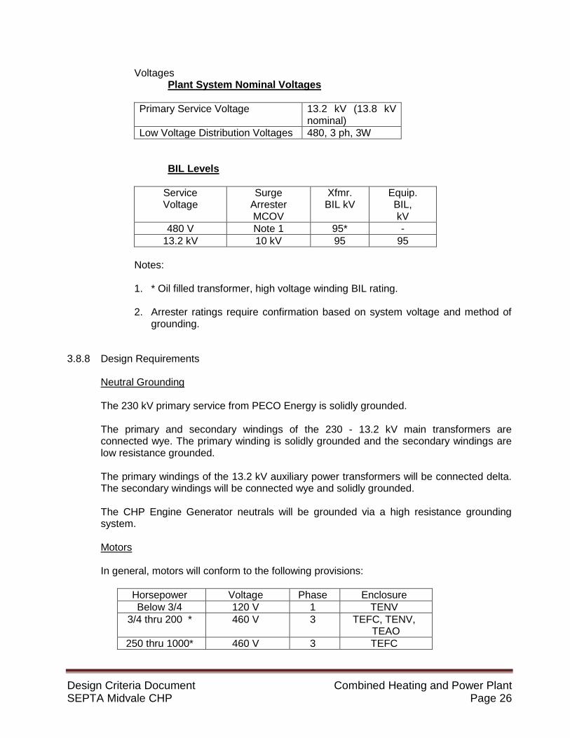
Voltages Plant System Nominal Voltages
Primary Service Voltage 13.2 kV (13.8 kV
nominal) Low Voltage Distribution Voltages 480, 3 ph, 3W
BIL Levels
Service Voltage
Surge Arrester MCOV
Xfmr. BIL kV
Equip. BIL, kV
480 V Note 1 95* - 13.2 kV 10 kV 95 95
Notes: 1. * Oil filled transformer, high voltage winding BIL rating. 2. Arrester ratings require confirmation based on system voltage and method of
grounding.
3.8.8 Design Requirements
Neutral Grounding
The 230 kV primary service from PECO Energy is solidly grounded. The primary and secondary windings of the 230 - 13.2 kV main transformers are connected wye. The primary winding is solidly grounded and the secondary windings are low resistance grounded. The primary windings of the 13.2 kV auxiliary power transformers will be connected delta. The secondary windings will be connected wye and solidly grounded. The CHP Engine Generator neutrals will be grounded via a high resistance grounding system. Motors
In general, motors will conform to the following provisions:
Horsepower Voltage Phase Enclosure Below 3/4 120 V 1 TENV
3/4 thru 200 * 460 V 3 TEFC, TENV, TEAO
250 thru 1000* 460 V 3 TEFC

Design Criteria Document Combined Heating and Power Plant SEPTA Midvale CHP Page 27
*Large motors such cooling tower fans, pumps, etc. will be controlled with VFDs. The type of motor enclosure will be selected to conform to the classification of the area in which the motor is to be installed. All motors will be premium efficiency type in accordance with NEMA and CEE recommendations. Type of enclosure and conditions at location of the motor will determine need for space heaters in motors. In each case, leads for the space heater will be brought into a junction box separate from the main junction box.
3.8.9 Design Criteria
Voltage Regulation
The allowable voltage drops will be based on the following: Connections between the 480 volt transformers and MCC will be short lengths of cable with minimal voltage drop. Transformer regulation will be considered for normal operating conditions and transformer taps will be set to obtain a specified bus voltage level under normal and light load conditions. Transformer impedance will be considered for voltage drop calculations during starting of motors and grouped motor re-acceleration. For motor starting voltage drop calculations, the minimum short circuit level at the specific bus will be used.
During Starting of Motors
In all cases involving motor starting, the voltage at the motor terminals must be sufficient to insure proper breakaway torque and acceleration of the motor. In general, the maximum allowable voltage drop through the system to the source busses during motor starting will not exceed the following values: On the bus supplying the secondary 10 percent distribution system (such as 13.2 kV). On the bus directly supplying a motor 10 percent (480 volt).
At motor (fed from MCC or Loadcenter) 20 percent

Design Criteria Document Combined Heating and Power Plant SEPTA Midvale CHP Page 28
During Normal Operation
The allowable voltage drop in the cables, based on full load, will not exceed the following values:
Primary distribution feeder cables (13.2 kV) 1 percent Secondary distribution feeder cables (480 volt)
2 percent
Motor, lighting transformer feeders 3 percent
Lighting branch circuits between the panel board and the most remote fixture or outlet
3 percent
Motor branch circuit 3 percent 3.8.10 Load Criteria
The following guidelines will be used as a basis for selecting the auxiliary transformer capacity based on the initial design load.
Initial Design Load
The initial design load will consist of the nameplate rating of all normally operating motors, the nameplate rating of motors designated as future on drawings and the mechanical equipment list, and the lighting, air conditioning, heating, and miscellaneous loads.
Motors designated as spare (one of a pair in the same service) will not be included in the initial design load when they are connected to the busses of a single-ended substation or MCC. Transformer Capacities
The initial design load connected to the low voltage transformers will not exceed 90 percent of the OA rating.
Short Circuit Levels
Maximum available short circuit duties will not exceed the interrupting and short circuit (momentary) rating of standard metal-clad/ metal-enclosed switchgear. Transformer impedance will be selected to meet this requirement.
Switchgear is not rated for maximum short circuit duty occurring during momentary paralleling of busses during bus transfers; therefore breakers will be interlocked to prevent paralleling.

Design Criteria Document Combined Heating and Power Plant SEPTA Midvale CHP Page 29
3.8.11 Protective Relaying
General All protective relaying for medium voltage switchgear will be based on microprocessor-based or solid-state relay. Protection features include multi-protective function capability and programmability (e.g., curve definition). Communications with the Plant Control System will be provided. ABB type FT-1 test switches will be provided for all current transformer and voltage transformer circuits. Medium Voltage Switchgear Protection
Main 13.2 kV switchgear (in existing plant) - Primary protection will be provided with an SEL 351 multifunction protective relay. This relay will include phase and grounding overcurrent and voltage functions, as well as other elements that may be required by PECO Energy for CHP anti-islanding protection.
13.2 kV CHP Switchgear
1. 13.2 kV feeders will have overcurrent (50/51) and ground fault protection (50GS). SEL 351A relays will be used.
Generator Protection
Protection of the gas engine generators will be provided by Beckwith M3425A Multifunction microprocessor relays with the following functions: 27, 32, 40, 46, 51V, 59, 81O, 81U, and 87. Beckwith M3425A relays will be used. Transformer Protection
Protection of the secondary unit substation transformer supplying the low voltage MCC will include as a minimum the following protection:
1. Transformer primary – 13.2 kV feeder breaker 50/51/50GS using an SEL 351A relays Motors
Low voltage combination motor starters or VFD’s will be used for low voltage motors.
3.8.12 DC Systems
Locations
Battery systems will be provided in each of the following areas: 1. 13.2 kV CHP switchgear (furnished by switchgear vendor)

Design Criteria Document Combined Heating and Power Plant SEPTA Midvale CHP Page 30
2. Engine generator batteries will be furnished by the vendor 3. UPS system battery
Voltages
Battery systems will be rated as follows:
Item Voltage Type 13.2 kV CHP switchgear 125 V Valve regulated CHP Engine Generator 24 V TBD UPS By Vendor By Vendor
Battery Types and Sizes Battery cells will be of lead calcium. Battery sizing will include compensation for end-of-life, correction for ambient temperature and design margin. The UPS battery will be sized to permit 15 minutes of operation. The switchgear battery will be sized to permit the initial tripping of circuit breakers and closing of main breakers after an 8-hour period.
Battery Chargers
Battery chargers will be sized to recharge a fully discharged battery to a full charge, in eight (8) hours while supplying 100 percent rated load.
3.8.13 Uninterruptible Power System - UPS CHP Control System UPS
The UPS system will consist of a rectifier/charger, inverter, static switch, maintenance bypass switch, alternate source transformer, and distribution panel.
3.8.14 Electrical Equipment
Space Allocation Minimum working clearance around electrical equipment will be in accordance with NEC Code Extra space will be reserved for operation and maintenance of all electrical components in accordance with the manufacturer's requirements. Extra space will be reserved for future expansion of medium and low voltage switchgear.

Design Criteria Document Combined Heating and Power Plant SEPTA Midvale CHP Page 31
3.8.15 Switchgear
General
Switchgear will consist of grouped assemblies of freestanding, vertical, dead-front steel structures containing power busses, draw-out power circuit breakers, load interrupter switches, necessary auxiliary control devices, instrument transformers, relays, meters, and control and meter switches. Switchgear assemblies will be installed in electrical equipment rooms. Switchgear will have NEMA 1 enclosures and will be provided with space heaters to prevent internal condensation. Each power circuit breaker will be capable of safely interrupting the maximum system short circuit current at the applied voltage level. In general, the new 13.2 kV switchgear will be connected to the existing station 13.2 kV system by cable. Medium Voltage Switchgear
13.2 kV CHP metal-clad type, switchgear (SG1301) will consist of draw-out type circuit breakers with electrically operated (DC), stored-energy type operating mechanism. Low Voltage Switchgear (MCC)
Motor Control Centers rated 600 volts and below will be metal-enclosed. MCC circuit breakers will be molded case type. Manually operated breakers tripped by remote devices will have shunt trip coils.
3.8.16 Power Transformers
The auxiliary service step-down transformer will be an outdoor, liquid immersed, 750 KVA self-cooled (ONAN-55oC) pad mounted transformer. The primary winding will be connected delta and the secondary windings will be wye-connected. The secondary neutral connection will be solidly grounded. The transformer shall be filled with Envirotemp FR3, FM Approved fire resistant dielectric fluid that meets or exceeds the requirements of the applicable ANSI and ASTM standards.
Transformer taps will be set so that, under no-load conditions, voltage on the secondary will not exceed 110 percent of the rated voltage.

Design Criteria Document Combined Heating and Power Plant SEPTA Midvale CHP Page 32
3.8.17 Motor Controllers
Controllers for Low Voltage Motors
Single Phase Motor Controllers In general, controllers for 120-volt single-phase motors will be manual motor starters except in special cases where magnetic contactor type starters are required. They will be fed from molded case circuit breakers located in a local power panel. Three Phase Motor Controllers Controllers for 3-phase low voltage motors will be the combination type consisting of a molded case air circuit breaker and a magnetic starter. Minimum starter size will be NEMA Size 1. As a minimum, each starter will have three (3) overload relays and a control power transformer with a fused 120-volt secondary. Motor controllers for indoor unclassified installations will be grouped, metal-enclosed, freestanding, dead-front, NEMA 1 type enclosure motor control centers with NEMA Class I Type B wiring. All starters NEMA size 1 through size 4 will be plug-in type.
3.8.18 Panelboards and Transformers
Panelboards
Branch circuit panelboards will be wall-mounted type. They will be 480volt, 3 phase, 3-wire, with a full capacity neutral. Bolt-on main and branch circuit breakers will be provided. Panelboards will have a maximum of 42 overcurrent devices per panel. The panelboard enclosure will be painted galvanized steel with knockouts and removable endwalls and a screwed-on front cover.
Transformers General purpose distribution transformers for 120 volt secondary power will be dry type, ventilated, two-winding, 3 phase, delta-wye connected with full capacity neutral, having two (2) full capacity 5% taps below normal voltage, floor-mounted and housed in a NEMA 1 enclosure. Transformer insulation system class will be 220 with an 115o C temperature rise above a 40o C ambient. Transformer sound levels will conform to ANSI and IEEE requirements. Transformer efficiency shall conform to the latest energy codes. Transformers will be UL listed.

Design Criteria Document Combined Heating and Power Plant SEPTA Midvale CHP Page 33
3.8.19 Grounding
CHP Plant Grounding System A loop grounding system with radial taps to equipment will be installed. Ground loop conductors will as a minimum be 2/0 AWG copper cable. Primary ground electrodes will be the steel foundation piles, copper-clad ground rods or concrete-enclosed reinforcing rod (that is, foundation rebar). One (1) anchor bolt at each building column will be connected to rebar with bolted connections. Every other steel building column will be connected with 2/0 AWG bare stranded copper cable directly to the main grounding loop. Steel structural members which are isolated from the ground because of building design will be connected to the nearest grounded structural member or directly to ground. The grounding of the engine generator units shall have all electrical equipment, including motor frames, equipment enclosures and junction boxes, permanently grounded to the skid base. The grounding shall also include two external grounding pads located on each end of skid base, equipped with bolted on NEMA 2-hole compression type lug for a 500 MCM ground wire. Connections to step down transformers, switchgear and unit substation ground busses, and motor control center ground busses will be 2/0 AWG, bare stranded copper cable. Each tap will be individually connected to the main ground loop or substation ground bus. Below grade grounding conductors will be buried a minimum of 2'- 0", and will be installed with slack, as required, between connections. Underground connections will be welded or mechanical type. Exposed grounding connections will be mechanical type. Electrical equipment operating above 600 V and enclosures of all power transformers, switchgear, and motor control equipment will be connected to the main ground loop with 2/0 AWG bare stranded copper cable. Other electrical equipment operating below 600 V will be grounded to the low voltage switchgear, MCC, or power panel ground bus by a grounding conductor run with the associated power feeders. In general, fences, pipe racks, metallic tanks, motors over 100 hp, and large skid mounted equipment will be connected (with 2/0 AWG bare stranded copper cable) to the main ground loop. Steel pipe racks will be grounded at every support column (on one side of rack). Single or parallel tray runs along a pipe rack will be grounded at intervals of 200’. Trays leaving a pipe rack, tray expansion fittings, and hinge splice plates will have bonding jumpers installed to ensure raceway ground continuity. Separate 2/0 AWG bare copper ground conductors will be run in cable trays to facilitate bonding. All motors larger than 100 hp will be grounded by connecting a 2/0 AWG bare stranded copper cable from main ground loop to the motor frame.
Metal tanks will be grounded by two terminals on each tank with 2/0 AWG bare stranded copper cable directly to the main ground loop. An insulated ground bus will be installed in the control room for instrument grounds. This bus will be isolated from power grounding conductors and building structures. It will be

Design Criteria Document Combined Heating and Power Plant SEPTA Midvale CHP Page 34
connected to a cluster of ground rods near the building and from there will be connected only at one point to the main ground loop.
Computer / Instrumentation
Appropriately sized ground bus and equipment connections will be installed for Computer/ Instrumentation grounding. All Computer/ Instrumentation grounding will be in accordance with the control system and instrumentation manufacturer’s requirements. Lightning Protection
Lightning protection will be provided for the building and cooling towers.
3.8.20 Lighting
Illumination Levels
Illumination levels will be in accordance with the IESNA Standards.
Design
All lighting associated with the project shall be LED.
Emergency lighting will consist of units with self-contained battery packs or circuit power from an emergency load panel.
3.8.21 Conduit and Conduit Fittings
Underground Raceways and Cables
In general, underground cables will be routed via concrete encased duct lines. Types EB or DB PVC conduit will be used. Underground cables installed under buildings will be in Schedule 40, rigid nonmetallic conduits extended at least 3 ft. outside the wall of the building.
The minimum cover requirements will conform to the requirements of the NEC. Rigid steel galvanized conduit will be used for all lateral runs from nonmetallic conduit duct banks with 45 degrees through 90 degrees and risers. All underground conduits will be encased in a concrete envelope providing a minimum outside encasement of 3 inches on all sides. The top of the concrete envelope will be a minimum of 18 inches below finished grade and will be colored red by sprinkling red oxide on the freshly poured concrete. The concrete envelope will be omitted within the confines of building foundations.

Design Criteria Document Combined Heating and Power Plant SEPTA Midvale CHP Page 35
Wherever the concrete encased conduit is subject to heavy traffic such as at roadway crossings, it will be structurally analyzed and reinforced with steel reinforcing bars as required. Conduit entering switchgear, motor control centers, and similar equipment through a concrete floor will terminate in couplings set flush with the finished floor, nippled, with a ground bushing, and sealed with a plastic sealing compound. Where conduit rises above grade, the encasing concrete will be extended a minimum of 3 inches above grade and be sloped for water runoff. Aboveground Conduit and Fittings
Aboveground conduit will be EMT (where permitted by the NEC), hot-dipped galvanized except in wet, or corrosive humid atmospheres where aluminum, plastic coated, or plastic conduit may be better suited. Aboveground conduit will be securely and adequately supported in accordance with the National Electrical Code. Aboveground conduit will be ¾ of an inch minimum, except that ½ of an inch conduit may be used for short runs to instruments, telephones, and outdoor control boards. Long radius elbows (factory bends) will be used for 1¼-inch (40 mm) conduit and larger. Field bends will be in accordance with the National Electrical Code. A maximum of three (3) 90o bends will be allowed in a conduit run between junction or pull boxes. During construction, temporary openings in the conduit system will be plugged or capped to prevent entrance of moisture and foreign matter.
Conduit between pipe supports and equipment will not be supported from piping. Conduit fittings will be selected in accordance with the National Electrical Code. Where splices are required, boxes having sufficient volume to comply with the National Electrical Code will be used. Expansion fittings will be installed in long straight, horizontal, and vertical conduit runs Vented drains or drain seals will be provided at the low point of long, vertical, or horizontal runs of conduit where condensation could accumulate, and in outdoor areas where conduit enters boxes or enclosures from above. Connections to equipment requiring removal from service or subjected to vibration or movement will be made with flexible conduit. Liquid-tight flexible metal conduit and approved fittings will be used for outdoor equipment in unclassified and Class I, Division 2 locations. EMT (Electrical Metallic Tubing) may be used in indoor locations where the conduit will not be subject to severe physical damage and where hazardous atmospheres do not exist.

Design Criteria Document Combined Heating and Power Plant SEPTA Midvale CHP Page 36
Control stations installed in classified areas will be factory-sealed type. 3.8.22 Cable Trays
Overhead cable tray will be aluminum or hot-dipped galvanized steel. In corrosive areas, fiberglass or an equivalent material will be used. The tray types may be vertical or horizontal, of ladder, trough, or solid bottom design, with adequate drain holes. Use of cable tray will be limited to Class I, Division 2 and unclassified areas. Straight sections and fittings will have the provision and standard parts for covers when required for a specific installation. Tray straight sections will be 12’ and 24’ in length. Cable tray fill will be in accordance with cable types and methods prescribed in the National Electrical Code. Fabrication specifications and fittings support will be in accordance with NEMA VE-1 for cable tray. Tray fittings will be identical to straight sections in materials, rung spacing, and strength. Tray fittings will have adequate radii for the cable to be installed. Cable tray connectors will be rigid, straight, adjustable, or expansion type. Standard accessories used to supplement straight sections and fittings will be dropouts, conduit adapters, dead-ends, non-combustible dividers, cable clips, tray-to-box connectors, and hold-down hardware. Each cable tray system will be connected to ground at a minimum of two points. Ground connection will be provided per each 200’ run of each cable tray as a minimum. The maximum straight section length of cable tray, when fully loaded in accordance with the manufacturer's recommendations, will not deflect more than 2” and will have a minimum safety factor of 1.5.
3.8.23 Power and Control Wiring
Cables for Service Above 600 Volts Medium voltage power distribution cables will be 15 kV grade, Type MV-105, single copper conductors, Ethylene -propylene rubber (EPR) insulation (133%), flame-retardant and moisture-resistant PVC jacket and copper tape shielded. The current carrying capacity and short circuit withstand capability of cables will be in accordance with NEC and applicable ICEA tables and recommendations. Power conductors will be installed in a separate conduit from control or instrument conductors.

Design Criteria Document Combined Heating and Power Plant SEPTA Midvale CHP Page 37
Cables for Service 600 Volts and Below
Low voltage power and control cables will be 600-volt grade, Type RHH/RHW or XHHW (single or three conductor), ethylene propylene (EP), VW-1 insulation, or Type TC with overall flame-retardant and moisture-resistant jacket (multi-conductor power and control cables). For high temperature locations, wire with suitable insulation will be used where required. Instrumentation cables will be 300-volt grade, Type PLTC, single or multiple twisted-shielded pairs, overall shielded (for multi-pair), flame retardant PVC insulation, Mylar tape shields (individual pairs and overall shield), and flame-retardant and moisture-resistant jacket. Thermocouple extension wire will be 300-volt grade, single or multi-pair with construction similar to the instrumentation cables with Type E (Iron constantan) conductors, unless otherwise noted. Fiber optic, twisted pair or coaxial cables will be provided for the PAC and fire system equipment as required. Minimum conductor sizes will be # 12 AWG for miscellaneous power circuits, and # 14 AWG for control circuits. In general, wire and cables will be sized in accordance with NEC. Multi-conductor control cables will be color coded or numbered in accordance with NEMA WC-5. The manufacturer's recommendations will be used for the minimum bending radii of cables and wires. Cable for installation in cable trays will be approved for tray installation. Cables for variable speed drives will meet the drive manufacturer’s requirements.
Wiring Levels/Classes and Separation
All electrical wiring will be categorized by level in accordance with the requirements of IEEE 518.
Cable/raceway separation by levels will be in accordance with the requirements of IEEE 518.
3.8.24 Control Systems Instrumentation
Materials
Detail specifications will be issued for all multi-conductor instrument wire and cable.
Design Criteria Document Combined Heating and Power Plant SEPTA Midvale CHP Page 38
Enclosures for field junction boxes will be NEMA-12 for indoor applications and NEMA-4 for outdoor applications, with hinged removable doors and sub-panels for terminal strip mounting. Terminal strips for instrument wiring will consist of 300 volt, medium duty tubular clamp polypropylene terminal blocks mounted on slide-rail strips.
Installation
Installation of all equipment shall follow the equipment manufacturers’ recommendations. Wiring for field instrument devices will be accomplished by installing individually shielded twisted pairs or triads for milliamp, DC, or millivolt signals in from field junction boxes. Wiring from local field boxes to control room will be multiple pair or triad cables with an overall shield for DC and milliamp signals routed in conduit or cable tray. Cables for millivolt signals will have both individual pair shields and overall shields. Wiring for AC signals will be multi-conductor cables routed in conduit or cable tray. Home Run instrument cables will contain 20 % spare pairs, triads, and conductors; and they will be terminated and tagged at both field junction box and control room ends. Individual shield drain wires for thermocouple pairs will be grounded at the instrument head only. Individual shield drain wires for milliamp, DC pairs, and triads will be cut and taped at the instrument head. Shield drain wires at field junction boxes will be jumpered and connected to the overall shield drain wire in the Home Run cable for milliamp and DC Signals. For millivolt signals, individual pair shields in multiple pair cables will be connected to corresponding single pair shields; overall shield will be grounded at the control room. Shield wires will be insulated from ground at the junction box. Note: Shield for field-powered devices terminate in the field. Individual shield drain wire for multi-pair thermocouple cables will be cut and taped at the control room. Overall shield drain wire for all other multi-pair cables will be grounded at the control room. Tagging of all wires or pairs will be on both sides of each termination point. Individual junction box and conduit systems will be provided for millivolt, AC, and milliamp / DC instrument signal levels.
Separation of circuits will be in accordance with the recommendations of IEEE 518 unless otherwise required by the PAC vendor.
AB. COMMUNICATIONS (VOICE AND DATA)
A Page party/ public address system is not included. The public telephone system will be by Others.

Design Criteria Document Combined Heating and Power Plant SEPTA Midvale CHP Page 39
Voice and data circuits for the 13.2 kV switchgear and SCADA equipment will be required by PECO and requires confirmation. AC. SECURITY - (N.I.C.)
Surveillance Cameras
As deemed necessary by the CHP owner.
Intrusion detection and access controls
As deemed necessary by the CHP owner.
AD. HEAT TRACING Process
Electric heat tracing will be provided if required.
Freeze Protection
Freeze protection will be provided if required.
3.9 INSTRUMENTATION AND CONTROLS SYSTEM
The Plant Control System (PCS) shall be a Programmable Automation Controller (PAC) based system with an Allen Bradley ControlLogix microprocessor and shall utilize a distributed architecture, incorporating single process controller and distributed remote I/O. Field instruments shall have SMART electronics and utilize HART protocol whenever available. Alternately instrumentation and control valves may be provided with bus type technologies instead of traditional 4-20 mA signals. The Plant Control System (PCS) shall consist of a network of ControlLogix PAC, I/O panels, and an operator’s human-machine interface package (HMI) that will provide operators with the ability to monitor and operate the CHP plant from a central location. Included in the PCS are operator stations, engineer workstation, historian data collection, operator interface displays with web server, communication interface, and report/graphic printer. The HMI package utilized by the PCS shall include PC based operator interfaces, complete with a graphical display and report generation packages. The HMI package shall be capable of current and historical trending as well as performing historical data storage in a retrievable format. The CHP plant’s control system shall be restricted to the CHP plant.

Design Criteria Document Combined Heating and Power Plant SEPTA Midvale CHP Page 40
Instrument and control systems design shall be engineered to provide for the safe and efficient start-up, operation, and emergency shutdown of the CHP facility. The PCS shall sequence all major pieces of equipment, constantly balance system operation and optimize equipment operation to reduce energy usage. As the load increases or decreases, the system shall adjust plant operating parameters to maintain the optimum pressure and water temperature differential to achieve the highest level of efficiency.
3.9.1 System Integration Balance of Plant (BOP) PAC processor and I/O shall reside in the CHP plant. Major pieces of mechanical equipment shall be supplied with onboard PAC based controllers for automatic control of this equipment. Control of BOP equipment, not supplied with an onboard controller, shall be by the PCS. The PCS communication network for processor data shall be via an Ethernet/IP. Communications to the HMI will utilize an Ethernet star topology. This communication network shall allow PCS devices and equipment packaged controllers to function as an integrated unit. The network shall also connect to the operator’s interface/engineer workstation located in the control room.
The integrated Plant Control System (PCS) design criteria are:
1. BOP PAC processor and remote I/O enclosures shall be located throughout the CHP
plant as needed. 2. Plant equipment shall be operated from the operator’s console located in the control
room. Indication of operating parameters and alarms shall be provided for equipment and processes in the operator’s console.
3. Interaction between the equipment onboard controllers and the PCS processors shall be totally transparent to the operator. Critical control points, system interlock, and other safety related signals shall be hardwired to the PCS.
4. System architecture shall be such that failure of any single components will not cause a total plant shutdown. Hardwiring of non-critical signals will be avoided.
5. The PCS shall be furnished by an authorized Rockwell Automation Solution Provider with demonstrated experience in the design and deployment of similar CHP automation packages. Local suppliers include but are not limited to: Applied Control Engineering, Inc, Newark, DE; Automated Control Concepts, Inc., Neptune, NJ; and Thermo Systems LLC, East Windsor, NJ.
The following automation design documents shall be part of the integrated PCS engineering package:
1. Detail Design Specification (DDS) – The DDS shall define all PAC node
programming and sequence of operation. In addition the DDS shall define all of the HMI programming requirements including alarm summaries, historical trend summaries, graphic screen listings and all information required for the proper configuration and set up of the PCS.
2. Hardware Design Specification (HDS) – The HDS shall define all of the new BOP instruments & controls that will make up the PCS. This includes field sensors, field controllers, panels for local/remote control and indication, power supplies, I/O

Design Criteria Document Combined Heating and Power Plant SEPTA Midvale CHP Page 41
modules, third party interfaces, field wiring terminations, power distribution wiring, and operating and application software packages.
3. Control System Architecture –Control system architecture drawing depicting all PAC nodes and remote I/O nodes and define all communications risers, protocols, and controller addresses.
4. PAC Panel Production Drawings – Full-scale panel production drawings for each PAC node, remote I/O node, hub panels, fiber panels, and equipment interface panels.
5. PAC System Block Diagrams - Single line riser diagrams for each PAC panel and remote I/O node. These single line risers shall detail wire type and conductor quantities required for each field device and I/O point.
The integrated PCS execution, installation, and startup criteria are:
1. PCS Control Panels – All PAC nodes, remote I/O panels, and communication
interface panels will be tested and fabricated as depicted on the control system architecture drawing and PAC panel production drawings.
2. BOP Instrumentation and System Installation – All PCS instrument and equipment as listed in the Instrument Index Control System Scope of Supply shall be furnished by the PCS supplier with certificates and calibration and factory tested prior to installation. A turnkey installation including mounting all instruments, furnishing, and installing all pneumatic tubing for instrumentation (including all communication cabling and pneumatic signal lines) shall be provided by the PCS supplier.
3. Vendor Packaged Instrumentation Installation – All vendor supplied instrumentation that is shipped loose and not directly connected to the system shall be installed, wired, and tubed by the PCS contractor.
4. PAC Program Development - All PAC programs for the PCS will be developed by the PCS supplier in accordance with the approved Detailed Design Specification. PAC programming shall be completed using the latest version of RSLogix5000. A consistent and detailed naming convention and comment structure shall be incorporated in accordance with the PCS Supplier PAC Programming Standards.
5. PCS Software Development – All PCS PAC and Human Machine Interface (HMI) software and hardware for the PCS shall be furnished by the PCS supplier.
6. HMI Application Development – All HMI applications including HMI graphics, alarms, historical trends, reports, and security management shall be developed by the PCS supplier in accordance with the approved Detailed Design Specification.
7. Hardware Factory Acceptance Test (HFAT) – Testing document detailing the test procedures to be performed on each PCS control panel and its components shall be developed and executed by the PCS supplier.
8. Software Factory Acceptance Test (SFAT) – Testing document detailing the test procedures to be performed for each PCS PAC programming component including sequence of operation shall be developed and executed by the PCS supplier.
9. Site Acceptance Test (SAT) – Testing document detailing the on-site tests to verify the proper functionality of the BOP PAC components and subsystems shall be developed and executed by the PCS supplier.
10. Application Installation and Testing – All PCS programs shall be programmed and tested on site by the PCS supplier. The PCS supplier shall commission all communication links to the PCS.
11. Field Loop Checks – The PCS supplier shall execute documented field loop checks for all I/O connected to the PCS.

Design Criteria Document Combined Heating and Power Plant SEPTA Midvale CHP Page 42
12. PCS Start Up and Commissioning – The PCS supplier shall start up and commission the entire PCS, including coordination and commissioning support of vendor packaged automation equipment that connects to the PCS network.
13. Training – The PCS supplier shall develop a customized users’ manual that is project specific and conduct onsite training for the owner’s personnel.
14. Documentation and Manuals – The PCS supplier shall furnish operation and maintenance manuals for all of the PCS equipment.
3.9.2 PCS Hardware Overview
Plant operators and supervisors shall be able to easily determine operations status and perform all major control functions utilizing the PCS HMI package. The CHP Plant PAC control system will consist of balance of plant PAC control panel for the CHP plant and HMI communicating via the CHP plant communication network.
3.9.2.1 PCS-Programmable Automation Controller (PAC) Control Panel
PAC processor and ancillary supporting hardware shall be industrially hardened microprocessor based controller suitable for use in operating condition of up to 140 °F. All field run cables from all the field devices, marshalling cabinets, engine control panels shall be terminated in the PAC controller and/or remote I/O panels as required. PAC processors shall be true multi-tasking, multi-user, real-time digital control processors consisting of modular hardware with plug-in enclosed processors, communication controllers, power supplies and input/output point modules. PAC system hardware shall be supplied as follows:
A. One CHP PAC control panel, tagged PCS-100, with control processors, redundant power supplies, I/O racks and industrially hardened, managed Ethernet switches. A minimum of two Ethernet switches shall be provided. The Ethernet switches shall be modular and be provided with minimum of 8 RJ-45 ports and 2 fiber-optic ports. Electronics and field terminations shall be installed in separate compartments.
B. One wall mounted Ethernet communications panel, tagged NDE-200, for
installation near the VFD’s. The panel will be supplied with an industrially hardened, managed 8-port Ethernet switch and an unswitched power outlet strip. The panel shall have expansion space for one additional 8-port Ethernet switch.
C. One server cabinet, tagged NDE-100, to house the following: Web HMI server,
Plant Historian server, Ethernet router/firewall and 24-port Ethernet switch. D. Provide hardware as required for remote Internet access/support of the BOP
control system. As a minimum, the contractor shall provide a hardware router/firewall with VPN capabilities. The Owner will provide the Internet connection point. Any Ethernet hardware shall conform to SEPTA IT Department requirements.
E. The Balance of Plant control processors shall be Allen-Bradley ControlLogix
PACs sized to support both hard-wired and serially communicated I/O and process logic. Processor program scan time shall not exceed 100 msec.

Design Criteria Document Combined Heating and Power Plant SEPTA Midvale CHP Page 43
Communication links to I/O racks shall be ControlNet, Ethernet/IP (physically separated from any enterprise network) or Ethernet Device Level Ring (DLR) topology. PAC processor will have the capability of performing continuous analog control routines, discrete signal processing and real-time sequencing of equipment. Each PAC will allow manual override of equipment controls including start/stop and analog control functions.
F. The system shall be designed with 20 percent spare wired I/O points of each
type, in each panel to support future expansion capacity. All spare I/O shall be wired to terminal blocks. Each enclosure will also be provided with 20% spare space for the addition of future modules. As a minimum, the following hardwired I/O shall be provided:
• Analog Input, 4-20 mA, 32 each • Analog Output, 4-20 mA, 16 each • Digital Input, 24 VDC or 120 VAC, 64 each • Digital Output, Dry Contact, 32 each, 80% with interposing relays
G. Communications between the BOP control system and skid based packages
will be provided where available. For Allen Bradley PAC/PLC, acceptable communications protocols are Ethernet/IP or ControlNet; non-Allen Bradley controls interfaces are Modbus TCP/IP and DNP3.0. Response time between the BOP control system and these their party devices shall be 1 second or less for control signals and 5 seconds or less for data monitoring points. At a minimum, the equipment listed below will require a communication interface to the Balance of Plant control system: • Engine Generator Set #1 (100 soft I/O point minimum) • Engine Generator Set #2 (100 soft I/O point minimum) • SCR #1 System (25 soft I/O point minimum • SCR #2 System (25 soft I/O point minimum) • Electrical Switchgear System (50 soft I/O Points minimum)
H. Equipment and skid based systems not equipped with their own automatic
control systems shall be monitored and controlled from the Balance of Plant PAC system.
I. Fiber optic cabling shall be provided for all communications cabling physically
run between two buildings unless otherwise indicated on the system architecture diagram or between areas with high potential for EMF interference. The I&C Contractor is responsible for the supply of network switches. The electrical contractor is responsible for supply and installation of all fiber optic and copper cables. Multi-mode fiber cable shall be used unless distances require the use of single-mode cable. The electrical contractor shall provide the Owner and the I&C Contractor with test reports for all fiber cable installed.
J. All communication networks shall be designed, installed and tested to the
manufacturer’s physical media specifications and guidelines.
Design Criteria Document Combined Heating and Power Plant SEPTA Midvale CHP Page 44
K. Indoor control panels, mounted in dry areas presenting no exposure potential for water ingress, shall have NEMA ratings of not less than NEMA 12. In indoor areas where the exposure to water is possible, the minimum NEMA rating shall be NEMA 4. All enclosures installed outdoors shall not be rated less than NEMA 4X.
L. All power supplies shall be redundant, with featuring seamless transfer in the
event of power supply failure. Each power supply will be provided with an alarm output.
M. The control system shall be powered from two (2) separate sources. One (1)
source shall be 120 VAC from a plant Uninterruptible Power Supply (UPS). The second source shall be conditioned 120 VAC.
N. Analog modules shall be standard, isolated 4-20 mA signal type. Digital input
modules shall be either 24 VDC or 120 VAC signal type. Digital output modules shall be AC, DC or dry contact outputs with voltage/current ratings as needed to meet operating parameters. General purpose control relays shall be used where end device amperage exceeds module capabilities.
O. The I&C Contractor is responsible for the supply of network switches and
installation in control system and network distribution enclosures. Switches shall be suitable for industrial Ethernet and switches provided in cabinets NDE-100, NDE-200 and PCS-100 shall be supplied with at least 2 high speed (Gigabyte) ports and dedicated trouble contact outputs.
P. Category 5e cabling utilizing RJ-45 connectors will be used for all interior
Ethernet communications cabling. See the architecture diagram for connection details. Shielded cable shall be required if the manufacturer’s separation requirements for unshielded cable cannot be met. The I&C Contractor shall provide all pre-fabricated patch cable for use in the network distribution enclosures, between the Ethernet switches and the HMI PCs and the engineering work station. The electrical contractor is responsible for supply, installation and testing of all field routed cables. The electrical contractor shall provide the Owner and the I&C Contractor with test reports for all network cable installed.
Q. Internal enclosure wiring shall meet the following criteria:
• Field wiring shall not be terminated on I/O card mounted terminal blocks. Separate marshalling terminal blocks shall be provided, installed in separate control cabinet termination compartment for termination of field cables. The Supplier will wire from the I/O card to the marshalling terminal blocks at the factory. Spare I/O will be wired out to these terminal blocks. Space shall be provided for the addition of future terminal blocks, in sufficient quantity to accommodate the spare space requirements of this specification.
• Each wire internal to panels shall be uniquely identified with permanent wire markers. Wire numbers on labels must match wire numbers shown on

Design Criteria Document Combined Heating and Power Plant SEPTA Midvale CHP Page 45
system layout, cabinet assembly, and I/O wiring diagrams. Field routed cable numbers shall be clearly readable at the terminal location.
• Fused circuits shall have LED type blown fuse indication. • Splicing of wiring is prohibited. • No more than two wires shall be connected at each terminal point. In areas
subject to above normal levels of vibration, wire ferrules will be used on wire ends.
• Wiring shall be neatly arranged and clamped securely to panels to prevent movement and breakage. Wiring clamps and supports at hinge transition points shall be properly sized to prevent chafing of insulation when the panel door is opened and closed.
• Cable entry into the cabinets shall be through the top and/or bottom. Cable supports shall be provided in each cabinet. Cables shall not block access to any cabinet hardware for equipment inspection, maintenance or removal and replacement.
• Power distribution for 4-wire instrumentation and externally powered control valves shall be provided in the control system enclosure. Each feeder circuit shall have fused disconnect type terminals with an overall main circuit breaker. Blow fuse indication shall be provided. At least 25% spare circuits of each voltage level shall be provided.
R. All control panels shall be UL or CSA listed.
3.9.2.2 PCS-Operator Interface (HMI)
A. HMI software package (Rockwell FactoryTalk Site Edition Standalone or other
equivalent third party package) shall be provided for the display of graphic interface screens including process graphics, alarm summaries, log reports trending, web server and historical data storage. Data shall be automatically stored on the terminal hard disk in a file format that is exportable to spreadsheet and database programs. Data shall be archived to magnetic tape or DVD when initiated by an operator. HMI hardware provided shall be the latest technology currently available, including at a minimum the following:
B. Two (2) Single Screen Operator Workstations will be supplied and configured to
meet the following minimum specifications: • One (1) 24” flat panel LCD type color monitors, with 1600 by 1200 resolution,
DVI input, and includes integrated audio speakers. • 100 Base-T Ethernet connectivity • 1 TByte hard drive • Dual core Intel processor, 2.66 GHz or higher • GB RAM, expandable • Internal DVD +/- RW-Drive • Qwerty Keyboard and optical mouse • Sound card for audio output to LCD display speakers • Windows 7 Professional Operating System • Microsoft Office Small Business 2010 • Rockwell Factory Talk Site Edition Station (Standalone w/250 display license)
& RSLinx Software or approved equal • Norton Antivirus 2012 or equal

Design Criteria Document Combined Heating and Power Plant SEPTA Midvale CHP Page 46
C. One (1) Process Historian/Engineering Work Station will be supplied and
configured to meet the following minimum specifications: • One (1) 24” flat panel LCD type color monitor, with 1600 by 1200 resolution,
and DVI input • 100 Base-T Ethernet connectivity • 1 TB hard drive • Dual core Intel processor, i5 2.66 GHz or higher • 8 GB RAM, expandable • Internal DVD +/- RW-Drive • Qwerty Keyboard and optical mouse • Windows 7 Professional Operating System • Microsoft Office Small Business 2010 • Rockwell Factory Talk Site Edition HMI Development Software or approved
equal • Rockwell RSLogix 5000 PLC Programming Software w/ RSLinx
communications software or approved equal • Rockwell Factory Talk Site Edition Historian Sever Software, licensed for
1000 points, or approved equal • Norton Antivirus 2012 or equal
D. One (1) Process Historian/HMI Web Server will be supplied and configured to
meet the following minimum specifications: • One rack mounted PC with integrated qwerty keyboard, pointing device and
flat panel LCD type color monitor • 100 Base-T Ethernet connectivity • 1 TB hard drive • Dual core Intel processor, i5 2.66 GHz or higher • 8 GB RAM, expandable • Internal DVD +/- RW-Drive • Windows 7 Professional Operating System • Microsoft Office Small Business 2010 • Rockwell Factory Talk VantagePoint Server/Client Software, licensed for 5
users or approved equal • Rockwell Factory Talk Site Edition Historian Sever Software, licensed for
1000 points, or approved equal • Norton Antivirus 2012 or equal
E. One (1) HP LaserJet CP-5225 or approved equal will be provided for report
generation and graphics printing.
F. Graphic screens shall be provided to allow for full monitoring and control of all plant systems, allowing rapid diagnosis and correction of process upsets. Screen call up time shall be 3 seconds or less. Screen data update time shall be 1 second or less. As a minimum, graphic displays of the following types will be provided on both the local and web based graphics servers:
• A minimum of 25 Process displays based on P&IDs and one-lines (Pop up
type displays shall not be included in this total)

Design Criteria Document Combined Heating and Power Plant SEPTA Midvale CHP Page 47
• One Alarm summary Screen, separate from the built in graphic alarm summary area
• Set point screens for each controller or operator adjustable algorithm • Auto-sequence startup displays as needed for operation of the plant • Navigation menus as required to provide easy navigation between screens • Real-time and historical trends for critical plant operating parameters. As a
minimum, all analog data (soft and hardwired I/O and calculated points) shall be trended.
• Duplication of vendor equipment screens for all pieces of equipment including engine generators, SCR, compressors and all other rotating equipment.
• Graphic select shortcut keys on each screen
G. The data historian shall, as a minimum, collect all analog data (soft and hardwired I/O and calculated points). Data collection interval shall be a every 10 minutes unless otherwise specified.
H. Reports: Printed custom reports shall be produced on a shift, weekly, and monthly
basis to show high, low, and average values of major process parameters. Totalized energy consumption reports shall be produced daily. On-line energy use reports shall be produced at 15-minute intervals. On-line energy usage reports shall be printable on-demand. The PCS shall be capable to email reports directly to the required recipients.
I. Alarms: Alarms shall be annunciated at the operator interface when a parameter
goes outside of predefined ranges. Each hardware and software point shall have individual alarm parameters. Record all alarms to hard disk with the following information: • Time and date • Alarm message in English of at least 36 characters • Time and date of acknowledgement and/or clearing the alarm • Time and date of alarms which return to normal on their own
3.9.3 CHP Plant Sub-Systems Controls Interfaces
Vendor supplied equipment mounted panels will be utilized for the engine generators and other miscellaneous systems. PCS interface to these panels will be by Ethernet/IP wherever possible. Modbus/TCP or DNP 3.0 communication protocols will be the alternate interface option. Major plant systems to be controlled and monitored are:
3.9.3.1 Engine Generator
The control system shall also provide monitoring, control, status, alarm and data acquisition and storage for each of the two engine generator sets. The generator manufacturer shall supply and configure a PAC. Communications to the PCS will be via an Ethernet I/P connection and selected data in thes generator PAC will be available in both the local engine HMI as well as the remote PCS HMI.

Design Criteria Document Combined Heating and Power Plant SEPTA Midvale CHP Page 48
3.9.3.2 SCR Systems The control system shall also provide monitoring, control, status, alarm and data acquisition and storage for the two SCR systems. The SCR manufacturer shall supply and configure a PAC with communications to the PCS via an Ethernet I/P. Selected data in this SCR PAC will be available in the local HMI as well as the remote PCS HMI.
3.9.3.3 Engine Radiator System Constant speed water pumping shall be provided to maintain proper flow through the radiators with hot water heat exchanger (HX-01) flow/temperature control provided by a 3-way control valve. The jacket and auxiliary cooling water temperatures will be varied to through the control of the radiator fans. The PCS will enable the radiator fan controller prior to an engine start. Individual components (pumps and radiator fans) shall be automatically started and stopped as required to meet engine generators’ cooling requirements. Each piece of equipment lead/lag status shall be rotated weekly from the local controller according to accumulated run time.
3.9.3.4 Water Treatment Systems
Water treatment systems for the hot water and cooling water in the CHP plant will be provided by a water treatment system supplier. It will be designed to prevent hot water and cooling system corrosion and scale and inhibit biological growth. The water treatment systems in the CHP plant shall be a stand-alone controller and interface with the PCS to transmit status and process data such as conductivity and pH to the PCS system. CHP water treatment systems include make-up water softener and chemical feed skids.
3.9.3.5 Electrical Generation and Distribution System
The PCS shall also provide monitoring, status, alarm and data acquisition and storage for the electrical system at the CHP plant including the 13,200 V electrical systems and the 13.2 kV feeders. The electrical system relays and metering modules shall be connected to the PCS over a Modbus TCP serial link. If available, the PCS will read PECO metering kilowatt-hour pulse signal from the 13.2 kV service point. This signal will be repeated by the PECO meters for use by the PCS.
3.9.3.6 Fuel Delivery System
The PCS shall monitor fuel gas consumption, fuel gas compressor skid operation, and monitor the emergency shutoff valves for the gas supply to engine generator and other equipment.
3.9.3.7 Compressed Air System

Design Criteria Document Combined Heating and Power Plant SEPTA Midvale CHP Page 49
The PCS shall monitor the compressed air system (including dryers) and alarm on loss of compressed air to the CHP.
3.9.3.8 Building Ventilation Fan Control Variable speed ventilation fan control shall be provided to maintain proper internal temperature and engine combustion air flow. Minimum fan speed shall be set in the VFD to meet the engine minimum combustion air flow requirements. Fan speed shall increase to maintain interior temperature at 85°F (adjustable). The PCS will start the ventilation fans prior to an engine start and keep the fans running for 30 minutes after the engines have been stopped, under temperature control.
3.9.3.9 Continuous Emissions Monitoring System (CEMS) If required by the Pennsylvania DEP, a software based CEMS shall be furnished as a stand-alone system. The PCS shall interface via Ethernet protocols to integrate CEMS data to the PCS as required.
3.9.4 Miscellaneous Equipment Status All motors shall have status feedback. VFD drives will be connected to the PCS and data such as drive status and speed will be brought into the PCS. Full control and monitoring of VFDs shall be supplied using an Ethernet communications interface wherever possible.
If a constant speed motor does not prove operational within 15 seconds of command (adjustable), the motor shall be classified as “Failed” in the controller, shall be removed from the Lead/Lag list and an alarm sent to the central terminal. If a “Failed” motor status shows operation for 5 seconds (adjustable) then the motor shall be added back to the Lead/Lag list and shall be available for use. Alternately, the operator can clear the “Failed” point from the central terminal. If a VFD is classified as “Failed”, the VFD shall be stopped and an alarm shall be sent to the central terminal. When the VFD shows the failure is clear, the VFD shall be enabled and started if required. While the VFD is failed, the closest combination of constant speed motors shall be started to meet the load. For systems with redundant components, in the case of a failed primary mover, the secondary mover will be automatically started and the start command of the primary mover reset to prevent inadvertent starts. If on/off type control valve does not prove correct position within 15 seconds of command (adjustable), the valve shall be classified as “Failed” in the controller. The operator shall be able to clear the “Failed” point from the operator’s console.

Design Criteria Document Combined Heating and Power Plant SEPTA Midvale CHP Page 50
3.9.5 Instrumentation Local indicating devices, pressure gauges, thermometers, etc., shall be furnished for local monitoring of selected plant parameters. Electronic Smart type transmitters for differential pressure, gauge pressure, level and temperature will be provided for input into the PCS. All transmitters will have local readout in engineering units. Transmitter outputs shall be 4—20 mA. All instrumentation shall be industrial grade equipment. As an alternate, the developer may use field bus type instrumentation such as Foundation Field Bus or Profibus technologies. Requirements for specific type of instruments are as follows:
3.9.5.1 Pressure gauges: Direct-mounting, dial-type pressure gauges, complying with ASME B40.100, 4.5” dial.
3.9.5.2 Temperature gauge: Direct-mounting, bimetallic-actuated dial complying with ASME
B40.3, 5-inch diameter, bimetal coil element. 3.9.5.3Temperature Sensor: Direct-mounting, industrial temperature sensor with either
thermocouple RTD type elements and local indicator, Aluminum NEMA 4X connection head, ‘hockey puck’ transmitter with isolated 4-20 mA output, loop powered. Accuracy - ±0.2% of span.
3.9.5.4 Pressure transmitter: Industrial grade smart-type pressure or differential pressure
transmitter, 4-20 mA output with HART protocol. Accuracy: ±0.25 percent of calibrated span, NEMA 4x aluminum housing, stainless steel wetted components, ½” NPT process connection, local LCD display, stainless steel 2 or 3-valve manifold, stainless steel tag.
3.9.5.5 Flow Meters: Industrial grade smart-type flow meter with transmitter, 4-20 mA output with
HART protocol. Accuracy: ±0. 50 percent of calibrated span, NEMA 4X aluminum housing, stainless steel wetted components, local LCD display, and stainless steel manifold if applicable, stainless steel tag. Meters may be differential pressure, magnetic, thermal dispersion, vortex, swirl, or ultrasonic types. Manufacturer’s straight run requirements must be met.
3.9.5.6 Level Transmitters: Industrial grade smart-type level transmitter, 4-20 mA output with
HART protocol. Accuracy: ±0. 50 percent of calibrated span, NEMA 4X aluminum housing, stainless steel wetted components, local LCD display, and stainless steel tag. Meters may be differential pressure, radar, capacitance or ultrasonic types. Manufacturer’s installation requirements must be met.
3.9.5.7 Process switches: Piston actuated pressure/differential pressure/temperature switch, dry
contact, SPDT, rated 24 VDC at 0.5 amps and 120 VAC at 0.25 amp, adjustable set point, factory set, fixed dead band. Provide with manifold or thermowell as applicable.
3.9.5.8 Level switches: Ball float actuated switch element, dry contact, SPDT, rated 24 VDC at 0.5
amps and 120 VAC at 0.25 amp. Ultrasonic or capacitance type switch elements may also be used.

Design Criteria Document Combined Heating and Power Plant SEPTA Midvale CHP Page 51
3.10 COMPRESSED AIR SYSTEM
3.10.1 Instrument Air System
Two (2), 100%-capacity air compressors shall be provided to supply instrument and service air to pneumatic actuators and plant air. The compressed air system shall include an aftercooler, a moisture separator, air dryers (refrigerant for indoor air, dessicant for outdoor air), a receiver, a prefilter, an afterfilter, instrumentation and controls. The air dryer shall be a refrigerant type dryer for all indoor control air applications. For outdoor applications, a small dual-column, heatless, desiccant, automatically regenerating type shall be used. Controls shall automatically alternate the dessicant dryer trains between their operating and regenerating cycles. The receiver shall be designed to meet the ASME Unfired Pressure Vessel Code. A pressure relief valve and an automatic condensate drain shall be included with the receiver. The afterfilter shall be equipped with a differential pressure gauge to indicate when filter replacement is required.
3.10.2 Service Air System The service air system shall tap off of the compressed air system after the receiver and before the instrument air dryer. Service air shall be available for service air stations throughout the CHP plant for pneumatic tools and other plant maintenance purposes.
3.11 FIRE PROTECTION 3.11.1 General Conditions
Plastic building insulation materials that produce hazardous vapors on combustion or heat or flame shall not be used. Fire protection equipment shall be installed to conform to standards of the National Fire Protection Association (NFPA) and devices listed by Underwriters Laboratories, Inc. shall be used. Electrical installation shall conform to the National Electrical Code.
3.11.2 Buildings
UCC and local codes shall be used for project design. Insulation used with the metal roof decking shall be fastened with FM or UL listed fasteners.

Design Criteria Document Combined Heating and Power Plant SEPTA Midvale CHP Page 52
Suspended ceilings and their supports shall be of UL-listed noncombustible construction. Insulation for pipes and ducts and their adhesives shall be noncombustible or UL-listed. All filters shall be UL, Class 1.
3.11.3 Fire Protection Water Supply
Fire Main Fire water shall be supplied by the municipal water main at a minimum pressure of 80 psig. A fire main meeting the requirements of NFPA-24 will supply water to the CHP plant fire protection system. The main will be an 8-inch diameter ductile iron cement motor lined pipe with mechanical joints meeting AWWA standards. The main will be buried at least 1 foot below the frost line. One (1) fire department connections to the main shall be included. One connection shall be provided for the CHP plant building. If the above mentioned main is not available, a fire pump shall be provided to supply a minimum 500 gpm at 80 psig to serve the CHP fire water requirements. Standpipes/Hose Stations Standpipes/hose stations shall be provided as required by NFPA 14. The system shall be hydraulically modeled by a fire protection specialist, and this model shall determine the design pressure and flow for the system. A 100-foot fire hose shall be provided at each hose station. Sprinkler Systems IBC-2009 and NFPA101-2009 do not have a requirement for this use (Special Industrial Use (NFPA) and F-1/Type IIB unprotected (IBC)) to be protected by sprinklers so long as the design meets egress travel lengths and building area/height criteria, which it currently does. So, as it stands now, a sprinkler system is not required for the building per code. The CHP plant owner’s insurance Company should be contacted to see if they will require it. Note that if the future building addition is constructed, it may require an automatic sprinkler system at that time due to changes in egress and building area. If it is determined that a sprinkler system is required: The building will be protected by a hydraulically designed automatic wet pipe sprinkler system. Dry pipe pre-action system will be used in the electrical area and the control room. Sprinkler system design densities, area coverage and equipment will be based on (subject to approval by the Authority of Jurisdiction): Electrical area: Ordinary Hazard, Group I occupancy. CHP Plant: Ordinary Hazard, Group II occupancy. Control room: Light Hazard occupancy The estimate is based on sprinkler densities as follows: Light Hazard: 0.10 gpm/square foot over 1500 square feet. Ordinary Hazard, Group I: 0.12 gpm/square foot over 3000 square feet.

Design Criteria Document Combined Heating and Power Plant SEPTA Midvale CHP Page 53
Ordinary Hazard, Group II: 0.18 gpm/square foot over 2500 square feet. (These densities will be verified during detailed design.)
Fire extinguishers will be provided throughout the new building spaced per the requirements of NFPA pamphlet No. 10 and the local code requirements, whichever is more stringent. Extinguishers will be ABC multi-purpose dry chemical in general with CO2 extinguishers for electrical applications. Fire Extinguishers Portable fire extinguishers shall be provided throughout the plant in appropriate areas. Fire extinguishers shall be designed, selected, and installed in accordance with NFPA-10.
TABLE I
FIRE SUPPRESSION/DETECTION SYSTEM LOCATION AND TYPE
HAZARD AREA TYPE OF SYSTEM DESIGN DENSITY Electrical Room Dry Sprinkler 0.12 gpm/sq. ft Automatic Control Room Dry Sprinkler 0.12 gpm/sq. ft Automatic CHP Area Wet Sprinkler 0.18 gpm/sq. ft Automatic
3.12 BUILDING DESIGN CRITERIA 3.12.1 Building Code
The Building shall be constructed to be in compliance with the 2009 International Building Code Pennsylvania Edition. Other applicable codes are:
Building/Dwelling Code: IBC 2009 Structural Code: IBC 2009 Plumbing Code: IPC 2009 Mechanical Code: IMC 2009 Electrical Code: IBC 2009, Chapter 27 (Must comply with NEC 2008) Fire/Life Safety Code: IFC 2009 Accessibility Code: IBC 2009, Ch. 11 & ICC/ANSI A117.1-2003 Energy Code: IECC 2009 Gas Code: IFGC 2009 Boiler Code: ASME Boiler & Pressure Vessel Code (PA Boiler
Law and Regulations) Pennsylvania Barrier Free Subcode / ANSI A117.1-2003

Design Criteria Document Combined Heating and Power Plant SEPTA Midvale CHP Page 54
3.12.2 Building General Data The proposed Power Building shall be a single story steel framed, metal panel sided building measuring approximately 83’L x 38’W x 25’H which will house the engines, electrical switchgear and associated equipment. A 15’W x 21.5’L x 15’H addition to the main building will house the control room. Both building sections shall have a flat roof. Roof access shall be via an interior mounted ladder with safety cage to a roof hatch. Provisions shall be made for a future 20’W x 83’L x 25’H addition to the East for an additional engine-generator set. Building is exempt from Accessibility Code Requirements per IBC 1103.2.9. No restroom, bath/shower facilities are proposed for the building. No Basement/Cellar area below the 1st Floor level is proposed. Building Criteria shall be as follows: IBC Use Group: F-1 (Moderate Hazard Factory) IBC Construction Type: Type II-B (Noncombustible un-protected)
3.12.3 Foundation System The new building foundation system shall consist of column support piers set on shallow spread footings with a perimeter frost wall/grade beam. The operating floor (1st floor) shall be a floating reinforced concrete slab-on-grade with adequate expansion and control joints and an adequate vapor barrier. Install sub-slab piping, floor drains, sump pits and U/G Conduit/ductbanks as required. All portions of building foundation shall be cast-in-place reinforced Portland-cement concrete as follows: Concrete Footings, Piers & Perimeter Walls: 3,500 psi Ground Slab Floors: 4,000 psi Equipment Isolated Inertia Block Pads: 5,000 psi Equipment Housekeeping Pads: 4,000 psi Exterior Equipment Pads & Support Piers: 4,000 psi Exterior Walks/traffic pads/aprons: 4,000 psi Existing Soil Subgrade Bearing Capacity is: 3000 ksf Existing Maximum Seasonal High Groundwater Elevation is > 10 feet below grade Existing Frost depth is: 3’-0” below grade All steel reinforcement shall be deformed non-coated carbon steel rebar conforming to ASTM A-615 Grade 60 (Fy = 60ksi). Reciprocating Engine and Generator equipment shall be supported on isolated cast-in-place concrete block pads extending 6” above top of the floor slab. Electric Switchgear Cabinets shall be set on an isolated concrete pad, set flush with the floor surface.

Design Criteria Document Combined Heating and Power Plant SEPTA Midvale CHP Page 55
All other interior equipment shall be supported on elevated cast-in-place reinforced concrete housekeeping pads. All floor slab and exposed interior concrete pad surfaces shall be sealed with an approved waterproof and oil-resistant epoxy clear sealant. All exposed surfaces of exterior concrete pads, piers and other supports shall be sealed with an approved exterior weather & oil-resistant clear sealant.
3.12.4 Building Steel Frame
The main Wind Force and Seismic Resistant-building frame shall consist of a combination concentrically braced frame and moment frame steel assembly using hot rolled extruded AISC shapes. Unless otherwise noted, no built-up steel sections are permitted in the main building frame. All framing steel shall be ASTM A992 Grade 50 (Fy=50ksi). Connections shall be bolted using ASTM A-325 Hi-Strength bolts. Use of Tension-Set (TS) bolts is allowed. Field welding of connections may be allowed as approved by Engineer. All interior building steel shall be shop primed and painted with two-coats of finish enamel with field touch-up after erection. All steel frames and fasteners exposed to weather shall be hot-dipped galvanized in accordance with ASTM-153. All floor, sump cover and platform grating shall be hot-dipped galvanized heavy duty steel welded bar grate with non-skid serrated surface with size as specified on the plans.
3.12.5 Exterior Walls The building exterior walls shall be a field erected assembly of insulated steel sandwich panels by Flexospan (or approved equal). The final wall panel assembly shall achieve the highest possible Sound Transmission Rating (STC) for keeping the sound inside the building. The walls shall have an R-13 (min) value; the roof shall have an R-19 min. thermal value. The following is an STC-41 rated wall panel assembly that is the basis of this design:
a. Interior Liner Panel – FL-24-18G non-perforated liner panel with a 1 ½” thick high density rigid EPS insulation board; mechanically fastened to the exterior face of the wall girts.
b. 1 ½” Z-Purlin with an additional 1 ½” thick high density rigid EPS insulation board c. Exterior Siding Panel: Factory finished (color by owner) FE-12-18G steel panel
siding mechanically fastened to the Z-Purlin. d. All fastener specifications and patterns shall conform to FM Global requirements
for the designated Wind zone.
Design Criteria Document Combined Heating and Power Plant SEPTA Midvale CHP Page 56
3.12.6 Roof The roof shall be framed flat with no perimeter parapet or curbing. Fall protection to be provided wherever equipment maintenance is closer than 10’ to the edge of the roof. The roof shall be sloped to drain from the centerline sloping to the all edges of the building by use of tapered rigid EPS roof insulation. A formed sheet metal drip edge and roof gutter along the building perimeter shall accept roof drainage. Vertical leaders from the gutter system shall be attached to the exterior of the building and discharge to an underground piped storm drain system on-site. The roof over the Control Room addition shall be a monoslope roof draining to the west wall with an edge drip gutter system. The roof over the air handling mechanical enclosure shall be a monoslope roof draining to the north wall with an edge drip gutter system. The roof shall be a fully adhered EPDM roofing system complying with applicable FM requirements and the following minimum criteria:
• Wind Speed: 100 mph. Structural Importance Factor: 1.0. • Exposure Category: B EPDM Thickness: 60 mils nominal • Exposed Face Color: White-on-black • Polyisocyanurate Board Insulation: Mechanically fastened ASTM C 1289, Type II,
Class 1, Grade 2 and CAN/ULC S704, Type 2, Class 3. Factory-tapered insulation sloping at ¼” per 12”.
• One (1) Layer Mechanically fastened 5/8” Densdeck Roof Board by Georgia-Pacific (or approved equal) over the steel deck.
• 1.5”-F-18G Galvanized Steel Deck mechanically fastened or welded to the roof support steel frame.
3.12.7 Interior Partitions The interior wall between the Control Room and the Main Operating Floor area shall consist of a 1-hour rated non-bearing 8” thick normal weight reinforced CMU wall running above the skin of the control room roof. The wall shall be attached and bear on an independent reinforced concrete footing below the slab. The wall shall be laid in running bond with Type S or N mortar joints at 3/8” thick. All exposed joints shall be tooled and cleaned. The wall shall be sealed, primed and painted with 2 coats of finish enamel. Window and Door penetrations in this wall shall be rated for 1-hour. Reinforced Bond beams shall be set at 48” vertical intervals and along the top course of the wall. Intermediate wire-truss reinforcement shall be set at every other course. Exposed outside CMU corners shall have 60”x4”x4”x1/4” thick painted steel corner guards typical. The (3) exterior walls of the Control Room shall consist of the exterior metal panel siding assembly, with an interior non-load bearing CF Metal stud wall with one (1) layer 5/8” Type X gypsum board on the interior face. The metal stud wall shall be a 6” metal stud at 16”o.c. with full depth fiberglass batt insulation.
3.12.8 Interior Finishes • Control Room: Vinyl Composite Tile flooring, 6” vinyl cove base, (1) coat
prime/sealantwith (2) coats epoxy CMU wall paint; (1) coat gypsum board primer with (2) coats Latex based paint. 2x4 ACT suspended ceiling system with recessed LED lights and HVAC registers.

Design Criteria Document Combined Heating and Power Plant SEPTA Midvale CHP Page 57
• Engine Generator and Electrical Areas: Epoxy painted ICF walls, 100% Solids Floor Epoxy (P40 Benjamin Moore) painted concrete floor, exposed ceiling.
3.12.9 Doors
Exterior personnel doors and interior doors shall be 16 gauge full flush steel stiffened metal doors (B-Series by Steelcraft). Interior doors shall have perimeter acoustical seals (Zero #475) to achieve a minimum STC 40 rating. Exterior doors shall have full perimeter weather seals, aluminum threshold and locking hardware. Panic hardware shall be included on all designated egress doors.
Interior doors shall be 16 gauge full flush honeycomb core metal doors (L-Series by Steelcraft).
All interior and exterior frames shall be 14 gauge welded steel with a 1-hour fire rating. All doors and frames shall be painted with epoxy paint. Door hardware shall be ANSI Grade 1, stainless steel finish. Door hardware specs to match CHP Owner’s standards.
The rolling steel overhead doors shall conform for the following criteria: • Material: 18 gauge galvanized steel • Curtain type: Insulated, Acoustic-rated • Finish: Epoxy primer and polyester finish coat • Color: White
3.12.10 Weatherseals Rubber hood baffle and lintel seal brush, with exterior vinyl guide seal. Operation: Electric operator (min. 12” per second) with push button control station and manual chain hoist.
3.12.11 Windows
Control Room shall have two (2) 58” x 48” interior windows, with a 1-hour fire rating. The windows shall be fixed 4” deep extruded aluminum thermally broken frames, 1” minimum tempered insulated glazing, baked-on enamel finish, with a minimum AAMA classification of HC-65. The window sills shall be solid surface Corian.
3.12.12 Misc. Structural Steel Supports Miscellaneous Structural steel supports shall include but not be limited to: a. Hanging Equipment: The design calls for some ductwork and exhaust silencers to be
hung from below the roof steel using miscellaneous steel bars, angles and channels or a Uni-Strut system (or approved equal).
b. Pipe Racks: Pipe racks shall be fabricated from hot-rolled extruded steel shapes and
shall bear on an independent foundation system. Connections shall be bolted or welded or both. All steel racks and fasteners exposed to the weather shall be hot-
Design Criteria Document Combined Heating and Power Plant SEPTA Midvale CHP Page 58
dipped galvanized. Racks shall be designed for resistance to wind, seismic and thermal expansion forces as applicable.
c. Cable Trays: Cable trays shall be hung below existing roof and other building steel
frame members using miscellaneous steel bars, angles and channels or a Uni-Strut system (or approved equal).
d. Roof Equipment support dunnage: No Rooftop Equipment is proposed.
e. Stack Guying: The exhaust stack penetrating through the roof shall be gravity
supported by the main roof steel as shown. The stack shall be laterally stabilized using a guy wire system tied back to the roof steel appropriately.
f. Grouting: Grouting for structural steel columns and equipment shall be provided in
accordance with AISC requirement and the equipment manufacturer’s recommendations respectively. Non-shrink structural grout by 5-star or equal shall be used.
3.12.13 Platforms
Access shall be provided for normal operation and maintenance of the plant by way of steel access platforms with ladders, stairs, 42”H handrails and guard rails and galvanized grating. All access provisions shall meet OSHA requirements.
4.0 MISCELLANEOUS SYSTEMS 4.1 INTERCONNECTION POINTS BETWEEN CHP PLANT AND SEPTA’S FACILITY
For the purpose of defining limits of responsibility for engineering and construction team members, the interconnection points are defined as listed below.
4.1.1 Electric Feeders Interconnection to the SEPTA facility via the underground electrical duct bank will occur at new 13.2 kV circuit breakers installed in the existing 13.2 kV service bus switchgear feeding the frequency converter substation.
4.1.2 Hot Water Distribution System
The scope of supply includes the hot water supply and return piping to and from SEPTA building(s). The scope includes a revenue grade meter to be installed at the plant.
4.1.3 CHP Utilities
1. City Water – Consult local utility for distance outside the CHP plant. 2. City Storm Sewer – Consult local utility for distance outside the CHP plant. 3. Sanitary Sewer – Consult local utility for distance outside the CHP plant. 4. Natural Gas – Consult PGW for distance outside the CHP plant.

Design Criteria Document Combined Heating and Power Plant SEPTA Midvale CHP Page 59
5. Electric Power – Derived from SEPTA 13.2 kV system. 6. Telephone – To be determined by local phone company. 7. Communication - To be determined by CHP plant owner.
4.2 CIVIL DESIGN CRITERIA 4.2.1 General
Contractor responsible for the site and civil design signed and sealed by a professional engineer in the Commonwealth of Pennsylvania. The existing site survey information, geotechnical investigation, and preliminary environmental assessment were performed in April of 2012. Contractor responsible for any additional requirements necessary prior to construction (infiltration testing, environmental testing, etc).
4.2.2 Permitting
A Zoning and Building Permit obtained from the City of Philadelphia is required for the redevelopment of the site. A PWD Stormwater Management and Erosion and Sedimentation Control Permit will be required if earth disturbance is greater than 15,000 SF. A General NPDES permit would be required if earth disturbance is greater than 43,560 SF = 1.0 acre, but that is not anticipated for this project.
4.2.3 Cut, Fill and Compaction
The estimated finish floor elevation is 140, with the exterior grade to be at 135.5. The site can be described as a cut site, required to flatten plateau to achieve a level surface for building construction and site slope access (cut of approximately 1,000 CY). All excess soil removed from site shall be disposed of legally, per local and state requirements. Note, there is an existing underground utility tunnel located between the Control Building and Quanset Hut. A retaining wall is utilized along the north perimeter of the work area to support required grade elevation change. Reinforced concrete or alan block is recommended for the 6’-0” (approximate) retaining wall. The proposed generator building is estimated at approximately 4,500 SF to 6,500 SF. The proposed foundation system is reinforced concrete spread footings. Reinforced concrete pads will be utilized for major outdoor equipment.
4.2.4 Erosion & sedimentation control and stormwater management
Erosion & sedimentation control and stormwater management is required per Philadelphia Water Department (PWD) regulations. The estimated site disturbance is 31,000 SF. Stormwater runoff from directly connected impervious surfaces within the limits of disturbance must be managed. In the preliminary study phase, it was estimated that a 1,650 SF underground detention basin would be required to manage stormwater runoff. The detention system was proposed due to unknown environmental soil factors (infiltration not recommended until future environmental assessment performed). The location of the detention system was proposed to stay within property limits (and disturbance limits), located toward bottom of natural slope, and does not interfere with existing site access.
4.2.5 Site Utilities

Design Criteria Document Combined Heating and Power Plant SEPTA Midvale CHP Page 60
The Pennsylvania One Call Number is 20121160923. Utilities required on site are natural gas, electric, water, sewer, and hot water supply/return. The required natural gas is by PGW, but must be coordinated by the General Contractor. The General Contractor is also responsible for coordinating connections into existing utilities with responsible owner (SEPTA) and local utility (PECO, PWD, etc).
4.2.6 Site Improvements
All site improvements such as pavement, planters, concrete pave areas, etc. shall be included in the CHP owner’s scope. Bituminous paving (approximately 1,680 SF) is suggested as an access driveway for equipment, etc. Existing equipment on site - storage containers, utility poles, etc - will need to be relocated per Owner’s direction. Contractor is responsible to verify utility pole ownership prior to relocation. A new standard 8’-0” security chainlink fence is proposed along the east side of the site, connecting into existing fencing. A gravel overlay is suggested on site in lieu of grass for soil stabilization. The site shall be landscaped to blend with the existing landscaping, as approved by SEPTA.
4.2.7 References
Preliminary site survey performed by Susquehanna Civil, Inc. dated April 2012 Phase 1a Environmental Assessment performed by Batta Environmental dated TBD Geotechnical Investigation performed by Fidelis Engineering, Inc. dated April 2012 PA One Call Number: 20121160923


