Disclosure to Promote the Right To Information Whereas the Parliament of India has set out to provide a practical regime of right to information for citizens to secure access to information under the control of public authorities, in order to promote transparency and accountability in the working of every public authority, and whereas the attached publication of the Bureau of Indian Standards is of particular interest to the public, particularly disadvantaged communities and those engaged in the pursuit of education and knowledge, the attached public safety standard is made available to promote the timely dissemination of this information in an accurate manner to the public. इंटरनेट मानक “!ान $ एक न’ भारत का +नम-ण” Satyanarayan Gangaram Pitroda “Invent a New India Using Knowledge” “प0रा1 को छोड न’ 5 तरफ” Jawaharlal Nehru “Step Out From the Old to the New” “जान1 का अ+धकार, जी1 का अ+धकार” Mazdoor Kisan Shakti Sangathan “The Right to Information, The Right to Live” “!ान एक ऐसा खजाना > जो कभी च0राया नहB जा सकता ह ै” Bhartṛhari—Nītiśatakam “Knowledge is such a treasure which cannot be stolen” SP 44 (1989): Handbook of Agricultural Machinery Terminology [FAD 21: Farm Implements and Machinery]
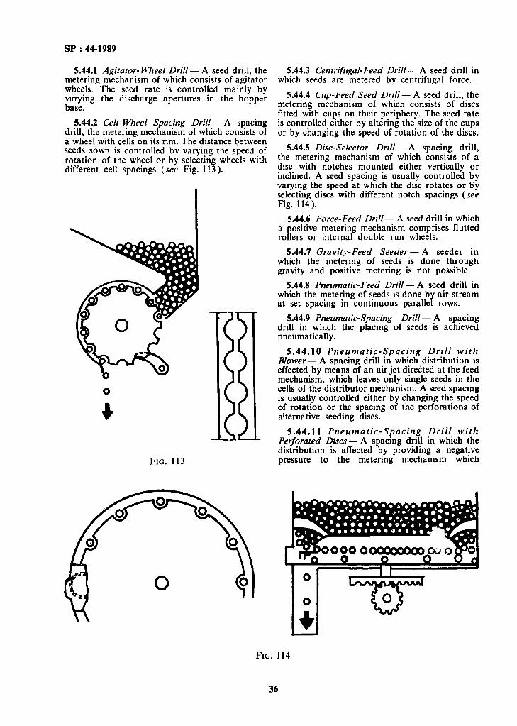
Transcript
Disclosure to Promote the Right To Information
Whereas the Parliament of India has set out to provide a practical regime of right to information for citizens to secure access to information under the control of public authorities, in order to promote transparency and accountability in the working of every public authority, and whereas the attached publication of the Bureau of Indian Standards is of particular interest to the public, particularly disadvantaged communities and those engaged in the pursuit of education and knowledge, the attached public safety standard is made available to promote the timely dissemination of this information in an accurate manner to the public.
इंटरनेट मानक
“!ान $ एक न' भारत का +नम-ण”Satyanarayan Gangaram Pitroda
“Invent a New India Using Knowledge”
“प0रा1 को छोड न' 5 तरफ”Jawaharlal Nehru
“Step Out From the Old to the New”
“जान1 का अ+धकार, जी1 का अ+धकार”Mazdoor Kisan Shakti Sangathan
“The Right to Information, The Right to Live”
“!ान एक ऐसा खजाना > जो कभी च0राया नहB जा सकता है”Bhartṛhari—Nītiśatakam
“Knowledge is such a treasure which cannot be stolen”
“Invent a New India Using Knowledge”
है”ह”ह
SP 44 (1989): Handbook of Agricultural MachineryTerminology [FAD 21: Farm Implements and Machinery]
Handbook of Agricultural Machinery
Terminology
‘Handbook of Agricultural Machinery
Terminology
BUREAU OF INDIAN STANDARDS MANAK BHAVAN, 9 BAHADUR SHAH ZAFA/R MARG
NEW DELHI 110002
SP 44 : 1989
FIRST PUBLISHED MARCH 1989
FIRST REPRINT JANUARY 1990 SECOND REPRINT SEPTEMBER 1993
0 BUREAU OF INDIAN STANDARDS
UDC 631&021) : 001.4
ISBN 81-7061-022-2
PRICE Rs 250.00
PRINTED IN INDIA AT KAPOOR ART PRESS, A3813 MAYAPURI, NEW DELHI 110064 AND PUBLISHED BY BUREAU OF INDlAN STANDARDS, NEW DELHI 110002
FOREWORD
With the increasing emphasis on farm mechanization for boosting agricultural production and for post-harvest processing, a large number of agricultural
machinery for various operations are being designed, developed, manufactured and used in the country. For providing authentic definition of the terms used in respect of various agricultural machinery, a number of Indian Standards have been brought out as well as some definitions covered in various product specifications. However, the need for consolidated publication covering all the terms has always been acutely felt.
It is hoped that the Handbook will help in the adoption of uniform definitions thereby facilitating interpretation and communication amongst various interests. The Handbook will also satisfy a longfelt need of agricultural engineering profession.
The terms included in the Handbook are grouped on the basis of sequence of operations performed by various equipment and are given in the following order :
4 General terms,
b) Tractors and power tillers,
cl Tillage,
4 Tillage equipment,
e) Sowing and fertilizers application equipment,
r) Intercultivation equipment,
8) Irrigation equipment and systems,
h) Horticultural equipment,
3 Forestry equipment,
k) Plant protection equipment,
m> Harvesting and threshing equipment,
4 Farm transport equipment, and
P) Processing equipment.
For ease of reference, an alphabetical index of the terms has been provided at the
end.
In case of dispute or ambiguity, the definitions, as appearing in the relevant standards (see Appendix A), shall be applicable.
CONTENTS
0.
I.
2.
3.
4.
5.
6.
7.
8.
9.
10.
11.
12.
13.
FOREWORD V
GENERAL TERMS
TERMS RELATING TO TRACTORS AND POWER TILLERS
TILLAGE
TILLAGE EQUIPMENT
4.1 Primary Tillage Equipment
4.2 Other Implements
4.3 Secondary Tillage Equipment.
SOWING AND FERTILIZER APPLICATION EQUIPMENT
INTERCULTIVATION EQUIPMENT
IRRIGATION EQUIPMENT
HORTICULTURAL EQUIPMENT
FORESTRY EQUIPMENT
CROP PROTECTION EQUlPMENT
HARVESTING AND THRESHING EQUIPMENT
FARM TRANSPORT EQUIPMENT
PROCESSING EQUIPMENT
PAGE
1
2
,,I 2
15
15
23
23
29
37
39
43
48
52
56
64
64
APPENDIX A 74
INDEX 75
SP : 44-1989
1. GENERAL TERMS
1.1 Animal-Drawn - Drawn by animal.
1.2 Belt-Driven - Operated by a driving belt and pulley.
1.3 Draft -The horizontal component of the pull.
1.4 Effective Field Capacity-The actual area covered by the implement based on its total time consumed and its width.
1.5 Engine-Driven - Operated by an engine.
1.6 Field Efficiency-The quotient of the effective field capacity and theoretical field capacity expressed in percentage.
1.17.2 Maintenance Instructions - A docu- ment which explains the maintenance and adjust- ment required, and the manner of under- taking work on the equipment at the operator’s level.
1.18 Parts Catalogue - A document which lists parts which are required to service the equipment. (It is recommended that this should be a separate publication).
1.19 Power Lift -- Raised or lowered by engine power.
1.20 Power Operated -Operated by a prime mover, such as engine, tractor, power tiller and electric motor.
1.21 Power-Take-Off (PTO) Driven - Operated by power-take-off of a tractor.
1.7 Ground Wheel Driven - Operated by a wheel 1.22 Pre-Delivery Set-Up Publications - Docu- in contact with the ground. ments which outline, in detail, the procedures for
1.8 Hand-Operated - Operated by hand. properly preparing equipment for delivery to the customer.
1.9 Implement - Equipment generally having no driven/moving parts, such as harrow or having only simple mechanisms such as piough.
1.10 Implement Drive Line -- The shafts, universal joints, connectors and fasteners provided with the implements to transmit rotational power from tractor power-take-off (PTO) to the first component on the implement, such as a gear set, pulley, sprocket or fly wheel.
1.11 Installation - Operations performed to make the tractor field-worthy to give trouble-free service for maximum working hours.
1.12 Machine-A combination of rigid or resistant bodies having definite motions and capable of performing useful work.
1.13 Manually-Operated - Operated by human beings.
1.14 Manufacturer-Any person or organization who actually manufactures tractor components fully or partially and assembles the tractor.
1.15 Mounted-Attached to a tractor so as to form a single unit and to be completely carried on the tractor when out of operation.
1.16 Operator - A person who actually operates the tractor. An operator may or may not be the user.
1.17 Operator’s Handbook - A document which explains the procedures for the proper operation and maintenance of the equipment.
1.17.1 Lubrication Instructions - A document which outlines ail aspects of lubrication of the equipment.
1.23 Preventive Maintenance - Systematic series of inspections and operations performed periodically to maintain or improve the efficiency and performance of the tractor.
1.24 Pull -The total force required to pull an implement.
1.25 Rated Engine Speed -The engine speed specified by the tractor manufacturer for continuous operation at full load.
1.26 Self-Lift - Raised or lowered by drive from a ground wheel or wheels.
1.27 Self-Propelled - Propelled and operated by a power unit or units integral with the machine.
1.28 Semi-Mounted -Partly carried on a tractor, both when in and out of operation.
1.29 Service Manual - A document which provides detailed procedures for the proper repair and/or overhaul of the equipment by a qualified mechanic.
1.30 Side Draft-The horizontal component of the pull perpendicular to the direction of motion. This is developed if the centre of resistance is not directly behind the centre of pull.
1.31 Soil Working Surface - Portion of a tool, implement or machine designed to be in contact with soil in order to effect proper manipulation.
1.32 Specific Fuel Consumption-The mass of fuel consumed per unit of work.
1.33 Steerage - Allowing limited lateral move- ment under manual control independent of the tractor.
1
SP : 44-1989
1.34 Supplier - Any person or organization appointed or recognized by the manufacturer for sale of tractor of his make. The manufacturer may or may not be a supplier.
1.35 Theoretical Field Capacity-The rate of field coverage of an implement based on 100 percent of time at the rated speed and covering 100 percent of its rated width.
1.36 Tool - An individual working element.
1.37 TractqrrOperated - Operated by a tractor.
1.38 Trailed - Drawn by a tractor but not carried on by it.
1.39 Unit Draft - Draft per unit cross-sectional area of the furrow.
1.40 User - Any person or organization who purchases and uses the tractor.
2. TERMS RELATING TO TRACTORS AND POWER TILLERS
2.1 Types
2.1.1 Agricultural Tractor - A self-propelled wheeled vehicle having two axles or a track-laying or semi-track-laying machine, more particularly designed to pull, push, carry, and operate implements and machines used for agricultural work (including forestry work).
2.1.1.1 Semi-track laying tractor - A tractor in which the means of propulsion in rear consist of an endless track(s) passing round the driving wheel(s) and the pinion(s), and the front wheels consist of pneumatic tyres.
2.1.1.2 Track laying tractor - A tractor in which the means of propulsion consist of an endless track(s) passing round the driving wheel(s) and the pinion(s).
2.1.1.3 Wheeled tractor - An agricultural tractor, with at least two axles, the means of propulsion of which consist of wheels generally fitted with pneumatic tyres.
a) Hillside tractor-A wheeled tractor equipped with manual or automatic means of compensating for sloping ground.
b) Self-propelled tool carrier - A wheeled tractor which, apart from the work it is able to accomphsh with implements placed behind or in front, is adapted and designed primarily for working with rigid full-width implements mounted between the axles.
c) Standard tractor - A wheeled tractor adapted and designed, more particularly bq’ its construction, for workihg with imple- ments and machines fixed behind or in front and interchangeable.
1) Standard tractor with four-wheel drive - A standard tractor whose engine power is
d)
e)
transmitted to the ground, both by the rear and the front wheels. The rear and the front wheels need not be of the same diameter.
2) Standard tractor with rear-wheel drive - A standard tractor whose engine power is transmitted to the ground exclusively by the rear driving wheels.
Tricycle tractor - A wheeled tractor which is supported on three or four wheels with both front or rear wheels placed very close.
Wasp-waisted tractor - A wheeled tractor which, depending on its type of construction, is not only suitable for working with implements and machines at front and rear but is also designed to operate under-slung implements.
2.1.2 Power Tiller - A prime mover in which direction of travel and its control for field operation is performed by the operator walking behind it. It is also known as hand or walking type tractor.
NOTE - Power tillers may be provided with the attachment for riding.
2.1.2.1 General purpose type - The power tiller which can be used for a number of farm operations including the types defined under 2.1.2.2 and 2.1.2.3.
2.1.2.2 Pull type- The power tiller which pulls various kinds of implements.
2.1.2.3 Tilling type - The power tiller which uses an engine power driven tilling device, such as rotary and crank or screw blades.
2.1.2.4 Track-laying power tiller - A power tiller propelled by tracks passing around the drive sprocket (see Fig. 1 ).
FIG. 1
2.1.2.5 Wheeled power tiller - A power tiller propelled by wheels fitted with pneumatic tyres.
a)
b)
2
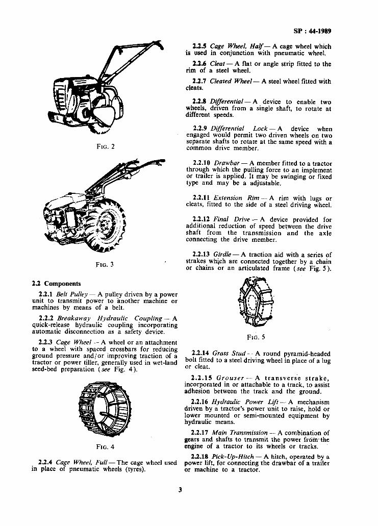
Single-wheel power tiller - A wheeled power tiller with one driving wheel (see Fig. 2).
Two-wheel power tiller - A wheeled power tiller with two driving wheels (see Fig. 3 ).
SP : 44-1989
FIG. 2
FIG. 3
2.2 Components
2.2.1 Belt Pulley - A pulley driven by a power unit to transmit power to another machine or machines by means of a belt.
2.2.2 Breakaway Hydraulic Coupling - A quick-release hydraulic coupling incorporating automatic disconnection as a safety device.
2.2.3 Cage Wheel- A wheel or an attachment to a wheel with spaced crossbars for reducing ground pressure and/or improving traction of a tractor or power tiller, generally used in wet-land seed-bed preparation (see Fig. 4).
FIG. 4
23.4 Cage Wheel, Full- The cage wheel used in place of pneumatic wheels (tyres).
2.2.5 Cage Wheel, HaF- A cage wheel which is used in conjunction with pneumatic wheel.
23.6 Cleat-A flat or angle strip fitted to the rim of a steel wheel.
23.1 Cleated Wheel- A steel wheel fitted with cleats.
2.2.8 Differential- A device to enable two wheels, driven from a single shaft, to rotate at different speeds.
2.2.9 Differential Lock - A device when engaged would permit two driven wheels on two separate shafts to rotate at the same speed with a common drive member.
2.2.10 Drawbar - A member fitted to a tractor through which the pulling force to an implement or trailer is applied. It may be swinging or fixed type and may be a adjustable.
2.2.11 Extension Rim-A rim with lugs or cleats, fitted to the side of a steel driving wheel.
2.2.12 Final Drive - A device provided for additional reduction of speed between the drive shaft from the transmission and the axle connecting the drive member.
2.2.13 Girdle - A traction aid with a series of strakes whjch are connected together by a chain or chains or an articulated frame (see Fig. 5).
FIG. 5
2.2.14 Grass Stud - A round pyramid-headed bolt fitted to a steel driving wheel in place of a lug or cleat.
2.2.15 Grouser - A transverse strake, incorporated in or attachable to a track, to assist adhesion between the track and the ground.
2.2.16 Hydraulic Power Lift - A mechanism driven by a tractor’s power unit to raise, hold or lower mounted or semi-mounted equipment by hydraulic means.
2.2.17 Main Transmission - A combination of gears and shafts to transmit the power from-the engine of a tractor to its wheels or tracks.
2.2.18 Pick-Up-Hitch - A hitch, operated by a power lift, for connecting the drawbar of a trailer or machine to a tractor.
3
SP : 44-1989
2.2.19 Pneumatic Tyred Wheel- A wheel fitted with a pneumatic tyre.
2.2.20 Power-Llyt -- A mechanism driven by a tractor’s power unit to raise or lower mounted or semi-mounted equipment.
2.2.21 Power Take-Off -~ A shaft, usually externally splined, to transmit torsional power to another machine. It is abbreviated as PTO (see Fig. 6).
TME- OFF TAKE-OFF WELD 0XJER~
FIG. 6
2.2.22 Power Take-Off Cover ---- A protective cap enclosing a power take-off (see Fig. 6).
2.2.23 Power- Take-Off Shield -- A rigid guard fitted on a tractor, covering the tractor power take-off as a safety device (see Fig. 6).
2.2.24 Quick-Release Hydraulic Coupling - A self-sealing’ coupling providing quick connection and disconnection of a tractor-to-implement hydraulic pipeline.
2.2.25 Road Band- A rim fitted to a steel wheel to prevent contact of the lugs or cleats with the road surface.
2’.2.26 Road Plates- Plates with a flat surface fitted to a track to prevent contact of the grousers with the ground.
2.2.21 Skeleton Wheel -- A steel wheel to give a minimum ground ccntact area (see Fig. 7).
FIG. 7
2.2.31 Steel CF’heel- A wheel made of steel generally fitted with spade lug:, or cleats.
2.2.32 Strakes An assembh of metal lugs or cleats attached to a pneumatic tyred Lvheel.
2.2.33 Three-Point Linkuge ~~ A combination of one upper link and two lower links. each articulated to the tractor and the implement at their ends. to connect the implement to the tractor (see Fig. X ).
2.2.33.1 Hitch point An articulated connection between a link and the implement. For geometrical purposes. the hitch point is the centre of the articulated connection hetwcen ;t link and the implement.
2.2.33.2 L_c\~cllitlg adjustI)lwt tay~~ (4 of Fig. 9 )-- The mobcment. measured vertically, of one lower hitch point higher or lower than the other, to provide an inclination to the implement.
2.2.33.3 Llf’t rods Connections that transmit force to the lower links for raising and lowering.
2.2.33.4 Linch pin A pin fitted \vith a spring retaining ring by which the lower and upper links of three-point linkage are retained in position at their hitch and link points.
NOTE -~ This 19 also used for retaining the implement with drawbar and also attachments like check chakns, etc.
2.2.33.5 Linch pin hole distunce ~~~ The distance from the centre line of a linch pin hole to the shoulder of the hitch pin.
2.2.33.6 Link point ~~ An articulated connection between a link and the tractor. For geometrical purposes, the link point is the centre of the articulated connection between a link and the tractor.
2.2.33.1 LoMjer hitch attachment ~~ A pin or clevis and pin usually attached to the implement, on which a lower link is secured.
2.2.33.8 Lower hitch point -- An articulated connection between a lower link and the implement.
2.2.33.9 Lower hitch point clearance (5 of Fig. 9)-The clearance expressed as a radial dimension from a lower hitch point to the outside diameter of the tyre, mud-guard or other ;>art of the tractor, measured in a longitudinal vertical plane with the implement in the raised position and all side away removed from the links.
2.2.28 Skid Ring -- A circumferential flange on 2.2.33.10 Lower hitch points height (3 of
the rim of a front wheel. Fig. 9)--- The height of the centre of the lower bitch Doints above ground level when thev are in
2.2.29 Spade Lug - A wedge-shaped metal fully iowered positron. ,
projection fitted to the rim of a steel wheel. 2.2.33.11 Lower hitch point span-The
2.2.30 Spark Arrester -- A device fitted with distance between the shoulders of the lower hitch the exhaust system of an engine to arrest the pins against which the sides of the lower link ball glowing carbon particles. swivals about.
4
SP : 44-1989
UPPER LINK POINT
+PPER HITCH POINT
-UPPER HITCH PIN
-LOWER LINK’ LOWER 1 I h&S
L LOWER HITCH POINT
\
LINCH PIN HOLE DISTANCE
FIG. 8
FIG. 9
$Y : 44-1989
2.2.33.12 Lower link point-An articulated connection between a lower link and the tractor.
2.2.33.13 Mast - The component that provides location of the upper hitch point on the implement.
2.2.33.14 Mast adjustment - The usable range of pitch of the mast in a vertical plane. It is measured as the maximum and the minimum heights of the lower hitch points above the ground between which a mast can be adjusted to any inclination between the vertical and 10” to the vertical towards the rear (see Fig. 10).
FIG. 10
NOTE - Adjustment of the mast controls the pitch of the implement. Specifying the mast adjustment to be provided, enables the tractor designer to determine the minimum acceptable adjustment of the length of the top link in relation to the points of attachment of the linkage. It also permits the implement designer to determine the range of operating depths of the implement over which pitch adjustment can be obtained.
2.2.33.15 Mast height - The vertical distance between the upper hitch point and the common axis of the lower hitch points.
2.2.33.16 Power range (2 of Fig. 9)-The total vertical movement of the lower hitch points corresponding to the power travel of the lift excluding any adjustment in the linkage of lift rods.
2.2.33.17 Transport height (1 of Fig. 9)- The height of the -lower hitch points above the ground utilizing the full extent of manual adjustment provided in the lift rods in conjunction with the power range, the lower hitch point axis being maintained horizontal to the ground in a transverse plane.
2.2.33.18 Three-point linkage check chain - A chain connected between each lower link and
the tractor to control the lateral movement of mounted -quipment (see Fig. 11).
,
LIFT ARM-, AlPPER LINH
FIG. 11
2.2.33.19 Three-point linkage stabilizer - A link connected between ends of one or both lower links and the tractor to hold mounted equipment in fixed lateral position in relation to the tractor.
2.2.33.20 Upper hitch pin - A pin, usually detachable and forming part of the upper link assembly by which the upper link is connected to the implement.
2.2.33.21 Upper hitch point-An articulated connection between the upper link and the implement.
2.2.33.22 Upper link and lower link- Elements of the linkage, each fitted with an articulated connection at both ends.
2.2.33.23 Upper link pin - A pin by which the upper link is connected to the tractor.
2.2.33.24 Upper link point - An articulated connection between the upper link and the tractor.
2.2.34 Track - A series of jointed track links or a flexible band forming an endless weight carrying rail to transmit and drive to the ground.
2.2.35 Variable Speed Governor - A mechanism to maintain the speed of a power unit at any selected value within a given range.
2.3 Dimensions
23.1 Ground Clearance
2.3.1.1 Ground clearance of power tiller - The height.of the lowest point of the power tiller chassis from a firm horizontal supporting surface (see E in Fig. 12).
2.3.1.2 Ground clearance of tractor - The height of the lowest point of the tractor chassis from a firm horizontal supporting surface, the tractor being ballasted as used for drawbar test (see E in Fig. 13).
6
SP : 44-1989
FIG. 12
FIG. 13
2.3.2 Height
2.3.2.1 Height of power tiller - The distance between a firm horizontal supporting surface and the horizontal plane touching the uppermost part of the power tiller wiph the engine in horizontal position (see D in Fig. 12).
2.3.2.2 Height of tractor-The distance between the firm horizontal supporting surface and the horizontal plane touching the uppermost part of the tractor (see D in Fig. 13).
2.3.3 Length-The distance between two vertical planes at right angles to the median plane of the tractor/power tiller and touching its front and rear extremities.
2.3.4 Minimum Clearance Diameter - The diameter of the smallest circle described by the outermost point of the projections of the tractor while executing its sharpest practical turn (see Fig. 14).
f CLEARANCE CIRCLE
FIG. 14
2.3.5 Minimum Turning Diameter - The diameter of the circular path described by the centre of tyre of the outermost wheel of the tractor while executing its sharpest practical turn (see Fig. 14).
2.3.6 Track (Tread)
2.3.6.1 Track of power tiller- The distance at the ground level between the median planes of the wheels on the same axle at stationary position and with the wheels in position for travelling in a straight line ( see A in Fig. 12).
2.3.6.2 Track of tracklaying tractors - The distance between the median planes of the tracks.
NOTE - The median plane of the wheel or track assembly is equidistant from the two planes containing the peripheries of the rims of the track plates respectively at their outer edge.
2.3.6.3 Track (tread) of wheeled tractor - The distance at ground level between the median planes of the wheels on the same axle, with the tractor stationary and with the wheels in position for travelling in a straight line. The track may be thus defined for both front and rear wheels. When there are twin wheels, the track is the distance between two planes each being the median plane of the pairs of wheels.
2.3.7 Wheel Base - The horizontal distance between the front and the rear wheels in the same
7
SP : 44-1919
plane measured at the centre of their ground contact.
2.3.8 Width-The distance between two vertical planes parallel to the median plane of the tractor/power tiller, each plane touching the outermost point of the tractor/power tiller on its respective side.
2.4 Mass
2.4.1 Dry Mass of Power Tiller-The mass of the power tiller fitted with all components necessary for its operation but without water, fuel and oil.
2.4.2 Mass of Ballasted Tractor - Mass of tractor as ballasted for drawbar test.
2.4.3 Operational Mass of Power Tiller-The mass of the power tiller in normal working condition with fuel tank and radiator full, and lubricants filled to the specified levels.
NOTE -Any accessory ktted and its mass should be stated.
2.4.4 Operational Mass of Tractor-The mass of the tractor in normal working condition with fuel tank and radiator full, lubricants, etc, filled to the specified levels and the mass of the driver (assumed to be 75 kg):
NOTE --- Any accessory fitted and its mass should also be stated.
2.5 Power
2.5.1 Belt Pulley Power - Power transmitted rhrough a belt with the governor control in the position recommended by the tractor manufacturer for belt pulley work. L
2.5.2 Drawbar Power - Power obtained at the drawbar with the governor control in the position recommended by the tractor manufacturer for drawbar work and the tractor moving on a horizontal surface with the drawbar pull applied horizontally.
2.5.3 Engine Power - Power tiasured at the crank shaft of the engine with the governor control lever in the position recommended by the manufacturer.
NO’TE - The engine should be fitted with all the accessories required for continuous operation; these should be set in the same relative position as when fitted in the tractor.
2.5.4 ‘Maximum. Drawbar Pull - The maximtim horizontal &‘Svbar pull, at a drawbar height recommended by the manufacturer, corresponding up to 15 percent wheels slip on standard concrete test track for wheel tractors and up to 7 percent track slip for track laying tractors on earthen test track which a tractor is able to sustain in the line of its longitudinal axis.
2.5.5 Power Outlet-Any outlet which transmits the engine power to the tractor in order
to make it functional, such as PTO, belt pulley and drawbar.
2.5.6 Power-Take-Off Power - Power obtained at the main power-take-off with the governor control in position recommended by the tractor manufacturer for PTO work, the tractor being stationary.
2.6 Power-Take-Off Connections
2.6.1 Male Shaft and Female Shaft-Male and female members respectively of a sliding assembly (see Fig. 15).
SHAFT GUARD
MALE SHAFT
2.6.2 Male
FIG. 15
Shaft Yoke and Female Shaft Yoke - Yokes attached to the male and female shaft respectively (see Fig. 15 ).
2.6.3 Power Znput Connection - An externally keywayed, splined or drilled stub shaft on a machine (see Fig. 15). It is abbreviated as PIC.
2.6.4 Power Input Connection Shield- A rigid guard fitted on a machine, shielding the power input connection (see Fig. 15).
2.6.5 Power Input Connection Yoke Boss- An internally keywayed, splined or drilled
member which receives a power input connection.
2.6.6 Power-Take-off and Power Znput
connection yoke bosses respectively or, in an appropriate context, a yoke itself (see Fig. 15).
2.6.7 Power-Take-Off Drive Shaft - The assembly from power-take-off yoke boss to power input connection yoke boss (inclusive) (see Fig. 15).
2.6.8 Power-Take-Off Drive Shaft Guard- A safety guard fitted over a power-take-off drive shaft ( see Fig. 15).
2.6.8.1 Non-rotating PTO drive shaft guard - A PTO drive shaft guard held stationary while the shaft is rotating.
2.6.8.2 Rotating PTO drive shaft guard - A PTO drive shaft guard which can rotate with the shaft except when it comes into contact with some other object.
2.6.9 Power-Take-Off Yoke Boss - An internally splined member which receives a power- take-off (see Fig. 15 ).
2.6.10 Shaft Closed Length - The distance between the centres of the journal cross- assemblies when the PTO drive shaft is fully closed.
2.6.11 Shaft Extended Length - The distance between the centres of the journal cross- assemblies when the PTO drive shaft is extended to the maximum length recommended by the manufacturer.
2.6.12 Universal Joint - A combination of two yokes and a yoke journal assembly (see Fig. 15 ).
SP : 44-1989
2.6.13 Yoke Journal Assembly - An assembly which couples two yokes.
2.7 Rear Tyres
2.7.1 Conventional Ply Tyre - A tyre in which the cords of the body plies run diagonally from bead to bead.
2.7.2 End of Lug Clearance-Distance from trailing side of a lug to end of the lug that follows (see Fig. 16).
2.7.3 Inflation Pressure - For air filled tyres, it is the gauge pressure measured with the valve in any position. For tyres containing liquid, it is the gauge pressure measured with the valve in the bottom position.
2.7.4 Lug Angle- The angle between the centre line of the lug face and the centre line of the tyre (see Fig. 16).
2.7.5 Lug Base-The projected thickness or width of the lug at the points where the projected planes of the leading and trailing sides meet the projected undertread face (see Fig. 16).
2.7.6 Lug Face - The outermost surface of the lug ( see Fig. 16 ).
2.7.7 Lug Fillet -The curved section which blends the lug sides into the undertread face (see Fig. 16).
2.7.8 Lug Height - Distance measured from the undertread face to the lug face (see Fig. 16).
I I /-LUG ANGLE
LUG SPACING PERPENDICULAR
LUG SPACING CIRCUMFER-
UNDERTREAD FACE
SECTION A A
FIG. 16
9
SP : 44-1989
2.7.9 Lug Length - Distance measured from end-to-end along the centre line of the lug face (see Fig. 16).
2.7.10 Lug Pitch - Centre-to-centre spacing of lugs on one side at the centre line of the tyre. It is measured at the lug face (see Fig. 16).
2.7.11 Lug Side - The lug surface between the undertread face and the lug face (see Fig. 16).
2.7.12 Lug Spacing, Circumferential-The distance from the leading side of a lug to the trailing side of the lug ahead of it, measured parallel to the centre line of the tyre (see Fig. 16).
2.7.13 Lug Spacing, Perpendicular - The distance, measured perpendicularly, from the leading side of a lug to the trailing side of the lug ahead of it (see Fig. 16 ).
2.7.14 Lug Taper- The angle, the lug side makes with a line parallel to the radius that extends from the centre line of the lug to the centre line of the wheel (see Fig. 16).
2.7.15 Lug Width-Width of lug face measured perpendicularly to the centre line of the lug face ( see Fig. 16 ).
2.7.16 Ply Rating- Identification of a given tyre with its maximum recommended load when used in a specific type of service. It is an index of the strength and does not necessarily represent the number of cord plies in the tyre.
2.7.17 Tread Width -The distance from shoulder to shoulder of a lug (see Fig. 16).
2.7.18 Undertread Face - The outermost surface of the rubber on the carcass where no lugs are located (see Fig. 16).
2.8 Speed
2.8.1 Maximum Travel Speed - The maximum attainable speed of the unladen tractor, where the engine speed governor has been set at the maximum top idle speed rating recommended by the manufacturer.
2.8.2 Theoretical Travelling Speed - The speed of the tractor determined at the rated engine speed for drawbar use, having regard to the total gear ratio and the effective radius of the driving wheels or tracks.
NOTE-~ the case of wheeled tractors, the tractor shall be under its own operational mass (without extra ballast), the tyre pressure as recommended by the manufacturer for field work, and the tyre lugs not worn more than l/3 of its normal height. .
2.9 Track-Type Traction Device
2.9.1 Angle of Approach - The angle between the ground and the section of track between the front bogie wheel and the front idler or sprocket (see Fig. 17).
2.9.2 Angle of Departure - The angle between the ground and the section of track between the rear bogie wheel and the rear idler or sprocket (see Fig. 17).
2.9.3 Grouser Height -Vertical distance from the track shoe face to tip of the grouser (see Fig. 17).
2.9.4 Grouser Width-Overall width of the grouser (see Fig. 17).
2.9.5 Grouser Spacing or Pitch - The distance between corresponding points on adjacent grousers (see Fig. 17).
2.9.6 Nominal Ground Contact Length - The horizontal distance between the centre of the drive sprocket and the front idler (see Fig. 17).
2.9.7 Track Pitch - Distance between corresponding points on adjacent track shoes (On band tracks, it is the distance between corresponding points on ‘adjacent drive lugs) (see Fig. 17).
2.9.8 Track Width-Overall width of an individual track (see Fig. 17).
2.10 Traction
2.10.1 Ballast - Any mass that can be added or removed from a tractor for the purpose of changing traction and stability.
2.10.2 Coefficients of Traction - Ratio of the total force output of the traction device in the direction of travel to the dynamic weight (normal force) on the traction device.
2.10.3 Coefficient of Vehicle Traction - Same as gross traction ratio (see 2.10.17).
2.10.4 Efficiency, Tractive - Output power divided by input power, usually expressed in percent.
2.10.5 Floatation - Ability of the traction device to resist sinkage into the medium being traversed.
2.10.6 Power, Input - Power input to traction device calculated from input torque and angular velocity of the driving axle.
2.10.7 Power, Output-Power output of a traction device calculated from net traction force and velocity in the direction of motion.
2.10.8 Rolling Circumference, Zero- Pull - Distance travelled per revolution of the traction
device with only enough input torque to overcome the rolling resistance.
210.9 Rolling Circumference, Zero-Torque - Distance travelled per revolution of the traction
device when being towed and with no torque between it and the axle.
10
SP : 44-1989
H
LL-J-----~O~~N~~ GROUND CONTACT LENGTH
. - -IT
hRACK ---i k-e--- TRACK PITCH WIDTH
GROUSER WIDTH
FIG. 17
11
GROUSER PITCH
SP :44-I989
2.10.10 Rolling Resistance of Non-driving Wheels - Force required, in the direction of travel, to overcome motion resistance of the non- driving wheels or transport device.
2.10.11 Slip- Relative movement in the direction of travel at the mutual contact surface of the traction device and the surface which supports it,
2.10.12 Thrust - Net traction plus rolling resistance of traction device while pulling.
2.10.13 Torque, Input - The moment measured between the driving axle and the traction device.
2.10.14 Traction Device - A device for propelling a vehicle using the reaction forces from the supporting surface.
2.10.15 Traction, Net - Force in direction of travel developed by the traction device and transferred to the vehicle.
2.10.16 Traction Ratio, Dynamic - Ratio of drawbar pull to actual force on traction device normal to traction surface while pulling.
2.10.17 Traction Ratio, Gross - Ratio of drawbar pull to total weight of vehicle.
2.10.18 Travel Ratio - Ratio of distance travelled per revolution of the traction device while pulling to the distance travelled per revolution of the traction device with zero drawbar pull of vehicle or zero net traction of traction device only.
2.10.19 Travel Reduction - One (1) minus travel ratio.
2.10.20 Weight, Dynamic - Total force exerted by the traction device normal to the supporting surface under operating conditions.
2.10.21 Weight, Static -Total vertical force exerted by the traction device when stationary, on a level surface, and with zero drawbar pull.
r FURROW
2.10.22 Weight Transfer-The change in normal forces on the supporting devices (traction and transporting) on a vehicle under operating conditions as compared to a static vehicle on a level surface.
3. TILLAGE
3.1 Adhered Soil Bodies - Masses of soil which adhere on soil working surfaces and act as a part of the tool. Soil bodies may be stationary or in a relatively slow motion.
3.1.1 Soil Cone- An adhered soil body which resembles a cone.
3.1.2 Soil Sheet - An adhered soil body which covers a large area of a tool like a sheet.
3.1.3 Soil Wedge - An adhered soil body which resembles a narrow vedge.
3.2 Aggregates - Agglomerations of primary soil particles produced by natural processes.
3.3 Anchoring - A tillage operation used to partially bury and thereby preventing movement of foreign materials such as plant residue or paper mulches.
3.4 Back Furrow - A raised ridge left at the centre of the strip of land when ploughing is started from centre to side (see Fig. 18).
3.5 Bedded Land -The land which is broken in alternate back furrows and dead furrows.
3.6 Bedding - A tillage operation which places soil into a specific configuration.
3.7 Broadcast Tillage - Coverage of an entire area as contrasted to a partial coverage as in bands or strips. It is also known as overall tillage.
3.8 Bulldozing-The pushing and rolling of soil by an inclined blade.
3.9 Chiseling - A tillage operation in which a narrow tool is used to break up hard pan in the
I
BACK FURROW
FIG. I8
12
SP : 44-1989
3.24 Intercultivation - Soil cultivation performed in standing crop.
3.25 Land Forming - Tillage operation which move soil to create desired soil configurations. Forming may be done on a large scale such as contouring or terracing, or on a small scale such as ridging or pitting.
3.25.1 Land Grading - Tillage operation which moves soil to establish a desired soil elevation and slope, such as levelling, contouring, cutting and filling.
3.252 Lund Plaining - Tillage operation that cuts and moves small layers of soil to provide a smooth and refined surface.
3.26 Levelling - The tillage operation in which the soil is moved to establish a desired soil elevation slope.
3.27 Listed Land-See 3.5.
3.28 Listing - A tillage and land-forming operation using a tool which splits the soil and turns two furrows laterally in opposite directions, thereby providing a ridge-and-furrow soil configuration.
3.29 Mechanical Impedance - The mechanical resistance of the soil to the movement of plant roots or tillage tools.
3.30 Mechanical Stability - The degree of resistance of the soil to the deformation or breakdown by a specified mechanical force.
3.31 Mechanical Strength -The mechanical resistance of soil to deformation or separation by forces.
3.31.1 Bulk Strength - The mechanical strength of the overall soil mass as contrasted to the strength of loose but individually strong clods, fragments or aggregates.
3.31.2 Clod Strength - The mechanical strength of individual soil clod.
3.32 Middle Breakin -The use of a lister in a manner that opens t % e furrow midway between two previous rows of plants.
3.33 Minimum Tillage - The minimum soil manipulation necessary to meet tillage requirements for crop production.
3.34 Mixing -see 3.23.
soil. It is usually performed at a depth greater than the normal ploughing depth.
3.10 Clods- Soil blocks or masses that are cut, sheared or broken loose by tillage tools.
3.11 Combined Tillage Operations - Operations simultaneously utilizing two or more different types of tillage tools or implements (subsoiler- lister, lister-planter or plough-planter combinations) to simplify, control or reduce the number of operations over a field.
3.12 Concretions - Soil structural units which are irreversibly cemented together.
3.13 Conventional Tillage -The combined primary and secondary tillage operations normally performed in preparing a seed bed.
3.14 Dead Furrow - An open trench left in between two adjacent strips of land after finishing of ploughing (see Fig. 19 ).
3.15 Deep Tillage - A primary tillage operation which manipulates soil to a greater depth than normal ploughing. It may be accomplished with a heavy-duty mould board or disc plough which inverts the soil, or with a chisel plough or subsoiler which shatters soil.
3.16 Depth of Cut - The maximum depth of the penetration of the tool measured with reference to the initial soil surface.
3.17 Earth Moving - Tillage action and transport operations utilized to loosen, load, carry and unload soil.
1 3.18 Foreign Body - Foreign objects including pieces of tiles, pipes, wires, or crushed rock that occur in or have been inserted in soil.
3.19 Foreign Materials-All foreign matter in soils including residues, soil additives and foreign bodies that have not originated in the development of the soil.
3.20 Fragments - Masses of soil which are created by fracture along natural surfaces of weakness.
3.21 Furrow-The trench formed by a tool in the soil during operation (see Fig. 20).
3.21.1 Furrow Crown -The peak of the turned furrow slice (see Fig. 20).
3.21.2 Furrow Slice-The soil mass cut and turned by tool (see Fig. 20).
3.21.3 Furrow Sole-The bottom surface of the furrow (see Fig. 20).
3.21.4 Furrow Wall-The undisturbed side of furrow (see Fig. 20).
3.22 Harrowing - A secondary tillage operation which pulverizes, smoothens and packs the soil in seedbed preparation and/ or controls weeds.
3.23 Incorporating - Tillage operations which mix or disperse foreign materials, such as chemicals or plant residues into the soil.
3.35 Mulch Tillage - Preparation of soil in such a way that plant residues or other mulching materials are specially left on or near the surface.
3.36 Optimum Tillage - A system of tillage contributing to maximum net return for a crop under given field conditions.
3.37 Oriented Tillage - Tillage operations which are oriented in specific paths or directions with respect to the sun? prevailing winds, previous tillage actions or field base lines.
13
SP : 44-1989
DEAD FURROW FURROW
FIG. 19
FURROW
‘;; /-- CROWN
SLICE
FURROW WALL
I- FURROW SOLE c’
m
/-FURRow
FIG. 20
3.38 Peds - See 3.2.
3.39 Ploughing - A primary tillage operation which is performed to cut, break and invert the soil partially or completely.
3.39.1 Contour Ploughing - The method of ploughing in which the Soil is broken and turned along contours.
339.2 Normal Ploughing - Ploughing up to a depth of 15 cm.
3.40 Primary Tillage - Tillage operations which constitute the initial major soil-working operation. It is normally designed to, reduce soil strength, cover plant materials and re-arrange aggregates.
3.41 Puddling - The mechanical manipulation of soil in the presence of standing water in the field to create and impervious hard
P an below the
puddle zone so as to prevent loss o water through
leaching and facilitate transplanting of paddy seedlings by making the soil softer.
3.42 Pulverization - The general fragmentation of a soil mass resulting from the action of tillage forces.
3.43 Reduced Tillage - A tillage system in which the primary tillage operation is performed in conjunction with special planting procedure in order to reduce or eliminate secondary tillage operations.
3.44 Residue - Foreign materials including roots, remaining in or on the soil in significant amounts such that they can be detected, or that they can exert a separate and distinct influence on soil properties or machinery operations.
3.45 Residue Processing - Operations that cut, crush, anchor or otherwise handle residues in conjunction with soil manipulation.
3.46 Ridging - See 3.6.
3.47 Root Bed -The soil profile modified by tillage or amendments for use by plant roots.
3.48 Root Zone -The part of soil profile exploited by the roots of plants.
3.49, Rotary Tillage - Tillage operation employing rotary action to cut, break and mix soil.
3.50 Scouring - A soil-tool reaction in which soil slides over the soil engaging surface of tillage tool without significant adhesion.
3.51 Secondary Tillage - Tillage operations, following primary tillage, which are performed to create proper soil tilth for seeding and planting.
3.52 Seed Bed-The soil zone which affects the germination of seeds and emergence of seedlings.
3.53 Shear Blocks - The blocks of soil which are sheared loose from the main soil mass as a result of ultimate shearing strains applied by tillage tools.
3.54 Shear Surface - Failure surfaces occurring where the soil has sheared.
3.54.1 Primary Shear Surfaces - The initial and distinct, shear surfaces which appear during failure and are caused mainly by soil movement resulting from the advance of a tool.
3.54.2 Secondary Shear Surfaces - Shear surfaces which result from the twisting, pushing or tumbling of the soil after or during the initial displacement. Secondary shear surfaces are often perpendicular to the primary shear surfaces.
3.55 Soil Abrasion -The scratching, cutting or abrading of tillage tools caused by the action of soil.
3.56 Soil Additives - Foreign materials, other than seeds, which are added to or incorporated in soil for directly influencing the soil condition or environment. These include pesticides, fertilizers, mulches, or conditioners but not foreign bodies, such as drain tiles which have an indirect influence.
3.57 Soil Adhesion-The sticking of soil to tillage tools or wheels.
3.58 Soil Compaction - Reduction in the specific volume of soil by means of mechanical manipulation.
3.59 Soil Cultivation - Tillage operations performed to create soil conditions conducive to improve aeration, infiltration, compaction and moisture conservation as well as to control weeds.
3.60 Soil Cutting - Soil separation from the soil mass by slicing action.
3.61 of a such
3.62
SP : 44-1989
Soil Failure - The alteration or destruction soil structure caused by mechanical forces, as shear, compression and impact.
Soil Heaving - The swelling of soil resulting from natural forces such as freezing.
3.63 Soil Reaction -The reaction caused by the application of mechanical forces to the soil.
3.64 Soil Shatter - See 3.42.
~.u6~a~eoil Slicing-The slicing of soil across a
3.66 Strip Tillage - A tillage system in which only isolated bands of soil are tilled.
3.67 Sub-soiling - Chiseling at depth greater than 40 cm.
3.68 Throw -The movement of soil in any direction as a result of kinetic energy imparted to the soil by tillage tool.
3.69 Tillability - The degree of ease with which a soil may be manipulated for a specific purpose.
3.70 Tillage - The mechanical manipulation of soil for any purpose; but in agriculture the term is usually restricted to the changing of soil conditions for crop production.
3.71 Tillage Action -The action of a tillage tool in executing a specific form of soil manipulation, such as soil cutting, pulverizing or inversion.
3.72 Tillage Depth-Vertical distance from the initial soil surface to a specific point of penetration of the tool.
3.73 Vertical Mulching - A sub-soiling operation in which a vertical band of mulching material is put in the soil.
3.74 Weeding - Eradication of unwanted plants from the field.
4. TILLAGE EQUIPMENT
4.1 Primary Tillage Equipment
4.1.1 Plough - An implement used to cut the furrow slice with partial or complete soil inversion and in some cases to break it (see Fig. 21 ).
4.1.1.1 Types of ploughs
1) Alternate plough - A plough having an even number of bodies turning to right and left respectively and mounted side by side, which can be raised or lowered separately turning about a transverse axis (see Fig. 22).
2) Balance plough - A plough with bodies mounted facing one another on beams or frames which are situated on opposite sides of transverse axis and are joined together at an obtuse angle. The plough is not turned at the ends of the field, but are partially rotated about the axis and works
15
1 HANDLE GRIP
P \
0 / Q 0 / 0 1
9 / / / / / / /
.oBOARo
/ - \ WARF
LANOSM J - .e.._.-
FIG. 21
FIG. 22
to and fro with right and left bodies alternately in work (see Fig. 23).
3) Chisel plough - A plough used to cut through hard soils by means of one or a number of narrow tines.
FIG. 23
4) Disc plough - A plough the working parts of which are concave or truncated cone discs which act simultaneously as mould board and share (see Fig. 24).
FIG. 24
i) Framed plough - A plough the body (or bodies) of which is (are) attached to a framed beam.
ii) Gallows plough - An animal-drawn plough, the end of the beam rests freely on a bolster fixed to two front wheels, which is drawn through the front wheel assembly (see Fig. 25).
5) Gangplough - A riding plough with two or more bottoms.
6) Lister plough - A mouldboard plough with double mouldboards for throwing the soil in opposite directions.
16
SP : 44-1989
FIG. 25
7) Mouldboard plough - A plough with share and mouldboard which cuts furrow slice, lifts and inverts it.
8) Off-set plough - A plough with off-set beam to work borders and headland.
ii) Reversible plough, roll-over type - A plough of which the right and left bottoms (bodies) are on opposite sides of a transverse axis, perpendicular to the direction of travel, about which they. can turn 180’ (see Fig. 28).
9) One-way plough - A plough which turns the furrow slice in the same direction with respect to the forward travel (see Fig. 26).
FIG. 28
iii) Reversible plough, turnwrest type - A plough in which a compound body is turned from the right to the left hand by rotating it through approximately 180” about a longitudinal axis (see Fig. 29).
FIG. 26
10) Pore hal- A narrow wooden plough with sowing attachment.
11) Reversible plough - A plough which turns the furrow slice to the right and to the left alternatively with respect to the forward travel.
i) Reversible plough, half-turn type - A plough with bottoms (bodies) mounted on opposite sides of a beam or frame which can be rotated approximately 180” about a longitudinal axis (see- Fig. 27). -
FIG. 29
iv) Reversible plough, quarter-turn type - A slough of which the bottoms (bodies) mounted &I the same beam are fixed at an angle of 90” to each other and able to pivot through a quarte,r circle about the longitudinal axis (see Fig. 30 ).
FIG. 27
v) Riding plough- A plough balanced on wheels and on which the operator rides during the operation.
12) Rotary plough - A plough used to cut and to pulverize soil by impact forces by means of a number of rotating tines or knives which are mounted on a horizontal rotar.
SP : 44-1989
FIG. 30
13) Rotating auger plough (combinous) - A plough with short plough bottom followed with
15) Stump-jump plough - A plough with spring-loaded plough bottom or discs which rides
vertical rotars having blades (see Fig. 31 ). over stumps and other obstructions in the soil (see Fig. 33 ).
FIG. 31
14) Stubble plough - A plough specially designed to turn over and bury stubble (see Fig. 32).
FIG. 32
FIG. 33
16) Sub-soiler - A plough designed to penetrate the soil to depths more than those achieved during normal ploughing operation, usually 40 cm or more.
17. Sulky plough - A single bottom riding plough.
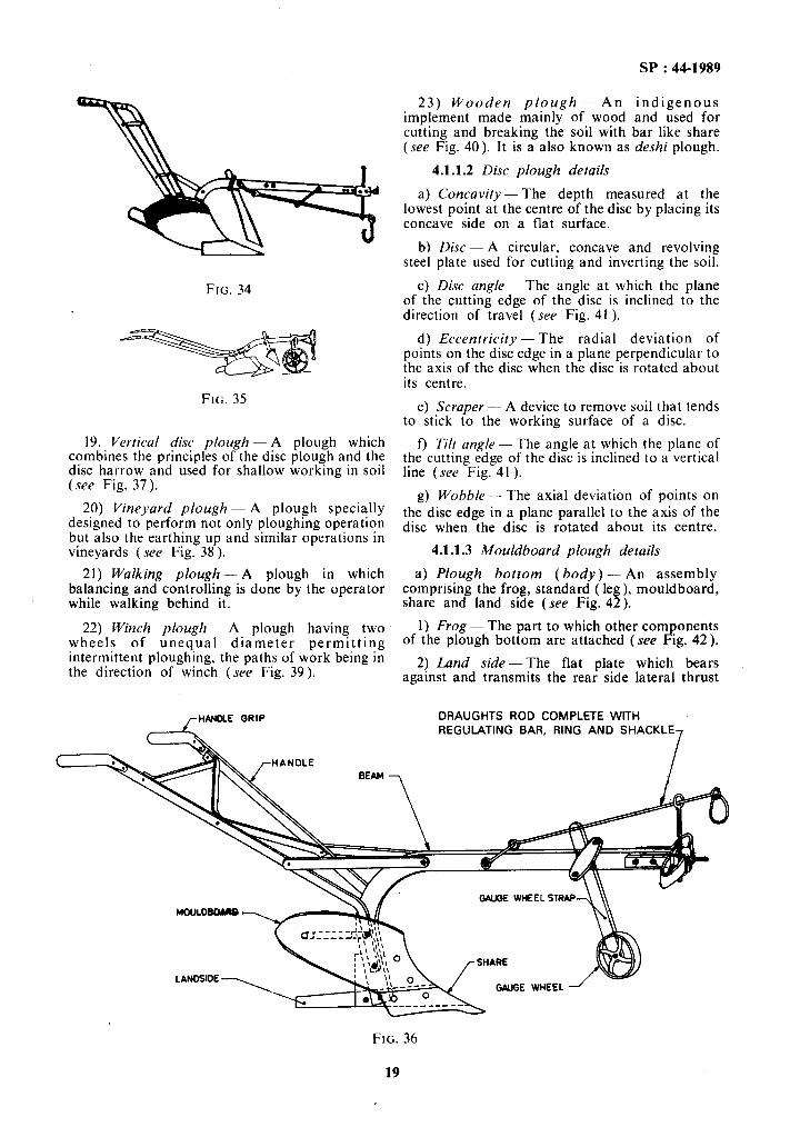
i) Swing plough - An animal-drawn plough without supporting wheel whose stability is ensured by the handles, the depth and width of work being regulated by using a draft adjustment (see Fig. 34).
ii) Double-wheel plough - A swing plough with a land and a furrow wheel mounted on vertical standards on a crossbar (see Fig. 35).
iii) Single-wheel plough - A swing plough provided with a wheel or a toe at the front (see Fig. 36)
18) Trip beam plough - A plough with a latch or trip mechanism which permits the body to swing back to ride over an obstruction.
18
FIG. 34
FIG. 35
19. Vertical disc plough - A plough which combines the principles of the disc plough and the disc harrow and used for shallow working in soil (see Fig. 37).
20) Vineyard plough -- A plough specially designed to perform not only ploughing operation but also the earthing up and similar operations in vineyards (see Fig. 38 ).
21) Walking piough - A plough in which balancing and controlling is done by the operator while walking behind it.
22) Winch plough- A plough having two wheels of unequal diameter permitting intermittent ploughing, the paths of work being in the direction of winch (see Fig. 39).
HANDLE QRIP
SP : 44-1989
23) Wooden plough - An indigenous implement made mainly of wood and used for cutting and breaking the soil with bar like share (see Fig. 40). It is a also known as deshi plough.
4.1.1.2 Disc plough details
a) Concavity- The depth measured at the lowest point at the centre of the disc by placing its concave side on a flat surface.
b) Disc -- A circular, concave and revolving steel plate used for cutting and inverting the soil.
c) Disc angle-The angle at which the plane of the cutting edge of the disc is inclined to the direction of travel (see Fig. 41 ).
d) Eccentricity - The radial deviation of points on the disc edge in a plane perpendicular to the axis of the disc when the disc is rotated about its centre.
e) Scraper - A device to remove soil that tends to stick to the working surface of a disc.
f) Tilt angle - The angle at which the plane of the cutting edge of the disc is inclined to a vertical line (see Fig. 41).
g) Wobble-The axial deviation of points on the disc edge in a plane parallel to the axis of the disc when the disc is rotated about its centre.
4.1.1.3 Mouldboard plough details
a) Plough bottom (body) - An assembly comprising the frog, standard (leg), mouldboard, share and land side (see Fig. 42).
1) Frog- The part to which other corn onents of the plough bottom are attached (see F!g. 42).
2) Land side- The flat plate which bears against and transmits the rear side lateral thrust
DRAUGHTS ROD COMPLETE WITH REGULATING BAR, RING AND SHACKLE
GAUGE WHEEL STRAP
MOULDEOARB
GWGE WHEEL
FIG. 36
SP : 44-1989
FIG. 37
FIG. 38
FIG. 39
GROUND LINE
FIG. 41
of the plough bottom to the furrow wall (see Fig. 42).
T WING BEARING
L SHIN
FIG. 42
i) Heel of land side - The rear underside of the land side which slides along the furrow sole (see Fig. 42).
ii) Replaceable heel- A heel of the !,lnd side which is replaceable.
3) Edge clearance - The maximum clearance between the cutting edge of share and straight line touching the point of share and wing of share (see Fig. 42).
4) Wing bearing- The level portion of the wing of the share providing a bearing for the outer corner of the plough bottom (see Fig. 42 ).
5) Tail piece - An adjustable extension which can be fastened to the rear of a mouldboard to help in turning or comprising a furrow slice (see Fig. 43).
20
SP : 44-1989
-.-- _ _ SIDE CAPI
SHARE -
-HEEL
FIG. 43
6) Knife tail piece - A tail piece to cut a furrow slice.
7) Side cap - A plate fitted above a land side (see Fig. 43).
8) Shade - A horizontal plate bearing on a furrow bottom, usually integral with a land side (see Fig. 43 ).
9) Standard (leg) - The part connecting the soil’cutting unit of the implement to the beam. In a curved beam, the standard is a part of the beam (see Fig. 43 ).
10) Beam - A rigid member connecting the plough bottom with power source (see Fig. 43 ).
11) Mouldboard - The curved part which lifts and turns the furrow slice (see Fig. 43).
i) Shin of mouldboard - The edge of the mouldboard which lies in a vertical plane (see Fig. 43 ).
ii) General purpose mouldboard- A mouldboard having a medium curvature lying between stubble and sod (see Fig. 44).
GENERAL PURPOSE STUBBLE MOULDBOARD MOULDBOARO
SOD OR BREAKER HOULDBOARD
SLAT MOULDBOARD
FIG. 44
iii) Rod mouldboard- A mouldboard consisting of rods.
iv) Slat mouldboard - A mouldboard the surface of which is made of slats placed along the length of the mouldboard (see Fig. 44).
v) Sod mouldboard or breaker mouldboard - A long mouldboard with a gentle curvature which lifts and inverts unbroken furrow slice (see Fig. 44).
vi) Solid moutdboard- A mouldboard with unbroken surface.
vii) Stubble mouldboard- A short but broader mouldboard with a relatively abrupt curvature which lifts, breaks and turns the furrow slice used in stubble soils (see Fig. 44).
12) Share - The parts of the plough bottom which penetrates into the soil and makes a horizontal cut below the surface (see Fig. 45 ).
i) Cutting edge-The front edge of the share which makes the horizontal cut in the soil (see Fig. 45).
/- GUNNEL
CUTTING EDGE
FIG. 45
ii) Gunnel-The vertical face of the share which rubs against the furrow wall (see Fig. 45).
iii) Share point-The leading end of the cutting edge which facilitates the penetration of a share into the soil (see Fig. 45).
iv) Wing of share-The right or left end of the cutting edge of share in right or left hand ploughs (see Fig. 45 ).
v) Bar-point share - A share in which the point of the share is provided by an adjustable and replaceable bar (see Fig. 46).
SHARE JI
FIG. 46
vi) Shine share - A share having a shin as an additional part.
vii) Slip-nose share - A share with detachable point.
viii) Slip share - A one piece share with curved cutting edge, having no additional part.
21
SP : 44-1989
ix) Straight share- A share with straight cutting edge.
b) Drawbar--The member that connects a trailed plough to a tractor.
c) Safety hitch - A hitch incorporating a device to avoid breakage when a plough works against an abnormal resistance.
d) Gauge wheel- An auxiliary wheel of an implement to maintain a uniform depth of working.
e) Horizontal clevis - A device to effect lateral adjustment of the plough relative to the line of pull.
f) Vertical clevis- A vertical plate with a number of holes at the end of the beam to control the depth of operation and adjust line of pull.
g) Front furrow wheel - The front wheel of a plough which runs in the furrow (see Fig. 47).
FIG. 47
h) Land wheel - The wheel of a plough which runs on the unploughed land (see Fig. 47).
j) Rear furrow wheel -The rear wheel of the plough which runs in the furrow (see Fig. 47).
k) Coulter - A device to cut the soil vertically from the land ahead of the plough bottom.
1) Stationary (knife) coulter - A stationary blade fixed downward in a vertical position on the beam (see Fig. 48).
FIG. 48
22
2) Disc couher - A circular flat or concave revolving steel disc fitted to the beam through a shank and yoke (see Fig. 49).
3) Shank qf coulter - The part that connects the coulter to the plough beam (see Fig. 49).
SHANK OULTER
LDISC COULTER
FIG. 49
m) Jointer- A device which resembles a miniature plough bottom which cuts and turns over a small ribbon-like furrow slice directly ahead of the plough bottom (see Fig. 49).
n) Levelling control mechanism - A lever or other mechanism to level a plough transversely.
p) Levelling control lever -The lever which operates the levelling control mechanism.
q) Horizontal clearance (side clearance) - The maximum clearance between land side and a horizontal plane touching point of share at its gunnel side and heel of landside. It is also known as horizontal suction (see Fig. SO).
‘&IDE CLEARANCE
FIG. 50
r) Vertical clearance - The maximum clearance under the land side and horizontal surface when the plough is resting on a horizontal surface in the working position. It is also known as vertical suction (see Fig. 5 1).
s) Throat clearance - The perpendicular distance between point of share and lower portion of the beam (see Fig. 52).
t) Centre of power -The true point of hitch (see Fig. 53 ).
SP : 44-1989
VERTICAL CLEARANCE
FIG. 51
FIG. 52
u) Cen.tre of resistance- The point at which the resultant of all the horizontal and vertical forces act (see Fig. 53 ).
w) Line of pull - An imaginary straight line passing from the centre of resistance through the clevis to the centre of pull (see Fig. 53).
4.1 .1.4 Wooden plough details
a) Body-The main frame to which shoe, beam and handle are attached.
b) Share - A narrow steel bar attached to the upper surface of the shoe longitudinally along the central line and projecting slightly out.
c) Shoe - The wedge-shaped lower portion of the plough which moves inside the soil.
4.2 Other Implements
4.2.1 Bakkhar - An implement, consisting of one or more blades atiached to a beam or frame, used for shallow working of soil with minimum of soil inversion. It is also known as blade harrow.
,-CENTRE OF rCLEVlS
4.2.2 Basin Lister- An implement which makes continuous ridges with furrows in between the ridges.
4.2.3 Bund Former - An implement which gathers soil and forms a bund (see Fig. 54).
4.2.4 Ditcher - An implement used for making ditcpes.
4.2.5 Lund Plane-An implement used for smoothening and planing the soil surface.
4.2.6 Leveller - An implement for smoothen- ing the surface of uneven tilled land (see Fig. 55).
4.2.7 Puddler - An implement used for churning the soil in standing water.
4.2.7.1 Plank puddler - A puddler consis- ting of a wooden plank provided with a number of small spikes on one edge and a handle at the centre of the other edge.
4.L7.2 Kotary pud2ier -- A puddler with blahes fixed on a horizontal shaft (see Fig. 56).
4.2.8 Ridger - An implement which cuts and turns the soil in two opposite directions simultaneously for forming ridges ( see Fig. 57 ). It is also known as furrower.
4.2.9 Soil Scoop - An implemerit used to collect and move soil from one spot to another (see Fig. 58 ).
4.3 Secondary Tillage Equipment
4.3.1 Float - An implement used down and smoothening the surface of Fig. 59).
for packing the soil (see
4.3.2 Harrow - An implement used to break the clods after ploughing to collect trash from the ploughed land, to level the seed bed and to mix the material with the soil.
4.3.2.1 Chain harrow> - A harrow consisting of a frameless network of links (see Fig. 60).
4.3.2.2 Disc harroM3 - A harrow which performs the harrowing operations by means of a set (or a number of sets) of rotating steel discs, each set being mounted on a common shaft.
FIG. 53
23
SP : 44-1989
FIG. 54
a) Double-action disc harrow - A disc harrow consisting of two or more gangs in which a set of one or more gangs follows behind the set of the other one or more arranged in such a way that the front and back gangs throw the soil in opposite directions.
I) Off-set disc harrow - A disc harrow with two gangs in tandem, capable of being off-set to either side of the centre line of pull (see Fig. 61).
2) Tandem disc harrow-A disc harrow comprising four gangs with provision of angling m opposite direction (see Fig. 62).
FIG. 56
FIG. 57
FIG. 58
FIG. 59
24
c SP : 44-1989
FIG. 60
FIG. 61
FIG. 62
b) Single action disc harrow - A disc harrow with two gangs placed end-to-end displacing the soil outwardly (see Fig. 63).
3) Gang - An assembly ot concave discs mounted on a common shaft with spools in between.
4) Gang angle - The angle between the axis of the gang and the line perpendicular to the direction of travel.
5) Gang axle (arbor axle) - A shaft on which a set of discs are mounted.
6) Gang control lever - A lever which operates the angling mechanism of disc harrow.
7) Spool (spacer) - The flanged tube mounted on the gang axle between every two discs to retain them at fixed position on the shaft.
4.3.2.3 Flexible tine harrow - A harrow consisting of network of spring tines (see Fig. 64).
FIG. 64
4.3.2.4 Reciprocating power harrow - A harrow fitted with rigid tines driven by the power- take-off in a reciprocating transverse or rotary motion as the machine travels forward (see Fig. 65).
FIG. 63
c) Disc harrow details
I) Angling mechanism - A mechanism by means of which the gang angles are adjusted.
2) Disc spacing - The transverse distance between the edges of two discs separated by a spool.
FIG. 65
25
.
43.2.5 Rolling or rotary harrow - A harrow consisting of rigid or flexible tines mounted on one or more horizontal or vertical shafts. It is also known as gyro harrow.
SP : 44-1989
a) Cage harrow - A rolling harrow with horizontal shafts each fitted with star-shaped tines Jomed by rods forming the lines of cylinder (see Fig. 66).
FIG. 66
b) Circular harrow - A rolling harrow consisting of a circular frame fitted with teeth and turning about a shaft slightly inclined towards the vertical (see Fig. 67).
FIG. 67
c) Clod crusher- A rolling harrow with horizontal shafts fitted with star shaped tines (see Fig. 68).
FIG. 68
d) Roller horrow - A roiling harrow with a horizontal shaft consisting of a light roller with projecting teeth (see Fig. 69).
FIG. 69
4.3.2.6 Spike-tooth harrow - A harrow with pegs as working part fitted on rigid, articulated or flexible frame (see Fig. 70).
FIG. 70
4.3.2.7 Spring-tooth harrow - A harrow with tough and flexible teeth designed primarily to work in hard and stony soils (see Fig. 71).
FIG. 71
433.8 Triangular harrow - A spike-tooth harrow with a triangular frame (see Fig. 72).
26
SP : 44-1989
FIG. 72
4.3.2.9 Zigzag harrow - A spike-tooth harrow with a zigzag frame and teeth attached at the junctions of frame members (see Fig. 73).
FIG. 73
4.3.3 Patela - A wooden plank used for smoothening the soil and crushing the clods. In certain cases weeds can be collected with the help of the curved spikes attached behind the wooden board (see Fig. 74).
FIG. 14
4.3.4 Roller - An implement with parts mounted on a horizontal shaft used for compacting the soil and crushing the clods.
4.3.4.1 Cage roller - Roller consisting of a cage of metal bars arranged so as to form the shape of a cylinder (see Fig. 75).
FIG. 75
4.3.4.2 Cambridge roller - Roller corn rising a number of thick discs, each having the orm of two frusta of a cone with a smooth F periphery, joined base-to-base and placed on the same shaft without gap (see Fig. 76).
FIG. 76
4.3.4.3 Coil roller - Roller having the form of a cylindrical cage circumscribed by a spiral (see Fig. 77).
FIG. 77
4.3.4.4 Continental Cambridge roller - Roller comprising discs of unequal diameters and of alternating smooth and notched surface placed on the same shaft (see Fig. 78).
4.3.4.5 Corrugated roller - RoHer consisting of one or more cylinders of which the surface has corrugations in a concentric form or parallel to the axis of the cylinder (see Fig. 79).
43.4.6 Cross-kill roller - Roller comprising metallic discs placed on the same shaft. These
21
SP : 44-1989
FIG. 78
FIG. 79
rough-surfaced discs have unequal projections on their periphery (see Fig. 80).
FIG. 80
4.3.4.1 Flat roller - Roller consisting of one or more hollow or solid cylinders with a smooth surface (see Fig. 8 1).
4.3.4.8 Furrow press - Roller comprising a number of spoked wheels of larger diameter and
FIG. 81
more widely spaced than those of the spaced ring roller (see Fig. 82).
FIG. 82
4.3.4.9 Land packer (culti-packer) - Tandem combination in the same frame either of two Cambridge rollers (deep and wide corrugation type) off-set by half a disc or of a Cambridge and cross-kill rollers (see Fig. 83).
FIG. 83 ;i*
4.3.4.10 Pulverizing roller - A helically formed roller attached behind a cultivator for breaking the clods (see Fig. 84).
28
FIG. 84
4.3.4.11 Ridge roller - Roller comprising reels, the diameter of each reel decreasing from the outer ends to the centre for use on ridged land so that the -surface of the rollers has the same form as the ridges over which they pass.
4.3.4.12 Spaced ring roller - Roller with ring segments tapering at the periphery to a narrow rim spaced at intervals along the shaft. The individual ring segments are smooth, thinner at the periphery than those of the Cambridge rollers and sometimes have perforated edges (see Fig. 85).
FIG. 85
4.3.5 Soil Surgeon - An implement consisting of a number of rows of U-shaped knives fixed to the underside of a rectangular board used for breaking clods and uprooting weeds.
4.3.6 Weeder Mulcher - An implement consisting of flexib!:: tines attached to a frame for mulching breaking the soil crust over germinating seeds and uprooting small weeds (see Fig. 86).
SP : 44-1989
5. SOWING AND FERTILIZER APPLICATION EQUIPMENT
5.1 Anhydrous Ammonia Applicator - A machine to apply ammonia in gaseous form at a specified pressure.
5.2 Bed Planting-Planting on elevated level beds, which are separated by furrows.
5.3 Boot -The part of the sowing machine which conveys seeds or fertilizer from the delivery tube to the furrow.
5.4 Broadcasting- The process of scattering of agricultural inputs, such as seed, fertilizer and manure on the surface of the soil.
5.5 Check Head - A device which, by means of a check wire, actuates the feed mechanisms of a check-row planter.
5.6 Check-Row Planting-The process of planting in which row-to-row and plant-to-plant distances are uniform and plants across the rows are also in line.
5.7 Check Wire - A wire or rope with equally spaced buttons or knots tied between two stalks at the ends of the field so as to actuate the check- row planter.
5.8 Covering Body - A mouldboard or mouldboards which throw(s) a shallow ridge of soil over planted potatoes.
5.9 Covering Device - A device to refill a furrow after seeds have been placed in it.
5.10 Covering Discs-Paired concave discs set to throw a shallow ridge of soil over planted potatoes.
5.11 Cut-Off Mechanism - A device which cuts off or brushes out excess seeds from the cells of a feed mechanism.
5.12 Dibbler - A device used for dibbling.
5.13 Dibbling - The process of placing seeds in the holes made in a seed bed and covering them.
5.14 Distributing Mechanism - A device which helps in spreading fertilizer.
FIG. 86
29
SP : 44-1989
5.15 Drilling-The process of placing seeds in rows at uniform rate and at controlled depth with or without covering them with soil.
5.16 Farmyard Manure Spreader - A machine to carry farmyard manure and spread it in a regulated quantity.
5.16.1 Beater Type Spreader-A manure spreader using a fixed non-adjustable mechanically driven spreading unit (see Fig. 87 ).
FIG. 87
5.16.2 Field-Heap Spreader - A manure spreader for spreading heaps arranged in rows (see Fig. 88).
FIG. 88
5.16.3 Liquid Manure Spreader - A machine for transporting and spreading liquid manure on the soil or injecting it into the soil.
5.17 Feed Gate-An adjustable shutter to control the flow of material.
5.18 Feed Meehanism- A mechanism for discharging the fertilizer from hopper at predetermined rate.
5.18.1 Agitator Feed Mechanism - A feed or distributing mechanism or both consisting of an agitator or agitators which cause a substance to flow evenly (see Fig. 89).
5.18.2 Conveyor and Brush Mechanism - A feed mechanism incorporating an endless belt or chain which conveys fertilizer through a feed
FIG. 89
aperture to a distributing mechanism consisting of a rotating brush (see Fig. 90).
FIG. 90
5.18.3 Endless Chain Mechanism - A combined feed and distributing mechanism consisting of an endless chain with slanting fingers travelling along the bottom of a hopper ar\d pushing fertilizer under a feed gate (see Fig. 91).
FIG. 9 I
5.18.4 Plate-and-Flicker Mechanism - A combination of a horizontal, rotating-plate feed mechanism and a rotating-flicker distributing mechanism (see Fig. 92).
5.18.5 Reciprocating Plate Mechanism - A combined feed and distributing mechanism at the base of a hopper consisting of a series of reciprocating super-imposed slotted or perforated
plates, each pair being separated by a fixed plate or other component (see Fig. 93 ).
FIG. 92
FIG. 93
518.6 Roller Feed Mechanism-A feed or distributing mechanism or both consisting essentially of a fluted or plain roller at the base of a hopper (see Fig. 94).
FIG. 94
5.18.7 Star Wheel Mechanism - A feed mechanism consisting of a series of toothed wheels rotating in a horizontal plane in the base of a hopper, each conveying fertilizer under a feed gate (see Fig. 95).
5.19 Fertilizer Attachment - A detachable device which is fitted to a seed drill to apply fertilizer at the time of sowing.
SP : 44-1989
FIG. 95
5.20 Fertilizer Broadcaster - A fertilizer distributor with a spreading width substantially greater than the width of the machine (see Fig. 96).
FIG. 96
5.21 Fertilizer Distributor - A machine which distributes fertilizer at regulated and selected rates.
5.21.1 Agitator Feed Distributor - A gravity- feed fertilizer distributor whose discharge mechanism pushes or directs the fertilizer through fixed slots and consists of a shaft fitted with obliquely mounted agitator plates, discs, etc.
5.21.2 Centrifugal Distributor - A fertilizer distributor for solid fertilizers in which the fertilizer is broadcasted by centrifugal force.
5.21.3 Endless Belt and Brush Delivery Distributor - A gravity fertilizer distributor in which the floor of the hopper consists of an endless conveyor belt.
5.21.4 Endless Chain Distributor - A gravity feed fertilizer distributors fitted with an endless chain running transversely to the direction of travel across the bottom of the hopper. The chain is provided with obliquely mounted fingers, the ends of which push the fertilizer through a slot which extends across the width of the hopper.
5.21.5 Full Width Distributor- A fertilizer distributor in which the fertilizer falls to the
31
SP : 44-1989
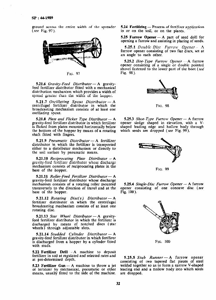
ground across the entire width of the spreader (see Fig. 97).
FIG. 97
521.6 Gravity-Feed Distributor - A gravity- feed fertilizer distributor fitted with a mechanical distribution mechanism which provides a width of spread greater than the width of the hopper.
5.21.7 Oscillating Spout Distributor - A centrifugal fertilizer distributor in which the broadcasting mechanism consists of at least one oscillating spout.
521.8 Plate and Flicker Type Distributor - A gravity-feed fertilizer distributor in which fertilizer is flicked from plates mounted horizontally below the bottom of the hopper by means of a rotating shaft fitted with fingers.
5.21.9 Pneumatic Distributor - A fertilizer distributor in which the fertilizer is transported either to a distributor mechanism or directly to the soil surface by pneumatic means.
5.21.10 Reciprocating Plate Distributor - A gravity-feed fertilizer distributor whose discharge mechanism consists of reciprocating plates in the base of the hopper.
521.11 Roller-Feed Fertilizer Distributor - A gravity-feed fertilizer distributor whose discharge mechanism consists of a rotating roller mounted transversely to the direction of travel and at the base of the hopper.
5.21.12 Rotating Disc(s) Distributor - A fertilizer distributor in which the centrifugal broadcasting machanism consists of at least one rotating disc.
5.21.13 Star Wheel Distributor - A gravity- feed fertilizer distributor in which the fertilizer is discharged by means of notched discs (star wheels) through adjustable slots.
5.21.14 Studded Cylinder Distributor - A gravity-feed fertilizer distributor in which fertilizer is discharged from a hopper by a cylinder fitted with studs.
5.22 Fertilizer Drill - A machine to deposit fertilizer in soil at regulated and selected rates and at predetermined depth.
5.23 Fertilizer Gun- A machine to throw a jet of fertilizer by mechanical, pneumatic or other means, usually fitted to the side of the machine.
5.24 Fertilizing - Process of fertilizer application in or on the soil, or on the plants.
5.25 Furrow Opener - A part of seed drill for opening a furrow and assisting in placing of seeds.
5.25.1 Double-Disc Furrow Opener - A furrow opener consisting of two flat discs, set at an angle to each other.
5.25.2 Hoe-Type Furrow Opener - A furrow opener consisting of a single or double pointed shovel fastened to the lower part of the boot (see’ Fig. 98).
FIG. 98
5.25.3 Shoe-Type Furrow Opener - A furrow opener sledge shaped in elevation, with a V- shaped leading edge and hollow body through which seeds are dropped (see Fig. 99).
FIG: 99
5.25.4 Single-Disc Furrow Opener - A furrow opener consisting of one concave disc (see Fig. 100 ).
FIG. 100
5.25.5 Stub Runner-A furrow opener consisting of two welded together so leading end and a are dropped.
tapered flat pieces of steel as to form a narrow V-shaped hollow body into which seeds
32
SP : 44-1989
5.26 Furrow Planting - Planting in the bottom of furrows.
5.27 Gaseous Fertilizer Distributor - A machine for applying mineral fertilizer in gaseous form which injects the fertilizer under pressure into the ground (see Fig. 101).
. --. .
FIG. 101
5.28 Hill Dropping - The process of placing seeds in small groups at regular intervals along straight parallel furrows and covering the seeds with soil so as to get assurance that there will be at least one plant from each spot where the group of seeds are placed.
5.29 Lime Spreader - A machine of large hopper capacity able to distribute heavy dressings of lime and similar materials at selected rates on the surface of the soil.
5.30 Liquid Fertilizer Distributor - A machine for applying mineral fertilizer in liquid form which either spreads the fertilizer on the surface of the ground or injects it into the soil.
5.31 Manure Application - Process of spreading manure on the soil and, in some cases, mixing it with the soil.
5.32 Metering Feed Mechanism - The mechanism of a seed drill, planter or fertilizer drill which delivers seeds or fertilizers from the hopper at selected rates.
5.32.1 Agitator-Feed Mechanism - A feed mechanism in which an agitator wheel maintains the flow of seed through an adjustable aperture (see Fig. 102 ).
FIG. 102
5.32.2 Auger-Feed Mechanism - A feed and/or distributing mechanism consisting of an auger which causes a substance to flow evenly.
5.32.3 Brush-Feed Mechanism - A feed mechanism in which a rotating brush regulates the flow of seed from the hopper (see Fig. 103).
FIG. 103
5.32.4 Cell-Feed Mechanism - A feed mechanism in which seeds are collected and delivered by a series of equally spaced cells (apertures or indentations ) on the periphery of a circular plate or wheel (see Fig. 104).
FIG. 104
33
SP : 44-1989
5.32.5 Cup-Feed Mechanism -A feed mechanism consisting of cups or spoons on the periphery of a vertical rotating disc which picks up seeds from the hopper and delivers them into a seed tube (see Fig. 105).
FIG. 105
5.32.6 Fluted-Feed Roller - A seed metering device with adjustable fluted roller to collect and deliver seeds into a seed tube (see Fig. 106).
FIG. 106
5.32.7 Internal Double Run - A seed metering mechanism in which the feed wheel is provided with fine and coarse ribbed flanges (see Fig. 107).
FIG. 107
5.32.8 Knock-Out Mechanism - A device which knocks out seeds from the cells or picker heads of the feed mechanism.
5.32.9 Picker- Wheel Mechanism - A feed mechanism for larger seeds like potato in which a vertical plate is provided with radially projected pick-up arms which lifts the seeds by means of jaws or pins and drops them by means of knock- out mechanism.
5.32.10 Plate-Feed Mechanism -A feed mechanism in which cells are provided on the periphery of a horizontal or slightly inclined plate (see Fig. 108).
FIG. 108
5.32.11 Seed- Taue Mechanism - A feed mechanism which delivers a pre-prepared tape of biodegradable material containing seeds at pre- determined intervals. Nutrients and/ or crop protection chemicals may be incorporated in the tape.
5.32.12 Seed- Wheel Mechanism - A feed mechanism consisting of a toothed wheel rotating in a horizontal plane and conveying the fertilizer through a feed gate below the star wheel (see Fig. 109 ).
FIG. 109
5.32.13 Studded-Roller Feed Mechanism - A feed mechanism with series of rollers having regular peripheral projections which meter seeds from a seed hopper (see Fig. I 10).
FIG. 110
5.33 No Tillage Planting - Direct planting in
534 Precision Drilling - Uniform placing of seeds in rows at a predetermined depth and seed rate.
535 Planter - A machine used for precision drilling, hill dropping or check-row planting.
535.1 Maize Planter - A machine for planting of maize seeds in the seed bed.
5.35.2 Sugarcane Planter - A machine used for planting sugarcane sets in the field.
5.35.3 Tuber Planter-A machine which deposits tubers in the soil in parallel rows and at a pre-determined spacing and depth, and subsequently cover them with soil.
5353.1 Automatic tuber planter - A tuber planter with automatic feed mechanism with or without hand or automatic compensator.
4
b)
cl
4
Automatic tuber planter with a belt or vertical cup feed - An automatic potato planter with a vertical flexible belt with cups mounted on it or a cup feed planter having one or several rows of cups per element.
Automatic tuber planter with horizontal belts - An automatic potato planter which selects potatoes on a horizontal strip formed by a row of sockets or two belts.
Automatic tuber planter with clamp feed mechanism - An automatic planter, the feed mechanism of which consists of a wheel fitted with automatically opening and shutting clamps which are held closed by spring pressure.
Automatic tuber planter with spiked wheel feed mechanism - An automatic planter, the feed mechanism of which consists of a wheel fitted with spikes which impale tubers to hold them until delivery.
5.35.3.2 Combine tuber planter - A machine to plant potatoes and apply fertilizer in one operation.
53533 Hand-feed tuber planter - A tuber [fn,xer, the planting element of which is fed by
a) Cup-feed tuber planter - A manually-fed tuber planter, the planting element of which consists of cups mounted on an endless chain.
b) Drop-tube tuber planter - A manually-fed tuber planter, the planting element of which consists of a drop-tube (see Fig. 111).
c) Notched-wheel tuber planter - A manually- fed tuber planter, the planting element of which consists of a vertical spacing wheel with self-emptying indentations or cells.
SP : 44-1989
FIG. 111
536 Pressure Bar - A spring or weight loaded bar which assists in penetration of the furrow opener.
537 Press Wheel - A wheel which compacts the soil and covers seeds in the furrow.
538 Ridge Fertilizer Attachment - A series of baffles fitted to a fertilizer distributor to direct fertilizer between the ridges.
539 Ridge Planting- Planting on ridges.
5.40 Row Marker - An attachment to a sowing machine to mark a line on the field to guide the position of extreme furrow opener during the next trip.
5.41 Seeding Attachment - An attachment provided in a cultivator for sowing seeds.
5.42 Seed Broadcasting Machine-A device or machine used for broadcasting seeds.
5.43 Seeder - A device for placing seeds on or in the soil.
5.44 Seed Drill- A machine to place seeds at uniform rate at selected depth and row spacing (see Fig. 112).
FIG. 112
35
SP : 44-1989
5.44.1 Agitator- Wheel Drill - A seed drill, the metering mechanism of which consists of agitator wheels. The seed rate is controlled mainly by varying the discharge apertures in the hopper base.
5.44.2 Cell- Wheel Spacing Drill - A spacing drill, the metering mechanism of which consists of a wheel with cells on its rim. The distance between seeds sown is controlled by varying the speed of rotation of the wheel or by selecting wheels with different cell spacings (see Fig. 113 ).
FIG. 113
0
5.44.3 Centrifugal-Feed Drill - A seed drill in which seeds are metered by centrifugal force.
5.44.4 Cup-Feed Seed Drill - A seed drill, the metering mechanism of which consists of discs fitted with cups on their periphery. The seed rate is controlled either by altering the size of the cups or by changing the speed of rotation of the discs.
5.44.5 Disc-Selector Drill - A spacing drill, the metering mechanism of which consists of a disc with notches mounted either vertically or inclined. A seed spacing is usually controlled by varying the speed at which the disc rotates orby selecting discs with different notch spaci’ngs (see Fig. 114 ).
5.44.6 Force-Feed Drill - A seed drill in which a positive metering mechanism comprises flutted rollers or internal double run wheels.
5.44.1 Gravity-Feed Seeder - A seeder in which the metering of seeds is done through gravity and positive metering is not possible.
5.44.8 Pneumatic-Feed Drill i A seed drill in which the metering of seeds is done by air stream at set spacing in continuous parallel rows.
5.44.9 Pneumatic-Spacing Drill - A spacing drill in which the placing of seeds is achieved pneumatically.
5.44.10 Pneumatic-Spacing Drill with Blower - A spacing drill in which distribution is effected by means of an air jet directed at the feed mechanism, which leaves only single seeds in the cells of the distributor mechanism. A seed spacing is usually controlled either by changing the speed of rotation or the spacing of the perforations of alternative seeding discs.
5.44.11 Pneumatic-Spacing Drill with Perforated Discs - A spacing drill in which the distribution is affected by providing a negative pressure to the metering mechanism which
FIG. 114
36
consists of a perforated disc., A seed spacing is usually controlled either by changing the speed of rotation of the disc, or by selecting discs into different hole spacings.
5.44.12 Pneumatic-Spacing Drill with Perforated Drums - A spacing drill in which distribution is affected by providing a negative pressure to the metering mechanism which consists of perforated drums. The seed spacing is usually controlled either by changing the speed of rotation of the drum or by selecting drums into different hole spacings.
5.44.13 Pneumatic-Spacing Drill with Perforated Rim - A spacing drill in which distribution is effected by providing a negative pressure to the metering mechanism which incorporates perforated rims. The seed spacing is usually controlled either by changing the speed of rotation or by altering the spacing of holes in the rim.
5.44.14 Seed-cum-Fertilizer Drill - A machine which drills seeds and fertilizer simultaneously in the same or different rows.
5.44.15 Spacing (Precision) Drill - A seed drill in which the metering mechanism distributes seeds singly or in groups at a set spacing in continuous parallel rows.
5.44.16 Spacing-Drill with Perforated Belt - A spacing drill in which the metering mechanism consists of a perforated belt. The spacings are adjusted by varying the belt speed or by selecting belts with differently spaced perforations (see Fig. 115 ).
5.44.11 Studded-Roller Drill- A seed drill, the metering mechanism of which consists of studded rollers. The seed rate is controlled by varying the speed of the rotating shaft.
5.45 Seed Tube-A tube which carries seeds from the metering device to the boot.
5.46 Solid Mineral Fertilizer Application Equipment - A machine which distributes solid mineral fertilizers in pre-determined quantities.
54: ,%,Grg -The process of placing seeds in
SP : 44-1989
5.48 Spreading Rotor - A rotating auger, disc, or series of toothed or paddle shaped blades at the rear of a manure spreader which spreads the manure.
5.49 Transplanter - A machine which sets seedlings into the ground in rows. The spacing between the seedlings is adjustable (see Fig. 116).
5.49.1 Clamp Type Transplanter - A transplanter, the planting mechanism of which consists of plates which carry clamping devices to hold seedlings.
5.49.2 Clamp with Disc Transplanter-A transplanter with a clamp holder used in association with discs.
5.49.3 Clamp with Tipping Share Transplanter - A transplanter with a tipping share fitted with a clamp.
5.49.4 Flexible Disc Transplanter - A transplanter, the planting element of which consists of flexible discs.
5.50 Transplanting - The process of planting seedlings in prepared seed beds.
6. INTERCULTIVATION EQUIPMENT
6.1 Cultivator - An implement for inter- cultivation with laterally adjustable tines or discs to work between crop rows. This can be used for seed bed preparation and for sowing with seeding attachment. The tine may have provision for vertical adjustments also.
6.1.1 Disc Cultivator - A cultivator fitted with discs.
6.1.2 Rotary Cultivator - A cultivator with tines or blades mounted on a power-driven horizontal shaft( s ) (see Fig. 117 ).
6.1.3 Tine Cultivator - A cultivator fitted with tines having shovels (see Fig. 118 ).
6.2 Cultivator Point - A replaceable soil working part attached to the lower end of the cultivator tines such as shovel and sweep.
6.2.1 Shovel- A soil working element with one or both end point. The later is known as reversible shovel.
FIG. 115
37
SP : 44-1989
FIG. II6
FIG. 117
FIG. 118
6.2.2 Sweep - A two-winged cutting point which cuts the soil in a horizontal direction under the surface.
6.3 Cultivator Tine -- A member cultivator point to main frame.
6.3.1 Rigid Tine- A cultivator does not deflect during work.
6.3.2 Spring-Loaded Tine - A
connecting
tine which
rigid tine hinged to the frame and loaded with one or more springs to enable it to swing on encountering an obstacle.
38
6.3.3 Spring Tine - A cultivator tine made of spring steel which can deflect when an obstacle is encountered in the soil.
6.4 Hoe - A hand tool with blade( s), tine( s) and sometime with disc(s) attached to a frame used for inter-cultivation of row crops.
6.4.1 Hand-Hoe - A hand operated hoe (see Fig. 119).
FIG. 119
6.4.2 Rotary Hoe - A hoe with curved pointed spikes rigidly attached to horizontal shaft.
6.4.3 Wheel Hoe - A hoe with one or two wheels.
6.5 Khurpi - A hand tool comprising a blade and a short handle used for loosening the soil, weeding and earthening up (see Fig. 120).
FIG. 120
6.6 Kodali - A hand tool comprising a narrow blade and a wooden handle used for loosening and cutting the soil (see Fig. 121).
6.7 Paddy Weeder - An equipment used to uproot the weeds in paddy crop planted in line (see Fig. 122 ).
6.7.1 Float (Sleigh)- A component in front of the weeding roll which ensures an easy sliding motion during operation through better floatation of the weeder.
SP : 44-1989
4ztf . FIG. 121
6.7.2 Frame- The part that holds float, and front and rear weeding rolls in position and to which the yoke of the handle is attached.
6.7.3 Weeding Roll - A revolving assembly with finger-like projections or tines which performs the operations of weeding and submerging the weeds in water.
6.8 Rotary Weeder - A ground-driven implement with straight or curved spikes mounted on disc rims for destroying weeds and breaking the soil surface.
6.9 Shovel- A hand tool comprising a narrow blade and a wooden handle having a grip at the rear for digging, scooping and throwing the soil (see Fig. 123 ).
6.10 Spade (Pow&)- A hand tool comprising a broad blade and a wooden handle used for loosening, cutting, earthing, dressing and removing the soil (see Fig. 124).
7. IRRIGATION EQUIPMENT
7.1 Adapter- A device used in sprinkler system as a fitting to connect two variable pipes of different sizes.
7.2 Application Rate - Rate at which the water is applied to a given area, usually expressed in depth of water per hour.
7.3 BaffIes- Vanes, guides, grids, grating or similar devices placed in a conduit to check, deflect or regulate flow.
7.4 Basin Irrigation-The application of water by flooding within areas of approximately level land surrounded by levees. Basins may vary in size from a few square feet to several acres.
7.5 Border Irrigation -The application of water to strips marked by levels 3 to 30 metres apart. The soil is essentially level between levels on even topography with a gentle slope so that the water forms a sheet over the whole area.
7.6 Canillarv CaDacitv - The maximum amount of cap\llary” watkr remaining in soil gravitational water has drained away.
after the
7.7 Capillary Conductivity - Capacity of partially saturated soils to transmit water, measured at the ratio of water flow velocity to the driving force. As soil becomes more saturated, capillary conductivity approaches the hydraulic conductivity.
7.8 Capillary Fringe - A zone just above the water table (Tero gauge pressure) that remains almost saturated. (The extent and the degree of definition of the capillary fringe depends upon the size-distribution of pores ).
7.9 Capillary Moisture - Water held in the soil pores by force of surface tension as a continuous film around the soil particles.
7.10 Capillary Potential - The energy required per unit mass to move water against the capillary field forces in the soil from a free water surface to any point in the soil.
7.11 Capillary Pressure Head - Head water that rises by surface tension above a free water surface in the soil. Also called capillary rise.
7.12 Capillary Soil Moisture - Moisture in soil held by surface tension forces against the force of gravity.
7.13 Capillary Zone- Soil zone above water level up to a limit in which pores become filled as a result of surface tension.
7.14 Check Irrigation- Application of a comparatively large stream of water in level plots surrounded by levees.
7.15 Conduit - Any open or closed channel intended for the conveyance of water.
7.16 Confined Water - Underground water, constrained b is under t*
an overlying confining bed, which suf icient pressure to rise above the
bottom of the confining bed.
7.17 Consumptive Use-The water used by plants in transpiration and growth plus water vapour loss from adjacent soil or snow or from intercepted precipitation in any specified time. Usually expressed as equivalent depth of free water per unit of time,
7.18 Continuous Flow Irrigation - System of irrigation water delivery where each irrigator receives his allotted quantity of water at a continuous rate.
7.19 Contour Basin-Basin made by levees or borders following the contours of the land.
7.20 Contour Ditch-Irrigation ditch laid out approximately on the contour.
7.21 Contour Flooding - Method of irrigating by flooding from contour ditches.
7.22 Contour Furrows - Furrows ploughed on the contour on pasture or range land to prevent
39
b FIG. 123
FIG. 124
soil loss and allow water to penetrate into the soil. Also furrows are laid out on the contour for irrigation purposes.
7.23 Contracted Weir - A measuring notch which has sides designed to produce a contraction in the cross-sectional width of the overflowing water.
7.24 ControI Structure - Water regulating structure, usually for gravity flow systems.
7.25 Corrugation Irrigation - Application of water in small furrows running down from the head ditch. The furrow guides the water but some over-topping may occur.
7.26 Cross- Pipe fitting with four outlets or connections each 90” apart in sprinkler system.
7.27 Cubic Metre Per Second - A flow of water equivalent to a stream one metre wide and one metre deep flowing at a velocity of one metre per second.
7.28 Cumulative Infiltration - Summation of the depth of water absorbed by a soil in a specified elapsed time with reference to the time of initial water application.
7.29 Deep Percolation - Water which percolates downward below the root zone and cannot be used by plants.
7.30 Depth of Irrigation - Depth of soil to be brought to field capacity.
SP : 44-1989
7.31 Distributory - Smaller conduit taking water from a canal for delivery to farms; any system of secondary conduits; river channel flowing away from the main stream and not rejoining it, as contrasted to a tribufary.
7.32 Distribution Efficiency - Measure of the uniformity of irrigation water distribution over a field.
7.33 Diversion Duty of Water-The irrigation water diverted at the intake of a canal system, usually expressed in depth or the irrigable area under the system.
7.34 Diversion Box - Structure built into a canal or ditch for dividing the water into pre- determined portions and diverting it into other canals or ditches.
7.35 Drip Irrigation-This is a method of application of water directly to the land surface or below the surface near the plant root in small quantities but continuously. Water application is accomplished through an extensive network of small diameter pipes fitted with emitters or drippers.
7.36 Field Capacity-The amount of water retained in a soil against a force of gravity at any specified time (about 24 to 36 hours) after flooding. It is approximated by moisture equivalent and one-third atmosphere percentage.
7.37 Field Ditch-A smaller ditch constructed within a field either for irrigation or for drainage.
7.38 Flooding-The water is released from field ditches and allowed to flood over the land.
7.39 Foot Valve - Check valve opening upwards installed at the inlet end of the suction pipe to retain water in the pump for priming.
7.40 Furrow Irrigation - This method consists in making the land into ridges and furrows, and irrigating the area through furrows.
7.41 Gate - Structure or device in irrigation for controlling the rate of flow into or from a canal or ditch.
7.42 Gravity Irrigation - Irrigation in which the water is not pumped but flows by gravity including sprinkler system.
7.43’ Hydraulic Ram - An automatic device with which the energy of a quantity of water with small head is used to lift proportionate quantity of this water to a greater height. It works on the principle of water hammer.
7.44 Infiltration -The downward entry of water into the soil.
7.45 Infiltration Rate-The maximum rate at which a soil, in a given condition at a given time can absorb water* impounded on the surface at a
*Also the maximum rate at which a soil will absorb water.
41
SP : 44-1989
shallow depth when adequate precautions are taken regarding border or fringe effects. Defiiled as the volume of water passing into the soil per unit of area of velocity P
er @t of time. It has the dimensions LT 1.
7.46 Infiltrometer - A device for measuring the rate of entry of fluid into a porous body when applied uniformaly over the area, for example, watir into soil.
7.47 Irrigatable Area - Area capable of being irrigated, principally as regards quality and elevation of land.
7.48 Irrigation - Artificial application of water to soil for the purpose of supplying moisture essential to plan! growth.
7.49 Irrigation Effkiency - The ratio of the water consumed by crops of an irrigated farm or project to the water diverted from a river or other natural water source into the farm or project canals.
7.50 Irrigation Frequency - Time interval between irrigations.
7.51 Irrigation Methods- The manner in which water is artificially applied to an area.
7.52 Irrigation Stream - Flow used for irrigation of a particular tract of land; flow of water distributed at a single irrigation or that in a single farm lateral.
7.53 Lift Magnification -The ratio of the delivery head to the intake head in case of hydraulic ram. It is also known as magnification factor.
7.54 Moisture Content - Percentage by weight of moisture based on wet weight in a sample.
7.55 Moisture Density - Mass of water per unit volume. When expressed in grams per cubic centimetre, it is numerically equal to the percentage of total space occupied by the water.
7.56 Moisture Penetration - Depth to which moisture penetrates following irrigation or rainfall before the rate of downward movement becomes negligible.
7.57 Moisture Percentage - The percentage of water in soil and plant usually expressed on a dry- weight basis. If otherwise expressed, the basis should be stated.
7.58 Moisture Tension - The equivalent negative gauge pressure or suction in the soil moisture. Soil moisture tension is equal to the equivalent negative or gauge pressure to which water must be subjected in order to be in hydraulic equilibrium through a porous permeable wall or membrane with the water in the soil.
7.59 Rotation Irrigation System - System of irrigation in which a number of irrigators rotate a
portion of the entire flow in turn for a limited period of time.
7.60 Sprinkler Irrigation - The application of water to the soil by spraying through nozzle.
7.61 Sprinkler Systems - All the equipments required to apply water to a given area from the source of water to sprinkler nozzle.
7.61.1 Boom Type - An elevated, cantilevered sprinkler( s ) mounted on a central stand. The sprinkler boom rotates about a central pivot.
7.61.2 Farm System-System which will properly distribute the required amount of water to the entire farm.
7.61.3 Field System-That part of a farm system which covers one field or area for which it is designed.
7.61.4 Hand Move-Method of moving the spnnkler system by uncoupling and picking up the pipes manually requiring no special tools. This includes systems in which lateral pipes are loaded and unloaded manually from racks or trailers used to move the pipes from one lateral setting to another.
7.61.5 Mechanized - System which is moved either by engine power, tractor power, water power or hand power on wheels or skids. Generally considered as any type of system that can be moved without carrying manually.
7.61.6 Permanent - System consisting of permanent underground piping with either permanent risers for sprinklers or quick coupling valves in such a manner that sprinklers may be attached.
7.61.7 Self-Propelled System - Portable powered system which moves continuously when in operation. May rotate about a pivot in the centre of field or move laterally across the field in a predetermined direction.
7.61.8 Semi-Portable - Systems designed with permanent pumping units and mains but with portable sprinkler laterals.
7.61.9 Side-Roll System - System mounted on wheels, usually employing the lateral pipeline as an axle, where the lateral is moved at right angles to the mainline by rotating the pipeline either by hand or by engine power.
7.61.10 Solid Set - System, either permanent or portable, which covers the complete field with pipes and sprinklers in such a manner that a!1 the field can be irrigated without moving any of the system.
7.61.11 Towed System - System where lateral lines are mounted on wheels, casters, sleds or skids and are pulled or towed in the field to be irrigated in a direction approximately parallel to the lateral.
42
SP : 44-1989
7.62 Sub-Irrigation - Application of water by percolating from wide-spaced furrows to an impermeable layer in the soil with a temporary rise of water table to wet the entire soil body. This practice requires an impervious sub-soil layer, a porous surface soil and a uniform topography of moderate slope.
7.63 Supplemental Irrigation - Irrigation which is used primarily to supplement rainfall.
7.64 Surface Irrigation ~ Irrigation where the soil surface is used as a conduit as in furrow and border irrigation.
7.65 Surface Water - Water stored on or flowing over the surface of the soil.
7.66 Total Suction Head -The vertical head, in metres, from the water level to the centre line of the pump plus velocity head, entrance losses and friction losses in suction line including foot valves, striners, and fittings.
7.67 Transpiration Ratio - Ratio of weight of water absorbed and transpired by the plant to the weight of the dry matter produced. Evaporation from soil not included.
7.68 Trapewidal Weir - A liquid flow measuring device with ,a trapezoidal notch.
7.69 Triangular Weir - A contracted measuring weir notch with sides that torm an angle with its apex downward.
7.70 Trickle Irrigation - see 7.35.
7.71 Unavailable Water - Soil water held so firmly by adhesion.
7.72 Unsaturated Flow-The movement of water in a soil which is not filled to its field capacity with water.
7.73 Water Application Efficiency - The ratio of water stored in soil root zone to the amount of water delivered at the farm.
7.74 Water Level - Water surface; also its elevation above any datum; gauge height; stage.
7.75 Water Resources- Supply of water in a given area or watershed, usually interpreted in terms of availability of surface or underground water.
7.76 Water Table - The upper surface of ground water, locus of points in soil water at which the hydraulic pressure is e’qual to atmospheric pressure.
7.77 Wilting Point -The percentage of water in soil ( based on dry weight soil) when permanent wilting of plants occurs.
7.78 Zone of Aeration - Subsurface zone above the water table in which the soil or permeable rock is not saturated.
7.79 Zone of Saturation - Layer of earth (may be both soil and underlying strata) containing gravitational or free water.
8. HORTICULTURAL EQUIPMENT
8.1 Bill Hook - A hand tool used for lopping of branches and cleaning in plantation and estate. It may have single edge or double edge (see Fig. 125).
G=- FIG. 125
8.2 Budding and Grafting Knife - A knife used for budding and grafting purposes (see Fig. 126).
8.3 Budding Knife - A knife to remove the bud from the scion, to cut the stock, slit and raise the bark to insert the bud (see Fig. 127).
h OUTER HANDLE SCALES
INNER HANDLE SCALES y LSPRING A
CUTTING EDGE7 FNAIL GROOVE /CUTTING EDGE
t -
\NAlL GROOVE BUDDING BLADE HANDLE GRAFTING BLADE
FIG. 126
43
SP : 44-1989
FIG. 127
FIG. 131 8.4 Budding Tape-Tape used in holding the buds in their position after budding operation.
8.5 Dah - A metal piece with handle used for cutting trees and clearing jungle growth (see Fig. 128 ).
FIG. 128
8.6 Digging Fork - Fork with long handle used ’ for digging (see Fig. 129).
FIG. 129
8.7 Draining and Tapping Knife-A blade attached to a wooden handle and is designed to have a V-shaped cutting edge to make narrow channels in the bark of rubber trees to open the latex cells and to facilitate easy tappling and draining of latex from the tree.
8.8 Forester’s Shear - A shear for pruning thicker stock.
8.9 Garden Fork - A hand tool with handle and prongs placed in line of handle or perpendicular to it used for loosening the soil (see Fig. 130).
B FIG. 130
8.10 Garden Hatchet - An axe-like tool with one side sharp edge having long handle used for cutting branches (see Fig. 13 1).
8.11 Garden R&e-A hand tool used for collecting uprooted weeds, breaking clods and to some extent levelling of seed bed in the garden (see Fig. 132).
FIG. 132
8.12 Garden Trowel - A transplanting trowel used for digging and lifting small plants (see Fig. 133).
FIG. 133
8.13 Grafting Knife-A knife to cut the wood from scion and to insert the same in the stock (see Fig. 134).
FIG. 134
8.14 Grass Shear - A scissor-like tool used for cutting the grass (see Fig. 135).
8.15 Grass Sword-A thin metal strip with a handle having one side cutting edge used for
SP : 441989
FIG. 135
cutting the grass normally in bending ( see Fig. 136).
position
FIG. 136
8.16 Hand Cultivator - A hand tool with prongs handle used for cohecting the weeds and
breaking the clods in the garden (see Fig. 137).
G?=
FIG. 137
8.17 Hand Dibbler - A peg type tool used for making holes in soil for placing the seeds (see Fig. 138).
FIG. 138
8.18 Hedge Shear - A scissor-like tool used for pruning of hedges and twigs (see Fig. 139).
FIG. 139
8.19 Hoe and Rake Combined-A hand tool having one side rake and opposite side hoe (see Fig. 140).
FIG. 140
8.20 Lawn Mover - A machine where the cutting means operate in the plane of the ground and which uses the ground to determine the height of cut by means of wheels, air cushion or skides, etc. (see Fig. 141).
FIG. 141
8.20.1 Attachment - Any assembly or component connected to a power unit for the purpose of accomplishing work such as cutting grass.
8.20.2 Blade Tip Circle-The path described by the outermost point of the cutting means as it rotates about its shaft axis.
8.20.3 Braking System - A combination of one or more brakes and the related means of operation and control.
8.20.4 Control- A means or device which will control the operation of the mower or any specific operating function thereof.
8.20.5 Cutting Means (Blade) - The mechanism used to provide the cutting action for the width of cut of a lawn mower.
8.20.6 Cutting Means Enclosure - The part or assembly which provides the protective means around the cutting means.
45
SP : 441989
8.20.7 Cutting Positions - Any designated height adjustment (setting) of the cutting means where it remains operative.
8.20.8 Cutting Width- The width of cut measured across the cutting means at right angles to the direction of travel and calculated from the dimensions of the cutting means or the diameter(s) of the blade tip circle(s).
8.20.9 Cylinder (Reel) Mower - A grass- cutting machine with one or more blades rotating about a horizontal axis to provide a shearing action with a stationary cutter bar or knife.
8.20.10 Automatic Declutching Control - A control designed so that it will automatically interrupt power to a drive when the operator’s actuating force is removed.
8.20.11 Discharge Chute - xtension of the discharge opening generally L.,bu to control the discharge of material from the cutting means.
8.20.12 Discharge Opening- A gap or opening in the cutting means enclosure through which grass may be discharged.
8.20.13 Edger - A power grass-cutting machine suitable for cutting lawn and soil, usually in a vertical plane.
8.20.14 Flail Mower - A grass-cutting machine which’utilizes a power source to rotate a horizontal shaft with blade. Cutting action is accomplished by impact with rotating blades.
8.20.15 Grass Catcher-A part or combi- nation of parts which prcvide a means for collect- ing grass clippings or debris.
8.20.16 Guard- A means such as bar, barrier, structural component, etc, that restricts an inadvertent access to a hazardous area.
8.20.17 Lawn Trimmer-A power grass- cutting machine where the operator determines, the plane of operation of the cutting means and the height of cut, possibly assisted by a wheel or skid, etc.
8.20.18 Mower Attachment - A cutting means designed to be easily detached from the vehicle generally to allow vehicle to be used without the mower or with other attachments.
8.20.19 Mulching Mower - A rotary mower having a fixed or optional configuration without openings in the mower housing above the plane of the blade for the discharge of grass clippings.
8.20.20 Pedestrian-Controlled Mower - A grass-cutting machine, either pushed or self- propelled, normally controlled by the operator walking behind the unit.
8.20.21 Power Lawn Mower - A grass-cutting machine which is powered by mechanical means or electric motor (see Fig. 142).
8.20.22 Ride-on (Riding) Machine; Lawn and Garden (Riding) Tractor - A self-propelled vehicle on which an operator rides which is generally intended for cutting grass. The cutting means may either be an integral part of the vehicle or suspended from or attached to the vehicle.
8.20.23 Safety Device - An installation designed to protect the operator or other persons, for example, shields, grass catching equipment, deflectors, covers for chains, belts, drive shafts, etc.
8.20.24 Shield-A part or an assembly that, unless displaced or removed, restricts access to or from a hazardous area.
8.20.25 Sickle Bar Mower - A cutting machine which utilizes a power source to operate a knife or knives to provide a shearing action with a stationary cutter bar or movable knife.
8.20.26 Sulky Type Unit - A walk behind power lawn mower which has been converted to a riding mower by the addition of an optional trailing device on which the operator rides.
8.20.27 Swing-Over Handle - A handle that pivots from one end of a walk-behind mower to the other end to allow reversing the direction of travel of the mower without turning the mower around.
8.20.28 Thrown Object Hazard - The potential for injury caused by object(s) propelled by the moving cutting means.
8.20.29 Towed Unit - Implement pulled from the drawbar of a propelling machine and usually equipped with wheels for transport.
8.20.30 Traction Drive - The means ( system ) used to transmit power from the power source to the ground drive means.
8.20.31 Transport Position - The designed state of the mower for propelled transport of the unit or position to which the cutting means is brought when transporting the mower.
8.21 Lopping tShear - A shear with long handle and smaller blade (see Fig. 143).
8.22 Orchard Ladder-Ladder used for facilitating picking of fruits, pruning, spraying and other common operations carried out in the gardens.
8.23 Pruning Knife - A folding knife with handle used for pruning of small plants (see Fig. 144).
8.24 Pruning Saw - A metal strip with serrated teeth and handle for cutting green stock (see Fig. 145 ).
8.25 Secateur - A scissor-like tool used for pruning the plants (see Fig. 146).
46
SP : 44-1989
GRASS REFLECTOR
BACK ROLLER
.
~
FIG. 143
FIG. 144
FIG. 142
FIG. 145
4----- SIZE OF THE SECATEUR
I
f SCREW ..Ni----Zl
L - PIVOT bANDLE / BLADE
FIG. 146
8.26 Transplanting Trowel -- A scoop-shaped tool with handle used for digging and lifting small plants without damaging the root zone for their transplanting ( see Fig. 147 ).
47
SP : 44-1989
4 8.29 Watering Can-A water holding container normally with perforated openings used for applying water to the plants preferably in a spray form (see Fig. 150).
FIG. 150 FIG. 147
8.27 Tree Pruner - A hand tool with long handle used for pruning of high tree (see Fig. 148).
LINK SOCKET
BODY
9. FORESTRY EQUIPMENT
9.1 Angle Transmission - Device for transmitting the power from the power transmission shaft to the saw blade.
9.2 Boring - The process of cutting with the saw chain at the nose (tip) of the guide bar in order to make a hole. This is also known as straight-in-cut [see Fig. 151 (A and B)].
FIG. 148
8.28 Trenching Hoe-A hand tool, having one side a miniature spade and opposite side kodali used for making small trenches in nurseries and gardens (see Fig. 149).
FIG. 149
FIG. 151(A)
FIG. 151(B)
9.3 Bucking-Cross cutting felled or uprooted trees or parts of trees, into lengths (see Fig. 152).
48
SP : 44-1989
FIG. 152
9.4 Bunching - Gathering and arranging trees or parts of trees in bunches to facilitate loading and transportation.
9.5 Cable Skidder-Skidder that uses winch cable(s) (rope) (usually with chokers) to assemble and hold its load.
9.6 Chain Brake-Device for stopping or locking the chain, activated manually or released automatically when kick-back occurs.
9.7 Chain Catcher - Device for restraining the chain if it breaks or degrooves.
9.8 Chain Guides- Plates or guides, fitted on one or both sides of the guide bar where the chain enters the groove, for assisting in guiding the chain between the sprocket and the guide bar.
9.9 Chain Oil Pump Adjuster - Device for adjusting the delivery of chain oil from the cham oil pump to the guide bar and the chain.
9.10 Chain Pitch-The arithmetic mean of the two distances between three adjacent rivets.
9.11 Chain Tension Adjuster - Device acting on the guide bar for adjusting the chain tension.
9.12 Chipper - Machine designed to chip trees or parts of trees.
9.13 Chipping - Converting logs or billets into small pieces for further processing.
9.14 Choke - Device for enriching the fuel air mixture in the carburettor, to aid starting.
9.15 Clam Bunk Skidder-Skidder that uses an integrally mounted loader to assemble the load into an inverted grapple or top-opening jaws to hold its load.
9.16 Clearing - Removing unwanted logging residues, shrubs, trees and stumps.
49
9.17 Clutch-Device for engaging and disengaging a driven member to and from a rotating source of power.
9.18 Clutch Cover - Protective cover on the clutch and the sprocket.
9.19 Conversion - Transformation of natural timber into any kind of product.
9.20 Debarker - Machine designed to remove bark.
9.21 Debarking-Removing bark from trees or parts of trees (see Fig. 153 ).
9.22 Debranching - Removing branches from trees or parts of trees.
9.23 Delimber - Machine designed to remove branches from trees.
FIG. 153
SP : 44-1989
9.24 Delimbing -See 9.22 and Fig. 154.
FIG. 154
9.25 Decompression Valve - Device for lowering the compression in the cylinder to aid starting.
9.26 Feller - Self-propelled machine designed to fell standing trees.
9.27 Feller Buncher - Self-propelled machine designed to fell standing trees and arrange them in bunches on the ground.
9.28 Feller Forwarder - Self-propelled, self- loading machine designed to fell standing trees and move the felled trees by carrying them.
9.29 Feller Skidder - Self-propelled machine designed to fell standing trees and transport them by dragging.
9.30 Felling - Cutting a standing stem above the root system.
9.31 Felling Sights - Marks on the chain saw to aid felling a tree in a desired direction.
9.32 Forwarder - Self-propelled machine, usually self-loading designed to move trees or parts of trees by carrying them completely off the ground. Normally forwarders are used for off- road transportation,
9.33 Forwarding - Moving trees or parts of trees out of the forest by carrying them.
9.34 Front Handle - Support handle located at or towards the front of the engine housing.
9.35 Front Hand Guard- Guard between the front handle and chain for protecting the hand from injuries and aiding in control of the saw if the hand slips off the handle. This guard is often used to activate the chain brake.
9.36 Guide Bar-The part that supports and guides the saw chain.
9.37 Guide Bar Cover - Removable device for covering the guide bar and chain when the saw is not being used.
9.38 Grapple Skidder - Skidder that uses a suspended grapple or bottom opening jaws to assemble and hold its load.
9.39 Handles - Support handles for manoeuvring the saw (see Fig. 155).
9.40 Harness - Adjustable straps of leather, plastic or other suitable material by means of which the saw is suspended from the operator.
9.41 Harvester - A self-propelled multi-function machine which combines felling with other processing functions.
9.42 Heated Handle - Handle equipped with a device which allows it to be heated, for example, by exhaust gases or electricity.
9.43 High Speed Mixer Adjuster - Device, normally a screw, for adjusting the fuel delivery at full throttle.
9.44 Hip Pad-Strap or pad of leather, plastic or other suitable material fastened either to the saw or to the harness, to cushion the operator from impact and to reduce transmission of vibration.
9.45 Idle Speed Adjuster - Device, normally a screw, acting on the throttle, for adjusting the idle speed.
9.46 Ignition Switch - Device for connecting and disconnecting the ignition system and thus allowing the engine to be started or stopped.
9.47 Kick-Back (Brush Saw) - Uncontrolled (sudden and accidental) sideways or backward motion of the saw blade which may occur when it contacts an object such as a sampling, tree stump, etc, especially when the cutting force is directed towards the operator.
9.48 Kick-Back (Chain Saw) - Uncontrolled (sudden and accidental) upward and/or backward motion of the guide bar which may occur when the saw chain at the nose (tip) of the guide bar contacts an object such as a log or branch or when the wood closes in and pinches the saw chain in the cut.
9.49 Loading - Picking up trees or parts of trees from the ground or from a vehicle and transferring them to and piling them on another vehicle.
9.50 Log Loader - Self-propelled machine, with grapple and supporting structure, designed to pick up and discharge trees or parts of trees for the purpose of piling or loading.
9.51 Logging - Operation comprising felling of trees, limbing, bucking and transportation of the resulting product out of the forest.
9.52 Lopping-Cutting of branches from a standing tree.
9.53 Low Speed Mixer Adjuster-Device, 9.62 Processor - A multi-function machine normally a screw, for adjusting the fuel delivery at idling speed.
which does not fell trees but performs two or more subsequent functions.
9.54 Manual Oiler - Manually operated pump delivering oil to the chain.
9.63 Pruning - Removing of live or dead branches or multiple leaders, from standing trees
9.55 Muffler Silencer - Device for reducing for the improvement of the tree or its timber.
engine exhaust noise and directing the exhaust 9.64 Quick Release Mechanism - Device gases. enabling the operator to free himself quickly from
9.56 Mulching - Applying a layer of organic the saw in case of emergency.
matter on the surface of the soil. 9.65 Rear-Handle - Support handle located at
9.57 Nose Guard-Device, covering the nose or towards the rear of the engine housing.
area of the guide bar, for reducing the incidence or severity of kick-back.
9.66 Rear Hand Guard - Extension on the lower part of the rear handle for protecting the hand
9.58 On-Off Switch - Device for connecting and from the chain if it breaks or degrooves.
disconnecting the electric current and thus allowing the motor to be started or stopped. 9.67 Rim Sprocket-Chain drive wheel with
9.59 Piling - Depositing trees or parts of trees in teeth, with rims on which the side and cutter links run.
orderly piles.
9.60 Power Transmission Shaft - Shaft inside 9.68 Saw Blade - Metal disc with peripheral
the shaft tube for transmitting the power from the cutting teeth.
engine to the saw blade. 9.69 Saw Blade Cover - Removable cover
9.61 Primer - Device for supplying extra fuel to aid starting.
completely shielding the saw blade teeth when the saw is not in use.
51
SP : 44-1989
9.70 Saw Blade Guard - Device covering the rear part of the saw blade in order to protect the operator.
9.71 Saw Chain- Chain serving as a cutting tool, usually consisting of drive links, cutters and side links, held together by rivets.
9.72 Scarifying - Preparing a site for regeneration by scaring the ground surface to penetrate the covering material and expose the soil underneath.
9.73 Shaft Tube-Part of the saw body that provides a casing for the power transmission shaft.
9.74 Skidder - Self-propelled machine designed to transport trees or parts of trees by dragging.
9.75 Skidding -Transporting trees or parts of trees by dragging.
9.76 Slasher - Machine designed to cross cut felled trees to pre-determined lengths.
9.77 Slashing - See 9.3.
9.78 Sliding - Downward transport&ion of timber along a pre-determined path.
9.79 Sorting - Collecting similar items (for example, pieces of timber after bucking).
9.80 Spiked Bumper-Device, fitted in front of the guide bar mounting point, acting as a pivot when in contact with a tree or log.
9.81 Splitting - Dividing trees or parts of trees longitudinally into pieces (see Fig. 156).
FIG. 156
9.82 Spur Sprocket - Chain drive wheel with teeth in which the drive links run, and the side and cutter links are supported.
9.83 Stacking-Piling of timber in specified sizes.
9.84 Stump Lowering - Reducing the height of stumps.
9.85 Suspension Eyelet - Ring or other fitting, fixed to the saw near its centre of gravity, to which the harness is attached (see Fig. 155).
9.86 Throttle Lock - Device for temporarily setting the throttle a partially open position, to aid. starting.
9.87 Throttle Trigger - Device, usually a lever, activated by the operator’s hand or finger, for controlling the engine speed.
9.88 Throttle Trigger Lockout - Device that prevents the accidental operation of the throttle trigger until manually released.
9.89 Topping - Cutting off the top of a tree at a pre-determined height.
9.90 Uprooting - Removing trees with the root systems from the ground.
9.91 Wrap Round Handle - Special type of front handle allowing the saw to be used also in the right-hand side up ( RSU) position.
9.92 Yarder - Machine designed to perform cable logging with the use of a tower which may be integral to the machine or a separate structure.
9.93 Yarding -The operation of initial haul to a collecting point.
10. CROP PROTECTION EQUIPMENT
10.1 Agitation - An operation which produces and maintains uniform spray mixture in the tank, and in the case of dusts or granules to facilitate their flow from the hopper.
10.1.1 Hydraulic Agitation - Agitation of the spray mixture by using an auxiliary pump flow or a partial flow of the main pump.
10.1.2 Mechanical Agitation - Agitation of the spray mixture, dust or granules by means of mechanically-operated stirrer inside the tank or hopper.
10.1.3 Pneumatic Agitation - Agitation of the spray mixture, dust or granules inside the tank or hopper using an air flow.
10.2 Agitator - A device used for agitation (see 10.1).
10.2.1 Hydraulic Agitator - A device used for hydraulic agitation (see 10.1.1).
10.2.2 Mechanical Agitaror - A device used for mechanical agitation (see 10.1.2).
10.2.3 Pneumatic Agitator - A device used for pneumatic agitation (see lOi1.3).
10.3 Air Compressor - An appliance for raising the pressure of air above that of the atmosphere.
10.4 Air Deflector-A device to alter the direction of the air flow.
10.5 Air Flow - Volume of air flowing by an appliance per unit of time.
10.6 Air Output - Volume of air discharged by an appliance per unit of time.
10.7 Anti-Drip Device-A device, which normally forms part of or is fitted within the nozzle, to instantly prevent any further flow or dripping from the’ nozzle after the spray boom has been shut-off.
10.8 Application Rate-The quantity of spray mixture, dust or granules distributed by an appliance per hectare.
10.9 Automatic Cut-Off Valve - An automatic device which closes when the pressure of the fluid or gas reaches pre-determined value.
10.10 Axial Flow Fan (Axial Flow Blower) - An appliance for producing an air flow parallel
to the blower shaft.
10.11 By-Pass- A device which allows all or part of the fluid delivered by the pump to be returned to the tank.
10.12 Centrifugal Fan ( Centrifugal Blower) - An appliance for producing an air flow at right
angles to the blower shaft.
IO.13 Collector Deflector - A device intended to collect and direct an air flow in a definite direction.
10.14 Cut-Off Device - A hand-operated mechanism situated between the delivery hose and the spray lance for controlling the flow of the liquid.
10.15 Droplet Size- The mean diameter of the droplet expressed in micrometres.
10.16 Duster- An appliance used for dusting (see 10.18).
10.16.1 Knapsack Duster - A duster which could be mounted on the back of the operator.
10.16.2 Mechanical Duster - An appliance used for mechanical dusting (see 10.18.2).
10.16.3 Pneumatic Duster - An appliance used for pneumatic dusting (see 10.18.3).
10.16.4 Rotary Duster - A duster with a hand- operated rotor usually carried in front or side of the operator.
10.17 Dust Hopper - Container for holding dust.
10.18 Dusting- Application of materials in the form of dust.
10.18.1 Electrostatic Dusting - Process where electrostatic forces are applied for the deposition of dust.
10.18.2 Mechanical Dusting - Distribution of dust by mechanical means.
SP : 44-1989
10.18.3 Pneumatic Dusting - Distribution of dust by means of flow of gas, usually air.
10.18.4 Wet Dusting - Method of treatment comprising the simultaneous emission of dust and a liquid spray.
10.19 Dust Nozzle - A device for directing dust in an air flow.
10.20 Fan-An appliance for producing an air flow by means of blades fixed to a rotating shaft.
10.21 Flame Gun-An appliance which produces a burning flame under pressure to control weeds, pests, etc.
10.22 Fumigator - An appliance to generate and distribute gases or smokes.
10.23 Granule Applicator - An appliance for applying materials in the form of granules.
10.24 Granule Hopper - Container for holding granules.
10.25 Granule Metering Mechanism - Part of a granule applicator which controls the flow of granules at desired application rate.
10.26 Granule Nozzle-A device for directing granules in an air flow.
10.27 Hydraulic Injector - A device using the velocity of a jet of liquid to produce a vacuum in a suction pipe for the purpose of filling a tank.
10.28 Injection - The act of forcing a fluid under pressure into another fluid or porous medium.
10.29 Liquid Output-Volume of liquid discharged by an appliance per unit of time.
10.30 Multi-Outlet Control Valve - A enabling the flow of the spray mixture directed to one or more outlets.
device to be
10.31 Nominal Spray Angle - Spray obtained at a reference pressure characterizes a given type of nozzle.
angle which
10.32 Non-Return Valve - An automatic device which permits the flow of a fluid in one direction only.
10.33 Nozzle Bar - Rigid or flexible tube fitted to the end supplying the nozzles with spray liquid.
10.34 Nozzle Boss-The leg on the spray boom (see 10.55) or spray lance (see 10.59) to which the nozzle body or nozzle cap is fitted.
10.35 Nozzle Parts
10.35.1 Anvil - A component of a deflector nozzle which deflects the spray liquid after its emission from the nozzle orifice.
10.35.2 Body -The main component into or on which the other components of the nozzle are fitted.
53
SP :44-1989
10.35.3 Cap - The component which retains the assembled parts’ in or on the body.
10.35.4 Disc - The disc shaped component containing the final orifice of a cone nozzle (see 10.64.2) or some type of fan nozzles (see 10.64.5).
10.35.5 Gasket - A compressible insert placed between the two surfaces to obtain a liquid- or gas-tight sealings.
10.35.6 Strainer - A component for separating foreign matter from the spray liquid.
10.35.7 Swirl Back Plate - Part of a particular type of turbulence nozzle which forms the rear part of the swirl chamber and the tangential liquid entry channels.
10.35.8. Swirl Chamber - The cavity between the nozzle disc and the swirl plate.
10.35.9 Swirl Plate-The part of the cone nozzle. ( see 10.64.2 ) which imparts rotation to the liquid passing through it. It is also known as swirl core.
10.35.10 Tip - The component containing the final orifice of a fan nozzle (see 10.64.5) or of some type of cone nozzle (see 10.64.2).
10.36 Nozzle Spacing - The distance between centre-to-centre of adjacent nozzles on a spray boom (see 10.55).
10.37 Overflow Pipe-A pipe through which excess fluid from a pump is by-passed by the action of a relief valve or pressure regulator.
10.38 Overhead Spraying - The spraying performed in the field on top of the crop.
10.39 Piston Displacement - The volume displaced by the piston during one stroke.
10.40 Plantation Spraying - The spraying performed vertically to cover the height of the plant or trees.
10.41 Pressure Chamber - A chamber with or without air pressurization to even out the fluctuations of the liquid pressure and induce uniform flow of liquid. It is also known as air vessel, air bottle and air chamber.
10.42 Pressure Pulsation Damper - A device for reducing pressure pulsations.
10.43 Pressure Regulator - An automatic device to control the pressure of a fluid or gas within a range of settings.
10.44 Pump
10.44.1 Centrifugal Pump - A non-volumetric pump in which the liquid energy is increased by one or more impellers.
10.44.2 Diaphragm Pump - A volumetric pump in which the flow of the liquid is achieved by the deformation of a diaphragm.
10.44.3 Gear Pump -A volumetric pump in which the flow of the liquid is achieved by gears.
10.44.4 Peristaltic Pump - A volumetric pump in which the flow of the liquid is achieved by the continuous progression of a flexible tube.
10.445 Piston Pump-A volumetric pump in which the flow of the liquid is achieved by the movement of a piston in a cylinder.
10.44.6 Roller Pump - A volumetric pump in which the flow of the liquid is achieved by the radial displacement of rollers placed in a rotor and in contact with an eccentric stator.
10.44.7 Vane Pump-A volumetric pump in which the flow of the liquid is achieved by the radial displacement or deformation of a vane placed or fixed in a rotor, and in contact with an eccentric stator.
10.44.8 Volumetric Pump - A pump in which the flow of the liquid is achieved by means of the variation in volume of one or more capacities which alternately sucks in and discharges the liquid.
10.45 Pump Output - Volume of liquid dis- charged by a pump per unit of time.
10.46 Quick-Acting Shut-Off Valve - A device enabling a spray system to be opened or closed instantly.
10.47 Pressure Relief Valve - An automatic device which opens when the pressure of ‘the fluid or gas reaches a predetermined value.
10.48 Safety Valve- An automatic valve which opens and relieves the pressure when it reaches a predetermined value thereby protecting the spray system and operator.
10.49 Seed Dresser-A machine to apply coating of protective chemical to seeds.
10.50 Shutter (Air Flow Control ) - A part of an appliance to control the flow of air.
10.51 Soil Injector - Appliance for injecting chemicals into soil.
10.52 Spray- The droplets produced by a nozzle.
10.52.1 Air-Assisted Spray - Spray which is carried wholly or partly by a stream or flow of air.
10.52.2 Conical Spray - Spray with a conical shape.
10.52.3 Flat Spray- Spray with a flat shape.
SP : 44-1989
10.52.4 Hydraulic Pressure Spray - Spray which is projected to the target by its own pressure.
10.52.5 Solid Stream Spray- Spray with a cylindrical shape.
10.53 Spray Angle - The angle formed close to a hydraulic spray nozzle by the edges of the spray.
10.54 Spray Area-Area covered by the spraying (see 10.57 ) expressed in hectare. In case of overhead spraying (see 10.38), this will be equal to the land area; in case of strip spraying (see 10.68), this will depend on row width and strip length; and in case of plantation spraying (see 10.40), the height of the tree and strip length.
10.55 Spray Boom - A device on which the nozzles are mounted and’ which may form or support one or more pipelines which are carrying the liquid to the nozzle.
10.56 Sprayer - An appliance used for spraying (see 10.57).
10.56.1 Air-Assisted Centrzyugal Sprayer - A centrifugal sprayer using an air flow to convey the droplets.
10.56.2 Air-Assisted Hydraulic Sprayer - A hydraulic sprayer using an air flow to convey the droplets.
10.56.3_ Centrifugal Sprayer - A sprayer used for centrifugal spraying (see 10.57.1).
10.56.4 Compression Sprayer - A hydraulic sprayer in which the liquid pressure is obtained by means of a previously compressed gas.
10.56.5 Hydraulic Sprayer - A sprayer used for hydraulic spraying (see 10.57.2).
10.56.6 Knapsack Sprayer - A sprayer which can be mounted on the back of the operator.
10.56.7 Pneumatic Sprayer - A sprayer used for pneumatic spraying (see 10.57.3).
10.56.8 i%ermal Sprayer - A sprayer used for thermal spraying (see 10.57.4 ).
10.57 Spraying -The division and emission into the air of a liquid or a spray mixture in the form of droplets.
10.57.1 Centrifugal Spraying - Spraying performed by the use of centrifugal force imparted to the liquid by mechanical rotational energy such as spinning disc.
10.57.2 Hydraulic Spraying - Spraying performed by the use of hydraulic energy.
10.57.3 Pneumatic Spraying - Spraying performed by the action of flow df gas.
10.57.4 Thermal Spraying - Production of very small droplets either partly or wholly by thermal energy, in such a, dense cloud that visibility is impaired. It is also known as fogging.
10.58 Spray Gun - A lance from which the spray is readily adjustable during the operation.
10.59 Spray Lance- A hand-held tube through which the liquid, after being released from cut-off device, reaches to nozzle.
10.60 Spray Lance Boom - Spray pipe attached to the end of spray lance on to which a number of nozzles are fitted.
10.61 Spray Lance Extension - A detachable tube for increasing the overall length of a spray lance (see 10.59).
10.62 Spray Leg ( Drop Leg) - An auxiliary vertical spray boom fixed below a main horizontal spray boom.
10.63 Spray Mixture - Liquid containing the diluted formulated product ready for spraying (see 10.57).
10.64 Spray Nozzles - A part or an assembly of parts having orifice which transforms the fluid being ejected under pressure into a spray (see 10.52).
10.64.1 Adjustable Spray Nozzle - A hydraulic spray nozzle designed so that the shape Jf the spray may be altered without changing the components.
10.64.2 Cone Nozzle-A hydraulic spray nozzle which produces a circular spray pattern.
10.64.3 Deflector Nozzle - A hydraulic spray nozzle with a deflector producing a flat sheet of spray of full circular pattern or narrower pattern of 25 to 180°
10.64.4 Directional Nozzle- A type of nozzle which enables the direction of spray to be altered in relation to the angle of the supply tube or pipe.
10.64.5 Fan Nozzle - A hydraulic spray nozzle which produces a narrow eliptical spray pattern.
10.64.6 Hollow Cone Nozzle - A cone nozzle in which the formation of an air core within the orifice and the swirl chamber due to a high rotational velocity results in the production of a hollow cone of the liquid.
10.64.7 Hydraulic Spray Nozzle - A type of nozzle used for hydraulic spraying (see 10.57.2).
10.64.8 Impinging Stream Nozzle - A hydraulic spray nozzle designed so that spraying is achieved by the impact of two or more streams of liquid.
10.64.9 Pneumatic Spray Nozzle - A type of nozzle used for pneumatic spraying (see 10.57.3 ).
10.64.10 Slit Nozzle - A hydraulic spray nozzle with an opening in the shape of a slit, producing a flat sheet of spray.
10.64.11 Shut-Off Nozzle - A nozzle with a shut-off device which may be used without changing parts.
55
SP : 44-1989
10.64.12 Solid Cone Nozzle - A cone nozzle in which extra liquid enters in the swirl chamber centrally from its base so that the air core is filled to form a solid cone of the droplets.
10.64.13 Turbulence Nozzle - A hydraulic spray nozzle through which the liquid flows rotationally producing a conical spray.
10.65 Spray Rate - Amount of active ingredient of pesticide applied per unit area.
10.66 Spray Tank-The part of the sprayer which contains the spray liquid or mixture.
10.67 Spray Volume -Total volume of spray mixture applied to an area.
10.67.1 High Volume (HV)- Spray volume -more than 560 litres per hectare.
10.67.2 Low volume (LV)- Spray volume more than 5.6 and less than 56 litres per hectare.
,I 10.67.3 Medium Volume (Mk) - Spray
volume more than 56 and less than 560 litres per hectare.
10.67.4 Ultra-Low Volume (ULV) - Spray volume more than 0~56 and less thak .5*6,litres per hecta@.
10.67.5 Ultra- Ultra-Low Volume ( U- UL V) - Spray volume less than 0~56 litre per hectare.
10.68 Strip Spraying - The spraying performed on the field between the rows of the crop.
10.69 Suction Strainer - A device situated at the bottom of the tank or on the end of the suction preventing undesirable solids from entering the spray system.
10.70 Tank Filling Strainer - A device in the filling opening of the tank which prevents undesirable solids from entering the tank.
10.71 Tank Sump - Depression in the bottom of the spray tank into which the suction strainer and pump inlet are attached.
10.72 Volume Median Diameter ( VMD ) - The droplet size that divides the spray into two equal parts by volume, one half containing droplets smaller than this diameter, the other half containing larger droplets.
10.72.1 Aerosols - The distribution of droplets with a VMD value of below 50 pm.
10.72.2 Coarse Spray - The distribution of droplets with a VMD value of more than 400 I.cm.
10.72.3 Fine Spray - The distribution of droplets with a VMD value in range of 100 and 400 pm.
10.72.4 Mist - The distribution of droplets with a VMD value in range of 50 and 100 pm.
56
10.73 Volumetric Efficiency - Tb,e quotient of the actual volume of the spray fluid discharged in one stroke and the piston disnlacement in the same stroke.
11. HARVESTING AND THRESHING EQIJIPMENT
11.1 Baffle Plate-An element (see 1 in Fig. 157 ) placed near the rear beater to prevent grain from being thrown to the straw walkers.
11.2 Blower - A rotary device ( see 2 in Fig. 157 ) which produces a draught of air across the chaffer and cleaning sieve(s) to blow away the material lighter than grains.
11.3 Chaffer - The upper sieve on which grain and chaff mixture falls from stepped grain bed for initial cleaning. The sieve is oscillated so as to toss the chaff and unthreshed material rearward while the grains sift through chaffer openings (see 3 in Fig. 257).
11.4 Chaffer Extension -The bars (see 4 in Fig. 157) provided at the rearward of chaffer to receive the material passed by chaffer for separating unthreshed grains, chaff and remaining grains to the tailing auger.
11.5 Chaffing - The process of pneuvatic cleaning of grain.
11.6 Cleaning-The operation of isolating the desired grain from chaff, small debris, and incompletely threshed and completely unthreshed grains.
11.7 Cleaning Sieve(s) - One sieve or a set of sieves (see 5 in Fig. 157 ) which separate chaff and other undesirable elements from grain after being received from chaffer and chaffer extension.
11.8 Cock - A small conical heap of hay.
11.9 Combine-Harvester-Thresher - A machine (see Fig. 157 ) designed for harvesting, threshing, separating, cleaning and collecting grain while moving through the standing crop. Bagging arrangement may be provided. With a pick-up attachment, it may be used for handling crop that has been swathed. It may be of self-propelled type or tractor-operated ( trailed or side-mounted ) type.
11.9.1 ,Self-Propelled Combine - A combine on which an engine of suitable power rating is mounted to serve as source of power. This may be wheeled type or track-laying type.
11.9.1.1 Wheeled combine-A combine in which the pneumatic wheels are used.
11.9.1.2 Track laying combined- A combine fitted with full or half tracks instead of pneumatic wheels.
11.,9.2 Tractor-Operated Combine - A combine which requires a tractor of suitable
SP : 44-1989
107
power rating to serve as a source of power for its working. It may be trailed type or side mounted type.
11.10 Combine Height - The vertical distance from the horizontal plane on which the combine is standing to the highest point on the combine expressed in millimetres.
NOTE I - Tyre and wheel or track shall be stated and tyre shall be inflated to the field operating pressure recommen- ded by the manufacturer.
NOTE 2 ~~ The plane on which the combine is standing shall be substantially level.
NOTE 3 - The size and type of header and reel installed at the time of measurement shall be stated.
NOTE 4 -The grain tank shall be effectively empty and the fuel, radiator, hydraulic and lubrication tank shall be full.
NOTE 5 - The height with all components in position for transport and with all component in position for field operation shall be specified.
NOTE 6 - It shall be stated whether the combine is fitted with cab.
11.11 Combine Length - The overall length, from the foremost point to the rearmost point of the combine equipped for field operation, measured parallel to the longitudinal centre line of the combine expressed in millimetres.
NOTE 1 -The header installed shall be stated and any 3ther attachments which affect the length shall be specified.
NOTE 2-In case of tractor-operated combines, the tractor shall be excluded.
FIG. 157
11.12 Combine Mass - The mass of the complete combine equipped for field operation expressed in kilograms to the nearest 10 kg.
NOTE 1 - The mass shall be determined under the condi- tions specified in Notes 1 to 4 under 11.10.
NOTE 2 -Any other attachments, which affect the mass, shall be specified.
11.13 Combine Width- The overall width measured horizontally covering outer extremities of combine expressed in millimetres.
NOTE-The width shall be measured in both road travel condition and equipped for field operation. In field condi- tion the header fitted shall be the same as that fitted when determining header width.
11.14 Concave - A concave shaped metal grating (see 6 in Fig. 157 ) partly surrounding the cylinder against which the cylinder rubs the grain from the ears and through which the grains fall on the sieve.
11.14.1 Concave Arc - A means of defining the width of a concave in degrees (see CY in Fig. 158 ). This shall be measured from the front of the first bar to the rear of the last bar and in relation to the centre of the cylinder.
NOTE- While using this means of defining the concave width, it is essential that the cylinder diameter is also quoted.
11.14.2 Concave concave length and square millimetres.
Area - The product of concave width expressed in
57
SP : 44-1989
FIG. 158
NOTE 1 -Concave area is not to be taken as a means of indicating a component of separation, since there is no distinc- tion between a closed and an open or partly open concave. To indicate the size of concave in the context of separating characteristics, the concave grate area should be used.
NOTE i-Where more than one concave is used, the separate area for each shall be calculated.
11.14.3 Concave Grate Area -- The portion of the concave (see L in Fig. 159 ) area which is sievable for separation. This area shall be calculated using the outside dimensions of the sievable surface and expressed in square millimetres.
FIG. 159
11.14.4 Concave Grate Extension - A sievable element ( see Fig. 159 ) approximately concentric with the cylinder and generally forming an extension of the concave contour and helps in separating and bringing loose straw to straw walkers.
11.14.5 Concave Grate Extension Area - The product of concave grate extension width (see G in Fig. 159) and the concave length expressed in square millimetres.
11.14.6 Concave Length -The minimum distance between the two panels of the combine in which the concave is mounted (see LZ in Fig. 160) expressed in millimetres.
L
RASP BAR
CONCAVE r
Lc -
FIG. 160
11.14.7 Concave Width - The distance from the front of the first bar to the rear of the last bar, measured along the contour formed by the inner surfaces of the concave bars (see L in Fig. 158 ) expressed in millimetres.
11.15 Conveyor Platform - An assembly for carrying the cut crop to the threshing unit or to the feeder conveyor.
11.16 Cotton Stalk Puller - A device to pull the cotton stalks from the field.
11.17 Cutter Bar - The assembly comprising finger bar, fingers, knife guides, wearing plate, outer shoe and main shoe, that is, the non- reciprocating part of the cutting mechanism (see Fig. 161 ).
11.17.1 Cutter Bar Effective Width -The distance between the points at which the tips of the knife sections meet the last effective shearing edges of the guards (fingers) or shoes at the extremities of the cutter bar expressed in millimetres ( see Fig. 161 ).
11.17.2 Cutter Bar Height-The height of the forward tip of any knife section above the plane on which the combine in standing expressed in millimetres. Where the height is adjustable, maximum and minimum values shall be measured.
NOTE - The height shall be measured under the conditions given in Notes I to 4 under 11.10.
58
SP : 44-1989
WGRKltiG WIDTH IVE CUTTER BAR
FIG. 161
1’1.17.3 Cutter Bar Lift - Arrangement provided for lifting the cutter bar.
11.17.4 Cutter, Bar Working Width -The distance expressed in millimetres (see Fig. 161 ) between two vertical planes passing through the points of the outermost dividers and parallel to the centre line of the cutter bar. If adjustable dividers are used, the maximum and minimum dimensions shall be stated.
lU8 Cutter Loader - A machine to cut crops and to deliver them to a vehicle.
11.19 Cylinder - A balanced rotating assembly comprismg rasp, beater bars or spikes on its periphery and their support for threshing the crop (see 7 in Fig. 157).
11.19.1 Beater Bar Drum - A cylinder having helically arranged rubber-faced angle iron beater bars.
11.19.2 Peg Drum - A cylinder having rows of spikes or pegs.
11.19.3 Rasp Drum-A cylinder having bars with serrations.
11.20 Cylinder and Concave Clearance - The gap between the tip of the cylinder to the inner surface of the concave expressed in millimetres (see C in Fig. 158 ). The minimum and maximum clearance in a particular setting and adjustment range for both the front and the rear side of the concave shall be stated.
11.21 Cylinder Diameter- The diameter of the circle generated by the outermost point of the cylinder threshing elements (see D in Fig. 158 ) expressed in millimetres.
11.22 Cylinder Length - The distance between the outermost points of the cylinder threshing elements ( see LI in Fig. 160).
NOTE -If more than one cylinder is used, this shall be stated and the dimensions of all the cylinders shall be measured.
11.23 Divider - An attachment to a shoe mainly for dealing with tangled crops.
11.24 Drum - See 11.19.
11.25 Dump Rake - A machine which collects and dumps material at a desired interval.
11.26 Feeder Beater-In front of the threshing cylinder and rotating in the same direction, the beater is provided to aid in stripping the crop from the conveyor and feeding it to the cylinder.
11.27 Feeder Conveyor - The auxiliary conveyor (see 8 in Fig. 157 ) to assist in feeding the crop to the cylinder.
11.28 Feeding-The operation of conveying the cut crop into threshing unit.
11.29 Finger - A linger like attachment bolted to the forward edge of a guard bar and through which knife section reciprocates (see Fig. 162).
r KNIFE SECTION /-KNIFE GUIDE
FIG. 162
11.30 Finger Bar - A steel bar to carry guards ky;g;F2)), wearing plates and kinfe guide (see
11.31 Forage Harvester-A machine to cut or pick up, chop or lacerate fodder and deliver it to a vehicle.
11.32 Gathering Width-the distance between the centre lines of the outermost divider points, expressed in millimetres. Where adjustable dividers are used, the maximum and minimum dimensions shall be stated.
11.33 Grain Auger - The device (see 9 in Fig. 157) which carries the grain to grain elevator.
59
SP : 44-1989
11.34 Grain Discharge Auger - The device (see 10 11.38 Grain Tank - A tank (see 13 in Fig. 157 )
in Fig. 157) which carries the grain from tank to to hold the grain after having received it from
discharge elevator. grain elevator.
11.35 Grain Discharge Elevator - A device to discharge the grain from tank through grain auger.
il.39 Groundnut Digger - A machine to expose the pods of groundnut from the soil to facilitate their picking.
11.35.1 Clearance Height of Unloader - The vertical distance from the plane on which the combine is standing to a point on the underside of the unloader at a horizontal distance of 1000 mm from the lowermost point of the discharge open- ing (see Fig. 163) expressed in millimetres.
NOTE - The height shall be measured under the conditions specified in Notes 1 to 4 under 11.10.
11.40 Groundnut Digger Shaker - A groundnut digger with a mechanism for separating soil from the pods.
11.41 Groundnut Thresher - An equipment used for threshing of groundnut crop.
11.42 Guard -see 11.29.
11.43 Guard Bar- See 11.30.
‘\,“,‘, ALTERNATIVE
REACH +
FIG. 163
11.35.2 Discharge Height of Unloader - The vertical distance from the plane on which the combine is standing to the lowermost point under discharge opening with the unloader in operating position (see Fig. 163) expressed in miliimetres.
NoTE-T~~ height shall be measured under the conditions specified in Notes 1 to 4 under 11.10.
11.35.3 Reach - The horizontal distance measured perpendicular to the longitudinal centre line of the combine from the innermost point of the unloader discharge opening to the outermost point of the header on the unloader side (see Fig. 163 ) expressed in millimetres.
NOTE -The reach shall be measured under the condition specified in Notes I to 4 under 11.10.
11.44 Harvesting - The operation of detaching, picking or cutting the crop from the undesired portion of the same rooted to the ground.
11.45 Hay Loader - A machine to pick up and load hay from windrows.
11.46 Hay Rake - A machine to collect dried cut crops into transverse windrows.
11.47 Header -The portion of the combine comprising the mechanism for gathering, cutting, stripping or picking the crop and deliver it to the cylinder.
NOTE - Small combines often use scoop-type headers with a canvas conveyor to take the crop to the cylinder. Large combines use T-type headers with auger tables which bring the crop to a conveyor feeding to the cylinder. Auger tables have now largely replaced the canvas tables.
11.48 Header Width - The distance between the side sheets of the feed table meausured immediately above the tips of the knife sections expressed in metres. Where the feed table is offset from the centre line of the machine, the amount of offset and whether it is to left or right shall be stated.
11.49 Hill Divider - The projections provided on stepped grain bed, chaffer, and cleaning sieve(s) to prevent material from sliding to one side specially when working on slopes (see Fig. 164).
11.36 Grain Elevator - The device (see 11 in Fig. 157) which carries the grain from grain auger to grain tank or bin.
11.37 Grain Pan-The pan (see 12 in Fig. 157) for collecting the clean grain after being passed
through cleaning sieve(s) for conveying to grain auger. FIG. 164
60
11.50 Hummeler Plate - A plate attached below the feed of the concave for removing awns from the grains (see 14 in Fig. 157).
11.51 Inner Shoe Skid - A steel skid fitted underneath an inner shoe to adjust the height of the cutter bar.
11.52 Inner Shoe Wheel - A wheel fitted to an inner shoe to adjust the height of the cutter bar.
11.53 Inner Swath Board - An attachment to an inner shoe to narrow the swath.
11.54 Knife-The reciprocating part of the cutting mechanism comprising knife head, knife back and knife sections.
11.55 Knife Back-The strip of steel to which knife sections are riveted and knife head is attached (see Fig. 162).
11.56 Knife Frequency- The number of the cycles the knife makes per minute.
11.57 Knife Guide - A guide bolted to the finger bar to maintain the knife section and the finger in close contact (see Fig. 162).
11.58 Knife Head -The portion of the knife connected to a mechanism to give reciprocating motion.
11.59 Knife? Registration - The alignment of centre line of knife section with the centre line of guard.
11.60 Knife Section - A flat steel plate ( roughly triangular in shape) with two cutting edges. The cutting edges may be plain or serrated (see Fig. 162).
11.61 Knife Stroke - The distance that a point of the knife travels with respect to the centre line of a guard in one-half cycle expressed in millimetres.
II.62 Ledger Plate - A hardened metal insert in a guard over which knife section moves to give a scissor-like cutting action. This may have plain or serrated cutting edge (see Fig. 162).
11.63 Main Shoe - The non-reciprocating part to SuPPort the inner end of the cutter bar. It is also known as inner shoe (see Fig. 165).
11.64 Maize Header Effective Width -The average distance between the centre lines of adjacent picking units multiplied by the number of units. Where the header width is adjustable, maximum and minimum dimensions shall be stated. Effective width shall be expressed in millimetres and the number of picking units shall be stated.
61
11.65 Millet Thresher - An equipment used for threshing of millet crop.
11.66 Mobile Thresher - The thresher which performs the threshing operation while the machine itself is moving.
SP : 44-1989
FIG. 165
11.67 Mower-A machine to cut herbage crops and leave them in swath (see Fig. 165).
11.67.1 Animal-Drawn Mower - A mover operated by animal(s).
11.67.2 Cylinder Mower- A mower with rotating helical blades arranged in horizontal cylindrical form.
11.67.3 Flair Mower- A mower with high speed swinging knives operating either in horizontal plane or around a horizontal cylinder.
11.67.4 Gang Mower- An assembly of two or more ground-driven cylinder mowers.
11.67.5 Horizontal Rotary Mower - A mower with high speed knives rotating in the horizontal plane.
11.67.6 Power-Operated Mower - A mower operated by tractor or power tillers.
11.67.7 Reciprocating Mower - A mower having knife section that reciprocates against stationary fingers (guards) (see Fig. 166).
11.68 Multicrop Thresher - An equipment used for more than one crop with or without minor adjustments.
11.69 Olpad Thresher - A mainly wheat thresher consisting of a series of notched discs placed on three axles fixed on a wooden or iron frame on which a seat and a platform are provided. This thresher is operated by animal(s).
11.70 Outer Shoe - The non-reciprocating pointed attachment at the outer end of the cutter bar carrying a wheel or a skid and a grass board (see Fig. 165 ).
11.71 Outer Shoe Skid-A steel skid fitted underneath an outer shoe to adjust the height of’ the cutter bar.
11.72 Outer Shoe Wheel - A wheel fitted to an outer shoe to adjust the height of the cutter bar.
SP : 44-1989
11.73 Paddy Thresher-An equipment used for threshing of paddy crop.
11.74 Pedal-Operated Paddy Thresher - A paddy thresher consisting of mainly a balanced cylinder with series of threshing teeth fixed on slats and worked by a pedal and gear drive mechanism.
11.75 Pick-Up Attachment - A device for gathering the crop from a windrow.
11.76 Pick-Up Attachment Width - The minimum distance including the width of the outermost conveying elements but not including the gather of the flared side sheets expressed in millimetres.
11.77 Pick-Up Baler - A machine to collect the crop or straw from swaths or windrows, to compress it to rectangular shaped mass and to tie firmly with wire or twine for easy handling and storage.
11.78 Pitman - A connecting rod to transmit reciprocating motion to the knife head (see Fig. 165).
11.79 Potato Digger - A machine to bring the potatoes to the surface of the soil for collection.
11.80 Potato Digger Shaker - A potato digger to separate potatoes from soil by means of reciprocating grids and to deliver the potatoes in a narrow band on the ground.
11.81 Potato Elevator Digger - A potato digger to separate potatoes from soil by means of a open-web elevator and to deliver the potatoes in a narrow band on the ground.
11.82 Potato Harvester- A potato digger to separate potatoes from soil, trash, etc, and to deliver them into a container.
11.83 Potato Plough - A plough used for harvesting potatoes and also raising the potatoes to the surface of the soil.
11.84 Potato Spinner - A potato digger to deliver potatoes to one side by means of fingers carried on a rotating hub.
11.85 Power Thresher - A machine operated by a primemover, such as electric motor, engine, tractor and power tiller used for threshing (see Fig. 167 ).
NOTE -The threshers may be designed to make bhusa, to separate the grains, to clean the grain with or without elevating system for direct bagging.
11.85.1 Chute-Fed Thresher - A thresher in which the feeding of the crop is done through a chute.
11.852 Conveyor-Fed Thresher - A thresher in which the feeding of the crop is done through a conveyor.
11.85.3 Drummy- Type Thresher - A hammer mill type thresher without separation and cleaning
systems. Usually a centrifugal blower is provided for partial separation and cleaning of grains.
11.85.4 Feed Roller-Fed Thresher - A thresher in which the feeding is done with the feed rollers equipped with chute or an endless conveyor.
11.85.5 Hammer-Mill Thresher - A thresher with threshing unit consisting of the hammers or beaters with a closed cylinder casing and concave. It is equipped with a set of oscillating sieves and an aspiratory blower for separation and cleaning.
11.85.6 Hopper-Fed Threshers - A thresher in which feeding of the crop is done through a hopper. It is also known as bulk-fed thresher.
11.85.7 Rasp-Bar Cylinder Type Thresher - A thresher, the threshing unit of which consists of bars with serrations having an open concave.
11.85.8 Spike- Tooth Cylinder Type Thresher - A thresher, the threshing unit of which consists of drum having rows of spikes with a closed cylinder casing and concave, and equipped with a set of sieves and an aspiratory blower.
11.85.9 Syndicator- Type Thresher - A thresher, the threshing unit of which consists of a corrugated fly wheel with serrated chopping knives and a closed cylinder casing and concave. This is also known as chaff cutter-type thresher.
11.86 Reaper - A machine to cut grain crops.
11.87 Reaper Binder - A reaper which, after cutting the crops, ties them into neat and uniform sheaves.
11.88 Reaping Attachment - A set of attachments to adopt a mower to cut grain crops.
11.89 Rear Beater - An element (see 15 in Fig. 157) placed on the rear side of the cylinder and above to rearward of concave or concave grate extension or transition grate to assist the deflection of straw on straw walker. It also assists in stripping the straw from the cylinder and prevents it from wrapping around.
11.90 Reel-Revolving slats or arms with battens (see 16 in Fig. 157) arranged parallel to the cutter bar to hold the crop being cut by the knife and to push and guide it to a conveyor platform or feeder conveyor auger. The reels may be of spring-tine type or slat type.
11.91 Returns - The process for recirculating incompletely threshed or completely unthreshed grain for further processing.
11.92 Screening -The operation of isolating the desired grains by a mechanical device where the desired grain is carried over the device and the undesired material penetrates the device.
11.93 Separating - The operation of isolating the detached grain, small debris and incompletely
62
threshed or completely unthreshed grain from the bulk of straw, stem or stalk.
11.94 Sickle-A curved steel blade having a hand grip used for harvesting by manual power.
11.95 Side-Delivery Reaper - A reaper which delivers the harvested crop on the side having the space for the next run clear.
11.96 Sieving-The operation of separating the desired grains by a mechanical device where the desired grain penetrates the device and the undesired materal is carried over the device.
11.97 Shoe - The oscillating structure which supports cleaning sieve( s) and which may also support the chaffer and chaffer extension (see Fig. 168 and 169).
11.98 Soyabean Thresher - An equipment used for threshing soyabean crop.
11.99 Specific Ground Pressure - The quotient of front axle mass (or combine mass in case of full-track-laying combines ) and ground contact area giving a rating comparable to tyre pressure in case of wheeled combine.
11.100 Stationary Thresher - The thresher which performs the threshing operation while the machine itself being stationary.
Il.lO,l Stepped Grain Bed - An oscillating bed or pan (see 17 in Fig. 157 ) on which the grain and chaff mixture fall from the cylinder and straw walker.
11.102 Stone Trap- A device (see 18 in Fig. 157 ) mounted on the feeding side of the cylinder to trap the stones or any other similar objects in order to avoid any damage to the crop conveying and threshing units.
11.103 Straw Rack - An oscillating rack assembly of one piece construction which separates the remaining grains from straw.
11.104 Straw Rack Area - The product of the straight length ( see P in Fig. 168 and 169 ) and the inside width (see G in Fig. 170) of the separator side structure immediately adjacent to the straw walker or rack expressed in square millimetres.
NOTE- Where walker extensions are used, the length (see P in Fig. 168 and 169) shall be taken with the adjust- able portion fully extended.
11.105 Straw Raddle Area-The product of raddle length (see C in Fig. 169) and exposed width of raddle (see R in Fig. 170) expressed in square millimetres.
11.106 Straw Spreader-cum-Cutter - A compo- nent used to cut the straw in pieces coming out from walker or rack and to spread in the field.
11.107 Straw Walker-The assembly of two or more racks which agitates the straw and separates
SP : 44-1989
the remaining grains from straw (see 19 in Fig. 157).
11.108 Straw Walker Area-See 11.104.
11.109 Sugarbeet Harvester - A machine which lifts, tops and/or cleans the tubers and delivers them ready for carting.
11.110 Sugarbeet Lifter - An implement to loosen and lift sugarbeets from the soil.
11 .lll Sugarcane Harvesting Knife - The steel plate with sharp cutting edge with hand grip.
11.112 Sugarcane Stripper - A device used for removal of dry leaves and leave sheaths from cane.
11.113 Swath - Cut material as left by a machine.
11.114 Swathing Attachment - An attachment to mower cutter bar to concentrate the swath.
11.115 Swath Board- An attachment to an outer shoe to direct the swath away from the uncut crop.
11.116 Tailing Auger - A device (see 20 in Fig. 157 ) which carries tailings from pan to elevator.
11 .I17 Tailing Board - A device ( see 2 1 in Fig. 157 ) provided at rear side of the cleaning unit to prevent unthreshed material from passing out of the combine.
11.118 Tailing Elevator - A device ( see 22 in Fig. 157) to carry tailings from auger to cylinder for rethreshing.
1 I .I 19 Tailing Pan -- A pan (see 23 in Fig. 157 ) on which the unthreshed grains and ears are collected after being removed from cleaning unit.
11.120 Thresher - A machine used for threshing operation.
11.121 Threshing - The process of detaching the grains from the earheads or from the plants.
11.122 Total Cleaning Area -The sum of the area of each chaffer, chaffer extension, cleaning sieve(s) and sieve extension(s), if any, obtained by using the outside dimensions of the sievable surface expressed in square millimetres (see S in Fig. 164).
11.123 Transition Grate - A permeable element or elements (see Fig. 159) to provide transition from the concave or concave grate extension to the straw rack, walker or a second concave.
11.124 Wearing Plate - A hardened steel plate attached to the finger bar to form a bearing surface for the back of the knife (see Fig. 162).
11.125 Wheat Thresher - An equipment used for threshing of wheat crop with or without Bhusa making provision.
63
SP : 44-1989
11.126 Wheel Base - The horizontal between front and rear wheels on a combine measured at the centre of contact.
distance 12.5 Animal-Drawn Vehicle - A loading wheeled platform fitted with at least two wheels and pulled ground by animals.
11.127 Wheel Track -The distance between the median planes of wheels or tracks on the same axle mea.sured at the point of ground contact.
11.128 Width of Track-Chain on Ground - Width of track shoes including rounded ends it any expressed in millimetres.
11.129 Wind-Deflector-A device (see 24 in Fig. 157) to direct the air blast over the sieve(s). The uppet wind deflector is set to throw the air blast to the front of the shoe while lower to direct the air more towards the centre of the shoe to avoid accumulation of the material.
11.130 Windrow - A row of material formed by combining two or more swaths.
11.131 Windrower - A machine to cut crops and deliver them in a uniform manner in a row.
11.132 Windrowing Attachment - A series of bars attached to the cutter bar, curved upward at the rear end, to roll the swath into a windrow.
11.133 Winnower - A machine with one or two sieves and fan using air steam across falling grain.
11.134 Winnowing - The process of separation of grains from the mixture of grain and chaff or straw or Bhusa.
11.135 Winnowing Fan- A machine used for creating air blast mainly for the purpose of winnowing of grain.
11.135.1 Manually-Operated Winnowing Fan- A winnowing fan operated by manual power either by hand or by pedals (see Fig. 171).
11.135.2 Power-Operated Winnowing Fan - A winnowing fan operated by a prime mover, such as engine, electric motor, tractor or power tiller.
12. FARM TRANSPORT EQUIPMENT
12.1 Agricultural Trailer - A transport vehicle used for carrying agricultural produce or articles, and which according to its design is suited and intended for being coupled to an agricultural tractor.
12.2 Angle of Pitch - Rotation around a horizontal axis passing through the coupling point and perpendicular to the longitudinal plane of symmetry of the vehicle (see Fig. 172).
12.3 Angle of Roll - Rotation around a horizontal axis passing through the coupling point and located in the plane of symmetry of the vehicle (see Fig. 173).
12.4 Angle of Yaw - Rotation around a vertical axis passing through the coupling point (see Fig. 174).
12.6 Axle Load - The technically permissible axle load for each axle stated by the manufacturer.
12.7 Balanced Trailer - An agricultural trailer whose total load is supported by its wheels when detached from the towing tractor. This is a double or multiple axle trailer.
12.8 Fixed Platform Trailer - An agricultural trailer in which the platform is fixed with the chassis.
12.9 Gross Load -The sum of pay load and unladden mass of the trailer.
12.10 Over-Run Braking Device - A braking device in which the energy needed to produce the braking force is generated by movement of the towed vehicle towards the towing machine.
12.11 Parking Braking Device - Assembly of parts by means of which the trailer can be maintained at rest even on a slope and in the absence of the driver.
12.12 Pay Load - The uniformly distributed maximum safe load which can be transported by the trailer.
12.13 Pneumatic-Wheel Vehicle - Animal-drawn vehicles having pneumatic wheels.
12.14 Semi-Trailer - An agricultural trailer which, while in use, transfers a part of its total load on the towing tractor and carries the rest of the load in its axle(s).
12.15 Service Braking Device - A device whose function is to reduce the speed of a moving trailer and to bring it to a halt.
12.16 Tipping-Platform Trailer - An agricultural trailer in which the platform can be tilted.
12.17 Tow Eye -The hitching point of the drawbar of trailer which is attached to the towing tractor hitch point.
12.18 Trailer Breaking Device - A combination of parts whose function is to reduce the speed of the trailer or to bring it to a halt or to keep it stationary, if already halted. The device may consist of control, transmission and brakes themselves.
12.19 Unladden Mass-The mass of the trailer with all its usual fittings but without any load on it.
12.20 Wooden-Wheel Vehicle - Animal-drawn vehicles having wooden wheels.
13. PROCESSING EQUIPMENT
13.1 Abrasivity- The property of particles of bulk materials, when in motion, to wear away the surface they are in contact with.
64
SP : 441989
FIG. 166
EOING CHUTE
, f/-BELT
PULLEV
G V-PULLEV
DEFLECTORS
SlEVE ROCKING
FIG. 167
FIG. 168
65
FIG. 169
..^ ._._ -... -.__ _..__” -- -- --
SP :44-1989
RADDLES
FIG. 171
. G c
STRAW WALKERS
STRAW RACK
FIG. 170
FIG. 172
COilk'~l NG POIN 1
FIG. 173
SYMETRY OF TRACTOR
FIG. 174
13.2 Aeration - It is the process of blowing small quantity of air through the bulk of agricultural produce for cooling and equallzlng. the temperature of the produce, to prevent moisture migration and for preserving the agricultural produce from biological deterioration.
13.3 Ambient Temperature - The temperature of the surrounding atmospheric air.
13.4 Angle of Internal Friction -The angle whose tangent is the coefficient of the internal friction between particles. The limit of this angle is a right angle.
13.5 Angle of Nip-The angle between the roll faces at the level where they will ‘just hold a particle or grain and draw it into the crushing or husking zone.
13.6 Angle of Repose - When a granular material is allowed to flow freely from a point into a pile, the angle which the side of the pile makes with the horizontal plane is called the angle of repose.
NOTE-The angle of internal friction and the angle of repose are not synonymous because of the presence of inter- locking and cohesive forces.
13.7 Aspiration - It is the process of cleaning by air blast and separating the foreign material which is substantially lower in specific gravity than the produce to be cleaned.
13.8 Aspirating Leg-A verticle duct in which the upward movement of a controlled air blast remove lighter grains and impurities from vertically falling grain.
13.9 Aspirator - A component used for cleaning the seeds by drawing the air through the seed.
13.10 Available Heat in Drying Air- The quantity of heat in air that may be utilized in evaporating water from the grain.
13.11 Batch - Quantity of grain put into a bin or a container on a repetitive basis, specially for treatment such as drying.
13.12 Blending -The process of mixing two or more different products together such as grains and supplements to obtain desired food ratios, or of mixing differknt quantities of the same product with different moisture contents to obtain a final mass with a uniform moisture content.
13.13 Blower - A device which gives air blast to blow the light material, that is, chaff, small seeds, trash, etc, out of the seed mass.
13.14 Bran - The powdered material obtained from the outermost part of the brown rice.
13.15 Broken Rice-Rice kernels which are broken and whose length is less than 3/4 of the original length.
SP : 44-1989
13.15.1 Large/ Big Brokens - Rice kernels of less than 2/ of the size of whole grain in length but bigger than medium broken rice shall be called large/ big brokens.
13.15.2 Medium Brokens - Rice kernels of less than 1/2 of the size of whole grain in length but bigger than small/fine broken rice shall be called medium brokens.
13.15.3 Small/ Fine Brokens - Rice kernels of less t\lan ‘/d and bigger than ‘/8 of the size of whole grain in length shall be called small/fine brokens.
13.15.4 Total Brokens -The sum total of the small, medium and large brokens is termed as total brokens.
13.16 Brown Rice- Paddy from which husk only has been removed. It is also known as dehusked rice.
13.17 Cage -The enclosure within which the worm assembly works, consisting of two chamber ‘halves’ assembled by chamber bars, chamber plates, centre bars, side bars, cage bars and screws. Two halves of the chamber placed in their position and fastened by clamping bars and chamber bolts, form a hollow cylinder within which the worm assembly works.
13.18 Cage Bar- A steel bar usually of rectangular cross-section and sometimes chamfered, fitted inside the chamber so as to provide slit gaps for the expelled oil to drain out. Slide and centre bars screwed to chamber bars give support to cage bars.
13.19 Cage Bar Set - The entire fitting of the chamber consisting of cage bars, taper bars, side bars, centre bars and spacers.
13.20 Casing - The outer enclosure surrounding the entire heat exchanger and confining the air being heated.
13.21 Centre Bar - A steel bar of trapezoidal cross-section fastened on the chamber bar in the centre of ‘half of a chamber. Usually three centre bars cover the entire length of the chamber. They facilitate the filling of cage bars in the chamber.
13.22 Chaffing - Pneumatic separation of very light materials from the produce.
13.23 Chaff Cutter - A machine with blades for cutting the fodder.
13.24 Chamber Bar- A bar of square cross- section to which chamber plates are fixed in their position to make ‘half’ of a chamber.
13.25 Chamber Bolt - Bolts (25 to 37 mm dia) used to keep the two halves of chamber in position with the help of clamping bars. They pass through the gaps between the chamber plates.
67
SP : 44-1989
13.26 Chamber Plate--Plates suitably cut into shape to provide support to frame bars, centre bars, side bars and cage bars in forming a semi- circular chamber. They provide space to clamping bars on the outside.
13.27 Chute-Fed Chaff Cutter - A chaff cutter in which the feeding of the fodder crop is done through a chute.
13.28 Collar-A ring formed on a shaft, either by forging integrally or made as a separate casting or forging, bored or turned, and held in a place with a set-screw or a split pin.
13.29 Conduction - Transmission of heat through or by means of a conductor.
13.30 Cone - A hollow truncated cone fitted on the cone head. The annular space between the cone and cone collar is controlled by its linear movement.
13.31 Cone Bush - A spacing collar between the sleeve and the pressing worm.
13.32 Cone Collar- A ring shaped member fixed in the cone body on which the chamber rests. It is generally in two pieces with a tapered bore forming an annular spaced with the cone, through which the cake discharges.
13.33 Cone Driving Pinion - A pinion with clutches on both sides loose fitted on cone driving shaft, and in teeth with cone gear. It can be clutched with the expeller body to stop rotation or with cone driving shaft to increase rotation.
13.34 Cone Driving Shaft - It is fitted with a clutch and has a speed about double that of the main shaft. Cone driving pinion can be clutched with it.
13.35 Cone Gear - A gear fitted on sleeve nut, in teeth with the cone driving pinion and generally in two parts. At normal position this gear has the same speed as cone shaft. By giving a higher or lower speed to this gear with the help of cone driving pinion, the whole assembly of cone, cone head and sleeve nut is caused to move in or out in order to adjust the position of the cone.
13.36 Cone Head - A mild steel member, keyed with the sleeve, screwed with the cone and fastened loose to sleeve nut with the help of cone head collar. Its function is to hold the cone in position and to transmit only the linear motion of the sleeve nut to the cone.
13.37 Cone Head Collar- A ring shaped member used to clamp the cone head and sleeve nut loosely. It is generally in two pieces.
13.38 Control - Any component of a dryer or heat source designed to effect or limit any normal or abnormal conditions of the drying operation.
13.39 Cooling Stage-The time required to move a cooling zone entirely through a grain mass.
13.40 Cooling Zone-The portion of the grain mass in storage where the temperature of the grain falls during aeration.
13.41 Convection - Transmission of heat by moving masses of matter, as by current in gases and liquids, caused by difference in density.
13.42 Conveyor - An equipment or component through which material is moved from one point to other.
13.43 Conveyor-Fed Chaff Cutter - A chaff cutter in which the feeding of the fodder crop is done through a conveyor.
13.44 Curing ~ Natural or artificial aging of the agricultural produce brought about usually by some (dry or wet) heat treatment.
NOTE -- In case of rice, it is the process of steaming freshly harvested paddy so that rice undergoes a little heat treatment and attains, to some extent, the properties of aged rice.
13.45 Cutter Head-The assembly of the component which actually cuts the fodder. This may be of cylinder or fly-wheel type.
13.46 Cyclone Separator - It is a separating device in which strong centrifugal force acting radially is used in place of relatively weak gravitational force acting vertically downwards.
13.47 Cycling Burner-Type of operation wherein application of maximum heat is periodic, such
a)
b)
c)
as :
cycling between high fire and low fire;
cycling between high fire and a constant pilot; and
cycling from high fire to off, then restarting to high fire by constant or intermittent ignition.
13.48 Cylinder Type Chaff Cutter - A chaff cutter, the cutting mechanism of which consists of a rotating cutting cylinder.
13.49 Dead Clutch - A clutch fixed to. the expeller body. By clutching the cone driving pinion to it, the rotation of cone assembly stops.
13.50 Degree of Polish-The quantity of bran removed from brown rice during polishing expressed in terms of percentage of brown rice.
13.51 Dehydration - The rapid removal of moisture to a very low level by applying external heat.
13.52 Delinter - A machine used to remove residual tint (fuzz) from cotton seed.
13.53 Depth Factor - When drying with air, a depth which would contain enough product that, if all the theoretical heat available for drying could be used., it would all dry to equilibrium in a period of time equal to time required for fully exposed grain to dry half-way to equilibrium.
68
SP : 44-1989
13.54 Destoner - A mechanical device which separates stones from the grain.
13.55 Dielectric - A non-conducting material having few electrons of fixed polarity or charge.
13.56 Discharge Grain Temperature - The maximum temperature indicated by a thermometer inserted in a sample of grain immediately collected after being discharged from the dryer.
13.58.11 Tunnel Dryer - A dryer in which the grain being dried is conveyed through a tunnel like chamber. It may be continuous flow or batch type.
13.59 Drying -The reduction of moisture in a g;;Ifeunc usually to some predetermined moisture
13.60 Drying Air - The air being passed through the grain being dried.
13.57 Double Aspirating Separator - A separator which uses an aspirating leg both before
13.61 Drying Air Temperature - The
and after sieving. temperature of the air entering the grain being dried.
13.58 Dryer- A unit which provides the conditions for reducing moisture generally by forced ventilation with or without addition of heat.
13.62 Drying Conveyor - A mechanical linkage or assembly to carry the grain being dried through the drying chamber.
13.58.1 Batch Dryer- A dryer wherein the product to be dried is placed in batches and drying is regulated by the length of time the whole batch is under treatment in the dryer. This is usually portable but may be stationary.
13.63 Drying Front - The divisional layer between the dried and undried grains in drying systems with shallow drying zones.
13.64 Drying Zone -The bend or layer of grain in a dryer in which most of the drying occurs at any instant.
13.58.2 Circulating Dryer - A batch dryer equipped to circulate or mix the product during drying or cooling period.
13.58.3 Continuous Flow Dryer - A dryer in which the material being moved through the machine in a substantially continuous stream, its rate of progress being regulated in order to adjust the amount of drying effected.
13.58.4 Counter-Flow Dryer - A continuous- flow dryer wherein the grain being dried move in one direction and the drying air moves in the opposite direction.
13.65 Elevator - A conveyor in which the material is moved upwards.
13.66 Equilibrium Moisture Content - The moisture content of the grain when it is in equilibrium with the surrounding atmosphere,
13.67 Equilibrium Relative Humidity - The relative humidity of the air surrounding the grain which is in equilibrium with grain of a given moisture content. The air and grain are at the same temperature.
13.58.5 Cross-Flow Dryer - A continuous flow dryer wherein the flow of the grain being dried.
13.58.6 Direct-Fired Dryer - A dryer in which the product of combustion comes into direct contact with the product being dried.
13.58.7 Indirect Fired Dryer - A dryer in which the product of cumbustion does not come in contact with the product being dried.
13.58.8 In-silo Dryer- A dryer in which usually large quantity of grain is dried in a container (bin) or compartment in which it may be stored.
13.68 Evaporation- The total mass of water evaporated by the dryer per hour or per bath calculated from the input and output moisture content or the grain and the output mass of the grain treated; except in case of the batch or in-silo dryers.
NOTE - In batch or in-silo dryer, there may be circum- stances where the output moisture content is most accurately estimated by reference to the total loss of mass during drying.
13.69 Excess Flow Valve - A check valve which permits flow of fluid in either direction but which limits excessive flow in one direction. If the designated flow rate is exceeded, the valve automatically closes.
13.58.9 Parallel-Flow Dryer - A continuous flow dryer in which the drying air flows in the same direction as that of the grain being dried.
13.70 Fail Safe Control - A control so designed that a malfunction of any of its components shall automatically stop the operation of the device or equipment controlled by it.
13.58.10 Self-Contained Dryer - Any dryer manufactured as a package unit consisting of the drying and/or cooling chamber, necessary heat or radiation source, all fans and duct work alongwith the necessary controls and product handling equipment. This may be stationery or portable.
13.71 Fan - A revolving device used to move air for drying or aeration. It includes blade assembly,
13.72 Feed Interference - The obstruction in advancing the fodder against the back of the blades.
SP : 44-1989
43.73 Final Aspiration - The suction or air blast which removes light seeds of poor germination or trash from the screened bold seed mass after it has passed over the last screen of the seed cleaner.
13.74 Firing - A process of applying heat to dry a substance rapidly as in processing tea.
13.75 Floatation - It is a process to remoje light materials like bran from heavy materials like wheat by adding a floatation agent in the water.
13.76 Foreign Matter - It includes inorganic and organic matter. The inorganic matter shall include sand, gravel, dirt, pebbles, stones, lumps of earth, mud and iron chips. The organic matter shall include chaff, straw, weed seed, dead insects, worms and other grains.
13.77 Friction Polisher-The type of polisher which operates on the principle of removing the bran from the kernel by using friction between the rice kernels and ,the screen in the polisher.
13.78 Fly Wheel Type Chaff Cutter - A chaff cutter having rotating fly wheel with blades.
13.79 Gandasa- An iron plate attached to a wooden frame and having cutting edge at one side and operated by hand.
13.80 Germination-Growth of the radicle and plumule in seed, when the latter absorbs adequate water and is placed in a normal environment of temperature and humidity.
LX81 Grading-The process of sorting grains into different lots conforming to certain predetermined standards.
13.82 Grain Cleaner - A machine to remove foreign matter from grain mass. This may be termed on the basis of grain, such as paddy and seed.
13.83 Grain Grader-A machine used for grading the grain.
13.84 Grain Processing-The process of upgrading grains for improving their marketability: storability and suitability for human consumption.
13.85 Grain Separator - A machine to remove impurities from grain or other seeds and to sort them into two or more fractions.
13.86 Groundnut Decorticator - A machine to separate groundnut kernels from pods.
13.87 Gyrosifter - A grader in which head rice and brokens are separated by screening after passing them over a set of gyrating screens. Rotary flat sieve could also be used for grading.
13.88 Head Rice- Rice grains of size % and above in length of a whole rice grain shall be called head rice.
13.89 Heat Air Unit - A basic heated air producing unit including fan, burner and eEctrica1 system. It is usually coupled to drying structure by means of a flexible duct. It may be portable.
13.90 Heated Air Drying - Use of forced ventilation with the addition of heat for reducing moisture.
13.91 Heated Air Temperature - Mean temperature of the air to be used for drying the grain, measured at a number of points as close as practicable to its entry to the grain.
13.92 Heat Exchanger - A device used to transfer heat from one fluid stream co another without intermixing.
13.93 Huller - A machine used for hulling. While removing the hull, the machine removes part of the bran also.
13.94 Hulling - It is the process of removing hull or husk and bran in one operation.
13.95 Indented Cylinder - A machine which separates grain on the basis of length by picking up shorter grains in the indents provided on the cylinder drum and leaving the long grain rolling at its base.
13.96 Indented Cylinder Grader - A machine which makes a length separation of seeds by either lifting or rejecting them in pockets or indentation pressed into the side of a cylindrical body which revolves with the seed mass inside the cylinder.
13.97 Indented Disc Grader - A grader in which head rice is separated from brokens which are picked up in the indents provided on a set of revolving discs.
13.98 Indented Drum Grader - A grader in which indents are formed in a cylindrical drum which revolves slowly and picks up brokens, and thus separate them from rice mass. It is also known as trieur cylinder.
13.99 Kernel - Edible part of groundnut.
13.100 Kettle-Kettle may be long and round. In medium and large kettles, a steam jacket is provided for cooking the feed. The fan or agitator working in the kettle pushes the feed towards the outlet.
13.101 Knife Bar-Mild steel flat with projections to scrap the material collected around the spacing and taper collars. In one chamber, two knife bars are fitted at the joining line of the two chamber ha&es.
13.102 Maize Sheller - An equipment to remove maize grain from cobs.
13.103 Magnetic Separator - A device to remove magnetic materials from the grain mass.
70
SP : 44-1989
13.104 Maximum Permissible Driving Time - The maximum elapsed time that may be used to complete drying any portion of the grain without undesirable change in grain quality.
13.105 Modulate - Automatically governing the rate of fuel flow by a control which is temperature sensitive in order to maintain a constant temperature at the location of the sensing device.
13.106 Moisture Content - Content of water in the grain on wet basis expressed as percentage by mass.
13.107 Paddy Cleaner- A machine which removes fdreign matter from the paddy mass.
13.108 Paddy Dehusker - An equipment to remove husk from paddy grain. It is also known as paddy sheller.
13.109 Paddy Separator-A machine which is used for the separation of brown rice from the paddy-brown rice mixture.
13.109.1 Compartment Type Paddy Separator - A paddy separator which works on the principle of differences in specific gravity, buoyancy and surface characteristics of the paddy and brown rice; and .separation occurs in compartments moving to-and-fro horizontally.
13.109.2 Tray-type Paddy Separator I- A paddy separator which works on the principle of difference in specific gravity, and length of the paddy and brown rice; and separation occurs in the dimpled trays which have both horizontal and vertical motions.
13.110 Parboiling- It is partial cooking of paddy by imparting heat treatment to the soaked paddy-tiy steaming.
13.111 Peeling-The removal of the outer layer of a fruit or vegetable is generally referred as peeling, paring or skinning.
13.112 Plenum - An air chamber maintained under pressure (positive or negative) usually connected to one or more distributing ducts in a drying or aeration system. The term is also used to designate the air chamber under the perforated floor in a grain bin and the pressure chamber between grain columns in a batch dryer.
13.113 Pod - Unbroken shell with kernel inside.
13.114 Polishing - Removal of bran layer from the brown rice by mechanical operations. It is also known as whitening or pearling.
13.115 Potato Grader - A machine used to grade potatoes according to size.
13.116 Potato Sorter - See 13.115.
13.117 Pre-cleaner - A separator to remove extraneous matter from grain before drying by means of sieves and an air-stream.
13.118 Pressure Regulator - A device which reduces the fluid (liquid or gas) pressure to a relatively constant delivery pressure while inlet pressure and volume of gas may vary.
13.119 Pressure Relief Valve-A valve designated as a safety device to open and remain open, to discharge a fluid whenever the fluid pressure reaches the start-to-discharge setting of the valve. When the fluid pressure drops somewhat below this setting, the relief valve automatically closes.
13.120 Pressure System - Method of air movement in which the air is forced through the product with the air duct or ducts at a pressure above atmospheric pressure. It is called a ‘pushing’ or ‘forcing’ system of air movement.
13.121 Pressing Worm - A steel worm with a helical thread on its length equal to one revolution and mounted on the main shaft in the chamber. It pushes the feed ahead towards the cone head. The setting of the worm assembly differs with the expeller and the type of seed to be crushed.
13.122 Preventilation - The cleaning of the plenum or duct of any volatile gases prior to ignition of the burner. It is usually accomplished by a device which ensures that the fan is operating for a certain period of time before ignition is permitted.
13.123 Quick Acting Valve-A manually- operated valve specially designed to accomplish rapid shut-off of fuel flow to dryer.
13.124 Quill Worm (Feed Worm) - A member having a helical thread running throughout its length which receives the feed from the hopper and pushes it to the pressing worm assembly. Quill worm is longer than the pressing worm.
13.125 Radiation - Transmission of heat without the help of intervening media.
13.126 Reciprocating Potato Sorter - A potato sorter with reciprocating grids.
13.127 Reel - Cylindrical screens with slight inclination into which the material enters at one end and falls through openings into a collecting mechanism while over-size material is discharged at the opposite end.
13.128 Relative Humidity - A measure of moisture content of air expressed as percentage. It is the ratio of the mass df water vapour in a given volume of air at a given temperature to the maximum quantity of water vapour which the same volume of air could hold at the same temperature.
13.129 Revolving Screen - See 13.127.
13.130 Rice Glazing - Polished rice treated with talc (and in some cases with glucose).
71
SP : 44-1989
13.131 Rice Grader - A machine which is used for grading polished rice into head rice and broken rice.
13.132 Rice Polisher - A machine which is used for the removal of bran layer from the brown rice.
13.132.1 Abrasive Cone Polisher or Pearling Cone-The polisher in which the emery-coated inverted frustum of a cone imparts polish while rotating about a vertical shaft.
13.132.2 Abrassive Horizontal Polisher - The polisher in which emery-coated or vitrified silicon carbide abrasive roll imparts polish while rotating about a horizontal shaft.
13.132.3 Metallic Polisher - The polisher in which a metallic cylinder imparts polish in conjunction with air pressure while rotating about a horizontal shaft.
NOTE- Polishing section of a rice mill may comprise combinations of single or multiple units of 13.132.1, 13.132.2 and 13.132.3 to work as primary and secondary polishers.
13.133 Rice Refining Machine -The machine to remove fine bran adhering to the surface of the ke’mel after whitening operation. It consists of a drum fitted with small leathers and a feeding screwed roll fixed to a shaft, which are enclosed in a perforated steel cylinder.
13.134 Riddle - Oscillating deck used for holding the grain of specific size, usually used in dockage tester.
13.135 Rotary Potato Sorter - A potato grader with a rotating, perforated drum having appropriate size of peripheral openings.
13.136 Rubber Roll Sheller - A machine used to remove husk from paddy. It consists of two rubber rollers, rotating with a differential speed and the paddy passing between the two surface is dehusked.
13.137 Scalping-The process of cleaning in which good grains or seeds are dropped through screen openings while larger material is carried over the screen into a separate spout.
13.138 Scarification - Scratching of hard seed coat to remove the mechanical barrier to obtain uniform germination with better penetration of moisture into the seed.
13.139 Screen-Perforated sheet with round or slotted holes or wire mesh used for separating brokens from rice mass.
13.140 Screw Conveyor - A type of conveyor in which a long screw is used to transport grains horizontally or on inclinations up to 30”.
13.141 Seed Processing-The process of upgrading the seeds for improving their plantability and storability.
13.142 Seed Treating - The process of application of a thin coat of insecticide or fungicide over seeds or similar applications to improve the storability and protect viability.
13.143 Shaft - A spindle which revolves in bearings and carries pulleys or gears for transmission of power.
13.144 Shaft Clutch-A clutch keyed to cone driving shaft. Cone driving pinion can be clutched to it.
13.145 Shell- Outer hull of the pod.
13.146 Shelling - Removal of grains from cobs or kernels from pods or husk.
13.147 Side Bar - A steel bar with projection on side, which is sometimes tapered. The side bars are fitted on the frame bar lengthwise on both the side of the chamber halves to provide support for cage bars.
13.148 Side Stand-A stand with a bearing block to support the rotating shaft.
13.149 Side Shaft - A shaft on which are mounted the drive pulleys and the pinion. The pinion mates with the gear of the main shaft. It is supported by side stand and also side brackets fixed to the body.
13.150 Sieve Aspirator - A rice grader which separates brokens from rice mass by means of vibrating screen in conjunction with air stream. The traces of bran adhering to head rice and brokens are separated by an aspirator.
13.151 Sieve Separator - A simple separator employing an oscillating sieve.
13.152 Sifting - It is the process of separating small size particle through sieves moved in circuicir motion.
13.153 Single Aspirating Separator - A separator with a single aspirating leg.
13.154 Sleeve-A hollow cylinder threaded on the outside and fixed on the main shaft with the key. It rotates with the main shaft.
13.155 Sleeve Nut-A threaded member made of steel or cast iron fastened to the cone through cone head, which can be made to move forwards or backwards on the sleeve for adjusting the position of the cone.
13.156 Sorting - It involves inspection, followed by separation according to variety, size, colouf, degree of ripeness, maturity, defects, etc. It 1s actually a separating operation supplementary to grading.
NOTE - Sorting is a form of separation of food materials and food products at any stage of processing, whereas grading is done only during assembly and receipt of raw food materials for the purpose of establishing their commer-
72
SP : 44-1989
13.157 Soaking-The part of parboiling when paddy is soaked in water in order to raise its moisture content. ,
13.i58 S acers - Mild steel strips ranging from 0.25 to 1 .63 mm in thickness inserted between unchamfered cage bars to provide slit gaps.
13.159 Spacing Collar-A collar used to space the worms.
13.160 Specified Ambient Conditions - The ambient conditions of temperature, pressure and relative humidity to which the results of a dryer may be corrected.
13.161 Specified Energy Consumption - The consumption of energy for evaporating one kilogram of water including the heat equivalent of all power used by the dryer corrected to specified ambient conditions.
13.162 Specified Evaporation - The mass of water evaporated per unit of fuel, corrected to specified ambient conditions.
13.163 Static Pressures - The pressure exerted by a static fluid medium on the wall of the container.
13.164 Steady State - Condition when the operation or process reaches equilibrium.
13.165 Steel Huller - A machine used for paddy hulling. It consists of a flutted cylinder rotating within a steel screen and a steel blade.
13.166 Steeping - See 13.157.
13.167 Suction System - Method of air movement in which air is moved through the product with the air duct or ducts at a pressure lower than atmospheric. It is also called exhaust system of air movement.
13.168 Sugarcane Crusher - A machine used for extracting juice from sugarcane.
13.168.1 Horizontal Sugarcane Crusher - A sugarcane crusher in which the crushing rollers are placed in horizontal position.
13.168.2 Vertical Sugarcane Crusher - A sugarcane crusher in which the rollers are placed in vertical position.
13.169 Supplemental Heat-Any heat added to that already present in the atmosphere to obtain a limited temperature rise to accomplish drying within the maximum permissible drying time to prevent spoilage.
13.170 Taper Bar - - A cage bar with a taper on one or both sides used for fixing cage bars in proper position.
13.171 Taper Collar-A collar which tapers to join two worms of varying diameters and also serves as a spacing collar for the generation of pressure.
13.172 Temperature Rise -The difference between ambient temperature and temperature of the drying air resulting from the addition of heat by dryer burner.
13.173 Tempering - It is a process wherein the grain is held temporarily in a bin between two drying passes so that the moisture content and temperature within the centre of the kernel equalize with moisture content and temperature on the surface of the grain.
13.174 Thickness Grader - A machine which separates particles by thickness. It is effective for the separation of unripe grain from whole grain.
13.175 Throat - The rectangular passage through which the compressed fodder passes for cutting.
13.176 Thrust Bearin - Specially designed bearing to take tangential load.
13.177 Tie Rod-A round bar threaded at both ends and used in connecting all the bodies and for tying them in their positions.
13.178 Time of Drying -The elapsed time from the start of the drying process to the instant the drying front arrives at any point or place in the grain.
13.179 Time of One-Half Response -Time required to dry fully exposed grain half way to equilibrium.
13.180 Tray - The cast iron tray attached to the body below the chamber. The expressed oil collects into the tray and flows down to the outlet hole.
13.181 Traverse Time - The in-product travel time of air from entrance to any point.
13.182 Turning -The process of moving grain through the air within a bin or storage structure or from one bin or structure to other.
13.183 Under-run Disc Sheller - A machine which removes the husk from the paddy. It consists of two horizontal discs, the top one stationary and the lower one rotating.
13.184 Vaporizer -A type of heat exchanger wherein heat is supplied to change the liquid fuel to vapour ready for combustion. The vaporizer may be integral with the burner so that part of the heat of combustion is used for vaporization.
13.185 Vaporizer Burner - An integral unit dependent upon the heat generated by the burner as the source of heat to vaporize the liquid fuel.
13.186 Velocity of Air Flow
13.186.1 Apparent -The rate of air flow determined by dividing the quantity of air flow by the cross-sectional area.
13.186.2 Average -The rate of air travel through product void space. It is determined by
73
SP : 441989
dividing the apparent velocity by the product void space.
13.187 Void Space -The space between the particles in a bulk of stored grain usually expressed as percent of total volume.
13.188 Worm - A form of helical gear consisting of a continuous screw thread wrapped around a cylinder which continuously engages a segment of helix of the worm wheel.
13.189 Worm-Assembly - Mountings on the main shaft from quill worm to cone bush
including quill worm, pressing worms, reversible pressing worms, spacing collars, taper collars, cone bush and cone.
13.190 Worm Wheel- One of the gear pairs, each of whose teeth consists of small segment of a helix and mates with worm.
13.191 Worm Wheel Assembly - An assembly of a worm wheel which changes the direction of rotation by a right angle and also plane or rotation. it gives a high reduction ratio of rotation.
APPENDIX A
( Clause 0.5 )
LIST OF RELEVANT INDIAN STANDARDS
IS : 4596-1968 Glossary of terms relating to oil IS : 9826-1981 Glossary of terms relating to expellers harvesting and threshing equipment
IS : 8122 (Part l )-1976 Test code for combine- IS : 9855-1981 Glossarv of terms relating to harvester-thresher : Part 1 Terminology
IS : 8420-1977 Glossary of terms relating to grain dryers IS :
IS : 8480-1977 Glossary of terms relating to crop protection equipment IS :
IS : 98 18 ( Part l )-198 1 Glossary of terms relating to tillage and intercultivation equipment : IS : Part 1 General terms
IS : 9818 ( Part 2)-1981 Glossary of terms relating IS : to tillage and intercultivation equipment : Part 2 Terms relating to equipment
IS : IS : 9821-1981 Glossary of terms relating to farm
transport equipment,
sowing, planting, fertilizer and manure appli- cation equipment
9939-1981 Glossary of terms relating to agri- cultural tractors and power tillers
9981-1981 Glossary of terms relating to agri- cultural produce processing equipment
11077-1984 Glossary of terms on soil and water
11272-1985 Glossary of terms relating to horticultural equipment
11580-1986 Glossary of terms relating to forestry equipment
74
SP : 44-1989
INDEX
(The index number refers to the clause number in the Handbook)
Type transplanter 5.49.1 with disc transplanter 5.49.2 tipping share transplanter
5.49.3 Cleaner
Grain 13.82 Paddy 13.107
Cleaning 11.6 Area, Total 11.122 Sieves I 1.7
Clearance Diameter, Minimum 2.3.4 End of lug 2.7.2 Height of unloader 11.35.1 Horizontal 4.1.1.3 (q) Lower hitch point 2.2.33.9 Throat 4.1.1.3 (s) Vertical 4.1.1.3 (r)
Equilibrium 13.66 Density 7.55 Penetration 7.56 Percentage 7.57 Tension 7.58
Mouldboard 4.1.1.3 (a) (11) Breaker 4.1.1.3 (aj (II) (v)
General purpose 4.1.1.3 (a) (11) (ii)
plough 4.1.1.1 (g) Rod 4.1.1.3 (a) (II) (iii) Shin of 4.1.1.3 (a) (II) (i) Slat 4.1.1.3 (a) (II) (iv) Sod 4.1.1.3 (a) (II) (v) Solid 4.1.1.3!(a) (II) (vi) Stubble 4.1.1.3 (a) (11) (vii)
Mounted 1.15 Semi 1.28
Mower 11.67 Animal-drawn 11.67.1 Attachment 8.20.18 Cylinder 820.9 Flail 820.14 Gang 11.67.4 Horizontal rotary I I .67.5 Lawn 8.20
Power 8.20.21 Mulching 8.20.19 Pedestrian-controlled 8.20.20 Power-operated 1 I .67.6 Reciprocating 11.67.7 Sickle bar 820.25