55
SmartPlant 3D Equipment Modeling Student Workbook Version 2007 January 2007

SmartPlant 3D Equipment Modeling Student Workbook
Version 2007 January 2007

Copyright Copyright © 2007 Intergraph Corporation. All Rights Reserved.
Including software, file formats, and audiovisual displays; may be used pursuant to applicable software license agreement; contains confidential and proprietary information of Intergraph and/or third parties which is protected by copyright law, trade secret law, and international treaty, and may not be provided or otherwise made available without proper authorization.
Restricted Rights Legend Use, duplication, or disclosure by the Government is subject to restrictions as set forth in subparagraph (c) of the Contractor Rights in Technical Data clause at DFARS 252.227-7013, subparagraph (b) of the Rights in Computer Software or Computer Software Documentation clause at DFARS 252.227-7014, subparagraphs (b)(1) and (2) of the License clause at DFARS 252.227-7015, or subparagraphs (c) (1) and (2) of Commercial Computer Software---Restricted Rights at 48 CFR 52.227-19, as applicable.
Unpublished---rights reserved under the copyright laws of the United States.
Intergraph Corporation Huntsville, Alabama 35894-0001
Warranties and Liabilities All warranties given by Intergraph Corporation about equipment or software are set forth in your purchase contract, and nothing stated in, or implied by, this document or its contents shall be considered or deemed a modification or amendment of such warranties. Intergraph believes the information in this publication is accurate as of its publication date.
The information and the software discussed in this document are subject to change without notice and are subject to applicable technical product descriptions. Intergraph Corporation is not responsible for any error that may appear in this document.
The software discussed in this document is furnished under a license and may be used or copied only in accordance with the terms of this license.
No responsibility is assumed by Intergraph for the use or reliability of software on equipment that is not supplied by Intergraph or its affiliated companies. THE USER OF THE SOFTWARE IS EXPECTED TO MAKE THE FINAL EVALUATION AS TO THE USEFULNESS OF THE SOFTWARE IN HIS OWN ENVIRONMENT.
Trademarks Intergraph, the Intergraph logo, SmartSketch, FrameWorks, SmartPlant, INtools, MARIAN, and PDS are registered trademarks of Intergraph Corporation. Microsoft and Windows are registered trademarks of Microsoft Corporation. MicroStation is a registered trademark of Bentley Systems, Inc. ISOGEN is a registered trademark of Alias Limited. Other brands and product names are trademarks of their respective owners.
Table of Contents
SmartPlant 3D Equipment Modeling Student Workbook 3
Table of Contents
LAB-1: Placing Equipment from the Catalog............................................................4 LAB-2: Placing Equipment With Mate RelationShip ................................................10 LAB-3: Rotating Equipment While Placing / After Placement..................................12 LAB-4: Placing Equipment Using Different Coordinate System...............................15 LAB-5: Placing Equipment Using PG and Properties PageError! Bookmark not defined. LAB-6: Equipment Modifications..............................................................................20 LAB-7: Placing Equipment Using Copy/Paste...........Error! Bookmark not defined. LAB-8: Placing Shapes to Build Designed Equipment..............................................24 LAB-9: Adding Nozzles to Designed Equipment / Shapes........................................31 LAB-10: Adding Nozzles using By Point Option ......Error! Bookmark not defined. LAB-11: Placing Equipment from External modeler .................................................36 LAB-12: Placing Shapes to model a Vertical Vessel as Designed Equipment – (OPTIONAL LAB) ...........................................................................Error! Bookmark not defined. LAB-13: Placing Equipment from PID ......................................................................48 LAB-14: Inserting Control Points ..............................Error! Bookmark not defined.
Equipment Labs
4 SmartPlant 3D Equipment Modeling Student Workbook
LAB-1: Placing Equipment Using Properties Page(Process equipment)
Objective After completing this lab, you will be able to:
• Place equipment from catalog, with specified name
• Define correct parent system folder using property page
• Position and orient equipment while in placement mode using properties page
• Modify equipment dimensions while in placement mode using properties page
1 Open a Session file with Imperial Units Note: Session file stores settings from the last time you were in SmartPlant 3D. The name of the current session file appears in the title bar of the application, along with the name of the task, model and filter. One of the settings saved in the session file is the workspace. See the common labs on how to define a workspace
2 Define Workspace to Display U03 and U03 CS
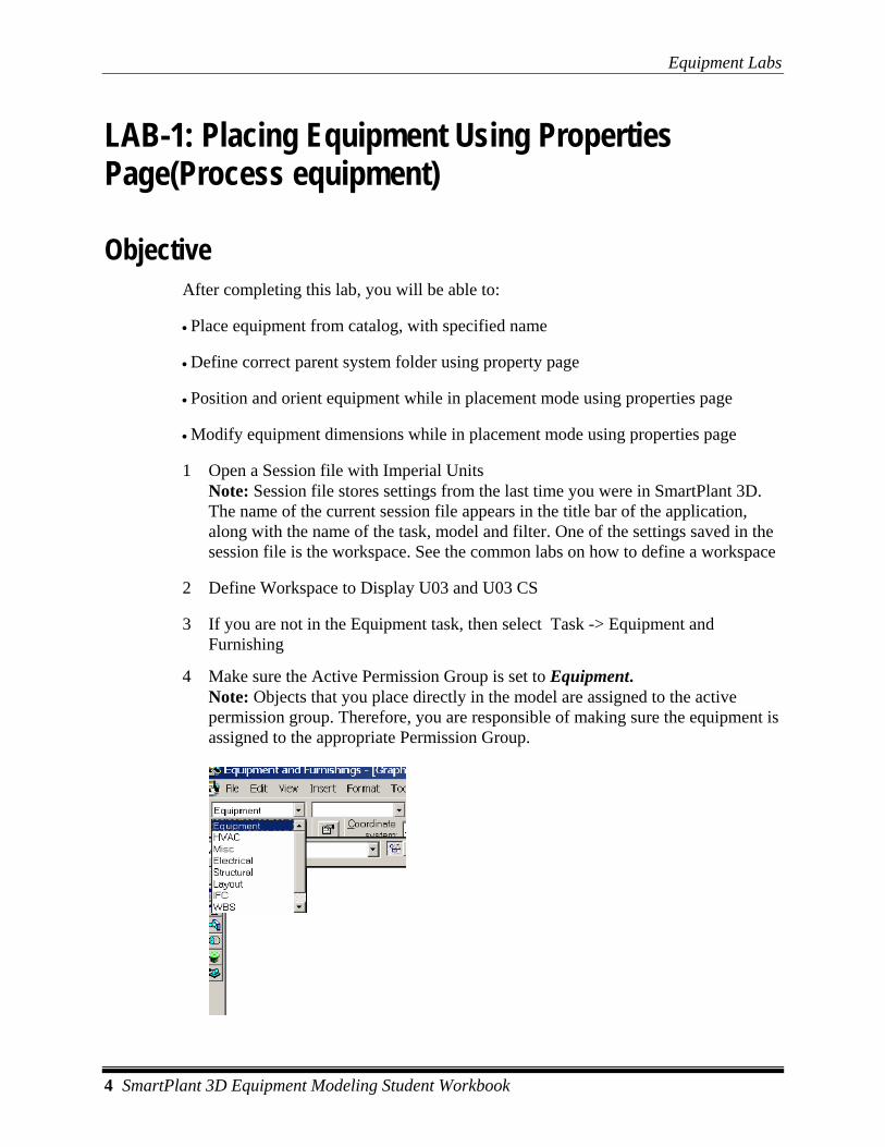
3 If you are not in the Equipment task, then select Task -> Equipment and Furnishing
4 Make sure the Active Permission Group is set to Equipment. Note: Objects that you place directly in the model are assigned to the active permission group. Therefore, you are responsible of making sure the equipment is assigned to the appropriate Permission Group.
Equipment Labs
SmartPlant 3D Equipment Modeling Student Workbook 5
5 Activate PinPoint by Selecting Tools > PinPoint (make sure active Coordinate system is Global)
6 Select Place Equipment Command
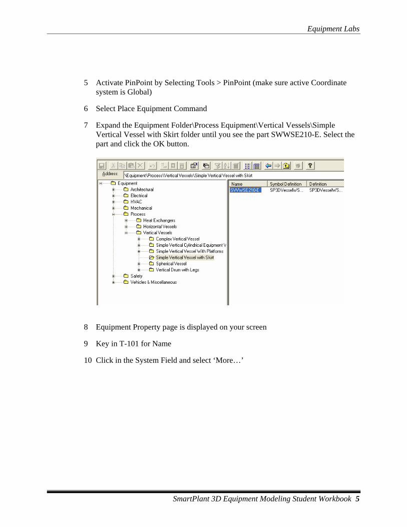
7 Expand the Equipment Folder\Process Equipment\Vertical Vessels\Simple Vertical Vessel with Skirt folder until you see the part SWWSE210-E. Select the part and click the OK button.
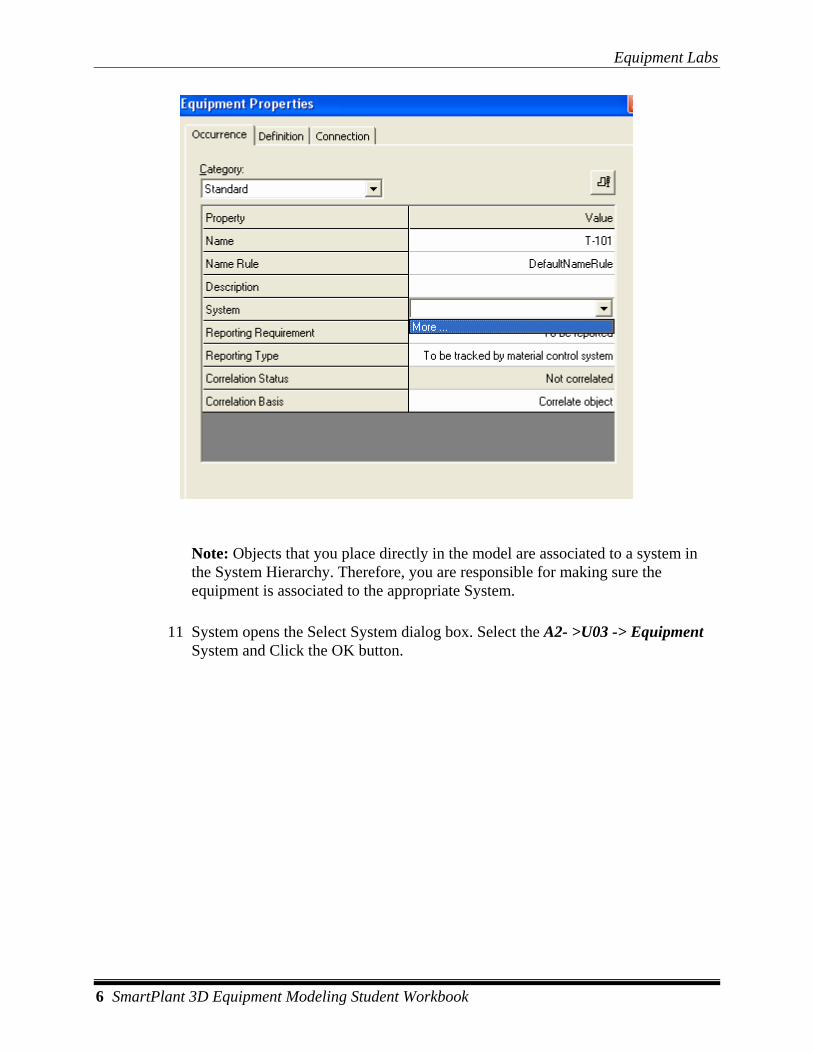
8 Equipment Property page is displayed on your screen
9 Key in T-101 for Name
10 Click in the System Field and select ‘More…’
Equipment Labs
6 SmartPlant 3D Equipment Modeling Student Workbook
Note: Objects that you place directly in the model are associated to a system in the System Hierarchy. Therefore, you are responsible for making sure the equipment is associated to the appropriate System.
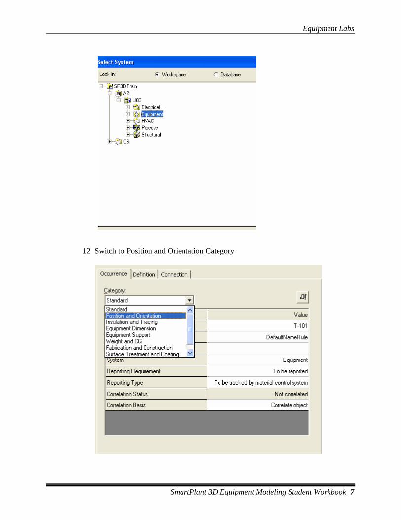
11 System opens the Select System dialog box. Select the A2- >U03 -> Equipment System and Click the OK button.
Equipment Labs
SmartPlant 3D Equipment Modeling Student Workbook 7
12 Switch to Position and Orientation Category
Equipment Labs
8 SmartPlant 3D Equipment Modeling Student Workbook
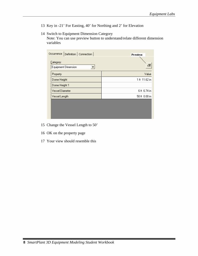
13 Key in -21’ For Easting, 40’ for Northing and 2’ for Elevation
14 Switch to Equipment Dimension Category Note: You can use preview button to understand/relate different dimension variables
15 Change the Vessel Length to 50’
16 OK on the property page
17 Your view should resemble this

Equipment Labs
SmartPlant 3D Equipment Modeling Student Workbook 9

Equipment Labs
10 SmartPlant 3D Equipment Modeling Student Workbook
LAB-2: Placing Equipment Using Properties Page(Mechanical equipment)
Objective After completing this lab, you will be able to:
• Place equipment from catalog, with specified name
• Define correct parent system folder using property page
• Position and orient equipment while in placement mode using properties page
• Modify equipment dimensions while in placement mode using properties page
1 Open a Session file with Imperial Units
2 Define Workspace to Display U03 and U03 CS
3 If you are not in the Equipment task, then select Task -> Equipment and Furnishing
4 Make sure the Active Permission Group is set to Equipment.
5 Expand the Equipment\Equipment\Mechanical Equipment\Pumps\Pump until you see the part CPump002A8x6-E. Select the part and click the OK button.
6 Equipment Property page is displayed on your screen

Equipment Labs
SmartPlant 3D Equipment Modeling Student Workbook 11
7 Key in P-101 for Name
8 Click in the System Field and select ‘More…’
9 System opens the Select System dialog box. Select the A2- >U0 3-> Equipment System and Click the OK button.
10 Switch to Position and Orientation Category
11 Key in 1’ For Easting, 12’ for Northing and 2’ for Elevation
12 OK on the property page
13 Your View should resemble this (Only Grids and Equipment Shown)
Equipment Labs
12 SmartPlant 3D Equipment Modeling Student Workbook
LAB-3: Rotating Equipment While Placing / After Placement
Objective After completing this lab, you will be able to:
• Place equipment using property page
• Rotate equipment during/after placement using arrow keys
1 Open a Session file with Imperial Units
1 Define Workspace to Display U04 and U04 CS
2 Activate PinPoint if not already active
3 Make Sure Active Coordinate System is set to Global
4 Select Place Equipment command from the vertical toolbar to open the Select Equipment Dialog box.
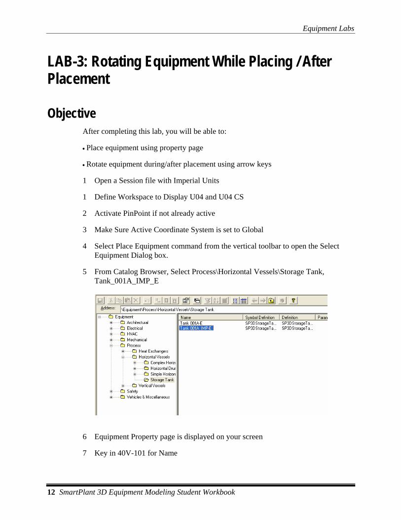
5 From Catalog Browser, Select Process\Horizontal Vessels\Storage Tank, Tank_001A_IMP_E
6 Equipment Property page is displayed on your screen
7 Key in 40V-101 for Name
Equipment Labs
SmartPlant 3D Equipment Modeling Student Workbook 13
8 Click in the System Field and select ‘More…’
9 System opens the Select System dialog box. Select the A2- > U04 -> Equipment System and Click the OK button.
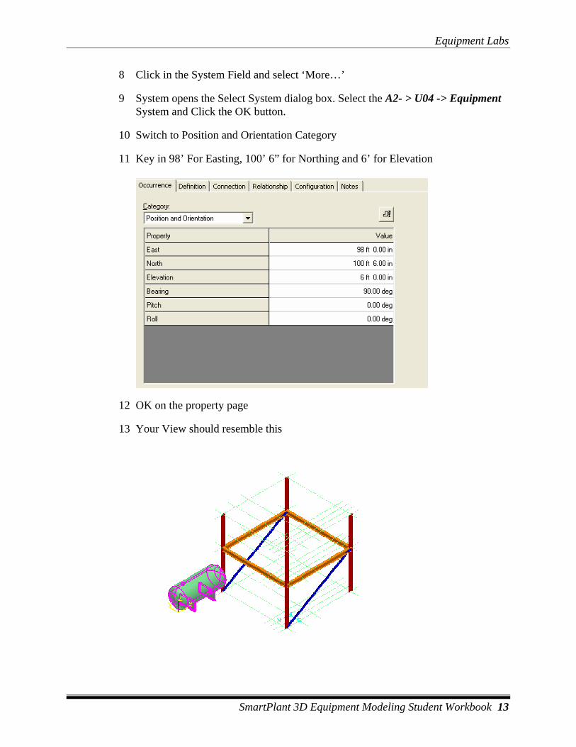
10 Switch to Position and Orientation Category
11 Key in 98’ For Easting, 100’ 6” for Northing and 6’ for Elevation
12 OK on the property page
13 Your View should resemble this
Equipment Labs
14 SmartPlant 3D Equipment Modeling Student Workbook
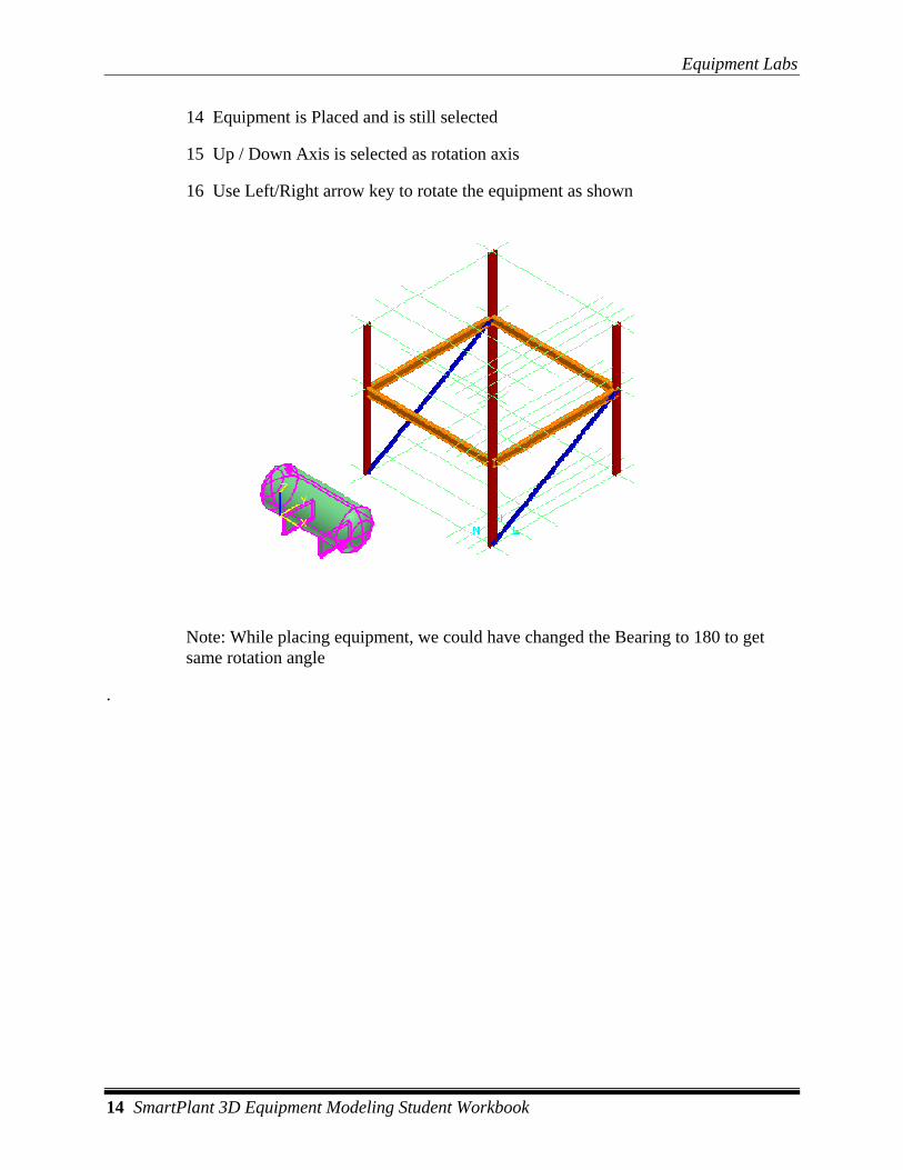
14 Equipment is Placed and is still selected
15 Up / Down Axis is selected as rotation axis
16 Use Left/Right arrow key to rotate the equipment as shown
Note: While placing equipment, we could have changed the Bearing to 180 to get same rotation angle
.
Equipment Labs
SmartPlant 3D Equipment Modeling Student Workbook 15
LAB-4: Placing Designed Equipment and Equipment Component
Objective After completing this lab, you will be able to:
• Place designed equipment using property page
• Pace equipment component
• Change active Coordinate system
1 Open a Session file with Imperial Units
2 Define Workspace to Display U04 and U04 CS
3 Activate PinPoint if not already active
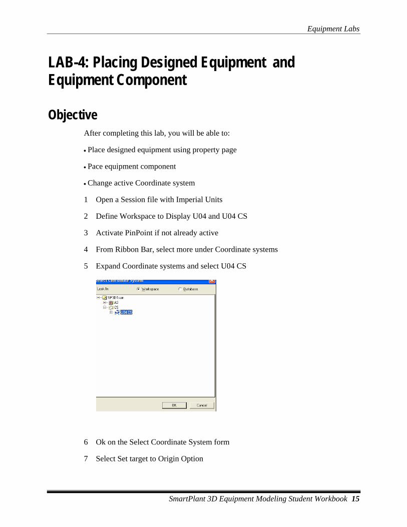
4 From Ribbon Bar, select more under Coordinate systems
5 Expand Coordinate systems and select U04 CS
6 Ok on the Select Coordinate System form
7 Select Set target to Origin Option

Equipment Labs
16 SmartPlant 3D Equipment Modeling Student Workbook
8 Select Place Designed Equipment Command
9 From Catalog Browser select, \Equipment\Process\Horizontal Vessels\Horizontal Drum with Saddle
10 Equipment Property page is displayed on your screen
11 Key in 41V-101 for Name
12 Click in the System Field and select ‘More…’
13 System opens the Select System dialog box. Select the A2- > U04 -> Equipment System
14 Switch to Position and Orientation Category
15 Key in 5 For Easting, 8 for Northing and 23’ for Elevation
16 OK on the property page
17 Select Place Equipment component command from the vertical toolbar
18 If prompted select 41V-101 from WSE
19 Locate E245 Horizontal Cylindrical Tank using the tree view. Select the part and click the OK button (Equipment Components\Process Components\Vessel &

Equipment Labs
SmartPlant 3D Equipment Modeling Student Workbook 17
Equipment Bodies\Horizontal Vessels and Tanks\Simple Horizontal Cylindrical Equipment Component (E245)
20 Equipment Property page is displayed on your screen
21 Key in Tank for Name
22 Switch to Position and Orientation Category
23 Key in 5 For Easting, 8 for Northing and 23’ for Elevation
24 Switch to Equipment Dimension Category
25 Make the following Changes Vessel Center Height : 5’ 6” Vessel Diameter: 8’ Vessel Length: 14’ 10”
26 Change the Category to Equipment Support
27 Make the following Changes First Support Location: 3’ Second Support Location: 9’ Support Thickness: 6” (6 inches) Support Length: 7’
28 Ok on the form
29 Your View should resemble this (only grids and equipment shown)
Equipment Labs
18 SmartPlant 3D Equipment Modeling Student Workbook
LAB-5: Placing Equipment with Mate Relationship
Objective After completing this lab, you will be able to:
• Create a Mate relationship between equipment and elevation plane
1 Open a Session file with Imperial Units
2 Define Workspace to Display U04 and U04 CS
1 Activate PinPoint if not already active
2 Make Sure Active Coordinate System is Set to U04 CS
3 Select Place Equipment command from the vertical toolbar to open the select Equipment Dialog box
4 Select Pump_001A_IMP-E, under Equipment\Mechanical\Pumps\Pump
5 Ok on the property page(without making any changes)
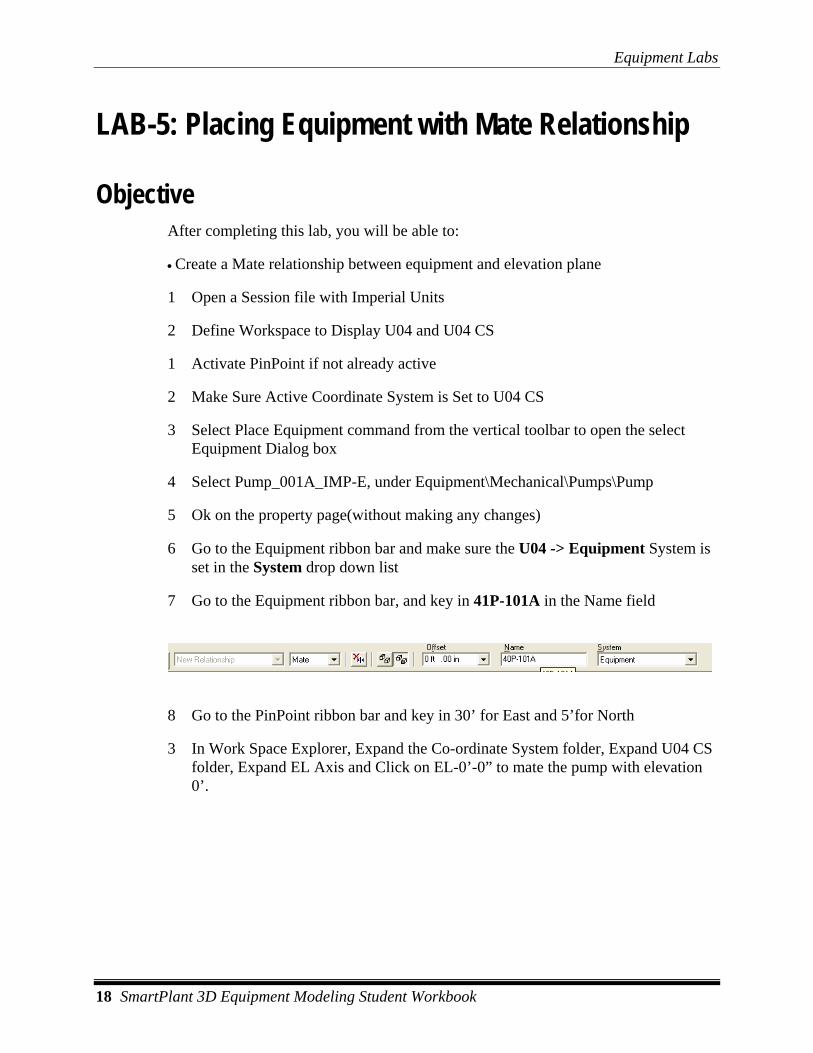
6 Go to the Equipment ribbon bar and make sure the U04 -> Equipment System is set in the System drop down list
7 Go to the Equipment ribbon bar, and key in 41P-101A in the Name field
8 Go to the PinPoint ribbon bar and key in 30’ for East and 5’for North
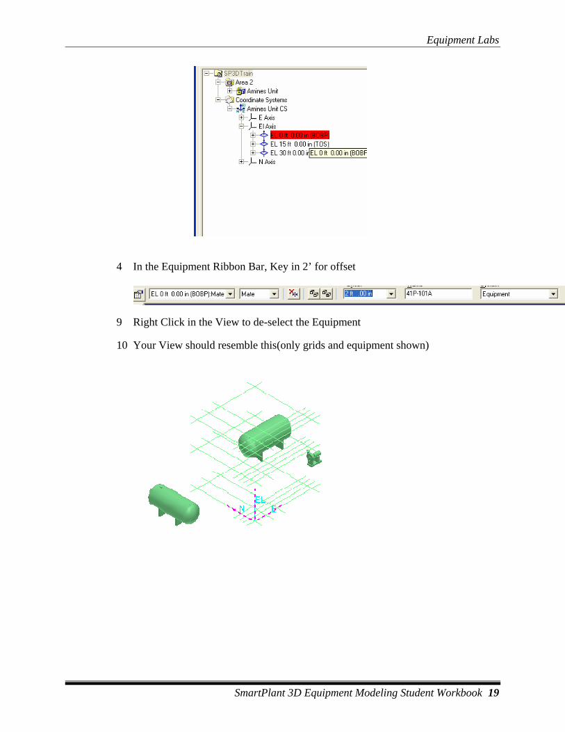
3 In Work Space Explorer, Expand the Co-ordinate System folder, Expand U04 CS folder, Expand EL Axis and Click on EL-0’-0” to mate the pump with elevation 0’.
Equipment Labs
SmartPlant 3D Equipment Modeling Student Workbook 19
4 In the Equipment Ribbon Bar, Key in 2’ for offset
9 Right Click in the View to de-select the Equipment
10 Your View should resemble this(only grids and equipment shown)
Equipment Labs
20 SmartPlant 3D Equipment Modeling Student Workbook
LAB-6: Equipment Modification
Objective After completing this lab, you will be able to:
• Make changes to equipment/nozzle properties
1 Open a Session file with Imperial Units
2 Define Workspace to Display U04 and U04 CS
3 In workspace explorer expand 40V-101
4 Select Nozzle STNoz1 under, Equipment 40V-101
5 Open property page for nozzle STNoz1
6 Change the size to 6” and name to “A”
7 Ok on the form
8 Select Suction Nozzle under 41P-101A
9 Open its Properties page
10 Change the size to 8” and name to N1 Note: After making changes, select Apply instead of OK. You do not need to close the properties page, just click on the next object to open new page. Now you have made changes to suction nozzle, hit apply and select discharge nozzle
11 Change the discharge to 6” and name to N2
12 Select Nozzle “C”, under T-101 (in U03)
13 Change N1 to 59’(location tab)
Equipment Labs
SmartPlant 3D Equipment Modeling Student Workbook 21
LAB-7: Moving / Copying Equipment
Objective After completing this lab, you will be able to:
• Move equipment using from/to point
• Copy and paste equipment
1 Open a Session file with Imperial Units
2 Define Workspace to Display U04 and U04 CS
3 Set Coordinate system to Global
4 Select Set target to origin option
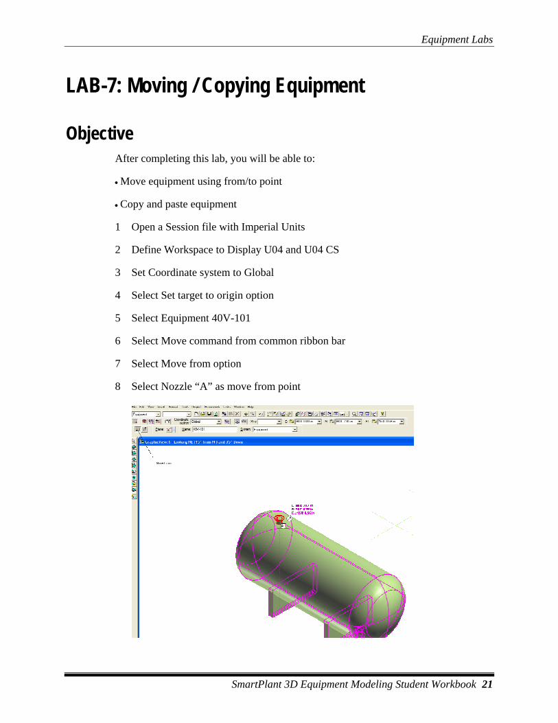
5 Select Equipment 40V-101
6 Select Move command from common ribbon bar
7 Select Move from option
8 Select Nozzle “A” as move from point
Equipment Labs
22 SmartPlant 3D Equipment Modeling Student Workbook
9 Key in 98’ for East, 99’ 8” for North and 8’ 3” for elevation
10 Click in the view to place the equipment at new location
11 Set Active Coordinate system to U04 CS
12 Select Set target to origin option
13 Select pump 41P-101A
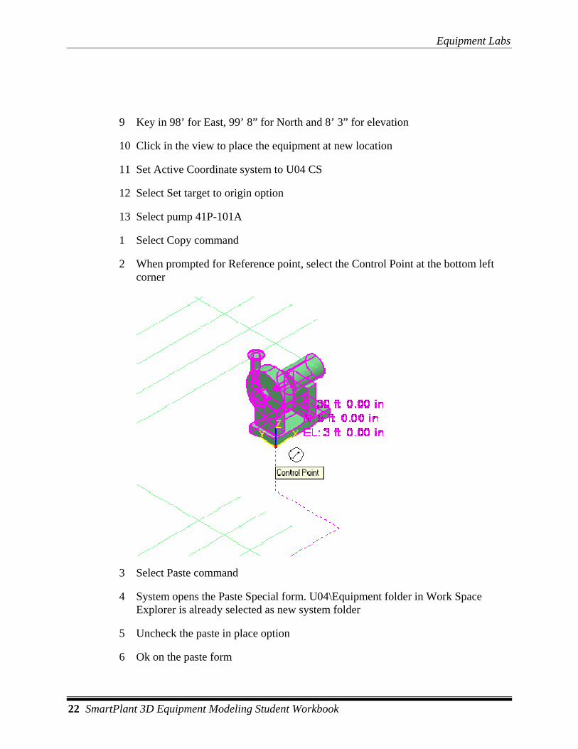
1 Select Copy command
2 When prompted for Reference point, select the Control Point at the bottom left corner
3 Select Paste command
4 System opens the Paste Special form. U04\Equipment folder in Work Space Explorer is already selected as new system folder
5 Uncheck the paste in place option
6 Ok on the paste form
Equipment Labs
SmartPlant 3D Equipment Modeling Student Workbook 23
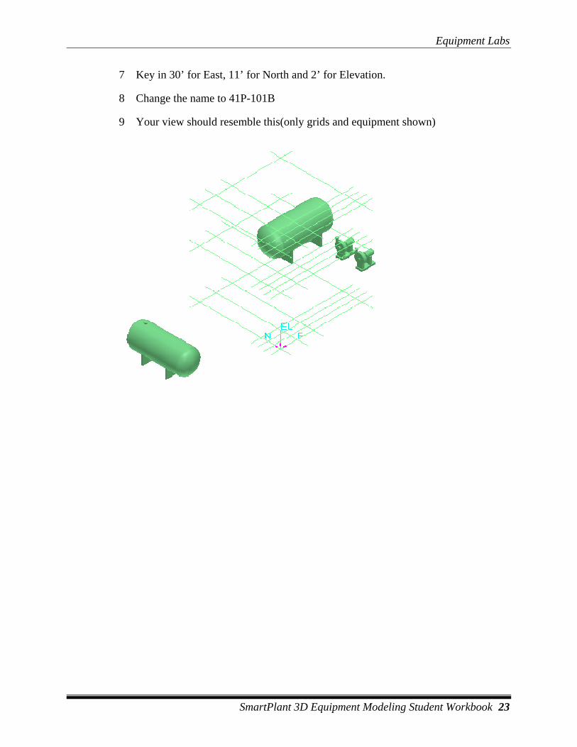
7 Key in 30’ for East, 11’ for North and 2’ for Elevation.
8 Change the name to 41P-101B
9 Your view should resemble this(only grids and equipment shown)
Equipment Labs
24 SmartPlant 3D Equipment Modeling Student Workbook
LAB-8: Placing shapes to Build Designed Equipment
Objective After completing this lab, you will be able to:
• Build designed equipment by putting shapes together
• Use connect relationship to position/locate shapes
1 Open a Session file with Imperial Units
2 Define Workspace to Display U01 and U01 CS
3 Change the Active Coordinate system to U01
4 Select set target to origin option
5 Select Place Designed Equipment Command
6 From Catalog Browser select \Equipment\Process\Heat Exchangers\Kettle Heat Exchanger
1 Equipment Property page is displayed on your screen
2 Key in E-102 for Name
3 Click in the System Field and select ‘More…’
4 System opens the Select System dialog box. Select the A2- > U01 -> Equipment System and Click the OK button.
5 Switch to Position and Orientation Category
6 Key in 5 For Easting, -20 for Northing and 6’ for Elevation
7 Switch to Definition Tab and set the classifications as shown (Definition Tab, Standard Category)

Equipment Labs
SmartPlant 3D Equipment Modeling Student Workbook 25
8 Select Place shape Command(click on place shape command and hold the left mouse button to display list of shapes). Select Cylinder Shape from the shape options.
9 If prompted, select Designed equipment E-102 in WSE
10 Enter A=20’ and B=6’
11 Using PinPoint place the shape at
Easting: 5 ft relative to the U01 coordinate system
Northing: -20 ft relative to the U01 coordinate system
Elevation: 6 ft relative to the U01 coordinate system
Equipment Labs
26 SmartPlant 3D Equipment Modeling Student Workbook
12 Select Place shape command and select Eccentric Cone from shapes
13 Select Designed equipment E-102
14 Enter A=3 ft, B=6 ft, C= 4 ft and Click OK
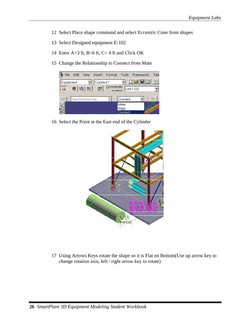
15 Change the Relationship to Connect from Mate
16 Select the Point at the East end of the Cylinder
17 Using Arrows Keys rotate the shape so it is Flat on Bottom(Use up arrow key to change rotation axis, left / right arrow key to rotate)
Equipment Labs
SmartPlant 3D Equipment Modeling Student Workbook 27
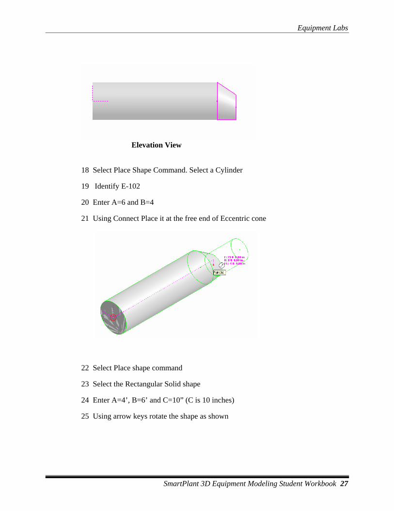
Elevation View
18 Select Place Shape Command. Select a Cylinder
19 Identify E-102
20 Enter A=6 and B=4
21 Using Connect Place it at the free end of Eccentric cone
22 Select Place shape command
23 Select the Rectangular Solid shape
24 Enter A=4’, B=6’ and C=10” (C is 10 inches)
25 Using arrow keys rotate the shape as shown
Equipment Labs
28 SmartPlant 3D Equipment Modeling Student Workbook
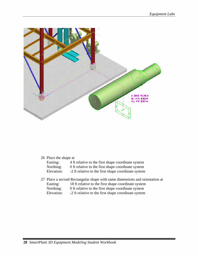
26 Place the shape at Easting: 4 ft relative to the first shape coordinate system Northing: 0 ft relative to the first shape coordinate system Elevation: -2 ft relative to the first shape coordinate system
27 Place a second Rectangular shape with same dimensions and orientation at Easting: 18 ft relative to the first shape coordinate system Northing: 0 ft relative to the first shape coordinate system Elevation: -2 ft relative to the first shape coordinate system
Equipment Labs
SmartPlant 3D Equipment Modeling Student Workbook 29
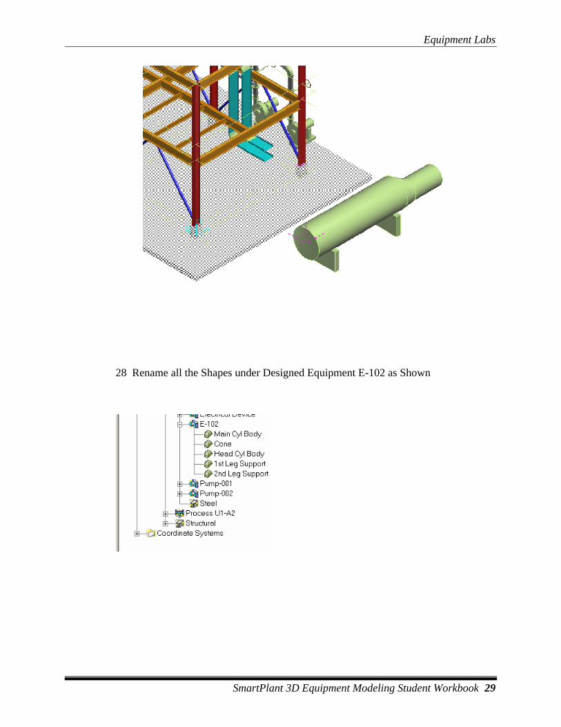
28 Rename all the Shapes under Designed Equipment E-102 as Shown
Equipment Labs
30 SmartPlant 3D Equipment Modeling Student Workbook
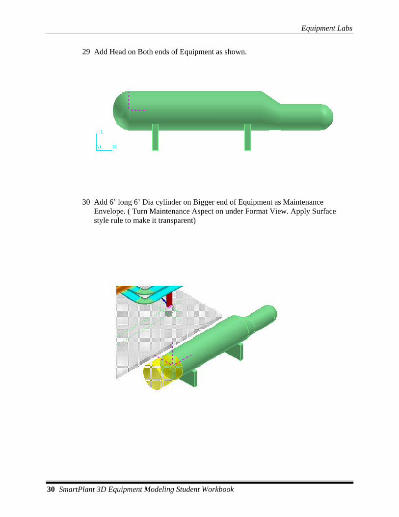
29 Add Head on Both ends of Equipment as shown.
30 Add 6’ long 6’ Dia cylinder on Bigger end of Equipment as Maintenance Envelope. ( Turn Maintenance Aspect on under Format View. Apply Surface style rule to make it transparent)
Equipment Labs
SmartPlant 3D Equipment Modeling Student Workbook 31
LAB-9: Placing Nozzles
Objective After completing this lab, you will be able to:
• Add nozzles using different options
1 Open a Session file with Imperial Units
2 Define Workspace to Display U01 and U01 CS
3 Change the Active Coordinate system to U01
4 Select set target to origin option
5 Select Place Nozzle Command
6 Select Shape(Main Cyl Body) under E-102
7 From the Port Type control on the Nozzle Properties form select Piping Straight Nozzle.
8 Define the following Properties:
PortIndex: 1 NorminalSize: 8 NPDUnitType: in Termination Class: Bolted Termination SubClass: Flanged End Preparation: RFFE End Practice: US Practice End Standard: Default Rating Practice: US Practice Pressure Rating: CL150 Flow Direction: Flow leaves this port
Scroll down
Nozzle Length: 1 ft Name: N1
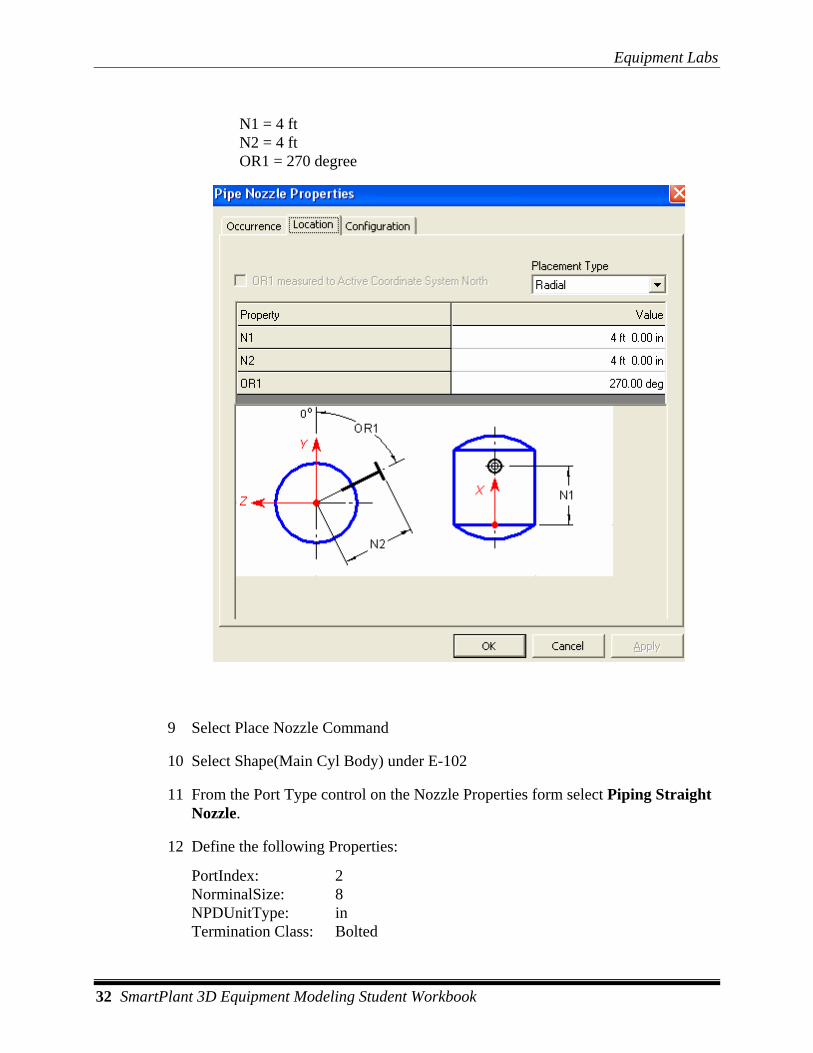
Switch to the location tab and select Radial in the Placement Type control. Define the following:
Equipment Labs
32 SmartPlant 3D Equipment Modeling Student Workbook
N1 = 4 ft N2 = 4 ft OR1 = 270 degree
9 Select Place Nozzle Command
10 Select Shape(Main Cyl Body) under E-102
11 From the Port Type control on the Nozzle Properties form select Piping Straight Nozzle.
12 Define the following Properties:
PortIndex: 2 NorminalSize: 8 NPDUnitType: in Termination Class: Bolted
Equipment Labs
SmartPlant 3D Equipment Modeling Student Workbook 33
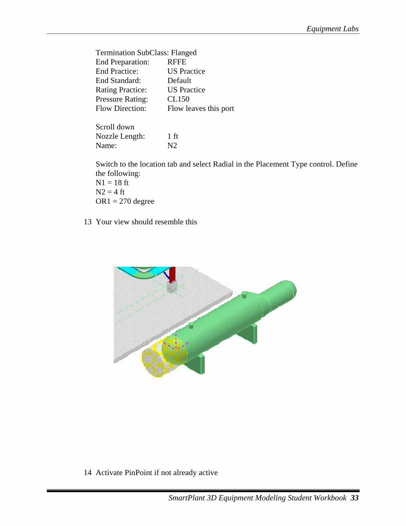
Termination SubClass: Flanged End Preparation: RFFE End Practice: US Practice End Standard: Default Rating Practice: US Practice Pressure Rating: CL150 Flow Direction: Flow leaves this port
Scroll down Nozzle Length: 1 ft Name: N2 Switch to the location tab and select Radial in the Placement Type control. Define the following: N1 = 18 ft N2 = 4 ft OR1 = 270 degree
13 Your view should resemble this
14 Activate PinPoint if not already active
Equipment Labs
34 SmartPlant 3D Equipment Modeling Student Workbook
15 Define Workspace to Display U04 and U04 CS
16 Change the Active coordinate system to 41V-101(U04\equipment\)
17 Select Set target to origin option
18 Select Place Nozzle Command
19 Select Shape(Tank) under 41V-101
20 From the Port Type control on the Nozzle Properties form select Piping Straight Nozzle.
21 Define the following Properties, 8”, RFFE, Length 1’, Name N1 (Define Rest of the properties as previous labs)
22 From Location Tab, select Position by point option. Ok on the form
23 Key in East 1, North 0 and Elevation 5’
24 Rotate the Nozzle using arrow keys. Make sure RFFE is on top
25 Click to place the nozzle
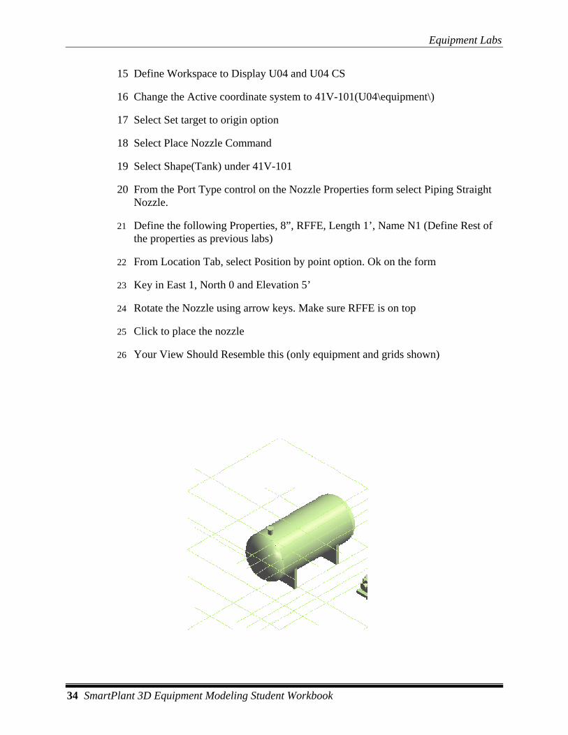
26 Your View Should Resemble this (only equipment and grids shown)
Equipment Labs
SmartPlant 3D Equipment Modeling Student Workbook 35
27 Select Place nozzle command
28 Select same Tank again
29 Define the following Properties, 8”, RFFE, Length 1’, Name N2 (Define Rest of the properties as previous labs)
30 From Location Tab, select Position by point option. Ok on the form
31 Key in East 13 6”, North 0 and Elevation -4’ 10”
32 Rotate the Nozzle using arrow keys. Make sure RFFE is at the bottom
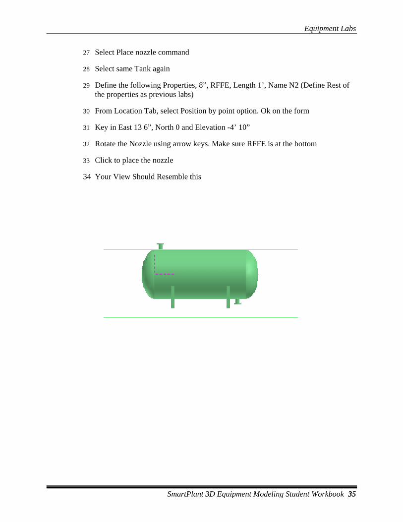
33 Click to place the nozzle
34 Your View Should Resemble this
Equipment Labs
36 SmartPlant 3D Equipment Modeling Student Workbook
LAB-9: Importing Equipment from External Modeler
Objective After completing this lab, you will be able to:
• Place equipment by importing from Sat/dgn file
1 Open a Session file with Imperial Units
2 Define Workspace to Display U02 and U02 CS
3 Activate PinPoint if not already active
4 Change the active coordinate system to U02 CS
5 Select Set target to origin option
6 Select Place Designed Equipment Command
7 From Catalog select \Equipment\Process\Horizontal Vessels\Horizontal Drum with Saddle
8 OK on the property page
9 Key in East 15’, North 30’ and Elevation 0
10 Left click to place the equipment
11 Change the System to U02, Equipment
12 Change the name to DR-100
13 Select the place imported shape from file command on the vertical toolbar.
14 If prompted, select DR-100 from the workspace explorer
15 Select the Tank_Shape.sat file from specified location
16 In the Display aspects dialog, select Simple Physical and click OK.
17 Key in East 15’, North 30’ and Elevation 0
18 Change the name of tank to Drum Body
Equipment Labs
SmartPlant 3D Equipment Modeling Student Workbook 37
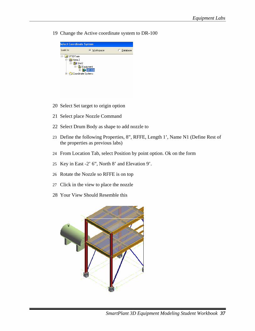
19 Change the Active coordinate system to DR-100
20 Select Set target to origin option
21 Select place Nozzle Command
22 Select Drum Body as shape to add nozzle to
23 Define the following Properties, 8”, RFFE, Length 1’, Name N1 (Define Rest of the properties as previous labs)
24 From Location Tab, select Position by point option. Ok on the form
25 Key in East -2’ 6”, North 8’ and Elevation 9’.
26 Rotate the Nozzle so RFFE is on top
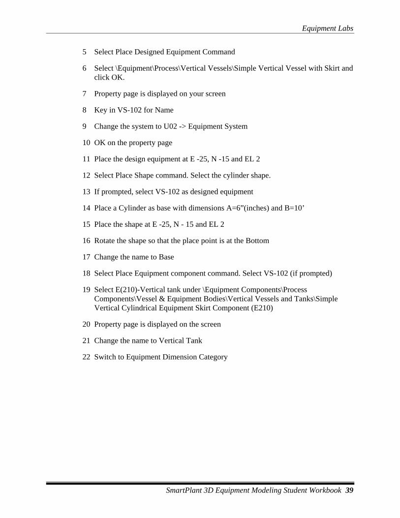
27 Click in the view to place the nozzle
28 Your View Should Resemble this

Equipment Labs
38 SmartPlant 3D Equipment Modeling Student Workbook
LAB-10: Building Equipment from Shapes and Equipment Component(Optional Lab)
Objective After completing this lab, you will be able to:
• Design equipment by putting shapes and equipment component
NOTE: These are not detailed steps. Just an outline of things to consider
1 Open a Session file with Imperial Units
2 Define Workspace to Display U02 and U02 CS
3 Activate PinPoint if not already active
4 Change the active coordinate system to U02 CS
Equipment Labs
SmartPlant 3D Equipment Modeling Student Workbook 39
5 Select Place Designed Equipment Command
6 Select \Equipment\Process\Vertical Vessels\Simple Vertical Vessel with Skirt and click OK.
7 Property page is displayed on your screen
8 Key in VS-102 for Name
9 Change the system to U02 -> Equipment System
10 OK on the property page
11 Place the design equipment at E -25, N -15 and EL 2
12 Select Place Shape command. Select the cylinder shape.
13 If prompted, select VS-102 as designed equipment
14 Place a Cylinder as base with dimensions A=6”(inches) and B=10’
15 Place the shape at E -25, N - 15 and EL 2
16 Rotate the shape so that the place point is at the Bottom
17 Change the name to Base
18 Select Place Equipment component command. Select VS-102 (if prompted)
19 Select E(210)-Vertical tank under \Equipment Components\Process Components\Vessel & Equipment Bodies\Vertical Vessels and Tanks\Simple Vertical Cylindrical Equipment Skirt Component (E210)
20 Property page is displayed on the screen
21 Change the name to Vertical Tank
22 Switch to Equipment Dimension Category
Equipment Labs
40 SmartPlant 3D Equipment Modeling Student Workbook
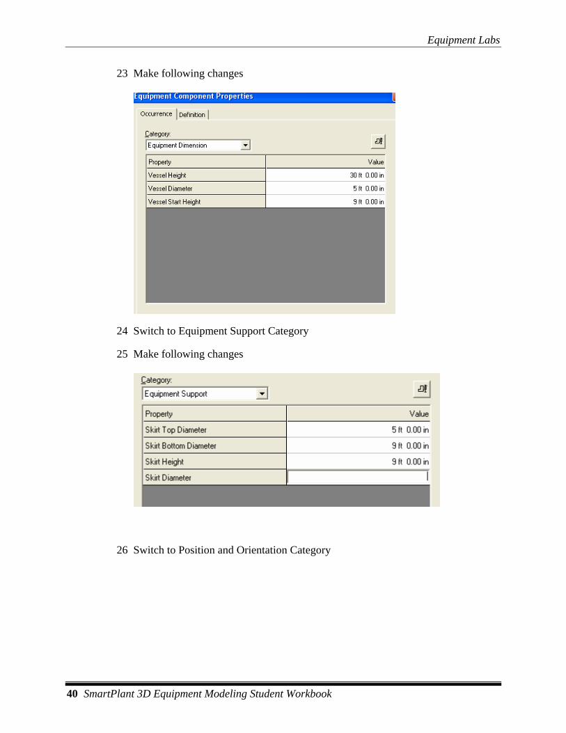
23 Make following changes
24 Switch to Equipment Support Category
25 Make following changes
26 Switch to Position and Orientation Category
Equipment Labs
SmartPlant 3D Equipment Modeling Student Workbook 41
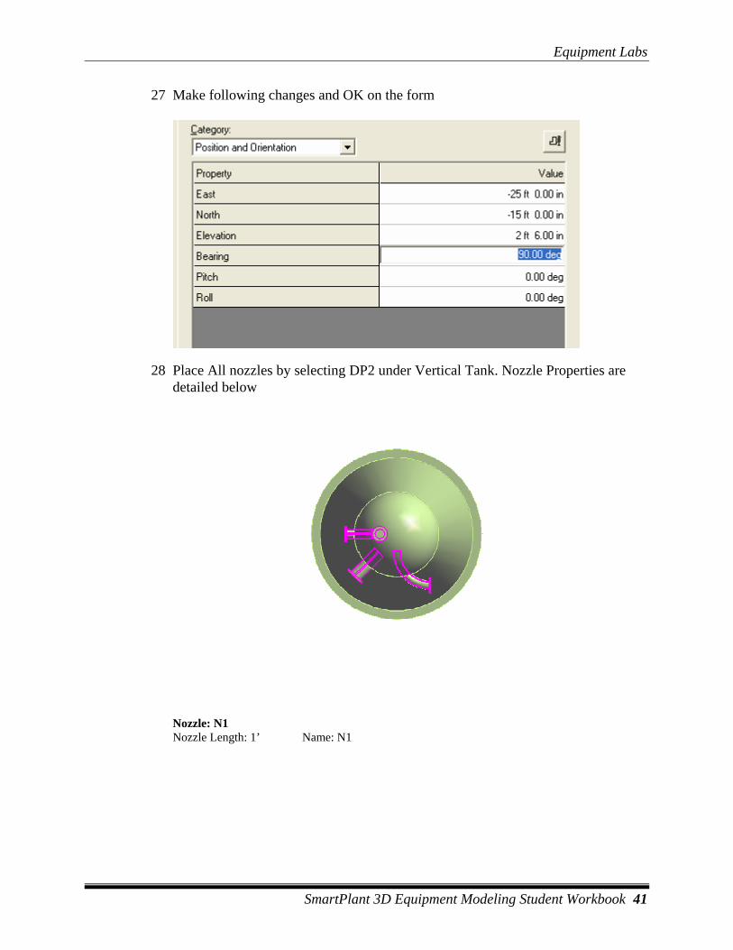
27 Make following changes and OK on the form
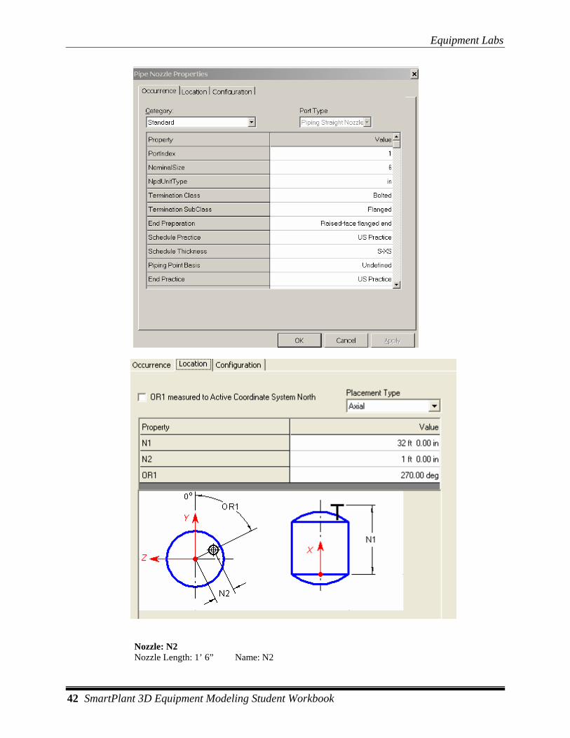
28 Place All nozzles by selecting DP2 under Vertical Tank. Nozzle Properties are detailed below
Nozzle: N1 Nozzle Length: 1’ Name: N1
Equipment Labs
42 SmartPlant 3D Equipment Modeling Student Workbook
Nozzle: N2 Nozzle Length: 1’ 6” Name: N2
Equipment Labs
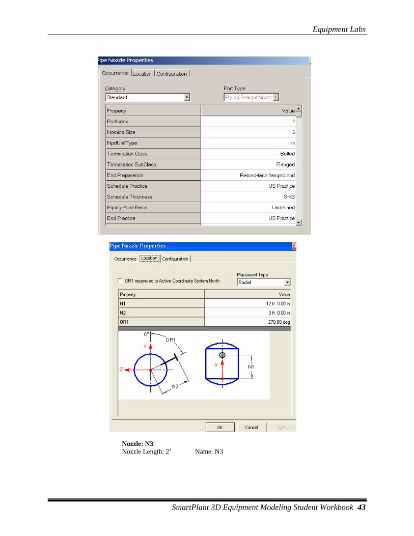
SmartPlant 3D Equipment Modeling Student Workbook 43
Nozzle: N3 Nozzle Length: 2’ Name: N3
Equipment Labs
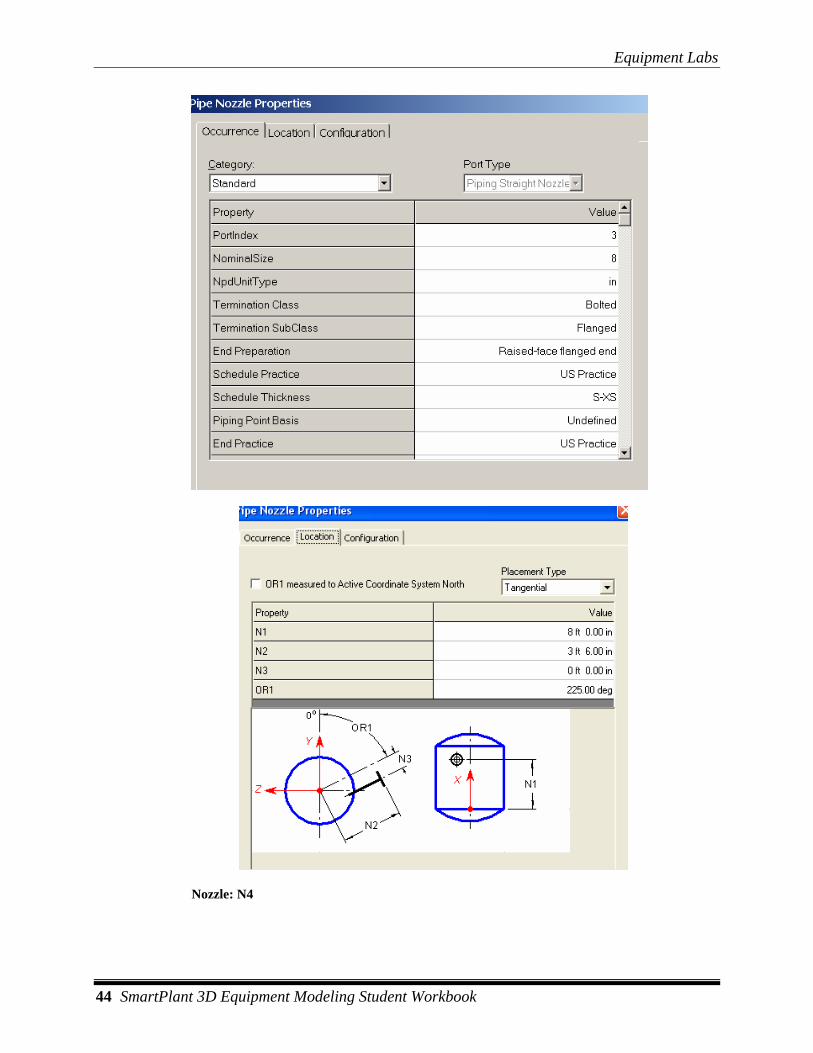
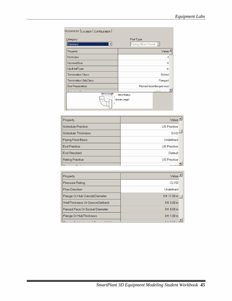
44 SmartPlant 3D Equipment Modeling Student Workbook
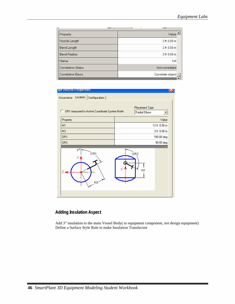
Nozzle: N4
Equipment Labs
SmartPlant 3D Equipment Modeling Student Workbook 45
Equipment Labs
46 SmartPlant 3D Equipment Modeling Student Workbook
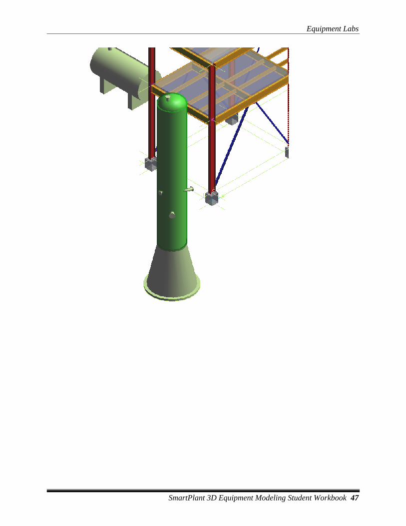
Adding Insulation Aspect
Add 3” insulation to the main Vessel Body( to equipment component, not design equipment) Define a Surface Style Rule to make Insulation Translucent
Equipment Labs
SmartPlant 3D Equipment Modeling Student Workbook 47
Equipment Labs
48 SmartPlant 3D Equipment Modeling Student Workbook
LAB-11: Placing Equipment from PID
Objective After this lab students will be able to place and model Designed Equipment by transferring Data from PID
Lecture: Instructor Needs to show/explain placing equipment and Nozzles from PID
1 Open a session file and define a filter for your workspace that includes the U02 and its coordinate system.
2 Activate PinPoint if not already active
3 Change the coordinate system to U02 CS
4 Select Set target to origin option
5 Go to Smartplant > View P&ID
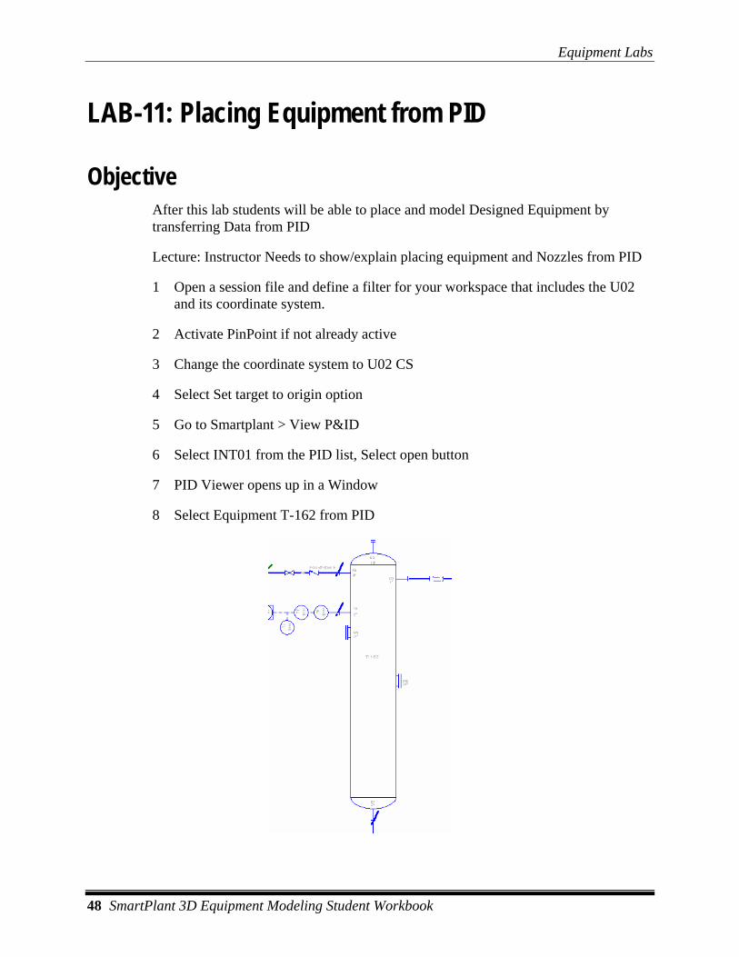
6 Select INT01 from the PID list, Select open button
7 PID Viewer opens up in a Window
8 Select Equipment T-162 from PID
Equipment Labs
SmartPlant 3D Equipment Modeling Student Workbook 49
9 Select Place Equipment Command
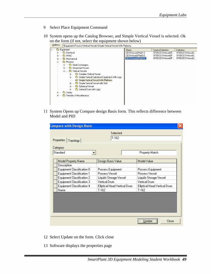
10 System opens up the Catalog Browser, and Simple Vertical Vessel is selected. Ok on the form (if not, select the equipment shown below)
11 System Opens up Compare design Basis form. This reflects difference between Model and PID
12 Select Update on the form. Click close
13 Software displays the properties page
Equipment Labs
50 SmartPlant 3D Equipment Modeling Student Workbook
14 System fills the name from PID (T-162)
15 Change the system to U02 > Equipment
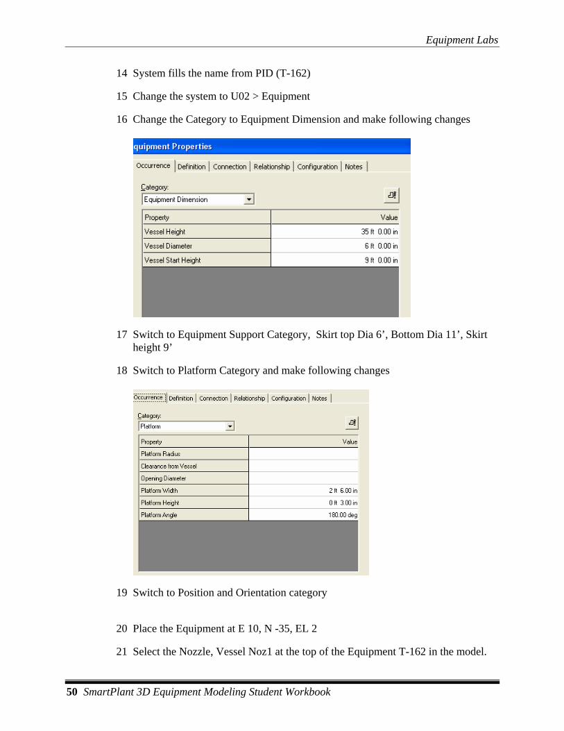
16 Change the Category to Equipment Dimension and make following changes
17 Switch to Equipment Support Category, Skirt top Dia 6’, Bottom Dia 11’, Skirt height 9’
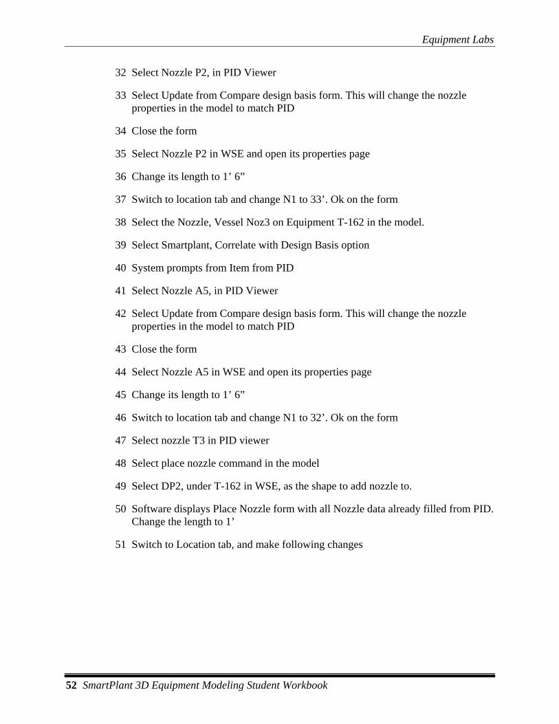
18 Switch to Platform Category and make following changes
19 Switch to Position and Orientation category
20 Place the Equipment at E 10, N -35, EL 2
21 Select the Nozzle, Vessel Noz1 at the top of the Equipment T-162 in the model.

Equipment Labs
SmartPlant 3D Equipment Modeling Student Workbook 51
22 Select Smartplant, Correlate with Design Basis option
23 System prompts from Item from PID
24 Select Nozzle B2, at the top in PID Viewer
25 Select Update from Compare design basis form. This will change the nozzle properties in the model to match PID
26 Close the form
27 Select Nozzle B2 in WSE and open its properties page
28 Change its length to 1’ 6”
29 Select the Nozzle, Vessel Noz2 on Equipment T-162 in the model.
30 Select Smartplant, Correlate with Design Basis option
31 System prompts from Item from PID
Equipment Labs
52 SmartPlant 3D Equipment Modeling Student Workbook
32 Select Nozzle P2, in PID Viewer
33 Select Update from Compare design basis form. This will change the nozzle properties in the model to match PID
34 Close the form
35 Select Nozzle P2 in WSE and open its properties page
36 Change its length to 1’ 6”
37 Switch to location tab and change N1 to 33’. Ok on the form
38 Select the Nozzle, Vessel Noz3 on Equipment T-162 in the model.
39 Select Smartplant, Correlate with Design Basis option
40 System prompts from Item from PID
41 Select Nozzle A5, in PID Viewer
42 Select Update from Compare design basis form. This will change the nozzle properties in the model to match PID
43 Close the form
44 Select Nozzle A5 in WSE and open its properties page
45 Change its length to 1’ 6”
46 Switch to location tab and change N1 to 32’. Ok on the form
47 Select nozzle T3 in PID viewer
48 Select place nozzle command in the model
49 Select DP2, under T-162 in WSE, as the shape to add nozzle to.
50 Software displays Place Nozzle form with all Nozzle data already filled from PID. Change the length to 1’
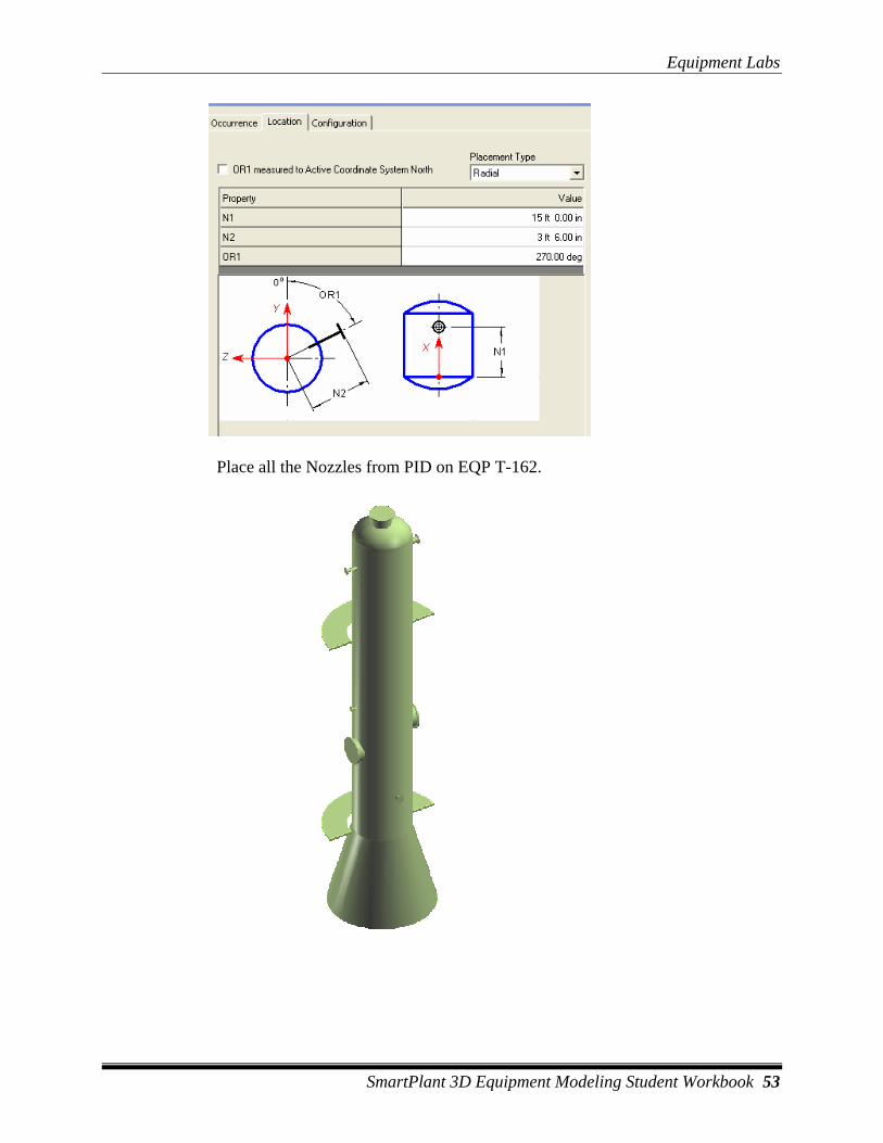
51 Switch to Location tab, and make following changes
Equipment Labs
SmartPlant 3D Equipment Modeling Student Workbook 53
Place all the Nozzles from PID on EQP T-162.
Equipment Labs
54 SmartPlant 3D Equipment Modeling Student Workbook
52 Change your Workspace to Display all Filter
53 Expand U04, Equipment and select 41P-101A.
54 Select Copy command.
55 Select Top of Discharge nozzle as Reference point.
56 Select Paste command. Check Paste in Place option and Ok on the form
57 Select New Equipment (copied equipment) if not already selected
58 Open properties page
59 Change system to U02, equipment.
60 Switch to position and orientation category
61 Change the coordinates to E 25, N -50 and EL 3 WRT U02 CS
62 Select the copied equipment and go to Smartplant, Correlate with Design Basis.
63 System prompts for Select PID item to be correlated
64 In PID viewer select pump P-162. System displays Compare with Design Basis form. Select Update.
65 Select nozzle N1 under pump, select Smartplant compare design basis.
66 Update on the form. Close the form. This should turn nozzle green.
67 Update nozzle N2 same way. When done. The equipment and nozzles should turn green in the PID. If Equipment is not green, Select the equipment and select Compare with Design Basis. Select update. This will turn Equipment and Nozzles green in PID.

Equipment Labs
SmartPlant 3D Equipment Modeling Student Workbook 55


