Page 1 of 69 SP624 SP624 S T A T E O F T E N N E S S E E Rev. 03-17-15 January 1, 2015 Rev. 08-27-15 Rev. 12-7-15 Rev. 5-16-16 SPECIAL PROVISION REGARDING RETAINING WALLS General Description This Special Provision covers the design requirements, submittal of wall design drawings and supporting calculations, materials, construction, measurement, and payment for earth retaining walls. The scope of work for retaining wall construction includes, but is not limited to, the following as required: 1. All grading necessary for wall construction, 2. Undercutting and backfilling of weak surficial zones, and or ground improvement as required by plans 3. Temporary Shoring/Wall 4. Compaction of wall foundations 5. General and local dewatering as required for proper execution of the work 6. Construction of leveling pads 7. Formwork, placement of reinforcing steel, placement and curing of concrete 8. Texture coating or architectural treatment 9. Placement of drainage materials 10. Installation of piling 11. Placement of soil reinforcing devices 12. Placement and compaction of backfill 13. Preparation and erection of wall units 14. Construction of any required caps, copings, or end sections All items included in the construction of the retaining wall shall conform to this Special Provision, the Tennessee Department of Transportation Standard Specifications for Road and Bridge Construction, henceforth referred to as the Standard Specifications, American Society for Testing Materials Standards (ASTM), Federal Highway Administration (FHWA) Technical Publications, t h e c u r r e n t e d i t i o n o f t h e A A S H T O L R F D B r i d g e C o n s t r u c t i o n S p e c i f i c a t i o n s , and the current AASHTO LRFD Bridge Design Specifications with interims, henceforth referred to as the AASHTO LRFD. The architectural treatment and/or texture finish of the walls shall be in accordance with the contract plans.
Transcript
Page 1 of 69
SP624 SP624
S T A T E O F T E N N E S S E E Rev. 03-17-15 January 1, 2015 Rev. 08-27-15 Rev. 12-7-15 Rev. 5-16-16
SPECIAL PROVISION
REGARDING
RETAINING WALLS
General Description This Special Provision covers the design requirements, submittal of wall design drawings and supporting calculations, materials, construction, measurement, and payment for earth retaining walls. The scope of work for retaining wall construction includes, but is not limited to, the following as required:
1. All grading necessary for wall construction, 2. Undercutting and backfilling of weak surficial zones, and or
ground improvement as required by plans 3. Temporary Shoring/Wall 4. Compaction of wall foundations 5. General and local dewatering as required for proper execution of the work 6. Construction of leveling pads 7. Formwork, placement of reinforcing steel, placement and curing of concrete 8. Texture coating or architectural treatment 9. Placement of drainage materials 10. Installation of piling 11. Placement of soil reinforcing devices 12. Placement and compaction of backfill 13. Preparation and erection of wall units 14. Construction of any required caps, copings, or end sections
All items included in the construction of the retaining wall shall conform to this Special Provision, the Tennessee Department of Transportation Standard Specifications for Road and Bridge Construction, henceforth referred to as the Standard Specifications, American Society for Testing Materials Standards (ASTM), Federal Highway Administration (FHWA) Technical Publications, t h e c u r r e n t e d i t i o n o f t h e A A S H T O L R F D B r i d g e C o n s t r u c t i o n S p e c i f i c a t i o n s , and the current AASHTO LRFD Bridge Design Specifications with interims, henceforth referred to as the AASHTO LRFD. The architectural treatment and/or texture finish of the walls shall be in accordance with the contract plans.
Page 2 of 69
SP624 SP624
Design Criteria
The design of all types of earth retaining walls shall be in accordance with this Special Provision and the following Specifications as required:
1. AASHTO LRFD Bridge Design Specifications with interims
3. (FHWA Report No. FHWA-SA-99-018, 1999)Geotechnical Engineering Circular No. 4, Ground Anchors and Anchored Systems
The soil and/or rock properties and specific design values required for wall design are provided in the contract plans.
Submittal Requirements for Contractor/Supplier Prepared Design Plans
The Contractor shall utilize the information contained on the Retaining Wall Conceptual drawing as well as information shown elsewhere in the plans (i.e. utility sheets or traffic control/phasing sheets) to prepare his bid for the wall during the project bidding process and to prepare wall design plans during the construction of the project. The final design shall be submitted subsequent to contract award and a minimum of sixty (60) days prior to start of wall construction and shall include detailed design computations and all details, dimensions, quantities and cross sections necessary to construct the wall. Acceptable wall types will be identified on the concept drawing. Specific wall systems for the Acceptable Wall Types shall be selected from the Department’s Qualified Products List (QPL 38) in effect at time of bid letting. In certain circumstances for a particular project, TDOT may elect to provide a complete, detailed wall design in the contract plans. The Contractor shall not bid for nor shall the Contractor submit plans for wall types and/or specific wall systems not listed as an Acceptable Wall Type on the Retaining Wall Conceptual Drawing and related drawings. If a specific wall design is provided for in the contract plans, the Contractor shall not bid for or submit plans for other wall types or design. (See Section 8 for the limited conditions under which other wall types or designs may be considered).
The plans shall be prepared to include but not be limited to the following items:
1. A plan and elevation sheet or sheets for each wall containing the following:
a. An elevation view of the wall showing grades at the top of the wall, every
50 feet along the wall and at all horizontal and vertical break points. Elevations at the top of leveling pads and footings, the distance along the face of the wall to all steps in the footings, and leveling pads, the designation as to the type of panel or module, the length, size and number of tiebacks, nails, mesh or strips and all the distances along the face of the wall to where changes in length of the reinforcing elements occur and the location of the original and final ground line should be shown. The Contractor shall be responsible for field verifying original ground elevations.
b. A plan view of the wall shall indicate the offset from the construction
Page 3 of 69
SP624 SP624
centerline to the face of the wall at all changes in horizontal alignment, the limit of the widest module, tiebacks, nails, mesh or strip and the centerline of any drainage pipe which is behind, under, in front of or passes through the wall.
c. Any general or special notes, standard or special drawings, or other unique provisions required for construction of the wall.
d. All horizontal and vertical curve data affecting wall construction. e. Cross sections showing limits of construction and in fill sections,
limits and extent of select granular backfill material placed above original ground.
f. Limits and extent of reinforced soil volume g. Limits and extent of any ground improvements as required by the
contract plans. h. Limits and extent of temporary shoring/retaining walls.
2. Details
a. All structural details including reinforcing bar bending details. Bar
bending details shall be in accordance with CRSI standards. b. All details for foundations and leveling pads, including details for steps in
the footings or leveling pads. c. Wall Elevation drawings shall delineate the changes in wall design height
with corresponding changes in reinforcement type and/or lengths for the design section.
d. For each delineated wall design segment the Applied Factored Bearing Load at both the Service and Strength Limit States shall be shown.
e. All modules and facing elements shall be detailed. The details shall show all dimensions necessary to construct the elements, all reinforcing steel in the element, and the location of reinforcement element attachment devices embedded in the facing.
f. All details for construction of the wall around drainage facilities, overhead sign footings, abutment piles or other obstructions shall be clearly shown.
g. All details for connections to traffic barriers, coping, parapets, noise walls and attached lighting shall be shown.
h. All details for drainage behind wall or reinforced soil volume. i. If vehicular impact protection is required due to the wall system not
satisfying the minimal design requirements of Section 5.0, details of the barrier wall and end terminals shall be shown on the Contractor/Supplier Design plans for the proposed wall.
3. Detailed design computations which clearly demonstrate compliance with
design requirements provided in this specification.
4. Limits of design responsibility, if any.
5. Each design submittal shall include a detailed list of quantities for each wall unit. The quantities shall include but not be limited to: concrete cast in-place, pre-cast concrete, select backfill material, backfill material, reinforcing steel,
Page 4 of 69
SP624 SP624
geomembrane/geogrid reinforcement, modular blocks, structural steel, pre- stressing steel, etc. If known, all materials sources shall be identified so acceptance and verification sampling and testing can be conducted. All quantities listed are for informational purposes only and do not necessarily constitute a pay item or quantity . All retaining walls shall only be paid for under the respective retaining wall bid item measured and described herein.
6. The Contractor’s wall plans shall be signed, stamped and dated by a
qualified registered Professional Engineer licensed in the State of Tennessee.
7. Submittals and Approval
Four sets of design drawings and detail design computations shall be submitted to the Structures Division. The computations shall include a detailed explanation of any symbols and computer programs used in the design of walls. . Structures Division will submit two of their four copies to the Division of Materials and Tests.
Each design drawing shall contain in the title block the project number,
county, structure name, structure number, station and contract number. Design drawings shall be submitted in sets with the drawing numbers running consecutively in each set, and if more than five (5) sheets in a set, shall be appropriately bound.
All designs and construction details will be checked by the Structures Division and the Materials and Tests Division against the pre- approved design drawings and procedures for that particular system. Review of the wall submittal will occur within 30 days of receipt. If there are design or plans issues requiring revisions then the Structures Division will inform the appropriate TDOT Construction Office and provide a listing of the required revisions. Depending on the required revisions the 30 day review timeframe may be extended. Approval of the detailed design and plans shall be made by the Structures Division and Materials and Tests Division. Notification to proceed shall be made by the Structures Division.
After approval, the Contractor shall submit additional sets of the design drawings (full size and half size) as determined by the Structures Division for Departmental distribution. Also, an electronic copy of the design drawings and detail design computations shall be submitted to the Structures Division and the Materials and Tests Division upon completion of the project.
8. Other Submission Requirements
As discussed in the previous sections, the Contractor shall bid for and, subsequently, (for the Contractor for which the project was awarded) prepare plans for and be prepared to construct the wall type(s) given on the Retaining Wall Conceptual Drawing or, under special circumstances, the specific wall type and design as provided by in the Contract Plans. The Contractor awarded the project may only under the circumstances discussed below request that a
SP624 SP624 Page 5 of 69
wall type, wall system, or associated construction for a wall (i.e., foundation improvement requirements, construction sequence requirements, etc.) be changed, altered, or eliminated from those requirements set forth in the plans.
The Contractor may request the Department consider a change in the wall type, specific system, and associated construction through the submission of a Value Engineering Change Proposal (VECP) unless the contract prohibits submission of a VECP. Furthermore, any conditions of a VECP, such as a minimum cost savings required by the contract must be followed. The Department’s agreement to review a VECP for a retaining wall shall in no way imply subsequent acceptance of the VECP or any part thereof. Any costs associated with preparation and submittal of a VECP shall be borne by the Contractor and no construction scheduling changes or time delays shall be caused by the Contractor’s submission of the VECP and the Department’s review of the VECP. If the proposed change involves a wall system not on the Approved Wall System list, then the contractor must coordinate with the system supplier to gain approval of the system and shall be aware of the approval requirements and time considerations for this approval process.
The Contractor may request the Department consider a change in the wall type, specific system, and/or associated construction if the Contractor determines that project conditions exist that substantially differ from those conditions upon which the decision to specify in the plans a particular wall type(s), wall system, or associated construction was made. An example of this would be where a soldier pile-lagging wall is specified as the only wall type due to right-of-way constraints not allowing for a typical wall type to be built, then subsequently it is determined TDOT can acquire or has sufficient right- of-way available to make another wall type feasible.
The request for consideration of changing of a wall type, system, or associated construction shall be made in writing and be submitted to the Construction Engineer. The Construction Engineer will distribute the request to the Regional Construction Engineer, Structures Division, Geotechnical Engineering Section, Design Division, and Right-of-Way Division, if applicable. The parties will review the request and provide recommended action (approval, rejection, alterations) to the Construction Engineer. If necessary, a plans revision will be made. Note that the Contractor’s submission of a request does not imply acceptance by the Department and that the request process shall not be justification for a project schedule change or time extension. The Department reserves the right to require the Contractor to construct the wall as shown in the plans if there are no conditions that exist which render the contract plan wall requirement not constructible.
The Contractor must provide documentation in the request to demonstrate that the proposed change does not in any way cause additional cost to the wall and associated construction or to other aspects of the project. If the Contractor judges that a change involving wall construction must be made due to differing site conditions, the Contractor must follow procedures given in Sections 104.02 and 104.03 of TDOT Standard Specifications for Road and
SP624 SP624
Page 6 of 69 Bridge Construction.
Requirements for retaining wall protection provided by the retaining wall system
When noted on the plans that a retaining wall is located in a hazard zone subject to vehicular impact, the Contractor shall be aware that retaining wall protection against vehicular collision for the wall may be required. If the retaining wall facing meets any one of the following criteria, an independent barrier wall shall be provided in front of the wall and included in the square foot cost of the wall:
1. Any retaining wall facing that is constructed of non-reinforced concrete (cast-
in-place concrete gravity walls are exempt from this requirement and do not require protection.
2. Any dimension of a retaining wall facial panel that is less than 5’0” x 5’0” x 6” thick reinforced panel.
3. Any type of crib retaining walls. 4. A cast in place reinforced facing that has a thickness less than 6 inches.
Materials Approval
The materials used in the construction of the earth retaining walls shall conform to this Special Provision and/or the Standard Specifications. Prior to delivery of any material used in the retaining wall construction, the materials must be accepted in conformance with the specifications associated with the wall type being constructed.
Materials
Unless other otherwise stated in specific retaining wall specifications, the materials used in the construction of earth retaining walls shall conform to the following specifications:
1. Concrete Class “A” shall be in accordance with Section 604 of the Standard
Specifications. 2. Concrete Class “D” Shall be in accordance with Section 604 of the Standard
Specifications. 3. Reinforcing steel shall conform to ASTM A 615, Grade 60. 4. The sources for all backfill material shall be approved in conformance with
the Standard Specifications before the material is delivered to the job site. Any select backfill material must be approved or tested for compliance prior to construction.
5. Lifting hooks and threaded inserts shall be of the size indicated on the working drawings.
6. When required, imbedded items must be galvanized in accordance with AASHTO M 232 or ASTM A 153.
7. Acceptance of materials furnished for work will be in accordance with the TDOT “Procedures for the Sampling and Testing, and Acceptance of Materials and Products (SOP 1-1) and certified test reports as specified in Section 106 – Control of Materials supplemented by routine tests run by the Department as defined in the various applicable sections of the Standard
SP624 SP624
Page 7 of 69
Specifications. 8. Clearing and grubbing, removal of structures and obstructions, and excavation
and undercutting shall be performed in accordance with the provisions of Sections 201, 202, and 203, respectively, of the Standard Specifications. Cost of these items, however, shall be included in the square foot price bid for retaining walls as shown in contract plans.
9. Reinforced Concrete Facing Panels - The panels shall be fabricated in accordance with the TDOT Procedure for the “Manufacture and Acceptance of Pre-cast Concrete Drainage Structures, Noise Wall panels, and Retaining wall panels.”
10. Stone masonry shall be in accordance with Section 612 of the Standard Specifications.
11. All fabricated or precast retaining wall assemblies shall be selected from the TDOT’s Qualified Products List.
All concrete, reinforcing steel, and backfill materials shall be tested at the specified frequencies in accordance with the TDOT “Procedures for the Sampling and Testing, and Acceptance of Materials and Products (SOP 1-1)”.
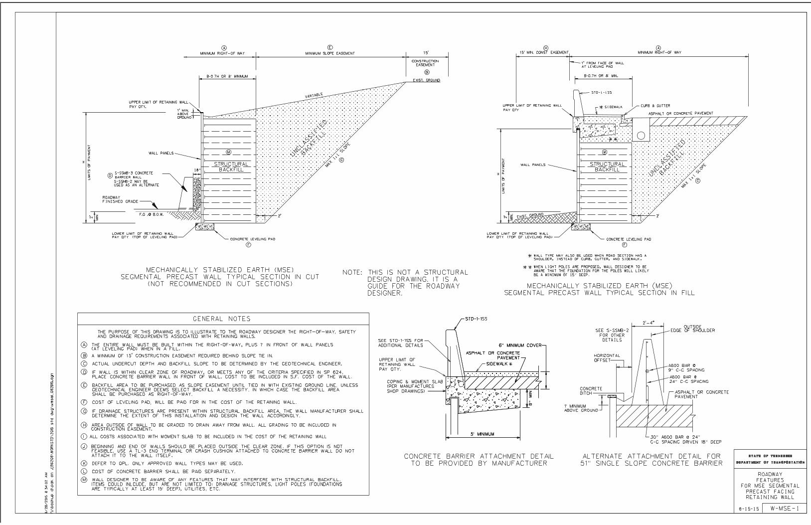
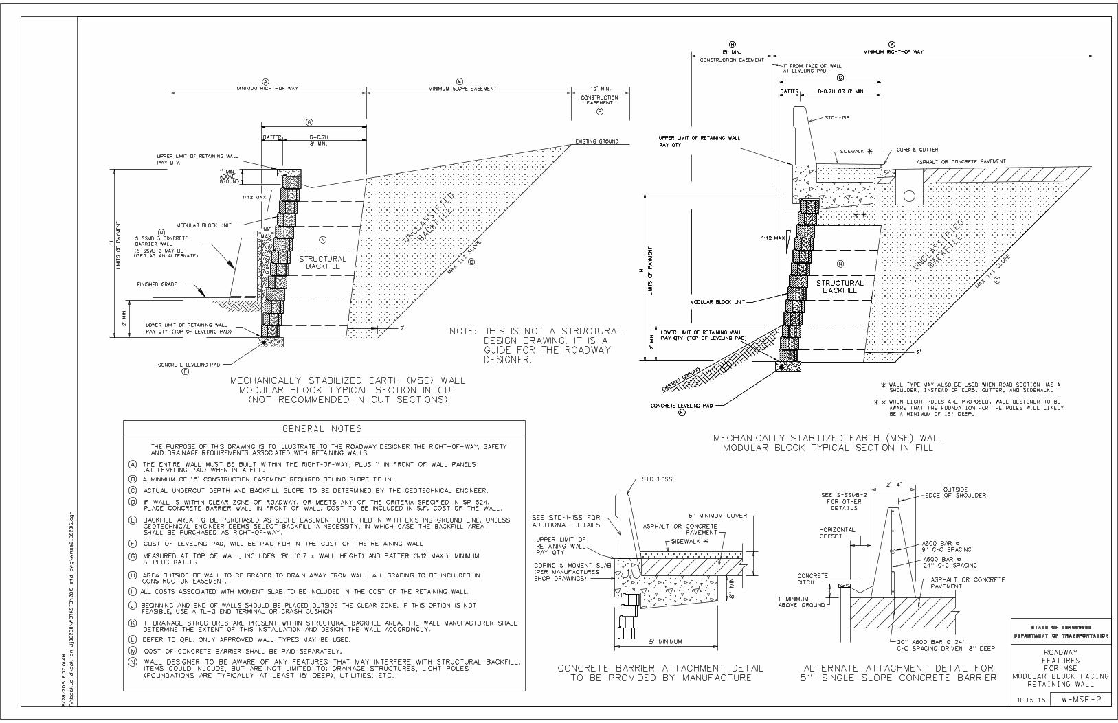
Method of Measurement
The method of measurement shall be square foot area of the wall face, measured from the top of footing (or bottom of wall for walls without footings) to the top of the wall excluding any appurtenances in accordance with drawing number W-MSE-1 (in this document). Appurtenances are defined herein as barriers, fences, sign supports, noise wall support posts, and other fixtures. Coping, caps, end sections and moment slabs will not be considered appurtenances and are to be considered as part of the wall face.
Basis of Payment
The earth retaining wall, complete in place and accepted, shall be paid for at the contract square foot bid price. The bid price for walls shall include as required: grading and compaction of the wall foundation, undercutting and backfilling of weak surficial zones, installation of ground improvement, footing excavation, presplitting, sheeting, shoring, drilling, piles, lagging, grouting, concrete, reinforcing steel, reinforcement strips or mesh, tie strips or rods, fasteners, connectors, wire mesh baskets, prefabricated modular components, post tensioning, performance testing and evaluation, architectural treatment and/or texture finish, drainage system, water-stops and joint sealing material, coping, caps, end sections, moment slabs, and all miscellaneous material and labor for the complete installation of the wall. If the contractor's design requires the use of select granular backfill, the unit price bid for the wall shall be full compensation for any additional backfill costs due to the use of select backfill material.
If required for retaining wall protection against vehicle impact, the cost of the barrier wall and end terminals shall be included in the square foot cost of the wall.
Additional area of wall required due to unforeseen foundation conditions or other reasons and approved by the Engineer will be paid for on the basis of the unit price bid except as noted below.
The mechanically stabilized earth wall, complete in place and accepted as noted above, shall be paid for at the contract square foot bid price. No increase in unit price will be
SP624 SP624
Page 8 of 69
paid for increases in wall height less than or equal to 10 feet as compared to the contract plans and wall heights. Wall height increases greater than 10 feet will be paid for by supplemental agreement.
The cast-in-place concrete cantilever or counterfort retaining wall, complete in place and accepted shall be paid for at the contract square foot bid price except as noted below.
If the actual driven quantity of concrete piles varies more than 10% from the estimated quantity based on the estimated lengths, an increase or decrease based on the contract bid price, or in the absence of a bid item, a price of twenty eight (28) dollars, per linear foot of additional or reduced pile length will be added or deducted accordingly from the price paid for the retaining wall. If the Engineer orders additional test piles, they will be paid for at the contract bid price, or in the absence of a bid item, a price of forty (40) dollars per linear foot. If the contractor changes friction pile types or sizes, additional load test(s) may be required at the Engineer’s discretion and at the contractor's expense.
If the contractor uses a different type of pile than those that have estimated lengths shown on the contract plans, the price of the wall shall include all costs associated with piles and pile installation with no additional payment for any variation in pile lengths. All pile types and pile driving procedures, lengths, and bearings shall be in accordance with the Standard Specifications and shall be approved by the Engineer
The contractor shall show the estimated quantity of point bearing steel piles on the design drawings submitted for approval. If the actual quantity of steel piles driven differs more than 10% from this approved quantity because of variation in the rock line, the cost of the retaining wall will be increased or decreased accordingly based on the contract bid price, or in the absence of a bid item, a unit price of thirty five (35) dollars per linear foot, for the adjusted piling quantity.
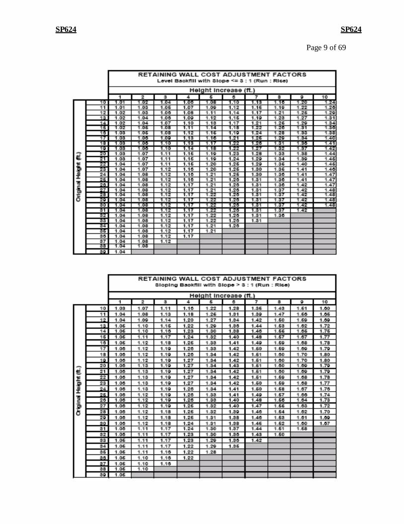
If the Engineer orders changes in the work which alters the exposed surface area of the wall without increasing the height of the wall, payment will be increased or decreased accordingly based on the square foot bid price. If the Engineer orders changes in the work which increases the height of the wall, the unit price bid for the wall sections that were increased up to a maximum of 10 feet will be adjusted according the following tables. Adjustments exceeding 10 feet will be made by supplemental agreement.
SP624 SP624
Page 9 of 69
SP624 SP624
Page 10 of 69
Specific Wall Construction and Materials Requirements
A. Cast-in-Place (CIP) Concrete Gravity Retaining Walls
1. Construction
The construction of the wall shall be in accordance with this Special Provision and the Standard Specifications.
B. Cast-In-Place (CIP) Concrete Cantilever And Counterfort Retaining Walls
1. Construction
The construction of the wall shall be in accordance with this Special Provision and the Standard Specifications. If the use of piles is anticipated, the foundation information shown on the contract plans shall include the skin friction (Fs) and end bearing (Qb) values, or the location of the rock line. Based on this information, estimated pile lengths shall be shown on the contract plans for fifty (50) and one hundred (100) tons ultimate bearing capacity for Size 1 concrete friction piles. The contractor shall estimate point bearing steel pile refusal lengths based on the given rock line information.
Concrete friction piles shall be installed to provide a minimum factor of safety of 2.0 if a load test is used and a minimum factor of safety of 3.0 if a load test is not used. Pile types, load test procedures, and driving equipment shall be in accordance with the Standard Specifications and shall be approved by the Engineer. The number and location of test piles and load tests shall be approved by the Engineer. Test pile lengths shall be ten (10) feet longer than the estimated pile lengths. Test piles shall be driven in accordance with the Standard Specifications, and shall be required at least every fifty (50) feet along the wall, unless otherwise approved by the Engineer. No pile shall be any farther than five hundred (500) feet from a load test, if a load test is used, unless otherwise approved by the Engineer. The length of production piles to be driven and the required bearing based on the driving equation shall be determined by the Engineer based on the required design bearing, the results of the test piles and load tests (if used), and applicable safety factors. Driven pile lengths and final bearings shall be approved by the Engineer. Point Bearing Steel Piles shall be driven to refusal. Pile tips shall be used when indicated on the contract plans. All reinforcing steel projecting from footing into the wall in the back face (fill side) shall be epoxy coated.
C. Concrete Crib Walls (See QPL 38 for Approved Manufacturer/Supplier)
1. Materials
The following items are the construction materials requirements necessary for crib wall design fabrication. All materials shall be approved prior to use. • Pre-Cast Concrete Crib Units
The pre-cast crib units are to be made of Class D Portland cement concrete conforming to Section 604 of the Standard Specifications.
SP624 SP624
Page 11 of 69
• Crib Backfill
All backfill material shall be tested prior to use and at the established frequencies in the TDOT “Procedures for the Sampling and Testing, and Acceptance of Materials and Products (SOP 1-1)”.
o The crib backfill material shall consist of an AASHTO classified A-1-a, A-1-b, or A-3 soil with the additional requirement no more than ten percent by weight pass the #200 sieve.
o The unit weight of the crib fill should be a minimum 115 lb. per cubic foot.
o Filter protection (geotextile) may be required.
• Backfill Behind the Crib Type Structure
All backfill material shall be tested prior to use and at the established frequencies in the TDOT “Procedures for the Sampling and Testing, and Acceptance of Materials and Products (SOP 1-1)”.
o If a filter blanket is placed behind the wall, native soil may be used as backfill behind the structure.
o Select fill, as defined in 4.2.1 of this document, can be used as backfill behind the structure. The backfill unit weight must be a minimum of 115 pcf. An internal angle of friction can be assumed equal to 35 degrees.
2. Fabrication of Precast Concrete Crib Units
• All pre-cast concrete shall be produced in an approved plant in accordance with the TDOT Procedure for the “Manufacture and Acceptance of Pre- cast Concrete Drainage Structures, Noise Wall panels, and Retaining wall panels”.
Out-of-state producers shall provide documentation of material quality before the manufacture of any pre-cast products (i.e. aggregate quality reports, cement/steel mill test reports, etc.)
The fabricator shall provide two precast modular units to the Engineer for approval.
o These approved precast modular units will serve as standard models. The finished exposed faces of the production precast modular units should be similar to the exposed faces of the model precast modular units.
o One of the model precast modular units should be kept at the production plant for relative comparison to future modular units. The other model should be kept on the construction site for comparison to the other delivered units.
• To assure uniform unit production steel forms must be used.
• The placement of reinforcing steel within the precast units should conform to the design placement shown in the shop drawings.
Page 12 of 69
SP624 SP624
• Final acceptability of the precast units shall be determined on the basis of
compression tests, production defects and tolerances, and visual inspection. The manufacturer shall furnish all sampling and testing facilities.
• Section 604 of the Standard Specifications states the units shall be steam or moist cured until developing the specified compressive strength set forth in the shop drawings. Any unit not developing the specified compressive strength shall be rejected.
• The precast units should not be delivered before samples have attained the required compressive strength of 4,000 psi (f’c).
• Prior to shipment, the finished units are subject to visual inspection by the Engineer. Individual crib units may be rejected for any of the reasons listed below.
i. Variations in the exposed face texture relative to the approved model face texture.
ii. The length or height of the unit not satisfying the unit allowable tolerance limit of 3/16”.
iii. Honeycombed o r o p e n t e x t u r e u n i t s w h i c h a r e n o t p r o p e r l y repaired.
iv. Individual defects which could affect the structural integrity of the unitVariations in the exposed face texture relative to the approved model face texture.
• TDOT will verify products before shipment in accordance with the TDOT
Procedure for the “Manufacture and Acceptance of Pre-cast Concrete Drainage Structures, Noise Wall panels, and Retaining wall panels”. If products are manufactured out of state, TDOT may verify at the project site PRIOR to the placement of the units. The Contractor, or producer, shall notify the Regional Materials and Tests Division that products need to be verified.
• Upon delivery, the exposed surface of the precast units shall be examined. If the exposed faces of any of the units are below the standards of the approved model on site, the units shall be replaced or properly repaired until conforming to the appearance, strength, and durability of the approved model.
• The date of manufacture shall be clearly and permanently marked on one of the inside surfaces of each unit. Each shipment must be accompanied with a certification letter as stated in the TDOT Procedure for the “Manufacture and Acceptance of Pre-cast Concrete Drainage Structures, Noise Wall panels, and Retaining wall panels.
3. Construction
• The Contractor should perform any soil improvement, such as undercutting and backfilling before foundation preparation.
Page 13 of 69
SP624 SP624
• Compact the top 12” of soil on which the structure will rest to at least 95% of the maximum laboratory dry density as specified in AASHTO T-99.
• No Crib-type wall should be built upon frozen ground.
• Following excavation for the crib wall system, the Contractor shall notify the Engineer for approval of the footing depth and character of the foundation material. No crib wall system work shall proceed until approval has been granted.
• The correct batter of the wall shall not exceed ½” per 10 ft. of wall height.
• The crib backfill should be placed and compacted to at least 95% of the maximum laboratory dry density (AASHTO T-99) in layers no thicker than 12”.
• Backfilling behind the crib system shall follow erection as closely as possible. The wall height should never be greater than three feet above the backfill.
• Any underdrain shall be placed in accordance with the details of the working plans.
• The Contractor shall furnish, install, operate, and maintain satisfactory dewatering systems as required to maintain the site in a dry and workable condition. These systems shall be continued as long as necessary. No separate measurement or payment will be made for dewatering.
D. Bin Wall (See QPL 38 for Approved Manufacturer/Supplier)
1. Materials
• Filler for horizontal joints between modular units shall be resin-bonded cork filler or closed cell foam, cross linked polyethylene polymer, conforming to test requirements of AASHTO M 153 or ASTM D 1752 (Type II) or equal. Filter fabric placed behind front vertical joints shall be at least 6” wide and conform to section 918.27 of the TDOT Standard Specifications).
• Backfill: All select granular material shall be free from shale and organic or otherwise deleterious material and conform to the following gradation limits:
Sieve Size Percent Passing 6 inch 100 3 inch 75-100 No. 200 0-15
The Contractor, at his option, may produce the select granular material by processing the excavation from the project or from approved material from other sources. No direct payment will be made for producing the select granular material.
All backfill material shall be tested prior to use and at the established frequencies in the TDOT “Procedures for the Sampling and Testing, and Acceptance of Materials and Products (SOP 1-1)”.
Page 14 of 69
SP624 SP624
• Bearing pads shall be rubber of size, and manufacture shown on shop drawings, with the following properties perpendicular to the pad thickness:
i. Compression- minimum ultimate strength 8000 psi ii. Initial Cracking Strain- 40% of thickness
iii. Hardness (Shore A) – 75 +/- 5 iv. Tensile Strength- ASTM D 412, die “C”, 1000 psi +/- 100 psi v. Tear Strength- ASTM D 624, die “B” – 360 psi minimum
• Acceptance of materials furnished for work will be in accordance with the TDOT “Procedures for the Sampling and Testing, and Acceptance of Materials and Products (SOP 1-1) and certified test reports as specified in Section 106 – Control of Materials supplemented by routine tests run by the Department as defined in the various applicable sections of the Standard Specifications.
2. Construction • Bin Fabrication
o All pre-cast concrete shall be produced in an approved plant in accordance with the TDOT Procedure for the “Manufacture and Acceptance of Pre-cast Concrete Drainage Structures, Noise Wall panels, and Retaining wall panels”.
Out-of-state producers shall provide documentation of material quality before the manufacture of any pre-cast products (i.e. aggregate quality reports, cement/steel mill test reports, etc.)
Before proceeding with production, a model precast modular unit shall be provided by the fabricator for the Engineer’s approval to establish a guide and standard for the type of finish to be furnished on the exposed face. This model shall be kept at the fabricator’s plant to be used for comparison purposes during production. Formed surfaces other than the exposed face shall not require a special finish
o Forms: Forms for the units shall be constructed of steel with dimensional tolerances that will assure the production of uniform units. Finish for the front face of the wall shall be in accordance with the finish specified on the contract plans.
i. Mixing and Placing Concrete: The concrete mix as designed shall be proportioned and mixed in a batch mixer to produce a homogeneous concrete. The transporting, placement, and compaction of concrete shall be by methods that will prevent segregation of the concrete materials and the displacement of the reinforcement steel from its proper position in the form. Concrete shall be carefully placed in the forms and vibrated sufficiently to produce a surface free from imperfections such as honeycomb, segregation or cracking. Clear form oil of the same manufacture shall be used throughout the casting operation.
ii. Reinforcing Steel: All reinforcing steel for the precast modules and other components shall be fabricated and placed in accordance with plans and Standard Specifications.
Page 15 of 69
SP624 SP624
o Testing and Inspection: Acceptability of the precast units at the casting yard shall be determined on the basis of compression tests and visual inspection during casting. The manufacturer shall furnish such facilities and assistance as is required to carry on the sampling and testing in an expeditious and satisfactory manner. The manufacturer shall document and provide all test data and certify in accordance with the TDOT Procedure for the “Manufacture and Acceptance of Pre-cast Concrete Drainage Structures, Noise Wall panels, and Retaining wall panels”.
iii. Curing: The units shall be steam or moist cured as specified in Section 604 of the Standard Specifications for a sufficient length of time so that the concrete will develop the specified compressive strength. Any panel which does not reach specified strength within 28 days shall be rejected.
o Compressive Strength: Compressive tests to determine the minimum strength requirements shall be made on cylinders. A minimum of six cylinders for determining when the units may be put into service will be made from each day’s production and cured in accordance with AASHTO T 23 or ASTM C 31. The 28 day compressive strength shall be at least 5000 psi. Compressive strength tests shall be in accordance with AASHTO T 22 or ASTM C 39.
o Rejection: The quality of materials, the process of manufacture, and the finished units shall be subject to inspection by the Engineer prior to shipment. Precast units may be subject to rejection on account of failure to conform to the requirements set forth herein. Individual units may be rejected because of any of the following:
• Variations in the exposed face that substantially deviate from the approved model as to texture in accordance with precast concrete industry standards.
• Dimensions not conforming to the following tolerances:
o Face of panel, length or height: plus/minus 3/16” o Deviation from square when measured on diagonal:
5/16” for modules up to 10’ wide, 3/4” for larger units.
• Honeycombed or open texture not properly repaired.
• Defects which would affect the structural integrity of the unit.
o Shipment: The precast units shall not be shipped until they have achieved the required concrete strength (f’c) of 5000 psi. TDOT will verify products before shipment in accordance with the TDOT Procedure for the “Manufacture and Acceptance of Pre-cast Concrete Drainage Structures, Noise Wall panels, and Retaining wall panels”. If products are manufactured out of state, TDOT may verify at the project site PRIOR to the placement of the units. The Contractor, or producer, shall notify the Regional Materials and Tests Division that products need to be verified
Page 16 of 69
SP624 SP624
o Repairs at Plant: Before shipment, surfaces of all precast units shall be examined. If the exposed face of a unit is below the standard of the approved model then it shall be properly repaired to conform to the balance of the work with respect to appearance, strength and durability.
o Handling and Storage: Handling devices, as required, shall be provided in each precast modular unit for the purpose of handling and placing. Care shall be taken during storage, transporting, hoisting and handling of all units to prevent cracking or damage. Units damaged by improper storing, transporting or handling shall be replaced or repaired to the satisfaction of the Engineer.
o Marking: The date of manufacture and production lot number shall be clearly and permanently marked on the rear face of each unit.
• Erection:
i. Foundation Preparation: The foundation for the bin wall shall be graded to the elevations and dimensions shown on the contract plans. Prior to wall construction, the top 12 inches of the foundation shall be compacted to at least 95% of the maximum laboratory dry density as determined by AASHTO T 99. Any foundation soils found to be unsuitable or incapable of sustaining the required compaction shall be removed and replaced. After the excavation for each location of the bin wall has been performed, the Contractor shall notify the Engineer. No concrete leveling footing shall be placed until the depth of excavation and the character of the foundation material has been approved by the Geotechnical Engineering Section of the Division of Materials and Tests and permission has been given to proceed by the Engineer.
ii. At each unit foundation level, either a precast or cast-in-place footing and/or leveling pad shall be provided as shown on the shop drawings. The footings shall be given a wood float finish and shall reach the required compressive strength of 3000 psi, before placement of wall modules. The completed footing surface shall be constructed in accordance with grades and cross slopes shown on the shop drawings. When tested with a 10’ straight edge, the surface shall not vary more than 1/8” in 10’. Any additional depth of footing required to level the top surface and bear on approved foundations shall be at the Contractor’s expense.
iii. The modular units shall be installed in accordance with the manufacturer’s recommendations. Special care shall be taken in setting the bottom course of units to true line and grade. Joint filler and neoprene pads, when required, shall be installed in the horizontal joints. Joints at corners or angle points shall be closed as shown on the plans or in accordance with recommendation of the manufacturer.
Page 17 of 69
SP624 SP624
iv. All units above the first course shall interlock with the lower courses. Vertical joints shall be staggered with each successive course, or as shown on shop drawings. The vertical joint opening on the front face of the wall shall not exceed 3/4".
v. The interior of each successive course of precast modular units shall be filled with select granular backfill. The maximum lift thickness shall be 2 feet, and shall then be thoroughly consolidated with a vibratory tamping device.
vi. Backfill behind the wall shall be compacted to at least 95 percent of the maximum laboratory dry density as defined in AASHTO T 99 to within one foot of the top of the wall. The top 12 inches shall be compacted to at least 100 percent of the maximum laboratory dry density.
vii. When erecting a battered wall, placement of backfill behind the wall shall closely follow erection of successive courses of units. At no time shall the difference in elevation between the backfill and the top of the last erected course exceed seven feet.
viii. The overall vertical tolerance of the wall shall not exceed 1/2 inch per 10 feet of wall as shown per plans.
ix. Underdrain, if required, shall be placed in accordance with the details shown on the plans or shop drawings.
x. Storm Drains: Where required, precast concrete wall units shall be provided with the appropriate storm drain openings cast into units at the appropriate elevation and locations indicated on drainage profiles. Catch basins shall be located so pipes will enter perpendicular (plan view) to the precast wall units or below the leveling footing as shown on the plans. Construction of catch basins and placement of storm drains must be coordinated with the bin wall construction.
xi. Cooperation between contractors: Contractors must coordinate all phases of the work to prevent delays and expedite construction.
xii. Dewatering: The Contractor shall furnish, install, operate, and maintain satisfactory dewatering systems as required to maintain the site in a dry and workable condition so as to permit grading and compaction of the wall foundation and proper erection and backfill of the wall. These systems shall include all equipment and materials, and shall be continued as long as necessary. No separate measurement or payment will be made for dewatering.
xiii. Technical Consultations: The fabricator will be required as a part of the contract to provide onsite technical expertise to the Contractor and/or the State upon request. Response to requests shall be required within five (5) days of the request. The cost of
SP624 SP624
Page 19 of 69
furnishing such technical consultations shall be at no cost to the State.
• On Site Inspection The quality of materials, the process of manufacture, and the finished member shall be subject to inspection and approval by the Engineer. Any bin wall units damaged prior to acceptance shall be repaired or reconstructed as directed by the Engineer. All costs of repairs or reconstruction shall be at the Contractor’s expense.
E. Gabion Wall (See QPL 38 for Approved Manufacturer/Supplier)
1. General:
This section covers the furnishing, assembling, filling with stone and tying open wire mesh rectangular compartmented gabions placed on filter cloth or filter stone as specified herein, and in reasonably close conformity with the lines, grades, dimensions, and cross-sections shown on the plans or as directed by the Engineer, and the design, working drawings, materials, construction, measurement and payment for gabions. Included in the scope of this section are: grading and compaction of the wall foundation, general and local dewatering as required for proper execution of the work, installation of wall drainage systems as specified on the plans, erection of units, the placement of stone within the units and compaction of the soils behind the units as well as the construction of any required reinforced concrete appurtenances such as caps, copings, or end sections as specified on the plans. For the purposes of this section, the gabions foundation shall include all areas underlying the gabion wall. All other items included in the construction of the retaining wall not specifically mentioned herein this manual shall conform to the applicable sections of the Tennessee Department of Transportation Standard Specifications for Road and Bridge Construction, January 1, 2015 and the current AASHTO LRFD Bridge Design Specifications with interims. Future reference to the Tennessee Department of Transportation Standard Specification For Road And Bridge Construction- January 1, 2015 will be made as Standard Specifications.
2. Design Criteria The current AASHTO LRFD Bridge Design Specifications with interims shall be used as the basis for design for the Gabion Wall utilized as a gravity type retaining wall.
3. Submittals Working drawings and design calculations shall be submitted to the Engineer for review and approval at least 60 days before wall construction is to begin. See Chapter I, Section 4.0 for contractor/supplier submittal responsibilities. The Contractor shall not start work on the bin wall until the working drawings have been approved by the Engineer. Approval of the Contractor’s working drawings shall not relieve the Contractor of any responsibility under the contract for the successful completion of the work.
4. Materials • Gabion Wire Mesh
SP624 SP624
Page 20 of 69
Gabion basket units shall be fabricated from either a double twisted hexagonal wire mesh (metallic or PVC coated as required in contract plans) or welded wire mesh (metallic or PVC coated as required in contract plans) that meets property requirements described in:
ASTM Designation: A974 − 97 (Reapproved 2011) Standard Specification for Welded Wire Fabric Gabions and Gabion Mattresses (Metallic-Coated or Polyvinyl Chloride (PVC) Coated)
ASTM Designation: A975 − 11 Standard Specification for Double–Twisted Hexagonal Mesh Gabions and Revet Mattresses (Metallic-Coated Steel Wire or Metallic-Coated Steel Wire With Poly(Vinyl Chloride) (PVC) Coating
All other components of the gabion construction such as selvedge wire, lacing wire, spiral connectors, clips, galvanization, PVC coating shall be in accordance with the above specifications.
• Stone Fill
All stone fill shall be approved by the Engineer and shall be of suitable quality to ensure durability. When the stone is subjected to five alterations of sodium sulfate soundness testing, in accordance with AASHTO T-104, the weighted percentage of loss shall not be more than twelve percent. The inclusion of objectionable quantities of shale, dirt, sand, clay, rock fines, and other deleterious material will not be permitted. Stone fill shall be of well-graded mixture with sizes ranging between 4 inches and 10 inches in diameter, based on U.S. Standard square mesh sieves. No stone shall have minimum dimension less than 4 inches. Stone fill material selected for use in the gabions shall meet the minimum in-place density specified on the plans.
• Filter Cloth
All filter cloth shall meet the applicable requirements of Section 918.27, Sub- Section 27, of the Standard Specifications.
• Filter Stone
All filter stone shall meet the applicable requirements of Grading Size 68 or 57. See the Standard Specifications section 903.22.
5. Construction • Clearing and Grubbing
Clearing and grubbing, removal of structures and obstructions, and excavation and undercutting shall be performed in accordance with the provisions of Sections 201, 202, and 203, respectively, of the Standard Specifications. Cost of these items, however, shall be included in the square foot price bid retaining walls as shown in contract plans.
SP624 SP624
Page 21 of 69
• Foundation Preparation
Foundation preparation for the gabions shall be made to the required depth below the finished surface and to such a width as to permit the proper installation of the gabions. Prior to wall construction, the top 12 inches of the foundation shall be compacted to at least 95% of maximum laboratory dry density as specified in AASHTO T 99. All soft and unsuitable material shall be removed and replaced with suitable material, which shall then be compacted. The finished subgrade shall be smooth and uniform, with no protruding debris or rock formations. A Size 57 stone may be required to obtain the smooth uniform surface and shall be in reasonably close conformity with the dimensions and designs shown on the plans or established by the Engineer. No gabions shall be constructed upon frozen foundation material.
• Filter Cloth or Filter Stone
Upon final foundation preparation and acceptance by the Engineer, the filter cloth or filter stone shall be placed directly on the foundation at those locations shown on the plans or as directed by the Engineer. All end and side laps shall be a minimum of 18 inches for the filter cloth.
• Assembly (Fabrication)
Gabions shall be fabricated in such a manner that the sides, ends, lid, and diaphragms can be assembled at the construction site into rectangular baskets. Gabions shall be of single unit construction, i.e., the base, lid, ends, and sides shall be either woven into a single unit or one edge of these members connected to the base section of the gabion in such a manner that strength and flexibility at the point of connection is at least equal to that of the mesh. Gabion units shall be equally divided, by diaphragms of the same mesh and gauge as the body of the gabions, into cells whose length does not exceed the horizontal width. The gabion shall be furnished with the necessary diaphragms secured in proper position on the base in such a manner that no additional tying at this juncture will be necessary. All perimeter edges of the mesh forming the gabion shall be securely joined so that the joints formed by tying the selvedges or installation of spiral ties have at least the same strength as the body of the mesh. Lacing wire or connecting wire shall be supplied in sufficient quantity for securely fastening all diaphragms and edges of the gabion.
• Assembly (Field)
i. Empty gabion units shall be placed on the filter blanket when required on contract drawings and shall be assembled individually to the lines and grades indicated on the Plans. Or as directed by the Engineer, with the sides, ends, and diaphragms erected in such a manner to ensure the correct position. All adjoining empty gabion units must be connected by tie wire lacing along the perimeter of their contact surfaces in order to obtain a monolithic structure. Lacing of adjoining basket units shall be accomplished by continuous stitching with alternating
SP624 SP624
Page 22 of 69 single and double loops at intervals of not more than 5 inches. All lacing wire terminals shall be securely fastened. The use of expedient clip connections for this purpose or as final lid closing will not be permitted. After adjoining empty basket units are set to line and grade and common sides with adjacent units thoroughly laced, they shall be placed in tension and stretched to remove any kinks from the mesh and to a uniform alignment. The stretching of empty basket units shall be accomplished in such a manner as to prevent any possible unraveling and distortion.
ii. Stone filling operations shall carefully proceed with placement by hand or machine so as not to damage galvanized wire coating, to assure a minimum of voids between the stones, to prevent damage to the underlying filter blanket, and to ensure the maintenance of alignment throughout the filling process. The maximum height from which the stone may be dropped into the basket units shall be 36 inches. Along all exposed faces, the outer layer of stone shall be carefully placed and arranged by hand to ensure a neat and compact appearance. The last layer of stone shall be leveled with the top of the gabions to allow for the proper closing of the lid and to provide an even surface that is uniform in appearance.
iii. Lids shall be stretched tight over the stone fill using crowbars or lid closing tools until the lid meets the perimeter edges of the front and end panels. The lid shall then be tightly laced with tie wire along all edges, ends and internal cell diaphragms by continuous stitching with alternating single and double loops at intervals of not more than 5 inches. Special attention shall be given to see that all projections or wire ends are turned into the baskets. Where shown on the drawings or as directed by the Engineer, or where a complete gabion unit cannot be installed because of space limitations, the basket unit shall be cut, folded and wired together to suit existing site conditions. The mesh must be cleanly cut and the surplus mesh cut out completely or folded back and neatly wired to an adjacent gabion face. The assembling, installation, filling, lid closing, and lacing of the reshaped gabion units shall be carried out as specified above.
• Backfill
Backfilling of the gabion wall shall follow erection as closely as possible and in no case should the height of the wall be greater than seven feet above the backfill. Underdrains, if required, shall be placed in accordance with the details shown on plans. Gabion walls backfill shall have a density of 100 pounds per cubic foot or as specified on contract plans and shall be compacted to at least 95 percent of the maximum laboratory dry density as defined in AASHTO T 99 to within one foot of the top of the wall. The top 12 inches shall be compacted to at least 100 percent of the maximum laboratory dry density. The backfill material shall consist of broken or crushed stone, gravel, sand, slag or other suitable coarse granular material to insure proper drainage. Shale, clay or cinders shall not be permitted as
SP624 SP624
backfill material. Prior to placement, the backfill material must be approved by the Engineer. The Contractor shall furnish, install, operate, and maintain satisfactory dewatering system as required to maintain the site in a dry and workable condition so as to permit grading and compaction of the wall foundation and proper erection and backfill of the wall. These systems shall include all equipment and materials, and shall be continued as long as necessary. No separate measurement or payment will be made for dewatering or dewatering systems.
All backfill material shall be tested prior to use and at the established frequencies in the TDOT “Procedures for the Sampling and Testing, and Acceptance of Materials and Products (SOP 1-1)”.
• Vertical Wall Tolerance
The overall vertical tolerance of the wall (plumbness from top to bottom) shall not deviate more than ½ inch per 10 feet of wall height from the contract drawings batter of the wall.
• On Site Inspection
The quality of materials, the process of manufacture, and the finished members shall be subject to inspection and approval by the Engineer. Any gabions damaged prior to acceptance shall be repaired or reconstructed as directed by the Engineer. All costs of repairs or reconstruction shall be at the Contractor’s expense.
F. Segmental, Precast Facing Mechanically Stabilized Earth (MSE) Wall (See QPL 38 for Approved Manufacturer/Supplier)
1. Materials
General - The Contractor shall make arrangements to purchase or manufacture the facing elements, reinforcing mesh or strips, attachment devices, joint filler, and all other necessary components. Materials not conforming to this section or the Standard Specifications or from sources not listed in the contract document shall not be used without written consent from the Engineer. Out-of-state producers shall provide documentation of material quality before the manufacture of any pre-cast products (i.e. aggregate quality reports, cement/steel mill test reports, etc • Reinforced Concrete Facing Panels - The panels shall be fabricated in
accordance with the TDOT Procedure for the “Manufacture and Acceptance of Pre-cast Concrete Drainage Structures, Noise Wall panels, and Retaining wall panels.”
i. Acceptability of the precast units will be determined on the basis of compressive strength tests, production tolerances, and visual inspection. The Contractor, or the supplier, shall furnish facilities and perform all necessary sampling and testing in an expeditious and satisfactory manner as directed by the Engineer.
ii. The Portland cement shall be types 1, 2, or 3 and shall conform to the requirements of AASHTO M 85 (ASTM C 150). Concrete for precast panels shall be Class D (4000 psi) as specified in Section 604 of the TDOT Standard Specifications. Admixtures containing chlorides shall not be used.
iii. The panels shall be cast using steel forms. The front face of the
SP624 SP624 panel (face exposed to view when installed in the wall) shall be cast against a steel form or architectural form liner. The back face is to be float finished. The concrete in each panel shall be placed without interruption and shall be consolidated by the use of an approved vibrator, supplemented by such hand tamping as may be necessary to force the concrete into the corners of the forms and prevent the formation of stone pocket or cleavage planes. Clear form oil of the same type shall be used throughout the casting operation.
iv. Unless otherwise indicated on the plans or elsewhere in the Standard Specifications, the concrete surface for the front face shall have a Class 1 finish as defined by Section 8.12 of AASHTO, Division II, and for the rear face a uniform surface finish. The rear face of the panel shall be float finished sufficiently to eliminate open aggregate pockets and surface distortions in excess of 1/4 inch. The panels shall be cast on a flat area. The strips or other galvanized attachment devices shall not contact or be attached to the face panel reinforcement steel.
v. Curing and forms removal shall be in accordance with the requirements of Section 604.20 and 604.24 of the Standard Specifications, unless otherwise approved by the Engineer. The forms shall remain in place until they can be removed without damage to the panel.
vi. The units shall be fully supported until the concrete reaches a minimum compressive strength of 1000 psi. The units may be shipped after reaching a minimum specified compressive strength of 4000 psi. TDOT will verify products before shipment in accordance with the TDOT Procedure for the “Manufacture and Acceptance of Pre-cast Concrete Drainage Structures, Noise Wall panels and Retaining wall panels”. If products are manufactured out of state, TDOT may verify at the project site PRIOR to the placement of the units. The Contractor, or producer, shall notify the Regional Materials and Tests Division that products need to be verified.
vii. Marking - The date of manufacture, the production lot number, and the piece mark shall be clearly scribed on an unexposed face of each panel.
viii. Handling, Storage, and Shipping - All units shall be handled, stored, and shipped in such a manner as to eliminate the dangers of chipping, discoloration, cracks, fractures, and excessive bending stresses. Panels damaged during handling or storage at the casting plant shall be repaired at the plant as directed by the Engineer. Any panels damaged during handling, storing, or shipping may be rejected upon delivery at the option of the Engineer. Panels in storage shall be supported in firm blocking located immediately adjacent to embedded connection devices to avoid bending the connection devices.
ix. Tolerances - All units shall be manufactured within the following tolerances:
SP624 SP624 • Panel Dimensions - Position panel connection devices within 1
inch, except for all other dimensions within 3/16 inch. • Panel Squareness - Squareness as determined by the difference
between the two diagonals shall not exceed 1/2 inch. • Angular distortion with regard to the height of the panel shall
not exceed 3/16 inch in 5 feet. • Panel Surface Finish - Surface defects on smooth formed
surfaces measured over a length of 5 feet shall not exceed 1/8 inch. Surface defects on the textured-finish surfaces measured over a length of 5 feet shall not exceed 5/16 inch.
x. Steel - In accordance with the Standard Specifications.
xi. Compressive Strength - Acceptance of the concrete panels, with respect to compressive strength, will be determined on the basis of production lots. A production lot is defined as a group of panels that will be represented by a single compressive strength sample and will consist of a single day’s production as defined in the certify in accordance with the TDOT Procedure for the “Manufacture and Acceptance of Pre-cast Concrete Drainage Structures, Noise Wall panels, and Retaining wall panels”.
xii. During the production of the concrete panels, the Engineer will sample the concrete in accordance with AASHTO T 141 (ASTM C 172). A single compressive strength sample, consisting of a minimum of six (6)cylinders, will be randomly selected for every production lot.
xiii. Cylinders for compressive strength tests shall be prepared in accordance with AASHTO T 23 (ASTM C 31) on 6" x 12" or 4” x 8” specimens. For every compressive strength sample, a minimum of two (2) cylinders will be cured in the same manner as the panels and tested for acceptance no later than twenty-eight (28) days. The average compressive strength of these two cylinders, when tested according with AASHTO T 22 (ASTM C 39), will determine the compressive strength of the production lot.
xiv. If the Contractor wishes to remove forms or ship the panels prior to 28 days, a minimum of two (2) additional cylinders will be cured in the same manner as the panels. The average compressive strength of these cylinders when tested in accordance with AASHTO T 22, will determine whether the forms can be removed and the panels are acceptable.
xv. Acceptance of a production lot will be made if the compressive strength test result is greater than or equal to 4,000 psi when tested for acceptance no later than 28 days.
xvi. In the event that a production lot fails to meet the specified
compressive strength requirements, the production lot shall be rejected. Such rejection shall prevail unless the manufacturer, at their own expense, obtains and submits cores for testing and the results show that the strength and quality of the concrete placed within the panels of the production lot is acceptable. The cores shall be taken from the panels within the production lot and tested in accordance with the specifications of AASHTO T 24 (ASTM
SP624 SP624 C 42). Two cores per each cylinder that failed will be required. In addition, any or all of the following defects shall be sufficient cause for rejection:
• Defects that indicate imperfect molding.
• Defects indicating honeycombing or open texture concrete.
• Defects in the physical characteristics of the concrete such as cracked or severely chipped panels.
• Color variation on front face of panel due to excess form oil or other reasons.
• Damage due to handling, storing or shipping.
xvii. The Engineer shall determine whether spalled, honeycombed, chipped or otherwise defective concrete shall be repaired or rejected. Repair of concrete, if allowed, shall be done with a TDOT approved cementitious polymer patching mortar in a manner satisfactory to the Engineer. Repair to concrete surface which will be exposed to view after completion of construction must be approved by the Engineer.
• Soil Reinforcing and Attachment Devices - All reinforcing and attachment devices shall be shop fabricated and carefully inspected to ensure they are true to size and free from defects that may impair their strength and durability.
i. Reinforcing Strips - Reinforcing strips shall be hot rolled from bars to the required shape and dimensions. Their physical and mechanical properties shall conform to either AASHTO M 183 (ASTM A 36) or AASHTO M 223 (ASTM A 572) grade 65 or equal. Galvanization shall conform to the minimum requirements or AASHTO M 111 (ASTM A 123).
ii. Tie Strips - The tie strips shall be shop- fabricated of hot rolled steel conforming to the minimum requirements of ASTM 570, Grade 50 or equivalent. Galvanization shall conform to AASHTO M 111 (ASTM A 123). Tie straps may be partially bent before shipment to the precast yard. Minimum bending radius shall be one inch. Final bending may be accomplished at the precast yard.
iii. Reinforcing Mesh - Reinforcing mesh shall be shop fabricated of cold drawn steel wire conforming to the minimum requirements of AASHTO M 32 (ASTM A 82) and shall be welded into the
finished mesh fabric in accordance with AASHTO M 55 (ASTM A 185). Galvanization shall be applied after the mesh is fabricated and conform to the minimum requirements of AASHTO M 111 (ASTM A 123).
iv. Fasteners - Fasteners shall be high strength hexagonal cap screw bolts and nuts conforming to AASHTO M 164 (ASTM A 325). Galvanizing fastener elements, including washers, shall be in accordance with AASHTO M 232 (ASTM A 153). Bolts and nuts nominal diameter will be shown in the plans and supplied in
SP624 SP624 accordance with the fasteners as specified previously.
v. Steel Strap Connections - The steel strap connection bar and plate shall meet the same requirements as the reinforcing and tie strips specified above. Bolts, nuts, and washers shall conform to the requirements for the fasteners specified above. Coatings for connecting devices shall be as specified below.
vi. Clevis Loop and Mesh Loop - Clevis loops and mesh loops shall be fabricated of cold drawn steel wire conforming to the requirements of AASHTO M 32 (ASTM A 82) and welded in accordance with AASHTO M 55 (ASTM A 185) and shall develop a minimum stress of 0.9 Fy.
vii. Connector Bar - Connector bar shall be fabricated of cold drawn
steel wire conforming to the requirements of AASHTO M 32 (ASTM A 82).
viii. Holes for bolts shall be punched in the location shown. Surfaces resulting from punching holes for bolts shall be galvanized in accordance with AASHTO M 111 (ASTM A 123). Those parts of the connecting devices which are threaded shall be galvanized in accordance with AASHTO M 232 (ASTM A 153). Alignment pins are to be hot dip galvanized.
ix. All connecting devices shall be to the dimensions shown on the plans. Connecting members and soil reinforcement devices shall be assembled prior to galvanization. All connecting devices shall be true to size and free from defects that may impair their strength or durability.
x. Any damage sustained to any part of the connecting devices, bolts or reinforcing devices during any phase of fabrication, storage or erection shall be repaired to the satisfaction of the Engineer at no increase in contract cost.
• Geosynthetic Reinforcement Material- Where geosynthetic reinforcements are used for the construction of MSE walls the following requirements shall apply:
i. Geotextiles and Thread for Sewing - Woven or nonwoven geotextiles shall consist only of long chain polymeric filaments or yarns formed into a stable network such that the filaments or yarns retain their position relative to each other during handling, placement, and design service life. At least 95 percent by weight of the long chain polymer shall be polyolefin or polyester. The material shall be free of defects and tears. The geotextile shall conform as a minimum to the properties indicated for Separation, Medium Survivability indicated under AASHTO T 288. The geotextile shall be free from any treatment or coating that might adversely alter its physical properties after installation.
ii. Geogrids - The geogrid shall be a regular network of integrally connected polymer tensile elements with aperture geometry sufficient to permit significant mechanical interlock with the surrounding soil or rock. The geogrid structure shall be
SP624 SP624 dimensionally stable and able to retain its geometry under manufacture, transport and installation.
iii. Required Properties - The specific geosynthetic material(s) shall be preapproved by the Department and shall have certified long-term strength (Tal) as determined by:
• Long-Term strength (Tal) based on Tal= TULT/(RFD)*(RFID)*(RFCR) where RFCR is developed from creep tests performed in accordance with ASTM D 5262, RFID
obtained from site installation damage testing and RFID from hydrolysis or oxidative degradation testing extrapolated to 75 or 100 year design life.
• Ultimate Strength (TULT) based upon minimum average roll values (MARV) (lb/ft), ASTM D4595.
• Pullout Resistance Factor developed in accordance with Chapter 3 of chapter 3 of FHWA-SA-96-071.
iv. Certification - The Contractor shall submit a manufacturer’s certification that the geosynthetics supplied meet the respective index criteria set when the geosynthetic was approved by the Department, measured in full accordance with all test methods and standards specified and as set forth in this document.
The manufacturer’s certificate shall state that the furnished geosynthetic meets the requirements of this document as evaluated by the manufacturer’s quality control program. The certificates shall be attested to by a person having legal authority to bond the manufacturer. In case of dispute over validity of value, the Engineer can require the Contractor to supply test data from a Department approved laboratory to support the certified values submitted.
v. Manufacturing Quality Control: The geosynthetic reinforcement shall be manufactured with a high degree of quality control. The manufacturer is responsible for establishing and maintaining a quality control program to ensure compliance with the requirements of this document. The purpose of the QC testing program is to verify that the reinforcement geosynthetic being
SP624 SP624
Page 29 of 69
supplied to the project is representative of the material used for performance testing and approval by the Department.
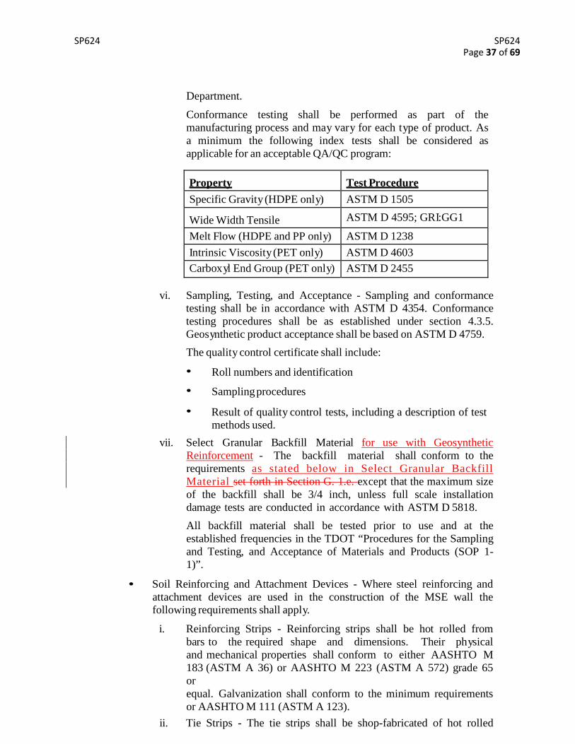
Conformance testing shall be performed as part of the manufacturing process and may vary for each type of product. As a minimum, the following index tests shall be considered as applicable for an acceptable QA/QC program:
Property Test Procedure Specific Gravity (HDPE only) ASTM D 1505 Wide Width Tensile ASTM D 4595; GRI:GG1 Melt Flow (HDPE and PP only) ASTM D 1238 Intrinsic Viscosity (PET only) ASTM D 4603 Carboxyl End Group (PET only) ASTM D 2455
vi. Sampling, Testing, and Acceptance - Sampling and conformance
testing shall be in accordance with ASTM D 4354. Conformance testing procedures shall be as established under 4.3.5. Geosynthetic product acceptance shall be based on ASTM D 4759.
The quality control certificate shall include:
• Roll numbers and identification • Sampling procedures • Result of quality control tests, including a description of
test methods used
vii. Select Granular Backfill Material for use with Geosynthetic Reinforcement – The backfill material shall conform to the requirements as s tated below in Select Granular Backfi l l Materialset forth in Section F.1.e. except that the maximum size of the backfill shall be 3/4 inch, unless full scale installation damage tests are conducted in accordance with ASTM D 5818.
• Joint Materials - Installed to the dimensions and thicknesses in accordance with the plans or approved shop drawings.
i. If required, provide flexible foam strips for filler for vertical joints between panels, and in horizontal joints where pads are used, where indicated on the plans.
ii. Provide in horizontal joints between panels preformed EPDM rubber pads conforming to ASTM D 2000 for 4AA, 812 rubbers, neoprene elastomeric pads having a Durometer Hardness of 55 ± 5, or high density polyethylene pads with a minimum density of 59 lb/ft3 in accordance with ASTM D 1505.
iii. Cover all joints between panels on the back side of the wall with a geotextile meeting the minimum requirements for filtration applications as specified by AASHTO M 288. The minimum width and lap shall be 12 inches. Adhesive used to attach the filter fabric to the back of the panels shall be approved by the wall supplier.
SP624 SP624
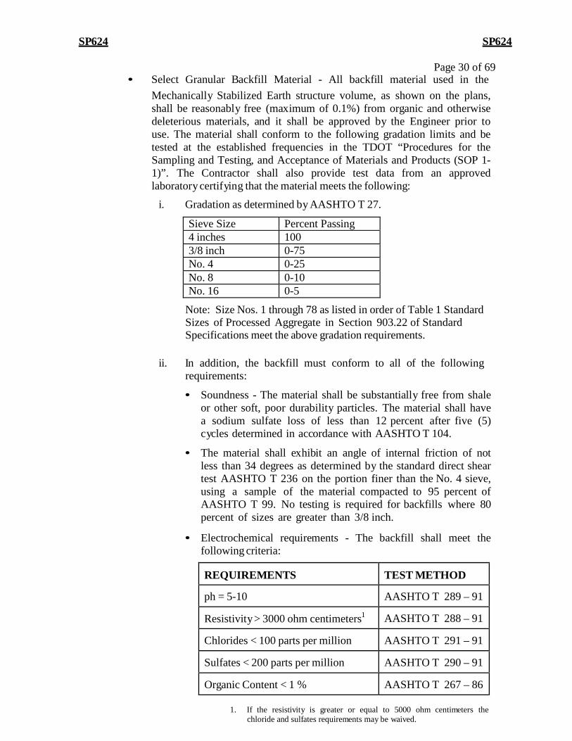
Page 30 of 69 • Select Granular Backfill Material - All backfill material used in the
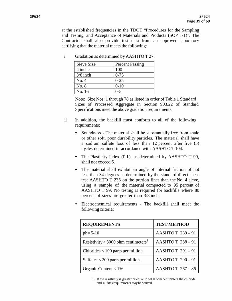
Mechanically Stabilized Earth structure volume, as shown on the plans, shall be reasonably free (maximum of 0.1%) from organic and otherwise deleterious materials, and it shall be approved by the Engineer prior to use. The material shall conform to the following gradation limits and be tested at the established frequencies in the TDOT “Procedures for the Sampling and Testing, and Acceptance of Materials and Products (SOP 1- 1)”. The Contractor shall also provide test data from an approved laboratory certifying that the material meets the following:
Note: Size Nos. 1 through 78 as listed in order of Table 1 Standard Sizes of Processed Aggregate in Section 903.22 of Standard Specifications meet the above gradation requirements.
ii. In addition, the backfill must conform to all of the following
requirements:
• Soundness - The material shall be substantially free from shale or other soft, poor durability particles. The material shall have a sodium sulfate loss of less than 12 percent after five (5) cycles determined in accordance with AASHTO T 104.
• The material shall exhibit an angle of internal friction of not less than 34 degrees as determined by the standard direct shear test AASHTO T 236 on the portion finer than the No. 4 sieve, using a sample of the material compacted to 95 percent of AASHTO T 99. No testing is required for backfills where 80 percent of sizes are greater than 3/8 inch.
• Electrochemical requirements - The backfill shall meet the following criteria:
REQUIREMENTS
TEST METHOD
ph = 5-10 AASHTO T 289 – 91
Resistivity > 3000 ohm centimeters1 AASHTO T 288 – 91
Chlorides < 100 parts per million AASHTO T 291 – 91
Sulfates < 200 parts per million AASHTO T 290 – 91
Organic Content < 1 % AASHTO T 267 – 86
1. If the resistivity is greater or equal to 5000 ohm centimeters the chloride and sulfates requirements may be waived.
SP624 SP624
Page 31 of 69
• Unit weight- The unit weight of the backfill mat eri al (at optimum condition) shall meet the requirements of the approved shop drawings or plans.
• Concrete Leveling Pad, Traffic Barrier and Coping - The concrete shall conform to the requirements of the Standard Specifications for Class A concrete.
• Acceptance of Material - The Contractor shall furnish the Engineer a Certificate of Compliance certifying the above materials comply with the applicable contract specifications. A copy of all test results performed by the Contractor necessary to assure contract compliance shall be furnished to the Engineer.
Acceptance will be based on the TDOT “Procedures for the Sampling and Testing, and Acceptance of Materials and Products (SOP 1-1)”.
2. Construction
a. Foundation Preparation - The foundation for the MSE wall shall be graded level for a minimum width equal to the width of the reinforced volume and leveling pad plus one (1) foot, or as shown on the plans, using the top of the leveling pad as the grade elevation. Prior to wall construction, the foundation shall be compacted to 95 percent of optimum density, as directed by the Engineer. Any foundation soils found to be unsuitable shall be removed as directed by the Engineer and replaced with select granular backfill material compacted to 95 percent of AASHTO T 99. The contractor shall conduct any ground improvements required by the contract plans as part of foundation preparation.
At each panel foundation level, a precast reinforced or a cast-in-place unreinforced concrete leveling pad of the type shown on the plans shall be provided. The concrete shall be Class “A” concrete with compressive strength of 3000 psi (28 day strength). The leveling pad shall be cured a minimum of 12 hours before placement of wall panels.
b. Wall Erection - Where a proprietary wall system is used, a field representative shall be available during the erection of the wall to assist the fabricator, Contractor, and Engineer. If there is more than one wall of the same type on the project, this requirement will apply to construction of the initial wall only. After construction of the initial wall, the representative will be available on an as-needed basis, as requested by the Engineer, during construction of the remainder of the walls. Wall erection shall be in conformance with the latest edition of the MSE wall construction manual as published by the wall supplier. For erection, panels are handled by means of a lifting device set into the upper edge of the panel. Precast concrete panels shall be placed such that a final vertical face will be obtained.
It shall be the responsibility of the Contractor to consult with the designer/supplier and to utilize the proper methods necessary to achieve a vertical face for the final wall. Panels should be placed in successive horizontal lifts as backfill placement proceeds. As backfill material is placed behind the panels, the panels shall be maintained in position by
SP624 SP624
Page 32 of 69 means of temporary wedges or bracing according to the wall supplier’s recommendations. External bracing shall also be required for this initial lift. The wedges shall remain in place until the fourth layer of panels is placed, at which time the bottom layer of wedges shall be removed. Each succeeding layer of wedges shall be removed as the succeeding panel layers are placed. When the wall is completed, all wedges shall be removed. No wedges shall be used as a means of leveling panels on leveling pads. Wedges placed below the ground line on the front face of the wall shall be removed before this area is backfilled.
Tolerances and alignment shall be as follows:
i. Horizontal and vertical joint openings between panels shall be uniform. The maximum allowable offset in any panel joint shall be 3/4 inch.
ii. Vertical tolerance (plumbness) and horizontal alignment tolerances as the wall is constructed shall not exceed 3/4 inch when measured along a 10 foot straightedge.
The overall vertical tolerance of the wall (plumbness from top to bottom)
SP624 SP624
in its final position shall not exceed 3/4 inch per 10 feet of wall height.
Cast-in-place concrete shall be placed on top of wall panels to allow precast coping elements on top of the wall to be brought to proper grade.
Prior to placing any select backfill material on any soil reinforcement device, all connections to the panels shall be completed.
c. Backfill Placement - Backfill placement shall closely follow the erection of each lift of panels. Backfill shall be placed in such a manner as to avoid any damage or disturbance to the wall materials including panels, soil reinforcements, and connections, or misalignment of the facing panels or reinforcing elements. Any wall materials which may become damaged or disturbed during backfill placement, or due to wall settlement prior to completion of the project shall be either removed and replaced at the Contractor’s expense or corrected, as directed by the Engineer. Any misalignment or distortion of the wall facing panels due to placement of backfill outside the limits of this section shall be corrected, as directed by the Engineer at the Contractor’s expense. Backfill placement methods near the facing shall assure that no voids exist directly beneath the reinforcing elements.
Backfill shall be compacted to 95 percent of the maximum density as determined by AASHTO T 99. When the backfill supports a spread footing of a bridge or other structural load, the top 5 feet shall be compacted to 100 percent of the maximum density. For backfills containing more than 30 percent retained on the ¾ inch sieve, a method compaction consisting of a minimum of 2 passes of a steel drum roller or truck equipment equivalent or larger than a Caterpillar D-6 Bulldozer shall be used.
The moisture content of the backfill material prior to and during compaction shall be uniformly distributed throughout each layer. Backfill materials shall be placed at a moisture content not more than 2 percentage points less than or equal to the optimum moisture content. Backfill material with a placement moisture content in excess of the optimum moisture content shall be removed and reworked until the moisture content is uniformly acceptable throughout the entire lift. The optimum moisture content shall be determined in accordance with AASHTO T 99.
At each soil reinforcement device level, backfill shall be compacted to the full length of reinforcement devices and be sloped to drain away from the wall before placing and attaching the next layer of reinforcement devices. The compacted backfill shall be level with the connecting device before the reinforcement device can be connected. Compaction within three feet of the back face of the wall facing panel shall be achieved with at least three (3) passes of a light weight mechanical tamper, roller, or vibratory system.
Unless otherwise indicated on the plans or directed by the Engineer, soil reinforcement devices shall be placed at 90 degrees to the face of the wall. The maximum lift thickness before compaction shall be ten (10) inches and shall closely follow panel erection. The Contractor shall decrease this
SP624 SP624
Page 33 of 69
lift thickness, if required, to obtain the specified density.
At the end of each day’s operation, the Contractor shall slope the last level of backfill away from the wall facing to rapidly direct runoff or rainwater away from the wall face. In addition, the Contractor shall not allow surface runoff from adjacent areas to enter the wall construction site.
G. Prefabricated Modular Block Facing Mechanically Stabilized Earth (MSE) Wall (See QPL 38 for Approved Manufacturer/Supplier)
1. Materials
General - The contractor shall make arrangements to purchase or manufacture the facing elements, reinforcing mesh or strips, attachment devices, joint filler, and all other necessary components. Materials not conforming to this section or from sources not listed in the contract document shall not be used without written consent from the Engineer.
• Concrete Modular Block Facing - The concrete modular blocks shall be either hollow or solid concrete structural retaining wall units, machine made from Portland cement, water, and mineral aggregates with or without the inclusion of other materials. The units are intended for use in the construction of mortarless, modular block retaining (MBW) walls.
i. Cementious Materials - Materials shall conform to the following:
• Portland Cement - AASHTO M 85 (ASTM C 150).
• Blended Cements – Type IP -AASHTO M 240 (ASTM C 595).
• Pozzolans – Class C or Class F fly ash -AASHTO M 295 Blast Furnace Slag Cement – grade 100 or 120- AASHTO M 302 (ASTM C 989).
ii. Aggregates - Aggregates shall conform to the following specifications, except that grading requirements shall not necessarily apply:
• Normal Weight Aggregates – TDOT Standard Specification sections 903.01 and 903.03.
• Lightweight Aggregates - TDOT Standard Specification section 903.19.
iii. Other Constituents - Air-entraining agents, coloring pigments, integral water repellants, finely ground silica, and other constituents shall be previously established as suitable for use in concrete MBW units and shall conform to applicable AASHTO Standards or, shall be shown by test or experience to be not detrimental to the durability of MBW units or any material customarily used in masonry construction.
iv. Physical Requirements. Prior to delivery to the work site, the units shall conform to the following physical requirements:
(Individual coupon) 3. Maximum water absorption = 5% 4. Maximum number of blocks per lot = 2,000
Also, prior to delivery, TDOT will conduct verification testing on the modular blocks in accordance with the TDOT “Procedures for the Sampling and Testing, and Acceptance of Materials and Products (SOP 1-1)
If products are manufactured out of state, TDOT may verify at the project site PRIOR to the placement of the units. The Contractor, or producer, shall notify the Regional Materials and Tests Division that products need to be verified.
v. Tolerances. Blocks shall be manufactured within the following tolerances:
• The length and width of each individual block shall be within 1/8 inch of the specified dimension. Hollow units shall have a minimum wall thickness of 1-1/4 inch.
• The height of each individual block shall be within 1/16 inch of the specified dimension.
• When a broken face finish is required, the dimension of the front face shall be within 1 inch of the theoretical dimension of the unit.
• Finish and Appearance. All units shall be sound and free of cracks or other defects that would interfere with the proper placing of the unit or significantly impair the strength or permanence of the construction. Minor cracks (e.g. no greater than 1/32 inch in width and no longer than 25 % of the unit height) incidental to the usual method of manufacture or minor chipping resulting from shipment and delivery, are not grounds for rejection.
The face or faces of units that are to be exposed shall be free of chips, cracks or other imperfections when viewed from a distance of 30 feet under diffused lighting. Up to five (5) percent of a shipment may contain slight cracks or small chips not larger than 1 inch.
Color and finish shall be as shown on the plans and shall be erected with a running bond configuration.
• If pins are required to align MBW units, they shall consist of a non-degrading, polymer or galvanized steel and be made for the express use with the MBW units supplied.
• Cap units shall be cast to or attached to the top MBW units in strict accordance with the manufacturer’s requirements and the adhesive manufacturer’s recommended procedures. The Contractor shall provide a written 10 year warranty acceptable to the Department that the integrity of the materials used to
SP624 SP624 Page 35 of 69
attach the cap blocks will preclude separation and displacement of the cap blocks for the warranty period.
vi. Sampling and Testing. Acceptance of the concrete block with respect to compressive strength and absorption will be determined on a lot basis. The lot will be randomly sampled in accordance with ASTM C 140. Compressive strength and absorption tests shall be performed by the manufacturer and submitted to the Department. Compressive strength test specimens shall be cored or shall conform to the saw-cut coupon provisions of section 6.2.4 of ASTM C 140. Blocks represented by test coupons that do not reach an average compressive strength of 4,000 psi or an individual strength of 3500 psi, or have less than 5 % absorption will be rejected.
vii. Rejection. Blocks shall be rejected because of failure to meet any of the requirements specified above. In addition, any or all of the following defects shall be sufficient cause for rejection.
• Defects that indicate imperfect molding.
• Defects indicating honeycomb or open texture concrete.
• Cracked or severely chipped blocks. • Color variation on front face of block due to excess form oil or
other reasons.
Blocks may also be rejected if TDOT verification test results do not comply with the requirements specified above.
• Unit Fill - The unit fill and drainage aggregate shall be a well graded crushed stone or granular fill meeting the following gradation:
U.S. Sieve Size
Percent Passing
1 inch 100-75
3/4 inch 50-75
No. 4 0-60
No. 40 0-50
No. 200 0-5
• Geosynthetic Reinforcement Material - The following requirements shall apply for geosynthetic reinforcement material:
i. Geotextiles and Thread for Sewing - Woven or nonwoven geotextiles shall consist only of long chain polymeric filaments or yarns formed into a stable network such that the filaments or yarns retain their position relative to each other during handling, placement, and design service life. At least 95 percent by weight of the long chain polymer shall be polyolefin or polyester. The material shall be free of defects and tears. The
SP624 SP624 Page 36 of 69
geotextile shall conform as a minimum to the properties indicated for Separation, Medium Survivability indicated under AASHTO T 288. The geotextile shall be free from any treatment or coating that might adversely alter its physical properties after installation.
ii. Geogrids - The geogrid shall be a regular network of integrally connected polymer tensile elements with aperture geometry sufficient to permit significant mechanical interlock with the surrounding soil or rock. The geogrid structure shall be dimensionally stable and able to retain its geometry under manufacture, transport and installation.
iii. Required Properties - The specific geosynthetic material(s) shall be pre-approved by the Department and shall have certified long-term strength (Tal) as determined by:
• Long-Term strength (Tal) based on Tal = Tult/(RFD)*(RFID)*(RFCR) where RFCR is developed from creep tests performed in accordance with ASTM D 5262, RFID obtained from site installation damage testing and RFID
from hydrolysis or oxidative degradation testing extrapolated to 75 or 100 year design life.
• Ultimate Strength (TULT) based upon minimum average roll
values (MARV) (lb/ft), ASTM D4595.
• Pullout Resistance Factor developed in accordance with chapter 3 of FHWA-SA-96-071.
iv. Certification - The Contractor shall submit a manufacturer’s certification that the geosynthetics supplied meet the respective index criteria set when the geosynthetic was approved by the Department, measured in full accordance with all test methods and standards specified and as set forth in this section of the TDOT Earth Retaining Structures Manual. The manufacturer’s certificate shall state that the furnished geosynthetic meets the requirements of this document as evaluated by the manufacturer’s quality control program. The certificates shall be attested to by a person having legal authority to bond the manufacturer. In case of dispute over validity of values, the Engineer can require the Contractor to supply test data from a Department approved laboratory to support the certified values submitted.
v. Manufacturing Quality Control: The geosynthetic reinforcement shall be manufactured with a high degree of quality control. The manufacturer is responsible for establishing and maintaining a quality control program to ensure compliance with the requirements of the TDOT Earth Retaining Structures Manual. The purpose of the QC testing program is to verify that the geosynthetic being supplied to the project is representative of the material used for performance testing and approval by the
SP624 SP624 Page 37 of 69
Department.
Conformance testing shall be performed as part of the manufacturing process and may vary for each type of product. As a minimum the following index tests shall be considered as applicable for an acceptable QA/QC program:
Property
Test Procedure Specific Gravity (HDPE only) ASTM D 1505
Wide Width Tensile ASTM D 4595; GRI:GG1
Melt Flow (HDPE and PP only) ASTM D 1238 Intrinsic Viscosity (PET only) ASTM D 4603 Carboxyl End Group (PET only) ASTM D 2455
vi. Sampling, Testing, and Acceptance - Sampling and conformance testing shall be in accordance with ASTM D 4354. Conformance testing procedures shall be as established under section 4.3.5. Geosynthetic product acceptance shall be based on ASTM D 4759.
The quality control certificate shall include:
• Roll numbers and identification
• Sampling procedures
• Result of quality control tests, including a description of test methods used.
vii. Select Granular Backfill Material for use with Geosynthetic Reinforcement - The backfill material shall conform to the requirements as stated below in Select Granular Backfill Material set forth in Section G. 1.e. except that the maximum size of the backfill shall be 3/4 inch, unless full scale installation damage tests are conducted in accordance with ASTM D 5818.
All backfill material shall be tested prior to use and at the established frequencies in the TDOT “Procedures for the Sampling and Testing, and Acceptance of Materials and Products (SOP 1- 1)”.
• Soil Reinforcing and Attachment Devices - Where steel reinforcing and attachment devices are used in the construction of the MSE wall the following requirements shall apply.
i. Reinforcing Strips - Reinforcing strips shall be hot rolled from bars to the required shape and dimensions. Their physical and mechanical properties shall conform to either AASHTO M 183 (ASTM A 36) or AASHTO M 223 (ASTM A 572) grade 65 or equal. Galvanization shall conform to the minimum requirements or AASHTO M 111 (ASTM A 123).
ii. Tie Strips - The tie strips shall be shop-fabricated of hot rolled
SP624 SP624 Page 38 of 69
steel conforming to the minimum requirements of ASTM A 570, Grade 50 or equivalent. Galvanization shall conform to AASHTO M111. Tie straps may be partially bent before shipment to the precast yard. Minimum bending radius shall be one inch. Final bending may be accomplished at the precast yard.
iii. Reinforcing Mesh - Reinforcing mesh shall be shop fabricated of cold drawn steel wire conforming to the minimum requirements of AASHTO M 32 (ASTM A 82) and shall be welded into the finished mesh fabric in accordance with AASHTO M 55 (ASTM A 185). Galvanization shall be applied after the mesh is fabricated and conform to the minimum requirements of AASHTO M 111
iv. Fasteners - Fasteners shall be high strength hexagonal cap screw bolts and nuts conforming to AASHTO M 164 (ASTM A 325).Galvanizing fastener elements, including washers, shall be in accordance with AASHTO M 232 (ASTM A 153). Bolts and nuts nominal diameter will be shown in the plans and supplied in accordance with the fasteners as specified previously.
v. Steel Strap Connections - The steel strap connection bar and plate shall meet the same requirements as the reinforcing and tie strips specified above. Bolts, nuts, and washers shall conform to the requirements for the fasteners specified above. Coatings for connecting devices shall be as specified below.
vi. Clevis Loop and Mesh Loop - Clevis loops and mesh loops shall be fabricated of cold drawn steel wire conforming to the requirements of AASHTO M 32 and welded in accordance with AASHTO M 55 and shall develop a minimum stress of 0.9 Fy.
vii. Connector Bar - Connector bar shall be fabricated of cold drawn steel wire conforming to the requirements of AASHTO M 32.
Holes for bolts shall be punched in the location shown. Surfaces resulting from punching holes for bolts shall be galvanized in accordance with AASHTO M 111. Those parts of the connecting devices which are threaded shall be galvanized in accordance with AASHTO M 232. Alignment pins are to be hot dip galvanized.
All connecting devices shall be to the dimensions shown on the plans. Connecting members and soil reinforcement devices shall be assembled prior to galvanization. All connecting devices shall be true to size and free from defects that may impair their strength or durability.
Any damage sustained by any part of the connecting devices, bolts or reinforcing devices during any phase of fabrication, storage or erection shall be repaired to the satisfaction of the Engineer at no increase in contract cost.
Select Granular Backfill Material - All backfill material used in the Mechanically Stabilized Earth structure volume, as shown on the plans, shall be reasonably free (maximum of 0.1%) from organic and otherwise deleterious materials, and it shall be approved by the Engineer prior to use. The material shall conform to the following gradation limits and be tested
SP624 SP624 Page 39 of 69
at the established frequencies in the TDOT “Procedures for the Sampling and Testing, and Acceptance of Materials and Products (SOP 1-1)”. The Contractor shall also provide test data from an approved laboratory certifying that the material meets the following:
Note: Size Nos. 1 through 78 as listed in order of Table 1 Standard Sizes of Processed Aggregate in Section 903.22 of Standard Specifications meet the above gradation requirements.
ii. In addition, the backfill must conform to all of the following
requirements:
• Soundness - The material shall be substantially free from shale or other soft, poor durability particles. The material shall have a sodium sulfate loss of less than 12 percent after five (5) cycles determined in accordance with AASHTO T 104.
• The Plasticity Index (P.I.), as determined by AASHTO T 90, shall not exceed 6.
• The material shall exhibit an angle of internal friction of not less than 34 degrees as determined by the standard direct shear test AASHTO T 236 on the portion finer than the No. 4 sieve, using a sample of the material compacted to 95 percent of AASHTO T 99. No testing is required for backfills where 80 percent of sizes are greater than 3/8 inch.
• Electrochemical requirements - The backfill shall meet the
following criteria:
REQUIREMENTS
TEST METHOD
ph= 5-10 AASHTO T 289 – 91
Resistivity > 3000 ohm centimeters1 AASHTO T 288 – 91
Chlorides < 100 parts per million AASHTO T 291 – 91
Sulfates < 200 parts per million AASHTO T 290 – 91
Organic Content < 1% AASHTO T 267 – 86
1. If the resistivity is greater or equal to 5000 ohm centimeters the chloride and sulfates requirements may be waived.
SP624 SP624 Page 40 of 69
• Unit weight- The unit weight of the backfill material (at
optimum condition) shall meet the requirements of the approved shop drawings or plans.
• Concrete Leveling Pad, Traffic Barrier and Coping - The concrete shall conform to the requirements of the Standard Specifications for Class A concrete.
• Acceptance of Material - The contractor shall furnish the Engineer a Certificate of Compliance certifying the above materials comply with the applicable contract specifications. A copy of all test results performed by the Contractor necessary to assure contract compliance shall be furnished to the Engineer.
2. Construction
a. Wall Excavation - Unclassified excavation shall be in accordance with the requirements of the Standard Specifications and in reasonably close conformity with the limits and construction lines shown on the plans. Temporary excavation support as required shall be the responsibility of the Contractor.
b. Foundation Preparation - The foundation for the MSE wall shall be graded level for a minimum width equal to the width of the reinforced volume and leveling pad plus one (1) foot, or as shown on the plans, using the top of the leveling pad as the grade elevation. Prior to wall construction, the foundation shall be compacted to 95 percent of optimum density, as directed by the Engineer. Any foundation soils found to be unsuitable shall be removed as directed by the Engineer and replaced with select granular backfill material compacted to 95 percent of AASHTO T 99 methods. The contractor shall conduct any ground improvement required by the contract plans as part of foundation preparation.
At each block foundation level, a precast reinforced or a cast-in-place unreinforced concrete leveling pad of the type shown on the plans shall be provided. The concrete shall be Class A concrete with compressive strength of 3000 psi (28 day strength). The leveling pad shall be cured a minimum of 12 hours before placement of wall panels.
c. Wall Erection - Where a proprietary wall system is used, a field representative shall be available during the erection of the wall to assist the fabricator, Contractor, and Engineer. If there is more than one wall of the same type on the project, this requirement will apply to construction of the initial wall only. After the initial wall, the representative will be available on an as-needed basis, as requested by the Engineer, during construction of the remainder of the walls. Wall erection shall be in conformance with the latest edition of the MSE wall construction manual as published by the wall supplier.
It shall be the responsibility of the Contractor to consult with the designer/supplier and to utilize the proper methods necessary to achieve a vertical face for the final wall. Blocks should be placed in successive horizontal lifts as backfill placement proceeds per the manufacturer’s recommendations.
SP624 SP624 Page 41 of 69
Cast-in-place concrete shall be placed on top of wall panels to allow precast coping elements on top of the wall to be brought to proper grade.
Prior to placing any select backfill material on any soil reinforcement device, all connections to the blocks shall be completed.
d. Backfill Placement - Backfill placement shall closely follow the erection of each lift of blocks. Backfill shall be placed in such a manner as to avoid any damage or disturbance to the wall materials including blocks, soil reinforcements, and connections, or misalignment of the facing blocks or reinforcing elements. Any wall materials which may become damaged or disturbed during backfill placement, or due to wall settlement prior to completion of the project shall be either removed and replaced at the Contractor’s expense or corrected, as directed by the Engineer. Any misalignment or distortion of the wall facing blocks due to placement of backfill outside the limits of this section shall be corrected, as directed by the Engineer. Backfill placement methods near the facing shall assure that no voids exist directly beneath the reinforcing elements.
Backfill shall be compacted to 95 percent of the maximum density as determined by AASHTO T 99. When the backfill supports a spread footing of a bridge or other structural load, the top 5 feet shall be compacted to 100 percent of the maximum density. For backfills containing more than 30 percent retained on the ¾ inch sieve, a method compaction consisting of a minimum of 2 passes of a steel drum roller or tracked equipment equivalent or larger than a Caterpillar D-6 Dozer shall be used.
The moisture content of the backfill material prior to and during compaction shall be uniformly distributed throughout each layer. Backfill materials shall have a placement moisture content less than or equal to the optimum moisture content. Backfill material with placement moisture content in excess of the optimum moisture content shall be removed and reworked until the moisture content is uniformly acceptable throughout the entire lift. The optimum moisture content shall be determined in accordance with AASHTO T 99.
At each soil reinforcement device level, backfill shall be compacted to the full length of reinforcement devices and be sloped to drain away from the wall before placing and attaching the next layer of reinforcement devices. The compacted backfill shall be level with the connecting device before the reinforcement device can be connected. Compaction within three feet of the back of the wall facing shall be achieved with at least three (3) passes of a light weight mechanical tamper, roller, or vibratory system.
Unless otherwise indicated on the plans or directed by the Engineer, soil reinforcement devices shall be placed at 90 degrees to the face of the wall. The maximum lift thickness before compaction shall be ten (10) inches and shall closely follow modular block erection. The Contractor shall decrease this lift thickness, if required, to obtain the specified density.
At the end of each day’s operation, the Contractor shall slope the last level
SP624 SP624 Page 42 of 69
of backfill away from the wall facing to rapidly direct runoff or rainwater away from the wall face. In addition, the contractor shall not allow surface runoff from adjacent areas to enter the wall construction site.
H. Anchored Wall (See QPL 38 for Approved Manufacturer/Supplier)
Part A - Part A covers specifications for permanent ground anchor walls exclusive of the ground anchors.
1. Design Criteria
Unless otherwise directed the Contractor shall select the type of wall element to be used. The wall shall be designed for shear, moment, and lateral and axial capacity in accordance with AASHTO LRFD procedures. The Contractor shall be responsible for determining the length of the wall element and required section necessary to resist loadings due to earth, and water forces while controlling ground movements. Structure design life and corrosion protection requirements for sheet-piles and soldier beams will be provided on the contract drawings. Soil properties, safety factors, anchor tendon corrosion protection requirements, wall finish and color requirements, and appurtenance locations are given in the contract plans or specifications.
The Contractor shall be familiar with the requirements for ground anchors described in Part B, “Ground Anchors”. The contractor shall incorporate all dimensional and location restrictions on ground anchor locations, spacing, and length of anchor bond length and unbonded length that may affect the design of the wall system covered by this section.
• The wall system shall be designed to resist maximum anticipated loadings calculated for the effects of any special loadings shown on the contract plans.
• The wall shall be designed to ensure stability against passive failure of the embedded portion of the vertical wall elements (below the base of excavation).
• The axial load carrying capacity of the embedded portion of the vertical wall elements (below the base of the excavation) shall be evaluated.. The wall shall be designed to resist vertical loads including vertical anchor forces and the weight of the lagging and the vertical wall elements. Relying on transfer of vertical load into the soil behind the wall by friction shall not be permitted, unless approved by the Engineer.
• Permanent facing shall be precast or cast-in-place reinforced concrete. Architectural facing treatments, if required, shall be as indicated on the contract drawings. The facing shall extend a minimum of 2.0ft below the gutter line or, if applicable, the ground line adjacent to the wall unless otherwise indicated on the contract drawings.
• The Contract Plans will provide minimum requirements of design elements in order to provide global stability requirement such as minimum embedment of vertical pile elements or minimum lengths of unbonded (free-length) zone for anchors. The wall design shall provide these minimum requirements.
• Wall Drainage. The wall drainage system shall operate by gravity and
SP624 SP624 Page 43 of 69
shall be capable of relieving water pressures on the back face of the wall under anticipated worst case water pressure conditions. When drainage systems are incorporated into the specific design, hydrostatic head on the back of the wall shall not exceed 6 inches above the elevation of the drainage collection pipe.
2. Materials
The Contractor shall not deliver materials to the site until the Engineer has approved the submittals outlined in section 3.0. The Contractor shall protect the materials from the elements by appropriate means. Prestressing steel strands and bars shall be stored and handled in accordance with the manufacturer's recommendations and in such a manner that no damage to the component parts occurs. All steel components shall be stored under cover and protected against moisture.
• Soldier Beam and Structural Steels
i. Steel Soldier Beams - Steel soldier beams shall be of the type and weight indicated on the approved working drawings. Steel soldier beams shall conform to the requirements of AASHTO M 183 (ASTM A 36) or AASHTO M 223 (ASTM A 572) unless otherwise specified.
ii. Steel Sheet Piles - Steel sheet piles shall be of the type and weight indicated on the approved working drawings. Steel sheet piles shall conform to the requirements of AASHTO M 202 (ASTM A 328) or AASHTO M 270 (ASTM A 709) Grade 50.
iii. Steel Plate - Steel used to fabricate steel studs and other devices shall conform to the requirements of AASHTO M 169 (ASTM A 108)
iv. Steel Tube - Steel tube shall conform to the requirements of ASTM A 500.
v. Reinforcing Steel - Reinforcing steel shall conform to ASTM A 615. The required Grade of all reinforcing shall be shown on the plans.
• Concrete
i. Cement - Portland cement shall be Type I or II and shall conform to AASHTO M 85.
ii. Structural Concrete - Structural concrete shall conform to the requirements of Section 604 of the TDOT Standard Specifications Structural concrete shall be Class A with a minimum 28-day compressive strength of 3000 psi, unless otherwise noted on the contract drawings.
iii. Lean-Mix Concrete Backfill - Lean-mix concrete backfill shall consist of Type I or Type II Portland cement, fine aggregate and water. Each cubic yard of lean-mix concrete backfill shall consist of a minimum of one sack (94lbs) of Portland cement.
SP624 SP624 Page 44 of 69
iv. Precast Concrete - Precast concrete elements such as panels shall
be made by an approved plant in accordance with the TDOT Procedure for the “Manufacture and Acceptance of Pre-cast Concrete Drainage Structures, Noise Wall panels, and Retaining wall panels”.
Out-of-state producers shall provide documentation of material quality before the manufacture of any pre-cast products (i.e. aggregate quality reports, cement/steel mill test reports, etc.)
Unless otherwise shown on the contract drawings, Portland cement concrete used in precast elements shall conform to Class D with a minimum 28-day compressive strength of 4000 psi
• Drainage Materials
i. Drainage Aggregate - Drainage aggregate to be used as a drainage medium shall conform to section 903.17 of the Standard Specifications.
ii. Preformed Permeable Geocomposite Drains – The preformed permeable geocomposite drains shall be continuous and a minimum of one (1) foot wide. The drains shall be placed in sections with a minimum overlap of one (1) foot and be spliced to assure continuous drainage.
iii. Pipe and Perforated Pipe - Pipe and perforated pipe shall conform to section 610 of the Standard Specifications.
• Lagging
i. Temporary Timber Lagging - Temporary timber lagging shall be construction grade rough cut and shall be a minimum of 3 inches thick. Where necessary, the Contractor shall provide certification that the timber conforms to the grade, species, and other specified requirements. If the timber is to be treated with a preservative, a certificate of compliance shall be furnished.
ii. Permanent Timber Lagging – Permanent timber lagging shall conform to all requirements of section 2.d.i. and shall be constructed from structural stress-graded lumber.
3. Construction
• General Considerations
i. Wall elements for anchored walls designed and constructed in accordance with this manual shall be either continuous interlocking sheet-piles or steel soldier beams that are either driven or placed in pre-drilled holes that are subsequently backfilled with lean mix or structural concrete.
• Excavation
i. Excavation below a level of anchors shall be limited to 2 feet below the anchor level and shall not commence below this level until anchors at that level have been installed, load tested, locked
SP624 SP624 Page 45 of 69
off and accepted by the Department. Placement of timber lagging shall immediately follow excavation in the front of the wall.
• Driven Sheet Pile and Soldier Beam Installation.
i. Driven sheet piles and soldier beams shall be driven to the specified minimum tip elevation shown on the approved working drawings. The Contractor shall select a sheet pile or soldier beam section that satisfies all design criteria. The Contractor shall select a driving method and pile driving and ancillary equipment consistent with the expected ground conditions at the site. The sheet-pile or soldier beam shall be driven to the specified minimum tip elevation or to the approved elevation based on bearing capacity without damaging the sheet pile or soldier beam. The interlocks between adjacent sheet piles shall not be damaged. Equipment shall be used to permit the impact energy to be distributed over the tops of the sheet pile or soldier beam.
• Soldier Beam Installation in Pre-drilled Holes
i. Excavations required for soldier beam placement shall be performed to the dimensions and elevations on the approved working drawings. The methods and equipment used shall be selected by the Contractor.
ii. The Contractor shall ensure that the sidewalls of the pre-drilled holes (i.e. shafts) do not collapse during drilling. Uncased shafts may be used where the sides and the bottom of the shaft are stable and may be visually inspected prior to placing the soldier beam and concrete. Casing or drilling muds shall be used where the sides of the shaft require additional support.
iii. The Contractor shall provide equipment for checking the dimensions and alignment of each shaft excavation. The dimensions and alignment shall be determined by the Contractor but shall be observed by the Inspector. The Inspector will check the alignment of the drilling equipment at the beginning of shaft construction and periodically thereafter. Final shaft depth shall be measured after final cleaning by the Contractor.
iv. Loose material shall be removed from the bottom of the shaft. No more than 2 feet of standing water shall be left in the bottom of the shaft prior to beginning soldier beam installation.
v. The soldier beam shall be placed in the shaft without difficulty and aligned prior to general placement of concrete. The Contractor may place up to 2 feet of concrete at the bottom of the shaft to assist in aligning the soldier beam. The soldier beam shall be blocked or clamped in place at the ground surface, prior to placement of concrete.
vi. For shafts constructed without casing or drilling muds, concrete (either structural or lean-mix backfill) may be placed by free- falling the concrete from the ground surface down the shaft and
SP624 SP624
Page 46 of 69 around the soldier beam. If casing is used, the placement of concrete shall begin prior to casing removal. Remove the casing while the concrete remains workable. For shafts constructed using slurry, concrete shall be placed using the tremie method from the bottom of the shaft. The tremie pipe shall be withdrawn slowly as the level of the concrete rises in the shaft and the level of the tremie pipe outlet shall never exceed the height of the slurry.
• Wall Tolerances
i. Soldier beams shall be placed at the locations shown on the approved working drawings and shall not deviate by more than 1 foot along the horizontal alignment of the wall. The wall shall not deviate from the vertical alignment shown of the contract drawings by more than 4 inches in each plane.
ii. The soldier beam or sheet pile tip shall be installed to within 1 foot of the specified tip elevation shown on the approved working drawings.
iii. Whenever a soldier beam deviates in location or plumbness by more than the tolerance given in these guidelines, the Contractor, at his option, may provide corrective measures such as 1) rebuilding soldier beams; 2) redesigning soldier beam; 3) adjust soldier beam spacing by adding additional soldier beams; 4) redesigning concrete facing; 5) building up the soldier beam section, or 6) other methods.
• Welding and Splicing i. Splicing of sheet piles or soldier beams shall not be permitted,
unless approved by the Department. All structural welding of steel and steel reinforcement shall be performed by certified welders qualified to perform the type of welding shown on the shop drawings. All sheet piles or soldier beams shall be cutoff to a true plane at the elevations shown on the approved working drawings. All cutoff lengths shall remain the property of the Contractor and shall be properly disposed.
• Timber Lagging Installation
i. Timber lagging shall be placed from the top-down in sufficiently small lifts immediately after excavation to prevent erosion of materials into the excavation. Prior to lagging placement, the soil face shall be smoothed to create a contact surface for the lagging. Large gaps behind the lagging shall be backfilled and compacted prior to applying any loads to the ground anchors.
ii. A gap shall be maintained between each vertically adjacent lagging board for drainage between adjacent lagging sections. In no case shall lagging be placed in tight contact to adjacent lagging.
• Drainage System Installation i. The Contractor shall handle preformed permeable geocomposite
drains in such a manner as to ensure the geocomposite drain is not
SP624 SP624
Page 47 of 69 damaged in any way. Care shall be taken during placement of the geocomposite drain not to entrap dirt or excessive dust in the geocomposite drain that could cause clogging of the drainage system. Delivery, storage, and handling of the geocomposite drains shall be as provided in the plans or based on manufacturer’s recommendations.
ii. Drainage geocomposite strips shall be placed and secured tightly against the timber lagging with the fabric facing the lagging. A continuous sheet of drainage geocomposite that spans between adjacent soldier beams shall not be allowed. Seams and overlaps between adjacent composites shall be made according to the special provisions or manufacturer’s recommendations and specifications. Repairs shall be performed at no additional cost to the Department and shall conform to the plans or manufacturer’s recommendation.
iii. Where drainage aggregate is used to construct a vertical drain behind the permanent wall and in front of the lagging, the drainage aggregate shall be placed in horizontal lifts. The construction of the vertical drain should closely follow the construction of the precast facing elements. Care should be exercised to ensure that connection devices between wall elements and facing elements are not damaged during the placement of the drainage aggregate.
iv. Perforated collector pipe shall be placed within the permeable material to the flow line elevations and at the location shown on the approved working drawings. Outlet pipes shall be placed at the low end of the collector pipe and at other locations shown or specified in the approved working drawings.
• Concrete Facing Installation
For permanent cast-in-place and precast concrete facings, concrete manufacture, handling, placement, and finishing shall conform to the requirements in Section 8 “Concrete Structures” of the AASHTO - LRFD Bridge Construction Sp e c i f i c a t i on s w i t h i n t e r im s . Connections used to secure the facing to wall elements shall conform to the details shown on the approved working drawings. The exposed surface of the concrete facing shall receive a Class I finish as specified in Section 8 “Concrete Structures,” unless a special architectural treatment is specified.
Part B, Anchored Wall (See QPL 38 for Approved Manufacturer/Supplier) – Part B covers specifications for the design, construction and testing of Permanent Ground Anchors.
1. Description
The work covered under this section includes the furnishing of all materials, labor, tools, equipment, and other incidental items for the designing, detailing, and construction of permanent ground anchors. All other items included in the construction of the permanent ground anchors not specifically mentioned herein shall
SP624 SP624
Page 48 of 69 conform to all applicable sections of the Tennessee Department of Transportation Standard Specifications for Road and Bridge Construction, henceforth referred to as the Standard Specifications, the current AASHTO LRFD Bridge Design Specifications with latest revisions, the current AASHTO LRFD Bridge Construction Specifications with interims, and the latest version of Post Tensioning Institute (PTI) Standards, including: 1. PTI, “Post Tensioning Manual”, 2. PTI “Specification for Unbonded Single Strand Tendons”, 3. PTI “Recommendations for Prestressed Rock and Soil Anchors.”
Unless otherwise noted the Contractor shall select the ground anchor type, drilling method, grouting method, and grout pressures, determine the ground anchor capacity, bond length, free stressing (unbonded) length, and anchor diameter. The Contractor shall be responsible for installing ground anchors that will develop the load-carrying capacity indicated on the approved working drawings in accordance with the testing subsection of this section. The anchor tendon shall be protected from corrosion as shown on the approved working drawings and in accordance with the requirements of this specification.
2. Design Criteria
• Unless otherwise directed the Contractor shall select the type of tendon to be
used. The tendon shall be sized so the design load does not exceed 60 percent of the specified minimum tensile strength of the prestressing steel. The lock- off load for the tendon shall be chosen based on anticipated time or activity dependent load changes, but shall not exceed 70 percent of the specified minimum tensile stress of the prestressing steel. The prestressing steel shall be sized so the maximum test load does not exceed 80 percent of the specified minimum tensile strength of the prestressing steel.
• The Contractor shall be responsible for determining the bond length necessary
to develop the design load indicated on the approved working drawings. The minimum bond length shall be 15 feet for strand tendons in rock and 10 feet for bar tendons in rock. The minimum bond length shall be 15 feet for strand and bar tendons in soil. The minimum tendon bond length shall be 10 feet.
• The free stressing length (unbonded length) for rock and soil anchors shall not
be less than 10 feet for bar tendons and 15 feet for strand tendons. The free stressing length shall extend at least 5 feet or 20 percent of the height of the wall, whichever is greater, behind the critical failure surface. The critical failure surface shall be evaluated using slope stability or similar procedures.
3. Submittals
Requirements for submittals are as outlined above and also include the following:
• Contractor qualifications as outlined in Part A, of these anchored wall design
and construction requirements. • The working drawings and design submission shall include the following:
a) A ground anchor schedule giving: • Ground anchor number
SP624 SP624
Page 49 of 69 • Ground anchor design load • Type and size of tendon • Minimum total anchor length • Minimum bond length • Minimum tendon bond length
b)
• A
Minimum unbonded length drawing of the ground anchor tendon and the corrosion
protection system including details for the following:
• Spacers and their location • Centralizers and their location • Unbonded length corrosion protection system • Bond length corrosion protection system • Anchorage and trumpet • Anchorage corrosion protection system
• Certificates of Compliance for the following materials , if used. The certificate
shall state that the materials or assemblies to be provided will fully comply with the requirements of the contract.
a) Prestressing steel, strand or bar b) Portland cement c) Prestressing hardware d) Bearing plates e) Corrosion protection system
• The Contractor shall submit to the Engineer for review and approval or
rejection mill test reports for the prestressing steel and the bearing plate steel. The Engineer may require the Contractor to provide samples of any ground anchor material intended for use on the project. The prestressing steel and bearing plates shall not be incorporated in the work without the Engineer’s approval.
• The Contractor shall submit to the Engineer for review and approval or
rejection calibration data for each test jack, load cell, primary pressure gauge and reference pressure gauge to be used. Testing cannot commence until the Engineer has approved these calibrations.
• The Contractor shall submit to the Engineer within twenty calendar days after
the completion of the ground anchor work a report containing the following: a) Prestressing steel manufacturer’s mill test reports for the tendons
incorporated in the installation b) Grouting records indicating the cement type, quantity injected and
the grout pressures c) Ground anchor test results d) As-built drawings showing the location and orientation of each
ground anchor, anchor capacity, tendon type, total anchor length, bond length, unbonded length, and tendon bond length as installed
SP624 SP624
Page 50 of 69 and locations of all instruments installed by the Department.
• Existing Conditions – Prior to beginning work, the Department shall provide utility location plans to the Contractor. The Contractor is responsible for contacting a utility location service to verify the location of underground utilities before starting work. The Contractor shall survey the condition of adjoining properties and make records and photographs of any evidence of settlement or cracking of any adjacent structures. The Contractor’s report of this survey shall be delivered to the Department before work begins.
4. Materials
• General
a) The Contractor shall not deliver materials to the site until the
Engineer has approved the submittals outlined in Section 3.0.
b) The Contractor shall protect all materials from theft, vandalism, and the elements by appropriate means. Prestressing steel strands and bars shall be stored and handled in accordance with the manufacturer’s recommendations and in such a manner that no damage to the component parts occurs. All steel components shall be protected from the elements at all times. Cement and additives for grout shall be stored under cover and protected against moisture.
• Anchorage Devices
a) Stressing anchorages shall be a combination of either steel bearing
plate with wedge plate and wedges, or a steel bearing plate with a threaded anchor nut. The steel bearing and wedge plate may also be combined into a single element. Anchorage devices shall be capable of developing 95 percent of the specified minimum ultimate tensile strength of the prestressing steel tendon. The anchorage devices shall conform to the static strength requirements of Section 3.1.6 (1) and Section 3.1.8 (1) and (2) of the latest edition of the PTI “Guide Specifications for Post-Tensioning Materials.”
b) The bearing plate shall be fabricated from steel conforming to
AASHTO M 183 or M 222 specifications, or equivalent, or may be
SP624 SP624
Page 51 of 69 a ductile iron casting conforming to ASTM A 536.
c) The trumpet shall be fabricated from a steel pipe or tube or from
PVC pipe. Steel pipe or tube shall conform to the requirements of ASTM A 53 for pipe or ASTM A 500 for tubing. Steel trumpets shall have a minimum wall thickness of 0.1 inch for diameters up to 4 inches and 0.2 inch for larger diameters. PVC pipe shall conform to ASTM A 1785, Schedule 40 minimum. PVC trumpets shall be positively sealed against the bearing plate and aligned with the tendon to prevent cracking during stressing.
d) Anchorage covers shall be fabricated from steel or plastic with a
minimum thickness of 0.1 inch. The joint between the cover and the bearing plate shall be watertight.
e) Wedges shall be designed to preclude premature failure of the
prestressing steel due to notch or pinching effects under static and dynamic strength requirements of Section 3.1.8 (1) and 3.1.8 (2) of the PTI “Post Tensioning Manual.” Wedges shall not be reused.
f) Wedges for epoxy coated strand shall be designed to be capable of
biting through the epoxy coating and into the strand. Removal of the epoxy coating from the strand to allow the use of standard wedges shall not be permitted. Anchor nuts and other threadable hardware for epoxy coated bars shall be designed to thread over the epoxy coated bar and still comply with the requirements for carrying capacity.
• Prestressing Steel
a) Ground anchor tendons shall be fabricated from single or multiple
elements of one of the following prestressing steels:
• Steel bars conforming to AASHTO M 275 • Seven-wire, low relaxation strands conforming to AASHTO M
203 • Compact, seven-wire, low-relaxation strands conforming to
ASTM A 779 • Epoxy coated strand conforming to ASTM A 882 • Epoxy coated reinforcing steel bars conforming to ASTM A
775
b) Centralizers shall be provided at maximum intervals of 10 feet with the deepest centralizer located 1 foot from the end of the anchor and the upper centralizer for the bond zone located no more than 5 feet from the top of the tendon bond length. Spacers shall be used to separate the steel strands of strand tendons. Spacers shall be provided at maximum intervals of 10 feet and may be combined with centralizers.
SP624 SP624
Page 52 of 69
• Prestressing Steel Couplers
Prestressing steel bar couplers shall be capable of developing 100 percent of the minimum specified ultimate tensile strength of the prestressing steel bar. Steel strands used for a soil or rock anchor shall be continuous with no splices, unless approved by the Engineer.
• Centralizers
a) Centralizers shall be fabricated from plastic, steel or material,
which is non-detrimental to the prestressing steel. Wood shall not be used. The centralizer shall be able to support the tendon in the drill hole and position the tendon so a minimum of 2 inches of grout cover is provided and shall permit grout to freely flow around the tendon and up the drill hole.
b) Centralizers are not required on pressure injected anchors installed
in coarse grained soils when the grouting pressure exceeds 145 psi or on hollow stem-augured anchors when they are grouted through the auger with grout having a slump of 9 inches or less.
• Spacers
Spacers shall be used to separate elements of a multi-element tendon and shall permit grout to freely flow around the tendon and up the drill hole. Spacers shall be fabricated from plastic, steel or material, which is non-detrimental to the prestressing steel. Wood shall not be used. A combination centralizer- spacer may be used.
• Tendon Bond Length Encapsulations
When the contract plans require the tendon bond length to be encapsulated to provide additional corrosion protection, the encapsulation shall be fabricated from one of the following:
a) High density corrugated polyethylene tubing conforming to the
requirements of AASHTO M 252 and having a minimum wall thickness of 0.06 inch except pre-grouted tendons, which may have a minimum wall thickness of 0.04 inch.
b) Deformed steel tubing or pipes conforming to ASTM A 52 or A 500 with a minimum wall thickness of 0.2 inch.
c) Corrugated, polyvinyl chloride tubes manufactured from rigid PVC compounds conforming to ASTM D 1784, Class 13464- B.
d) Fusion-bonded epoxy conforming to the requirements of AASHTO M 284.
• Heat Shrinkable Sleeves
SP624 SP624
Page 53 of 69 Heat shrinkable sleeves shall be fabricated from a radiation cross-linked polyolefin tube internally coated with an adhesive sealant. Prior to shrinking, the tube shall have a nominal wall thickness of 0.025 inch. The adhesive sealant inside the heat shrinkable tube shall have a nominal thickness of 0.02 inch.
• Sheath
A sheath shall be used as part of the corrosion protection system for the unbonded length portion of the tendon. The sheath shall be fabricated from one of the following:
a) A polyethylene tube pulled or pushed over the prestressing steel.
The polyethylene shall be Type II, III or IV as defined by ASTM D 1248 (or approved equal). The tubing shall have a minimum wall thickness of 0.06 inch.
b) A hot-melt extruded polypropylene tube. The polypropylene shall
be cell classification B55542-11 as defined by ASTM D 4101 (or approved equal). The tubing shall have a minimum wall thickness of 0.06 inch.
c) A hot-melt extruded polyethylene tube. The polyethylene shall be high density Type III as defined by ASTM D 1248 (or approved equal). The tubing shall have a minimum wall thickness of 0.06 inch.
d) Steel tubing conforming to ASTM A 500. The tubing shall have a
minimum wall thickness of 0.2 inch.
e) Steel pipe conforming to ASTM A 53. The pipe shall have a minimum wall thickness of 0.2 inch.
f) Plastic pipe or tube of PVC conforming to ASTM D 1784 Class
13464-B. The pipe or tube shall be Schedule 40 at a minimum.
g) A corrugated tube conforming to the requirement of the tendon bond length encapsulation Subsection 4.g. above.
• Bondbreaker
The bondbreaker shall be fabricated from a smooth plastic tube or pipe having the following properties: (1) resistant to chemical attack from aggressive environments, grout, or corrosion inhibiting compound; (2) resistant to aging by ultraviolet light; (3) fabricated from material non- detrimental to the tendon; (4) capable of withstanding abrasion, impact, and bending during handling and installation; (5) enable the tendon to elongate during testing and stressing; and (6) allow the tendon to remain unbonded after lockoff.
SP624 SP624
Page 54 of 69
• Cement Grout
Type I, II, III or V Portland cement conforming to AASHTO M 85 shall be used for grout. The grout shall be a pumpable neat mixture of cement and water and shall be stable (bleed less than 2 percent), fluid, and provide a minimum 28-day compressive strength of at least 3000 psi measured in accordance with ASTM C 109 at the time of stressing.
• Admixtures
Admixtures which control bleed, improve flowability, reduce water content, and retard set may be used in the grout subject to the approval of the Engineer. Admixtures, if used, shall be compatible with the prestressing steels and mixed in accordance with the manufacturer’s recommendation. Expansive admixtures may only be added to the grout used for filling sealed encapsulations, trumpets, and anchorage covers. Accelerators shall not be permitted.
• Water
Water for mixing grout shall be potable, clean, and free of injurious quantities of substances known to be harmful to Portland cement or prestressing steel.
• Corrosion Inhibiting Compound
The corrosion inhibiting compound placed in either the free length or the trumpet areas shall be an organic compound (i.e. grease or wax) with appropriate polar moisture displacing, corrosion inhibiting additives and self-healing properties. The compound shall permanently stay viscous and be chemically stable and nonreactive with the prestressing steel, the sheathing material, and anchor grout.
• Grout Tubes
Grout tubes shall have an adequate inside diameter to enable the grout to be pumped to the bottom of the drill hole. Grout tubes shall be strong enough to withstand a minimum grouting pressure of 145 psi. Post-grout tubes shall be strong enough to withstand post-grouting pressures.
5. Construction
1. Tendon Storage and Handling
• Tendons shall be handled and stored in such a manner as to avoid damage or corrosion. Damage to the prestressing steel, the corrosion protection, and/or the epoxy coating as a result of abrasions, cuts, nicks, welds or weld splatter will be cause for rejection by the Engineer. The prestressing steel shall be protected if welding is to be performed in the vicinity.
SP624 SP624
Page 55 of 69
Grounding of welding leads to the prestressing steel is forbidden. Prestressing steel shall be protected from dirt, rust, or other deleterious substances. A light coating of rust on the steel is acceptable. If heavy corrosion or pitting is noted, the Engineer shall reject the affected tendons.
• The Contractor shall use care in handling and storing the
tendons at the site. Prior to inserting a tendon in the drill hole, the Contractor and the Inspector shall examine the tendon for damage to the encapsulation and the sheathing. If, in the opinion of the Inspector, the encapsulation is damaged, the Contractor shall repair the encapsulation in accordance with the tendon supplier’s recommendations. If, in the opinion of the inspector, the smooth sheathing has been damaged, the Contractor shall repair it with ultra-high molecular weight polyethylene tape. The tape should be spiral wound around the tendon to completely seal the damaged area. The pitch of the spiral shall ensure a double thickness at all points.
• Banding for fabricated tendons shall be padded to avoid
damage to the tendon corrosion protection. Upon delivery, the fabricated anchors or the prestressing steel for fabrication of the tendons on site and all hardware shall be stored and handled in such a manner to avoid mechanical damage, corrosion, and contamination with dirt or deleterious substances.
• Lifting of the pre-grouted tendons shall not cause excessive
bending, which can debond the prestressing steel from the surrounding grout.
• Prestressing steel shall not be exposed to excessive heat (i.e.
more than 446° F).
b. Anchor Fabrication
• Anchors shall be either shop or field fabricated from material conforming to part 4 of this section and as shown in the approved working drawings and schedules.
• Prestressing steel shall be cut with an abrasive saw or, with the written approval of the prestressing steel supplier, an oxyacetylene torch.
• All of the tendon bond length, especially for strand, must be free of dirt, manufacturer’s lubricants, corrosion-inhibitive coatings, or other deleterious substances that may significantly affect the grout- to-tendon bond or the service life of the tendon.
• Pre-grouting of encapsulated tendons shall be done on an
SP624 SP624 Page 56 of 69
inclined, rigid frame or bed by injecting the grout from the low end of the tendon.
c. Drilling
• Drilling methods shall be left to the discretion of the
Contractor, whenever possible. The Contractor shall be responsible for using a drilling method to establish a stable hole of adequate dimensions, within the tolerances specified. Drilling methods may involve, amongst others, rotary, percussion, rotary/percussive or auger drilling; or percussive or vibratory driven casing.
• Holes for anchors shall be drilled at the locations and to the
length, inclination and diameter shown on the approved working drawings. The drill bit or casing crown shall not be more than 0.12 inch smaller than the specified hole diameter. At the ground surface the drill hole shall be located within 1 foot of the location shown on the approved working drawings. The drill hole shall be located so the longitudinal axis of the drill hole and the longitudinal axis of the tendon are parallel. In particular, the ground anchor hole shall not be drilled in a location that requires the tendon to be bent in order to enable the bearing plate to be connected to the supported structure. At the point of entry the ground anchor shall be installed within plus/minus three (3) degrees of the inclination from horizontal shown on the approved working drawings. At the point of entry the horizontal angle made by the ground anchor and the structure shall be within plus/minus three (3) degrees of a line drawn perpendicular to the plane of the structure unless otherwise shown on the approved working drawings. The ground anchors shall not extend beyond the right of- way or easement limits shown on the contract drawings.
d. Tendon Insertion
• Tendons shall be placed in accordance with the approved
working drawings and details and the recommendations of the tendon manufacturer or specialist anchor contractor. The tendon shall be inserted into the drill hole to the desired depth without difficulty.
Each anchor tendon shall be inspected by Department field personnel during installation into the drill hole or casing. Damage to the corrosion protection system shall be repaired, or the tendon replaced if not repairable. Loose spacers or centralizers shall be reconnected to prevent shifting during insertion. Damaged fusion bonded epoxy coatings shall be repaired in accordance with the
SP624 SP624 Page 57 of 69
manufacturer’s recommendations. If the patch is not allowed to cure prior to inserting the tendon in the drill hole, the patched area shall be protected by tape or other suitable means.
e) The rate of placement of the tendon into the hole shall be
controlled such that the sheathing, coating, and grout tubes are not damaged during installation of the tendon. Anchor tendons shall not be subjected to sharp bends. The bottom end of the tendon may be fitted with a cap or bullnose to aid its insertion into the hole, casing or sheathing.
• Grouting
• The Contractor shall use a neat cement grout or a sand- cement grout. The cement shall not contain lumps or other indications of hydration. Admixtures, if used, shall be mixed in accordance with the manufacturer’s recommendation.
• The grouting equipment shall produce a grout free of lumps
and undispersed cement. A positive displacement grout pump shall be used. The pump shall be equipped with a pressure gauge to monitor pressures. The pressure gauge shall be capable of measuring pressures of at least 145 psi or twice the actual grout pressure used by the Contractor, whichever is greater. The grouting equipment shall be sized to enable the grout to be pumped in one continuous operation. The mixer should be capable of continuously agitating the grout.
• The grout shall be injected from the lowest point of the drill
hole. The grout may be pumped through grout tubes, casings, hollowstem-augers, or drill rods. The grout can be placed before or after insertion of the tendon. The quantity of the grout and the grout pressures shall be recorded. The grout pressures and grout takes shall be controlled to prevent excessive heave or
SP624 SP624 Page 58 of 69
• After the tendon is installed, the drill hole may be filled in one continuous grouting operation except that pressure grouting shall not be used in the free length zone. The grout at the top of the drill hole shall not contact the back of the structure or the bottom of the trumpet.
• If the ground anchor is installed in a fine-grained soil
using drill holes larger than 6 inches in diameter, then the grout above the top of the bond length shall be placed after the ground anchor has been tested and stressed. The Engineer will allow the Contractor to grout the entire drill hole at the same time if the Contractor can demonstrate that their particular ground anchor system does not derive a significant portion of its load-carrying capacity from the soil above the bond length portion of the ground anchor.
• If grout protected tendons are used for ground anchors
anchored in rock, then pressure grouting techniques shall be utilized. Pressure grouting requires that the drill hole be sealed and that the grout be injected until a minimum 50 psi grout pressure (measured at the top of the drill hole) can be maintained on the grout for at least five (5) minutes.
• The grout tube may remain in the hole on completion of
grouting if the tube is filled with grout.
• After grouting, the tendon shall not be loaded for a minimum of three (3) days.
f. Anchorage Installation
• The anchor bearing plate and the anchor head or nut shall be
installed perpendicular to the tendon, within plus/minus three (3) degrees and centered on the bearing plate, without bending or kinking of the prestressing steel elements. Wedge holes and wedges shall be free of rust, grout and dirt.
• The stressing tail shall be cleaned and protected from damage
until final testing and lock-off. After the anchor has been accepted by the Engineer, the stress tail shall be cut to its final length according to the tendon manufacturer’s recommendations.
• The corrosion protection surrounding the unbonded length of the
tendon shall extend up beyond the bottom seal of the trumpet or 4 inches into the trumpet if no trumpet seal is provided. If the protection does not extend beyond the seal or sufficiently far
SP624 SP624 Page 59 of 69
enough into the trumpet, the Contractor shall extend the corrosion protection or lengthen the trumpet.
• The corrosion protection surrounding the unbonded length of the
tendon shall not contact the bearing plate or the anchor head during testing and stressing. If the protection is too long, the Contractor shall trim the corrosion protection to prevent contact.
g. Corrosion Protection
• Protection Requirements
Corrosion protection requirements shall be determined by the Department and shall be shown on the contract plans. The corrosion protection systems shall be designed and constructed to provide reliable ground anchors for temporary and permanent structures.
• Anchorage Protection
• All stressing anchorages permanently exposed to the
atmosphere shall receive a grout-filled cover, except, for restressable anchorages where a corrosion inhibiting compound must be used. Stressing anchorages encased in concrete at least 2 inches thick do not require a cover.
• The trumpet shall be sealed to the bearing plate and shall
overlap the unbonded length corrosion protection by at least 4 inches. The trumpet shall be long enough to accommodate movements of the structure and the tendon during testing and stressing. On strand tendons, the trumpet shall be long enough to enable the tendon to make a transition from the diameter of the tendon along the unbonded length to the diameter of the tendon at the wedge plate without damaging the encapsulation.
• The trumpet shall be completely filled with grout, except re-
stressable anchorages must use corrosion inhibiting compounds. Compounds may be placed any time during construction. Compound filled trumpets shall have a permanent seal between the trumpet and the unbonded length corrosion protection. Grout must be placed after the ground anchor has been tested and stressed to the lock-off load. Trumpets filled with grout shall have either a temporary seal between the trumpet and the unbonded length corrosion protection or the trumpet shall fit tightly over the unbonded length corrosion protection for a minimum of 4 inches.
SP624 SP624 Page 60 of 69
• Unbonded Length Protection
a) Corrosion protection of the unbonded length shall be provided by a combination of sheaths, sheath filled with a corrosion inhibiting compound or grout, or a heat shrinkable tube internally coated with a mastic compound, depending on the tendon class. The corrosion inhibiting compound shall completely coat the tendon elements, fill the void between them and the sheath, and fill the interstices between the wires of 7-wire strands. Provisions shall be made to retain the compound within the sheath.
b) The corrosion protective sheath surrounding the unbonded
length of the tendon shall be long enough to extend into the trumpet, but shall not come into contact with the stressing anchorage during testing. Any excessive protection length shall be trimmed off.
c) For pre-grouted encapsulations and all Class I tendons, a
separate bond breaker or common sheath shall be provided for supplemental corrosion protection or to prevent the tendon from bonding to the grout surrounding the unbonded length.
• Unbonded Length/Bond Length Transition
The transition between the corrosion protection for the bonded and unbonded lengths shall be designed and fabricated to ensure continuous protection from corrosive attack.
• Tendon Bond Length Protection for Grout Protected Tendons
(Class II)
a) Cement grout can be used to protect the tendon bond length in non-aggressive ground when the installation methods ensure that the grout will remain fully around the tendon. The grout shall overlap the sheathing of the unbonded length by at least 1 inch.
b) Centralizers or grouting techniques shall ensure a minimum of
0.5 inch of grout cover over the tendon bond length.
• Tendon Bond Length Protection for Encapsulated Tendons (Class
I) a) A grout-filled, corrugated plastic encapsulation or a grout-
filled, deformed steel tube shall be used. The prestressing steel can be grouted inside the encapsulation prior to being placed.
b) Centralizers or grouting techniques shall ensure a minimum of
0.5 inch of grout cover over the encapsulation.
SP624 SP624 Page 61 of 69
• Epoxy
A fusion-bonded epoxy may be used to provide a layer of protection for the steel tendon in addition to the cement grout.
• Coupler Protection
a) On encapsulated bar tendons (Class I), the coupler and any
adjacent exposed bar sections shall be covered with a corrosion-proof compound or wax-impregnated cloth tape. The coupler area shall be covered by a smooth plastic tube, complying with the requirements set forth in 4.9, overlapping the adjacent sheathed tendon by at least 1 inch. The two joints shall be sealed each by a coated heat shrink sleeve of at least 6 inches in length, or approved equal. The corrosion-proof compound shall completely fill the space inside the cover tube.
b) Corrosion protection details for strand couplers, if specifically permitted, shall be submitted for approval of the Engineer.
h. Stressing, Load Testing, and Acceptance
• General
Each ground anchor shall be tested. No load greater than ten (10) percent of the design load can be applied to the ground anchor prior to testing. The maximum test load shall be no less than 1.33 times the design load and shall not exceed 80 percent of the specified minimum ultimate tensile strength of the prestressing steel of the tendon. The test load shall be simultaneously applied to the entire tendon. Stressing of single-element tendons shall not be permitted.
• Stressing Equipment
a) The testing equipment shall consist of:
a) A dial or vernier scale capable of measuring to the
nearest .001 inch shall be used to measure the ground anchor movement. The movement measuring device shall have a minimum travel equal to the theoretical elastic elongation of the total anchor length at the maximum test load and it shall have adequate travel so the ground anchor movement can be measured without resetting the device at an interim point.
b) A hydraulic jack and pump shall be used to apply the test load. The jack and a calibrated primary pressure gauge shall be used to measure the applied load. The jack and primary pressure gauge shall be calibrated by an independent firm as a unit. The calibration shall have been performed within forty-five (45) working days of
SP624 SP624 Page 62 of 69
the date when the calibration submittals are provided to the Engineer. Testing cannot commence until the Engineer has approved the calibration. The primary pressure gauge shall be graduated in 100 psi increments or less. The ram travel shall be at least 6 inches and preferably not be less than the theoretical elongation of the tendon at the maximum test load. If elongations greater than 6 inches are required, re-stroking can be allowed.
c) A calibrated reference pressure gauge shall also be kept
at the site to periodically check the production (i.e. primary pressure) gauge. The reference gauge shall be calibrated with the test jack and primary pressure gauge. The reference pressure gauge shall be stored indoors and not subjected to rough treatment.
d) The Contractor shall provide an electrical resistance load
cell and readout to be used when performing an extended creep test.
e) The stressing equipment shall be placed over the ground
anchor tendon in such a manner that the jack, bearing plates, load cells and stressing anchorage are axially aligned with the tendon and the tendon is centered within the equipment.
f) The stressing equipment, the sequence of stressing and
the procedure to be used for each stressing operation shall be determined at the planning stage of the project. The equipment shall be used strictly in accordance with the manufacturer’s operating instructions.
g) Stressing equipment shall preferably be capable of
stressing the whole tendon in one stroke to the specified test load and the equipment shall be capable of stressing the tendon to the maximum specified test load within 75 percent of the rated capacity. The pump shall be capable of applying each load increment in less than 60 seconds.
SP624 SP624 Page 63 of 69
h) The equipment shall permit the tendon to be stressed in
increments so that the load in the tendon can be raised or lowered in accordance with the test specifications, and allow the anchor to be lift-off tested to confirm the lock off load.
i) Stressing equipment shall have been calibrated, within
an accuracy of plus or minus two (2) percent, a maximum of 45 days prior to use. The calibration certificate and graph shall be available on site at all times. The calibration shall be traceable to the National Institute of Standards and Technology (NIST).
• Load Test Setup
a) Dial gauges shall bear on the pulling head of the jack and their
stems shall be coaxial with the tendon direction. The gauges shall be supported on an independent, fixed frame, such as a tripod, which will not move as a result of stressing or other construction activities during the operation.
b) Prior to setting the dial gauges, the Alignment Load (AL) shall
be accurately placed on the tendon. The magnitude of the AL depends on the type and length of the tendon.
c) Re-gripping of strands, which would cause overlap wedge
bites, or wedge bites on the tendon below the anchor head, shall be avoided.
d) Stressing and testing of multiple element tendons with single
element jacks is not permitted.
e) Stressing shall not begin until the grout has reached adequate strength.
• Performance Tests
a) Five (5) percent of the ground anchors or a minimum of three
(3) ground anchors, whichever is greater, shall be performance tested in accordance with the procedures described in this section. The Engineer shall select the ground anchors to be performance tested. The remaining ground anchors shall be tested in accordance with the proof test procedures as outlined in 5.h. below.
• The performance test shall be made by incrementally loading and unloading the ground anchor in accordance with the schedule provided in section 5.h. The load shall be raised from one increment to another immediately after recording the ground anchor movement. The ground anchor movement shall be measured and recorded to the nearest
SP624 SP624 Page 64 of 69
0.001 inch with respect to an independent fixed reference point at the alignment load and at each increment of load. The load shall be monitored with the primary pressure gauge. The reference pressure gauge shall be placed in series with the primary pressure gauge during each performance test. If the load determined by the reference pressure gauge and the load determined by the primary pressure gauge differ by more than ten (10) percent, the jack, primary pressure gauge and reference pressure gauge shall be recalibrated at no expense to the Department. At load increments other than the maximum test load, the load shall be held just long enough to obtain the movement reading.
• The maximum test load in a performance test shall be held for ten (10) minutes. A load cell shall be used to monitor small changes in load during constant load-hold periods.
• The jack shall be adjusted as necessary in order to maintain a constant load. The load-hold period shall start as soon as the maximum test load is applied and the ground anchor movement, with respect to a fixed reference, shall be measured and recorded at 1 minute, 2, 3, 4, 5, 6, and 10 minutes. If the ground anchor movement between one (1) minute and ten (10) minutes exceeds .04 inch, the maximum test load shall be held for an additional 50 minutes. If the load hold is extended, the ground anchor movement shall be recorded at 15, 20, 30, 40, 50 and 60 minutes.
• Steps for the Performance Test – The steps for the performance test are detailed in the table on the following page:
SP624 SP624 Page 65 of 69
Step
Loading
Applied Load Record and Plot Total
Movement (dti)
Record and Plot Residual Movement (dri)
Calculate Elastic Movement (dei)
1 Apply alightment load (AL)
2
Cycle 1
0.25DL dt1 dt1 – dr1 = de1
AL dr
3
Cycle 2
0.25AL d2
dt2 – dr2 = de2 0.50DL dt2
AL dr2
4
Cycle 3
0.25DL d3
dt3 – dr3 = de3
0.50DL d3
0.75FL d3
AL dr3
5
Cycle 4
0.25DL d4
dt4 – dr4 = de4
0.50DL d4
0.75DL d4
1.00DL dt4
AL dr4
6
Cycle 5
0.25DL d5
dt5 – dr5 = de5
0.50DL d5
0.75DL d5
1.00DL d5
1.2DL d5
AL dr5
7
Cycle 6
0.25DL d6
0.50DL d6
0.75DL d6
1.00DL d6
1.2DL d6
1.33DL dt6 , zero reading for creep test
8 Hold load for 10 minutes while recording movement at specified times. If the total movement measured during the load hold exceeds the specified maximum value then the load hold should be extended to a total of 60 minutes.
9 Cycle 6 cont=d AL
dr6 Cycle 6: dm – dr6 = de6
Notes: AL = Alignment Load, DL = Design Load, di = total movement at a load other than maximum for cycle, i = number identifying a specific load cycle.
SP624 SP624 Page 66 of 69
• Proof Tests
The proof test shall be performed by incrementally loading the ground anchor in accordance with the following schedule. The load shall be raised from one increment to another immediately after recording the ground anchor movement. The ground anchor movement shall be measured and recorded to the nearest 0.001 inch with respect to an independent fixed reference point at the alignment load and at each increment load. The load shall be monitored with the primary pressure gauge. At load increment other than the maximum test load, the load shall be held just long enough to obtain the movement reading.
Proof Test Schedule
Step Load 1 AL 2 0.25DL 3 0.50DL 4 0.75DL 5 1.00DL 6 1.20DL 7 1.33DL 8 Reduce to lock-off load 9 AL (optional) 10 Adjust to lock-off load
• The maximum test load in a proof test shall be held for (10) minutes. The jack shall be adjusted as necessary in order to maintain a constant load. The load-hold period shall start as soon as the maximum test load is applied and the ground anchor movement with respect to a fixed reference shall be measured and recorded at 1, 2, 3, 4, 5, 6, and 10 minutes. If the ground anchor movement between one (1) minute and ten (10) minutes exceeds 0.04 inch, the maximum test load shall be held for an additional 50 minutes. If the load hold is extended, the ground anchor movements shall be recorded at 15, 20, 30, 40, 50, and 60 minutes.
• Extended Creep Tests
a) The Department shall determine if extended creep testing is required and select those ground anchors that are to be creep tested. If creep tests are required, at least two (2) ground anchors shall be tested. The stressing equipment shall be capable of measuring and maintaining the hydraulic pressure within 50 psi.
b) The extended creep test shall be made by incrementally loading and unloading the ground anchor in accordance with the performance test schedule provided in 5.8.5. At the end of each
SP624 SP624 Page 67 of 69
loading cycle, the load shall be held constant for the observation period indicated in the creep test schedule below. The times for reading and recording the ground anchor movement during each observation period shall be 1, 2, 3, 4, 5, 6, 10, 15, 20, 25, 30, 45, 60, 75, 90, 100, 120, 150, 180, 210,
240, 270 and 300 minutes as appropriate for the load increment. Each load-hold period shall start as soon as the test load is applied. In a creep test, the primary pressure gauge and reference pressure gauge will be used to measure the applied load and the load cell will be used to monitor small changes in load during constant load-hold periods. The jack shall be adjusted as necessary in order to maintain a constant load.
c) The Contractor shall plot the ground anchor movement and the residual movement measured in an extended creep test. The Contractor shall also plot the creep movement for each load hold as a function of the logarithm of time.
A performance-tested or proof-tested ground anchor with a 10 minute load hold shall be acceptable if the: (1) ground anchor resists the maximum test load with less than 0.04 inch of movement between 1 minute and 10 minutes; and (2) total elastic movement at the maximum test load exceeds 80 percent of the theoretical elastic elongation of the unbonded length.
a) A performance-tested or proof-tested ground anchor with a 60 minute load hold shall be acceptable if the: (1) ground anchor resists the maximum test load with a creep rate that does not exceed 0.08 inch in the last log cycle of time; and (2) total elastic movement at the maximum test load exceeds 80 percent of the theoretical elastic elongation of the unbonded length.
b)A ground anchor subjected to extended creep testing is acceptable if the: (1) ground anchor resists the maximum test load with a creep rate that does not exceed 0.08 inch in the last log cycle of time; and (2) total elastic movement at the maximum test load exceeds 80 percent of the theoretical elastic elongation of the unbonded length.
SP624 SP624 Page 68 of 69
c) The initial lift-off reading shall be within plus or minus five (5)
percent of the designated lock-off load. If this criterion is not met, then the tendon load shall be adjusted accordingly and the initial lift-off reading repeated.
• Procedures for Anchors Failing Acceptance Criteria
a) Anchors that do not satisfy the minimum apparent free length criteria shall be either rejected and replaced at no additional cost to the Department or locked off at no more than 50 percent of the maximum acceptable load attained. In this event, no further acceptance criteria are applied.
b) Re-groutable anchors which satisfy the minimum apparent free length criteria but which fail the extended creep test at the test load may be post grouted and subjected to an enhanced creep criterion. This enhance criterion requires a creep movement of not more than 0.04 inch between 1 and 60 minutes at test load. Anchors which satisfy the enhanced creep criterion shall be locked off at the design lock-off load. Anchors which cannot be post grouted or regroutable anchors that do not satisfy the enhanced creep criterion shall be either rejected or locked off at 50 % of the maximum acceptable test load attained. In this event, no further acceptance criteria are applied. The maximum acceptable test load with respect to creep shall correspond to that where acceptable creep movements are measured over the final log cycle of time.
c) In the event that the anchor fails, the Contractor shall modify the design and/or construction procedures. These modifications may include, but are not limited to, installing additional anchors, modifying the installation methods, reducing the anchor design load by increasing the number of anchors, increasing the anchor length, or changing the anchor type. Any modification of design or construction procedures shall be at no change in the contract price. A description of any proposed modifications must be submitted to the Engineer in writing. Proposed modifications shall not be implemented until the Contractor receives written approval from the Engineer.
• Anchor Lock-Off
a) After testing has been completed, the load in the tendon shall be such that after seating losses (i.e. wedge seating); the specified lock-off load has been applied to the anchor tendon.
b) The magnitude of the lock-off load shall be specified in the
approved working drawings, or as determined by the designer.
c) The wedges shall be seated at a minimum load of 50% Fpu. If the lock-off load is less than 50% Fpu, shims shall be used under the wedge plate and the wedges seated at 50% Fpu. The shims shall then be removed to reduce the load in the tendon to
SP624 SP624 Page 69 of 69
the desired lock-off load. Bar tendons may be locked off at any load less than 70% Fpu.
• Anchor Lift-Off Test
After transferring the load to the anchorage, and prior to removing the jack, a lift-off test shall be conducted to confirm the magnitude of the load in the anchor tendon. This load is determined by reapplying load to the tendon to lift off the wedge plate (or anchor nut) without unseating the wedges (or turning the anchor nut). This moment represents zero time for any long time monitoring.