44
Manual Spa Touch Control SPA ÁSTC.ENYÈ STC.EN E-8881156

Manual
Spa Touch Control
SPA
ÁSTC.ENYÈSTC.ENE-8881156

SPA
Page 2
Certain computer programs included in this product [or unit/system] have been developed byHygroMatik GmbH ("the work").
Copyright © HygroMatik GmbH [21/09/2017]
Spa Touch Control EN
Current version of the operating manual at www.hygromatik.com
All rights reserved.
HygroMatik GmbH grants the legal user of this product [or unit/system] the right to use this worksolely within the scope of the legitimate operation of the product [or unit/system]. No other right isgranted under this licence. In particular and without prejudicing the above-mentioned provision inany way, the work cannot be used, sold, licensed or transferred either in its whole or a partthereof or in any way shape or form copied or reproduced other than here expressly allowed,without the prior written agreement of HygroMatik GmbH.

SPA
1. Introduction ...................................................................................................................... 51.1 Intended use ..................................................................................................................... 51.2 Protection class ................................................................................................................. 51.3 Safety instructions ............................................................................................................. 51.4 Typographic distinction ...................................................................................................... 61.5 Definitions .......................................................................................................................... 62. Overview ............................................................................................................................ 72.1 Characteristics of the Spa Touch Control .......................................................................... 72.1.1 Monitor characteristics ................................................................................................... 72.2 Scope of supply ................................................................................................................. 82.3 Prerequisites for connection of the Spa Touch Control to the steam generator ................ 83. Mechanical setup .............................................................................................................. 94. Wall installation ................................................................................................................. 104.1 Installation principle ........................................................................................................... 104.2 Choice of installation location ............................................................................................ 104.3 Installation steps ................................................................................................................ 105. Electrical connection ........................................................................................................ 115.1 Connection principle (Spa Touch Control - side) ............................................................... 115.1.1 Connections ................................................................................................................... 115.2 Connection to steam generator ......................................................................................... 126. Time control of the steam generator with the aid of Spa Touch Control ..................... 136.1 Optional operating modes ................................................................................................. 136.1.1 Manual operation ............................................................................................................ 136.1.2 Short-term mode ............................................................................................................ 136.1.3 Timer mode .................................................................................................................... 146.2 Status chart of available operating modes ........................................................................ 157. Menu structures ................................................................................................................ 168. Initial operation .................................................................................................................. 178.1 Password entry .................................................................................................................. 189. Operation ........................................................................................................................... 199.1 User and operator functions .............................................................................................. 199.2 Overview of operating and display elements for the user (main screen) .......................... 209.3 Operation by user .............................................................................................................. 219.3.1 General operation ........................................................................................................... 219.3.2 Operating examples for the user .................................................................................... 219.3.3 Changing the set point temperature ............................................................................... 229.4 Settings by the operator .................................................................................................... 249.4.1 Defining the main screen (options screen) ..................................................................... 249.4.1.1 Set manual mode ("Steam on/off" or short-term mode) .............................................. 269.4.2 Activate "Essence on/off" and set intensity .................................................................... 289.4.3 Activate "Light on/off" for the main screen ..................................................................... 289.4.4 Activate "Fan on/off" for the main screen ....................................................................... 289.4.5 Activate set point temperature display and set point temperature ................................. 29
Page 3

SPA
9.4.6 "Eco mode on/off" and set the setback temperature ...................................................... 299.4.7 Timer function (weekly schedule) activation and setting the daytime clock ................... 339.4.8 Colour combination selection ......................................................................................... 3910. Technical specifications ................................................................................................. 40
Page 4

SPA
1. Introduction Dear customer,Thank you for choosing the Spa Touch Control for remote controlof your HygroMatik steam generator.The Spa Touch Control is state of the art technology.In order to be able to operate the Spa Touch Control reliably or toset it up, please read this manual.Please use the Spa Touch Control only when it is in perfect con-dition and only for the purpose intended.Should you have any queries please contact your specialistdealer.For queries and ordering spare parts please always state type ofunit and serial number.
1.1 Intended useThe Spa Touch Control is a display and operating panel for con-trol of the operating functions of a HygroMatik steam generator.The unit is designed for moisture-proof wall installation with fixedcontrol cable. Use inside the steam cabin is permissible if theinstallation manual is stringently complied with regarding thesealing. Nonetheless we do recommend that installation be out-side the steam cabin
For test purposes the unit is capable for temporary portable useon a HygroMatik steam generator. Since no strain relief for thecontrol cable is provided the permanent portable use of the dis-play and operating panel is not permitted.
1.2 Protection classWhen correctly installed the front of the assembly has the pro-tection class IP 65. The rear protection class is determined bythe construction provided by the customer. The rear protectionclass in as-supplied condition i.e. with no additional measures isIP00.
1.3 Safety instructionsFor the running and operation of the Spa Touch Control no spe-cial safety notes apply. Nevertheless all safety notes applicableto each respective unit (steam generator) the operation of whichthe Spa Touch Control is used for are to be observed.
Page 5

SPA
1.4 Typographic distinction» With this double chevron operating steps are identified
which are absolutely necessary for retrieving a function or carrying out a setting.
1.5 DefinitionsIn this operating manual differentiation is made between theuser and the operator of the steam bath facility.
User (hereinafter called "user")
The user is a person who wants to "utilize" the steam bath facil-ity. User operation of the steam bath is limited to the essentials.
The operating functions of the Spa Touch Control accessible tothe user are depicted in the "User level".
Operator
The operator is the entity which has the technical responsibilityfor the facility. The operator can determine the functions of thesteam bath facility in full and define which operating functionsare to be made accessible to the user.
The operating functions of the Spa Touch Control available tothe operator are depicted in the "Operator level". The user levelis of course available to the operator as well.
Page 6

SPA
2. Overview
The HygroMatik Spa Touch Control is a compact display andoperating panel for HygroMatik steam generators.
Use direct on the steam generator or separated from it via cablewith a maximum length of 50 m.
2.1 Characteristics of the Spa Touch Control• Moisture-protected flush mounted wall installation• Protection class frontal IP 65• Data connection to steam generator via permanent Cat 5
control cable• 12 V power supply through steam generator via the control
cable• Communication via Modbus RTU protocol• Touch-sensitive surface (touchscreen)• Range of functions of operational control password pro-
tected and definable by operator• All functions controllable via screen icons (no text informa-
tion)• Screen icons supply information on device status• Continuous mode, short-term and timer mode (weekly
auto timer)
2.1.1 Monitor characteristics• Capacitive touchscreen (PCT)• High scratch resistance
Page 7

SPA
2.2 Scope of supply
The "Spa Touch Control" ordering package includes the follow-ing items:
• Touch-sensitive 5 inch monitor (touchscreen) • Connecting cable 20 cm long, RJ45 plug on one end, 4-pin
system specific connector on the other• RJ45 socket for connection of the connecting cable with
the permanent Cat 5 control cable• Installation frame for flush fitting incl. bolts and seal plugs• Aluminium frame as face cover• Instruction manual
2.3 Prerequisites for connection of the SpaTouch Control to the steam generator
The HygroMatik steam generator must be equipped with a con-nection kit consisting of the transformer for the 12V AC supply,a connector strip and the RS485 computer interface.
This connection kit is available from HygroMatik under item no.B-0608053.
Page 8

SPA
Page 9
3. Mechanical setup
The Spa Touch Control consists of the monitor assembly, theinstallation well with 2 attachment bores for the monitor assem-bly with rear welded M4 nuts and the faceplate.
The monitor assembly is designed as a sandwich construction.The actual touchscreen is connected through an epoxy materialframe and combined with the circuit board at the rear to form asingle compact unit. The circuit board carries the combined sys-tem plug for the 12V AC power supply and the RS485 2-wirebus.
After fitting the installation well (see section "Wall installation")the monitor assembly is attached to the flange of the installationwell with the two M4 countersunk bolts. The finish at the front isprovided by the black anodized aluminium faceplate which isattached to the epoxy frame over the whole area or with the aidof the four adhesive spots (see section "Wall fitting").
Installation well
Faceplate
Monitor assembly
Fastening bolts
M4thread
Adhesive spots
Epoxy
Flange
frame

SPA
Page 10
4. Wall installation
4.1 Installation principleThe Spa Touch Control is designed for flush mounted installa-tion. To protect the assembly an installation well is includedwhich subject to the conditions provided by the customer is to beplastered into a solid wall construction or inn the case of a cavitywall installed in another way. Depending on the judgement of theimplementing company installation in a dry cavity wall can bemade without the installation well. The attachment bores with M4threads are then to be provided by the customer.
For leading the control cable to the electronic module the cus-tomer is similarly responsible for finding a suitable method (laidflush-mounted or in cavity).
4.2 Choice of installation locationThe installation of the Spa Touch Control can be made inside oroutside the steam cabin. The installation height above the flooris to be selected so that easy reading of the screen is possiblefor the kind of usage envisaged (sitting or standing operation).
4.3 Installation steps» Plaster installation well into wall recess or install by
other method.» Lead Cat 5 control cable into well and connect to 20 cm
adapter cable via RJ45 socket or directly to the elec-tronic module (see section "Electrical connection").
» Place electronic module in the installation well and attach it to the installation well with the two countersunk bolts.
» Remove protective film from the 4 adhesive spots.» Place face cover onto the adhesive spots and press on.
Alternatively the face cover can be glued on by the application of silicone joint material to the complete sur-face.
» Draw a silicone joint around the face cover to seal to the wall.
For the adhesive spots 3MTMVHBTM adhesive tape itemno. "4932" is used. Refer to the relevant data from the manufac-turer for processing information.
Please note

SPA
5. Electrical connection
5.1 Connection principle (Spa Touch Control - side)
For connecting the Spa Touch Control to the steam generator aCat 5 control cable is required to be laid by the customer andwhich is utilized for the 12V AC supply as well as the RS485 2-wire bus. Max. cable length is 50 m.
For connection a 20 cm long adapter cable is supplied whichallows extension of the permanent Cat 5 control cable via theRJ45 socket also supplied, provided the former is complete withRJ45 plug.
Alternatively the Cat 5 control cable can be connected directly tothe Spa Touch Control. For this purpose the 4-pin system plug ofthe adapter cable is to used. Since the plug uses spring-type ter-minals, non-destructive dismantling of the adapter cable is pos-sible.
5.1.1 Connections
Connection 1: Utilization of the adapter cable
Adapter cable Cat 5 on system plug
RJ45socket
Adapter cableCat 5 control cable(customer provision)
Elec
troni
c as
sem
bly
System plugRJ45 plugs
Illustration of Spa Touch Controlconnection principle via adapter cable
To thesteam generator
Page 11

SPA
Connection 2: Direct connection to electronic assembly
5.2 Connection to steam generator
For connection of the Spa Touch Control to a HygroMatik steamgenerator a connection kit is required (see Section "Overview"last paragraph). One component part of this kit is an RJ45socket in the form of a feedthrough housing (see adjacent illus-tration).
The Cat 5 cable from the Spa Touch Control is inserted into thissocket.
If the permanent cable is to be directly connected to the steamgenerator an RJ45 socket is to be fitted to its end. The core col-ours for pin allocation correspond with those of the above chart.
The permanent cable can also be completed by the customerwith a flush or surface-mounted RJ45 socket. The connection ofthe steam generator can then be made with a commerciallyavailable Cat 5 patch cable in line with normal network engineer-ing practice.
Plug pin Assembly pin Allocation Core colours1 36 GND og and wh-bn2 35 B- wh-bu3 34 A+ bu4 33 12 V AC wh-og and bn
36353433
GNDB-A+12 V AC
1234
Cat 5 cable(customer
Electronic assemblySystem plug(dismantled from adapter cable)
provision)
RJ45 socket
Page 12

SPA
6. Time control of the steam generator with the aid of Spa Touch Control
With the aid of Spa Touch Control the steam generator can berun in manual mode, short-term mode or timer mode (weeklyschedule). In addition to these, mixed modes are possible. Forexample through manual intervention, the weekly schedule canbe overridden ("manual override").
6.1 Optional operating modesThe operating mode is determined by the operator (see section"Operation", paragraph "Settings by the operator").
The operating modes only determine the behaviour of the steamrelease. Actual steam generation within the scope of the operat-ing mode selected is determined by control of the steam genera-tor on the basis of steam bath temperature.
6.1.1 Manual operationWhen the user operates the steam button the steam bath opera-tion is enabled until the release is either withdrawn or the elec-tronic control system of the steam generator in accordance withthe internal parameter "Limitation of operating time", causes it tobe switched off.
6.1.2 Short-term modeWhen the user touches the steam button steam release is madefor a fixed period. During this period no new start is possible;after expiry however, any number of times.
Please note
t
"Steam" button
YesNo
YesNo
YesNo
Steam release
Steam iconDisplayed
Operated (short-term)AA: Steam activation and deactivation at will
T TT= Duration short-term
Steam release
Steam iconDisplayed
"Steam" buttonOperated (short-term)
YesNo
No
No
Yes
Yes
A B A BA: Steam starting possibleB: Steam starting during short-term period not possible
t
Page 13

SPA
6.1.3 Timer modeThe on/off switching times for operation are saved to a weeklyschedule. If there are no other activations (short-term mode ormanual override) the weekly schedule directly determines thetimes for steam release. The three possible variants aredescribed as follows:
Steam release
Timer activation phase
Shown Timer icon
Timer mode
No
No
No
No
No
Yes
Yes
Yes
Yes
YesDisplayed steam icon
"Steam" buttonOperated (short-term)
tA
A: Steam release determined solely by timer activation phase
t
Timer mode with "Manual override"
No
No
No
No
No
Yes
Yes
Yes
Yes
Yes
Steam release
Timer activation phase
Shown Timer icon
Displayed steam icon
"Steam" buttonOperated (short-term)
AA: No steam release possible
B
B: Steam release possible but not triggered
C
C: Steam release given
D
D: Maximum steam release period remaining if not deactivated
A
t
T= Duration short-term
Timer mode with "Manual override" and short-term mode activation
Steam release
Timer activation phase
Shown Timer icon
Displayed steam icon
"Steam" buttonOperated (short-term)
No
No
No
No
No
Yes
Yes
Yes
Yes
Yes
T
A B C B D
A: No steam release possibleB: Steam release possible but not triggeredC: Steam release given; duration determined by short-term periodD: Shortened interval after expiry of the timer activation phase
A
Page 14

SPA
6.2 Status chart of available operating modes
n.a. = not applicable
Operating mode
Steam icon available
Steam but-ton
operated
Short-termmode acti-
vated
Timeractivate
Timer in switch-
on phase
Steamrelease
Manual Yes No No No - OFFYes Yes No No - Permanent until switched off
or period limitationShort-term Yes No Yes No - OFF
Yes Yes Yes No - for the fixed period setTimer No n.a. No Yes No OFF
No n.a. No Yes Yes according to the pro-grammed "ON" switching
timesTimer with
manual over-ride
Yes n.a. No Yes No OFFYes Yes No Yes Yes "Manual override" of switch-
on period duration. Perma-nent "ON" until manual
switch off or period limitationTimer with
manual over-
ride and short-term
Yes Yes No Yes No OFFYes Yes Yes Yes Yes "Manual override" of switch-
on period duration. "ON“ for the duration of the short-
term mode period saved
-
Page 15

SPA
Page 16
7. Menu structures
Userenabling
Settings
DisplaysSwitches
Main screen
Faul
t
Mai
nten
ance
Tim
e
Actu
al te
mp.
Setti
ngs
Eco
on/o
ff
Fan
on/o
ff
Stea
m o
n/of
f
Esse
nce
on/o
ff
Ligh
t on/
off
Pass
wor
d
Tem
p. c
hang
eSe
t poi
nt te
mp.
Esse
nce
on/o
ff
Stea
m o
n/of
f
Col
ours
Tim
er m
ode
Eco
on/o
ff
Fan
on/o
ff
Ligh
t on/
off
Set p
oint
tem
p.di
spla
y
Shor
t-ter
m m
ode
Setb
ack
tem
p.se
tup
Inte
nsity
Wee
kly
sche
dule
defin
ition
Clo
ck s
ettin
g
Col
our
sele
ctio
n
Ope
rato
r lev
elU
ser l
evel
Activ
atio
n
Activ
atio
n
Activ
atio
n
com
bina
ion

SPA
8. Initial operationWhen the steam generator with Spa Touch Control connected isswitched on the following start screen appears:
When initial operation is concerned after a brief period the dis-play switches to the following screen in which there are not yetany operating options for the user.
In the next step the operating functions which the user is permit-ted to access are to be set up by the operator.
» Touch the button in order to enter set-up mode. The screen for entering the password is opened.
SW-XXXXX
Main screen with no user access rights
,
Page 17

SPA
8.1 Password entry
The password corresponds to the access code of the steal gen-erator concerned (see operating manual of the relevant controlsystem).
» Digital entry of the three-figure password. The first digit is entered in the outermost right-hand position using the keyboard. With the next digital entry the previously entered digit moves one position to the left.
» Repeat the step. The 3-digit password is now displayed in full.
» Confirm the entry with the buttonCorrection of the entry can be made with the button .
After entering the password the screen is opened which enablesthe operator to define the buttons and display icons of the mainscreen and change the default values (in the following desig-nated as the options screen).
The procedure for configuration of this screen and the changesto settings is described in Section "Operation".
View of passwordentry
.
Options screen
Page 18

SPA
9. Operation9.1 User and operator functionsDifferentiation is made between user operation and display func-tions and extended functions available to the operator only -after entering a password. Settings can only be changed by theoperator. One exception is the modification of the set-point tem-perature of the steam bath which can be carried out by the userif permitted by the operator.
The user screen is referred to as the"main screen" in this docu-ment.
The operating and display functions which can be controlled bythe user are limited to basic operations such as "Steam on/off","Fan on/off" etc. The scope of the main screen (and hence theequipment functions allocated to the user) is to be adapted bythe operator for each individual case. In the following section themain screen with all possible buttons and displays is describedtogether with the respective explanation. The actual scope of themain screen is determined by the extent of enabling to be per-formed by the operator.
Page 19

SPA
9.2 Overview of operating and display ele-ments for the user (main screen)
Stea
m re
leas
eon
/off
Esse
nce
on/o
ffLi
ght o
n/of
fFa
n on
/off
Switc
h ec
o m
ode
on/o
ff
Def
ect
Stea
m p
rodu
ctio
n s
witc
hed
off
Icon
dis
play
ed fo
r de-
fect
onl
y
Setti
ngs
at o
pera
tor
leve
lPa
ssw
ord
entry
requ
ired
Mai
nten
ance
requ
ired
Icon
dis
play
ed fo
r m
aint
enan
ce d
eman
don
ly
Dis
play
of a
ctua
lte
mpe
ratu
reSw
itch
to s
et p
oint
tem
pera
ture
by
touc
h
Cur
rent
tim
e
Tim
er s
tatu
sin
dica
tes
whe
ther
a
switc
h-on
or s
witc
h-of
f pha
se e
xist
s
Page 20

SPA
9.3 Operation by user9.3.1 General operationThe selection of individual functions such as "Steam generationon", "Essence supply off" is prompted by briefly touching therespective icons in the main screen with a finger.
Since a capacitive touchscreen is involved sure functioning isonly provided by direct touch with a finger. The screen does notreact to pressure.
When touched the colour of the icon background changes as anacknowledgement for the user. When the finger is withdrawn theselected function is activated. At the same time the iconchanges its colour as a status signal for the user.
By retouching the previously activated function is deactivatedHere too a status signal for the user is provided by a change tothe icon background.
The various icons displayed are depicted in the following exam-ple of the fan control.
9.3.2 Operating examples for the userSwitching on the steam generation and the fan
» Beginning with the example main screen shown below, touch the buttons for steam generation and fan engage-ment consecutively.
Icon MeaningFunction capable of selection
Function is active
Please note
Touch
Main screen with possible operating functions
Page 21

SPA
Both operating functions are launched and the main screenchanges as follows:
Steam release and fan are now enabled. By retouching therespective button the relevant function can be switched offalthough in the case of the steam release this is only possible aslong as the operator has not set a default runtime.
If steam release is made in short-term mode a further steamrelease can be made by the user after expiry of the set interval.As long as the interval has not expired further touching of thesteam button does not produce an extension of the runtime.
9.3.3 Changing the set point temperatureThe set point temperature can be changed by the user if theoperator has provided this option. Changing is to be made as fol-lows:
» Touch the temperature display in the main screen.
Main screen with operating functions launched
Touch
Switch to display of the set point temperature
Page 22

SPA
If enabled by the operator the temperature display now changesfrom "actual" to "set".
» with button or change the set point tempera-ture in 0.5 °C increments.
» Accept setting and return to actual temperature display by touching the temperature display again.
The adjustment range for the set temperature lies between25 °C and 40 °C.
Display and changing of the set point temperature
Page 23

SPA
9.4 Settings by the operatorOperator settings require the entry of a password. The proce-dure for password entry is described in Section "Initial opera-tion".
In addition to the "main screen" which is also available to theuser the operator has the "selection screen" and function-related"sub-menu screen" available. To select a sub-menu the relevantbutton above the dividing line is to be touched. When theselected icon is touched the drop-down list of sub-menu optionsopens below it which allows the relevant settings to be made(excluding the icons/buttons for "Light" and "Fan" for which nosub-menus exist).
Entries in or changes made to the sub-menus are directlyadopted. Return to the main screen is reached via the button
9.4.1 Defining the main screen (options screen)In the options screen for defining the main screen all the operat-ing functions are displayed which are able to be made availableto the user. In addition there are icons/buttons present which areonly relevant for the operator. After commissioning the SpaTouch Control all functions are initially deactivated:
Activation can be made by touching the relevant buttons. Onlythe activated buttons/icons are then visible on the main screenfor the user.
Accept and return to the main screen by touching thebutton
.
Options screen withoutactivation
.
Operator-functions
Operating functionsfor the user
Page 24

SPA
Insofar as functions with modifiable parameters (e.g. parameters"Essence intensity" for the "Essence supply") are concerned, therelease of the function is made in 2 stages (see Section "Select-ing steam control and changing settings).
Example: On the main screen only the icons for "Light on/off"plus "Fan on/off" should be visible. In addition the user shouldhave the option of changing the set point temperature.
For this purpose the following steps are to be taken:
» Activate the icons for fan and set point temperature release by touching the buttons. This generates the fol-lowing screen
» To store the selection and return to the main screen touch the button
Consequently the following screen appears for the user.
The buttons now permit the on/off switching of the cabin lightand the fan. Moreover the set point temperature can be changedas described in Section "Changing the set point temperature".
Options screen withactivation
.
Main screen with possibleoperating functions
Page 25

SPA
In this example the button for "Steam on/off" are not enabled i.e.the operator prefers steam control by other means (see Section"Steam control" or the next one). Selection of steam control andmodification of settings.
In order to navigate to the required sub-menu for changing therelevant button must first be touched. The additional steps foreach setting are described as follows.
9.4.1.1 Set manual mode ("Steam on/off" or short-term mode)
"Steam on/off"-mode» In the options screen touch the button .The following sub-menu screen:
» By touching the button under the dividing line the manual steam mode can be set i.e. switching steam generation on and off is made by the user ("Steam on/off"). Both steam icons are now shown as "activated":
» Return to options screen with the button
Please note
Steam-mode select
Operating mode "Steam on/off" selected
.
Page 26

SPA
Short-term mode (Steam mode for a defined time interval)If the short-term mode is to be selected in place of the straightmanual "Steam on/off" mode proceed as follows:
» Touch the 00:00 display. The following sub-menu screen:
Activation of short-term mode is made by overwriting the 00:00display using the keyboard. The format is "Hours:Minutes".Cursor control is analogous to setting the daytime clock (seefollowing section). As long as the display remains at "00:00"short-term mode is not activated.
In activated condition the interval length can be overridden atany time.
» Return to previous screen with the button
For activated short-term mode the sub-menu display is shownas e.g. thus (Criterion is an interval which differs from "00:00").
» Return to options screen with the button
Screen for setting the interval
for short-term mode
.
Operating mode "Short-term mode" selected
.
Page 27

SPA
9.4.2 Activate "Essence on/off" and set intensity» Touch the essence button in the options screen.
The following sub-menu screen is shown:
Activate "Essence on/off" for the main screenFor this purpose only the button above the bar needs to betouched. The function is thereby enabled. The icon changes itsdisplay format (in both screen positions). The length of the barcorresponds to the intensity of the essence saved to the controlsystem.
» Return to options screen with the button
Set essence intensity
By touching the bar diagram at the top or bottom (Denotes"more" or "less" essence) the preset essence intensity isincreased or decreased. Each touch alters the intensity by onestep. The scale is comprised of 10 regulating steps.
» Return to options screen with the button
9.4.3 Activate "Light on/off" for the main screen» Touch the button
9.4.4 Activate "Fan on/off" for the main screen» Touch the button
Activation of essence function or setting
the intensity
.
.
.
.
Page 28

SPA
9.4.5 Activate set point temperature display and setpoint temperature
» Touch the button The following sub-menu screen appears:
» Touching the button under the dividing line acti-vates the user temperature display switching option between actual and set point temperature. Without any further entry the temperature displayed in the screen is adopted as the set point temperature.
The screen changes as follows:
» To change the set point temperature touch the button .
9.4.6 "Eco mode on/off" and set the setback tempera-ture
In eco mode the steam generator operates with lowered steambath temperature. The eco mode can be combined with otherSpa Touch Control functions (e.g. the timer functions). To acti-vate the eco mode for the main screen and to set this tempera-ture proceed as follows.
.
Set point temperature display activation
Enable user switching to set point temperature and setting of the set point
temperature
or
Page 29

SPA
Activate "Eco mode on/off" for the main screen
» Touching the eco button on the options screen leads to the following sub-menu screen.
» Touching the button below the dividing line acti-vates the eco mode for the main screen. The eco icon changes its display format in both positions:
Activate eco mode
Eco mode activated
Page 30

SPA
The following exemplary main screen results which enables theuser to switch on the eco mode (with the saved setback temper-ature).
Main screen with activation
Page 31

SPA
Set the setback temperature» Touching the temperature display in the eco mode sub-
menu screen leads to the following sub-menu screen:
» With buttons the steam bath temperature for the eco mode can be changed in increments of 0.5 °C. This is possible irrespective of whether the eco mode is activated for the main screen or not. The change is adopted directly.
» Return to previous screen with the button
Setback temperaturesetting
and
.
Page 32

SPA
9.4.7 Timer function (weekly schedule) activation andsetting the daytime clock
The weekly schedule enables the setting of day-related intervalsfor steam supply. The respective interval ("switch-on phase") isspecified by the freely programmable switch-on and switch-offpoints.
The factory settings for switch-on times are:
In Section "Steam control" it was stated that in timer mode 2additional variants are possible namely, "Timer mode with man-ual overwriting" and "Timer mode with manual overwriting andshort-term".
For the moment the following section is concerned with the sim-ple timer-mode in which the switch-on and switch-off timesdirectly control the steam supply. The special features of both ofthe other variants are described subsequently.
If simple timer mode without additional functions is to be usedthe "Steam on/off" button on the options screen must not be acti-vated!
Weekday Day coding in display Start Finish
Monday 1 0:00 0:00
Tuesday 2 0:00 0:00
Wednesday 3 0:00 0:00
Thursday 4 0:00 0:00
Friday 5 0:00 0:00
Saturday 6 0:00 0:00
Sunday 0 0:00 0:00
Please note
Page 33

SPA
Settings for operating mode "Timer"
» Touch the timer button on the options screen. The fol-lowing sub-menu screen is displayed (shown here with the factory settings for switching times of the weekly schedule).
» To activate the timer function touch the button below the dividing line. The two button icons change their display format:
The timer function is now activated with those weekly switchingtimes shown on the screen.
On the main screen (for the user) the activated timer mode isindicated by the relevant icon next to the daytime clock. The iconfunctions simultaneously as a status display.
Timer function activation
Timer function activated
Page 34
SPA
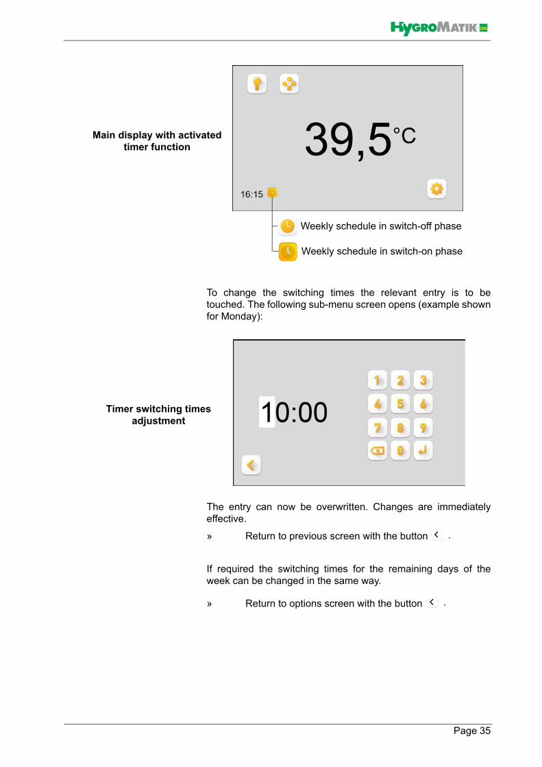
To change the switching times the relevant entry is to betouched. The following sub-menu screen opens (example shownfor Monday):
The entry can now be overwritten. Changes are immediatelyeffective.
» Return to previous screen with the button
If required the switching times for the remaining days of theweek can be changed in the same way.
» Return to options screen with the button
Weekly schedule in switch-off phase
Weekly schedule in switch-on phase
Main display with activatedtimer function
Timer switching times adjustment
.
.
Page 35

SPA
Settings for operating mode "Timer with manual overwrit-ing"For this operating mode it is necessary to activate the "Steamon/off" button on the options screen in addition to timer activa-tion. Steam mode can be manually started and ended howeveronly then when there is a switch-on phase in the weekly sched-ule at the same time. When the timer switch-off point is reachedthe steam supply is switched off. Up to this point in time thesteam supply is continuous as long as a manual switch-off is notmade. The main screen is presented to the user for example asshown below:
Weekly schedule in switch-off phase
Weekly schedule in switch-on phase-"Steam on/off" functionless
-steam mode possible by touching"Steam on/off"
Timer mode with manual overwriting
Page 36

SPA
Settings for operating mode "Timer with manual overwritingand short-term"To select this operating mode an entry for the short-term modeinterval must be made by the operator (see section "Short.termmode" in Section "Manual mode ...setting"), in addition to settingthe timer mode and activation of the steam buttons.
If the steam control is in a timer switch-on phase the steammode starts only after touching the "Steam on/off" button for theduration of the programmed short-term mode interval.
Page 37

SPA
Time settingAs a second setting option on the timer screen the daytime clockcan be adjusted. The clock continues to run as long as the dis-play/button of the clock is not touched. When touched the clockis stopped and the (internal) second counter set to "zero". Forsetting the time the following screen appears:
» With the button return to the previous level is made without changing the time.
If the time setting is to be changed proceed as follows:
» Overwrite the digit at the cursor position by touching one of the numerical buttons on the keyboard (digits not possible to overwrite are darkened); with the entry the cursor moves to the next position immediately to the right.
» Overwrite all digits required by the same method. The cursor jumps back to the far left position after reaching the position on the far right. Deliberate return of the cur-sor to the previous position can be made with the but-ton .
» Use the button to save settings; the clock starts.
If a start is required accurate to the second the operation of thebutton must be synchronized with an external time signal.
» Return to main screen with the button
Time setting
Please note
.
Page 38

SPA
9.4.8 Colour combination selectionFor customizing the appearance of the main screen of the SpaTouch Control one of six colour combinations can be selected bythe operator for the background and font colours.
The colour selection level is retrieved by operating the button on the options screen (see Section "Defining the main screen (options screen)").
» Select the required option by touching one of the six colour combination boxes. The screen changes imme-diately.
» Accept and return to the options screen with the button
Selection of the colour combination
.
Page 39

SPA
10. Technical specificationsMonitor• 5" capacitive touchscreen (PCT touchscreen)• Resolution 800 x 480 pixels• 65K colour saturation• Protection class IP65 front (rear IP00)
Overall assembly (Screen and electronic assembly)• Operating temperature 0 to 55 °C• Humidity: 10 to 60% relative humidity; non-condensing• EMC compatibility: EN/IEC 60730-1
Electronic module• connected to screen by sandwich construction• Power supply 12V AC via data cable (external feed by
steam generator)• RS485 interface for connection to the steam generator
(Modbus RTU protocol)• Protection class IP00 together with screen, but frontal IP65
Page 40

SPA
Dimensions
�����
�����
���
���
���
���
���
�
��
���
118.4
59.2
108
89
Page 41

SPA
Installation well• Steel construction 1.4301
Dimensions
Installation bolts• 2 off countersunk bolts M4 x 8
Face cover• Aluminium black anodized
Dimensions
�����
���
���
���
���
�
��
���
����
����
� ��
Page 42

SPA
This page intentionally left blank !
Page 43

Lise-Meitner-Str.3 • D-24558 Henstedt-UlzburgPhone +49(0)4193/ 895-0 • Fax -33eMail [email protected] • www.hygromatik.comA member of the Group


