SPACE PROCESSING APPLICATIONS PAYLOAD EQUIPMENT STUDY VOL.111. PROGRAMMAT ICS DPD NO. 40 DR NO. MA-04 DCN NO. 1-3-31-00335 CONTRACT N O . NAS 8-28938 JULY' I974 GEORGE C. MARSHALL SPACE FLIGHT CENTER NATIONAL AERONAUTICS AND SPACE ADMINISTRATION MARSHALL SPACE FLIGHT CENTER, ALABAMA 35817 - - --- SYSTEMS TOUP ONE SPniE PARK REDONDC BEACH, CALIFORNIA 93278
Transcript
SPACE PROCESSING APPLICATIONS PAYLOAD EQUIPMENT STUDY
V O L . 1 1 1 . P R O G R A M M A T I C S
DPD NO. 40 DR NO. MA-04
DCN NO. 1-3-31-00335 CONTRACT NO. NAS 8-28938
JULY' I974
GEORGE C. MARSHALL SPACE FLIGHT CENTER NATIONAL AERONAUTICS AND SPACE ADMINISTRATION
This volume i s concerned w i t h the programmatic aspects of the
Space Processing Appl i c a t i o n s Irogram and the methods o f accomodat ing
SPA pay1 oads aboard the Shu t t l elspace1 ab hos t vehic le .
An examination o f the NASA t r a f f i c model shows t h a t there e x i s t s a
po ten t i a l f o r 178 SPA payloads from the o v e r a l l t o t a l o f 727 f l i g h t s
spec i f ied . This could represent up to one quar te r o f the t o t a l Shu t t l e
f l i ghts dur ing the 12-year-'long per iod covered by the Tra f f i c Model . The SPA payload w i l l range from austere f o r shared f l i g h t oppor tun i t ies
t o dedicated where Space Processing w i l l encompass the t o t a l f l i g h t
p y l o a d a1 loca t ions . The majer modes o f use t o SPA w i l l i nc lude dedicated
Spacelab missions, shared Space1 ab missions and shared automated payloads
attached t o the p a l l e t w i t h the necessary con t ro l and d i sp lay equipment i n
the host vehic le .
Several 1 ayout drawings and a r t i s t ' s renderings htve been compl eted
to ill u s t r a t e the v a r i o ~ s po ten t i a l con f igura t ions a v a i l ab le t o accommo-
date the SPA payload equipment. These have inc luded both the two- is le
and arch con f igura t ions i n con jun t ion w i t h the l ong l a b (core segment
p lus experiment segment) and the sho r t l a b (core segment on l y ) , w i t h
i nc l us i on of the SPA supplemental power and heat r e j e c t i o n k i t assembly.
S i x con f igura t ions o f the SPA K i t i n union w i t h automated furnace,
l e v i t a t i o n and core subel emen t s have been examined and drawn up.
Tentat ive senarios revo l v i ng around the prelaunch and post-launch
a c t i v i t i e s have been prepared. Also, a t y p i c a l w a t e r f a l l c h a r t
i l l u s t r a t i n g the poss ib le ground support a c t i v i t i e s i n the prelaunch
phase has been developed.
A major e f f o r t was d i r ec ted toward the establ ishment o f a data bank
f r o m which mission p lanning might be f a c i l i tatod. Pre l iminary computer-
generated p l o t s have shown the bene f i c i a l aspects o f t h i s a c t i v i t y i n the
economical p lanning and usage o f such resources and requirements as power
and energy.
Another aspect o f t h i s tasUs e f f o r t s was d i r ec ted toward i d e n t i f y i n g
payload equipment development and operat ions guide1 ines w i t h the under ly ing
philosophy o f ach iev ing maxiwum cos t e f fect iveness. F ina l ly, cons iderat ion
was given to the schedul i n g of Shutt leISpacel ab/SPA payload ac ti v i t i e s .
2. INTRODUCTION
Various po ten t i a l miss ion modes a re envis ioned as be ing ava i l ab le t o
SPA i n coopera t i o n w i t h the Shutt le/Spacel ab sys tern. The feasi b i l i t y and
u t i l i t y o f the ob jec t i ves o f ear? o f these modes impact both the payload
equipment design requi remen's o x the e f f e c t s upon a v a i l a b l e operat ional
1 im i ts . Payload layou ts ware developed f o r se lected mission modes. Pre-
1 iminary work was completed regard ing SPA shared-fl i g h t oppor tun i t ies on
non-Spacelab f l i g h t s such as those exempl i f i e d by the Ear th Observational
S a t e l l i te (EOS) missions. Vo! jme IID* describes payload equipment necessary
f o r conducting automated yayload f; igh ts .
A1 so considered as a p a r t o f programnatics i s the problem o f d e t a i l e d
analys is and d isp lay o f the myriad data requirements associated w i t h each
a f these se lected mission modes. Pre l im inary work has been completed on
the compu ter-genera ted d isp lays o f these data.
A review of the NASA Shu t t l e t r a f f i c model from 1980-1991 provided a
basis o f es tab l i sh i ng the f l i g h t frequency as a f u n c t i o r ~ of the type o f
payload mode which might be u t i l i z e d .
Pre l i m i nary schedule and a c t i v i t y summaries have been prepared r e f 1 ec t-
i ng contemplated payloads development and opera t ion c r i t e r i a .
*"SPA Supplemental ?ower and Heat Re jec t ion K i t . "
- 2-
3. TRAFFIC MODEL AND FLIGHT OPPORTUNITIES
NASA/MSFC TMX-64751, The October 1973 Space Shu t t l e T r a f f i c Model , dated January 1974, i nd i ca tes t h a t 12 SPA dedicated payloads and 124 shared
payloads are pldnned i n the 1980-1991 Shu t t l e Car50 Manifest . The d i s t r i -
bu t i on o f these SPA payloads i s i nd i ca ted by year on F igure 1 . By us ing the volume and weight c r i t e r i a o f the Shu t t l e ' s cargo bay as
shown i n the f i gu re , 42 add i t i ona l f l i g h t s have been i d e n t i f i e d . Conse-
quent ly, there i s a p o t e n t i a l f l i g h t oppor tun i t y t o t a l i n g 178 (12 + 124 + 42) SPA payloads from the 727 f l i g h t s spec i f i ed i n the NASA Space Shu t t l e
T r a f f i c Model. I f each o f the 124 shared SFA payloads were f lown on separ-
a te Shu t t l e fl igt i ts , the 178 payloads would represent 24.5% o f the Shu t t l e
f l i gh t s contained i n t he 12-year T r a f f i c Model, The SPA modular approach
t o payload accomodat ion i s essen t ia l f o r suppar t ing t h i s frequency o f SPA
on-orbi t experiment operat ions. Without modu la r i t y i n SPA equipment 1 ay-
out , the 124 planned shared SPA payloads and the p o t e n t i a l 42 add i t i ona l
SPA payload f l i g h t oppo r tun i t i es could n o t e x i s t .
F l i g h t oppor tun i t ies associated w i t h sate1 1 i t e deployment o r s e r v i c i n g
missions requ i re SPA payloads which can operate i n an automated mode.
Representative o f t h i s c lass o f miss ion i s the EOS demonstration f l i g h t .
Twenty add i t i ona l EOS operat ional se rv i ce f l i g h t s are planned w i t h i n the
bas ic t r a f f i c model. Being se l f -con ta ined and w i t h i n a1 lowabl e weight and
volume cons t ra in ts a l lows the SPA k i t t o occupy the OMS l o c a t i o n i n the
Shu t t l e cargo bay. Periods o f minimum Shu t t l e maneuvering dur ing such
missions ( ranging from a few hours up t o several days) permi ts the SPA pro-
cessi ng a c t i v i t i e s t o be accommodated. Each miss ion accommodation f u r t h e r
requi res examination o f center o f g r a v i ty (cg) c m s t r a i n t s and thermal
i n t e r a c t i m s w i t h the pr imary payload. Such "piggyback" f l i g h t s wherein
the SPA k i t can be convenient ly accomnodated w i t h i n the cargo bay n o t on ly
increases the SPA f l i g h t frequency ob jec t i ve , b u t enhances the r e t u r n
from the Shut tl e Sys tem Opera ti on.
SPA SHARED MISSIONS' PALLET
OPPORTUNITIES
.CRITERIA FOR SELECTING "SPACE AVAILABLE FLIGHTS WHERE SPA PAYLCADS COULD BE ACCOMMO@ATE~'.
I I TEN FEET OF S U N N I N G LENGTH IS AVAILABLE IN SHUTTLE C. IRGO BAY. 1 ) SHUTTLE PAYLOAD UP WEIGHT DOES N O I PRESENTLY EXCEED 53,000 LBS . 3) SHUTTLE PAYLOAD LANDING WEIGHT DOES NOT PRESENTLY EXCEED 23,000 LBS.
F igure 1 . Summary o f Planned and Poten t i a1 SPA Space Missions f r ~ m 1980 through 1991
4 . PAYLOAD ACCOMMODATION
SPA payload con f igu ra t ions ranging from aq i n d i v i d u a l subel ement f 9 r
a shared miss ion t o groups o f subelements f o r dedicated missions have been
r e f l e c t e d t h r o u g h w t the study. Furthermore, t he d e f i n i t i o n o f a k i t t o
supplement Spacelab manned missions o r ta implement automated missiotis was
accompl i shed . 4.1 MiSSION ALTERNATIVES
Po ten t i a l a1 t e rna t i ves a v a i l ab le f o r accommodating SPA payloads i n
the Shu t t l e O r b i t e r System are summarized i n Figure 2. From a payload
p l m n i r ~ g standpoint , Conf igurat ions 1 , 2 and 4 represent the p r i n c i p a l
accommodation modes considered i n t h i s study. The remaining p o s s i b i l i t i e s
were no t t r ea ted i n d e t a i l .
As shown i n Sect ion 3, an ana lys is o f t he S h u t t l e t r a f f i c model pro-
vides a r a t i o n a l e o f the poss ib le u t i l i z a t i o n and type o f SPA f l i g h t oppor-
t u n i t i e s which might be a v a i l ?b le .
I t should be emphasized t h a t f o r cu r ren t planning, the s l~ggested SPA
f l i g h t frequency would o n l y be implemented cons i s t en t w i t h the growth o f
technica l ob j ec t i ves and program resources.
Independent technica l vol3mes regard ing payl oad accommodations in terms o f subsystem i n te r f aces a re presented i n Volume I I. These i nc l ude
power, heat t r ans fe r , EMC, data a c q u i s i t i o n and process con t ro l and the
SPA K i t . Reference t o the appropr ia te document t i t l e s may be made from
the 1 i s t i n g i n the Foreword o f t h i s volume.
4.2 SPACELAB CONFI GURATIONS
During the Phase i study e f fo r t s , two modular payload subelement con-
cepts were se lected t o i l l u s t r a t e i n t e g r a t i o n o f the SPA equipment i terns.
Both approaches prov ide management of the equipment and host veh i c l e i n t e r -
faces b u t s t i l l a l l ow f l e x i b i l i t y i n addressing the a1 t e r n a t i v e miss ion
oppor tun i t i es . I n i t i a l l y the host veh i c l e t h a t was consfdered du r i ng Phase
I was the U. S. S o r t i e Lab c o r f i g u r a t i o n . Th is fea tu red G f i x e d 6 m (20 f t )
s ide wa l l length.
I 1 1 u s t r a t i v e payload 1 ayouts showing the b u i l d-up 9 f payl oads us ing
e i t h e r a "dual - i s l e " o r "arch" modular subel ement approach were prepared.
I. D
ED
ICA
TE
D S
PA
CE
LAB
h"5
SIO
N
2.
SH
AR
ED
SP
AC
ELA
B M
ISS
ION
3.
MIN
IMU
M IM
PA
CT
CA
RR
Y-O
N
(LIK
E A
PO
LL
O F
LYO
AC
K)
4.
SH
AR
ED
AU
TO
MA
TE
D P
AY
LO
AC
AT
TA
CH
ED
I m
T
O P
ALL
ET
WlT
H N
EC
ES
SA
RY
CL
<
TR
OL
AN
D
DIS
PLA
Y E
QU
IPM
EN
T I
N S
PA
CE
IAB
OR
SH
UTT
LE
5.
MIN
IMU
M IM
PA
CT
CA
RR
Y-O
N
AU
TO
MA
TE
D
PA
YLO
AD
AT
TA
CH
ED
TO
P
ALL
ET
WIT
H
NE
CE
SS
AR
Y C
ON
TR
OL
AN
D D
ISP
LAY
EQ
\JIP
- M
EN
T IN
SP
AC
EIA
B O
R S
HU
TTLE
6.
MIN
IMU
M I
MP
AC
T C
AR
RY
-ON
AU
TO
MA
TE
D
PA
YLO
AD
LO
CA
TE
D I
N C
AR
GO
BA
Y W
lTH
N
EC
ES
SA
!?"
CO
NT
RO
L A
ND
DIS
PLA
Y E
QU
IPM
EN
T
IN 'i
HU
7ii
E
1 .
. .
. ;::
- .
: SP
:?C
E Pl
?..C
CE;
SI
NG
PA
YL
CA
D
k-; .
;
::--,
*DE
Liv
ER
Y/R
ETR
I E
VA
L O
F A
UT
OM
AT
ED
SA
TELL
ITE
S
NO
T I
h'C
LU
DE
D
-8
.-'> ,.
Fig
ure
2.
Po-
:ent
i a1
Mis
sio
n M
odes
fo
r A
ccom
noda
ti ng
Spa
ce
Pro
cess
i ng
Pay
load
s*
During Phase 11, the Europeatl Spacelab study had progressed t o the
po in t where payload accormlodations were addressed which u t i i i zed the Space-
l ab Core Segmevt (Short Lab) o r the conbination o f Core Segment p lus
Experiment Segment (Long Lsb). The nominal side-wall length o f each o f
these segments i s about 3 m (10 ft.!. Sumnary data regarding the baseline
Earopean Spacelab desigr! i s provided i n F igur ts 3 and 4 along w i t h se-
lected sumary dsta based upon a d id icated SPA payload.
The NASAIESRO base1 i ne Spacelab conf igura t io t~ i s defined i n Figure 3 . Shown i n Figure 4 i s the Spacelab Long Module and one sector o f the Space-
l a b Pa l le t , and also indicated i s the space ava i lab le i n the pressurized
mdu l e f o r experiment-unique and general -parpose mission equi yclent.
Figure 3. NASA/ESRO Spacel ab Configuration D e f i n i t i o n
The SPA dedicated payload w i l l requi re use o f both the Core Sewent
and the Experiment Segment ( together ca l l ed the Long Mod~le!. The p a l l e t
sector may be used to s t r u c t u r a l l y sustain the SPA supplemental Power and
Heat Rejection K i t . This k i t , which i s necessary to meet SPA e l e c t r i c a l
power and thermal control requi rements tha t exceed Spacel ab capabi 1 i ti es , i s described i n Volume I I D .
Using the Spaceizb dimensions, selected accomnodation layouts were
made These are summarized -in the composite drawings shown i n Figure 5.
By use o f the Core Segment iFhor t Lab) and the dua l - i s le approach, f o r
example, a subelement such as 6iology can be accomnodated. Use o f the SP.P
K i t i n coojl:~iction w i th e i t h e r the Short o r Long Lab would be dependent
upon the experiments and payloads contemplated f o r a p a r t i c u l a r mission.
7 I S U F P O ~ T 1 EXPER~MENT
L , B L K H 3 1 SECTION 1 SECTION
LEI\.GTH. 'r. 3 84 3
- V~EIGHT 204 3726 1.055
lh : [ (LEO 1 18.229 1 12.3271
AFT SLKHD.
0.84 ( 2 751
234 14501
P L EQPT rn3 '
INTER FACE
-
204 14501
7 2;7
10.2 1360!
. PALLET
4
-
3 ,lo'
3 3 3 I ; l ,101 1 101 1 113 7 1
37'5 375 ' 375 375 / 3i5 I I 18261 ,826, 18261 ,8261 i 526, ,
SP
AC
ELA
B
SUBS
YSTE
MS
EQ
U lP
T
SPA
GE
NE
RA
L PU
RPO
SE /F
UR
NA
CE
S
UB
ELE
ME
NTS
SPA
BIO
LOG
ICA
L A
ND
CO
RE
S
UB
ELE
ME
NTS
SP/
fOW
ER
AN
D
:ltA
T R
EJE
CT
ION
K
IT
SP
AC
ELA
B
SPA
DU
AL
ISLE
SU
BSYS
TEM
S S
UB
ELE
ME
NTS
I CORE S
EG
ME
NT - 3
M
EX
PE
RIM
EN
T S
EG
ME
NT
\ \
AU
TO
MA
TE
D
\ S
PA
CE
LAB
\
SPA
DU
AL
SP
A FU
RNAC
E A
ND
LE
VIT
AT
ION
SU
BSYS
TEM
S IS
LE C
ORE
AN
D
SU
BE
LEM
EN
TS
B
IOL
OG
Y
SU
BE
LEM
EN
TS
.*I" 'I
ra
5
Fig
ure
5.
Acc
omnc
4atio
n M
odes
of
SPA
Pay
load
Equ
ipm
ent S
P~
E
LAB
SP
A D
UA
L IS
LE
SUBS
YSTE
MS
SUBL
LE
ME
NIS
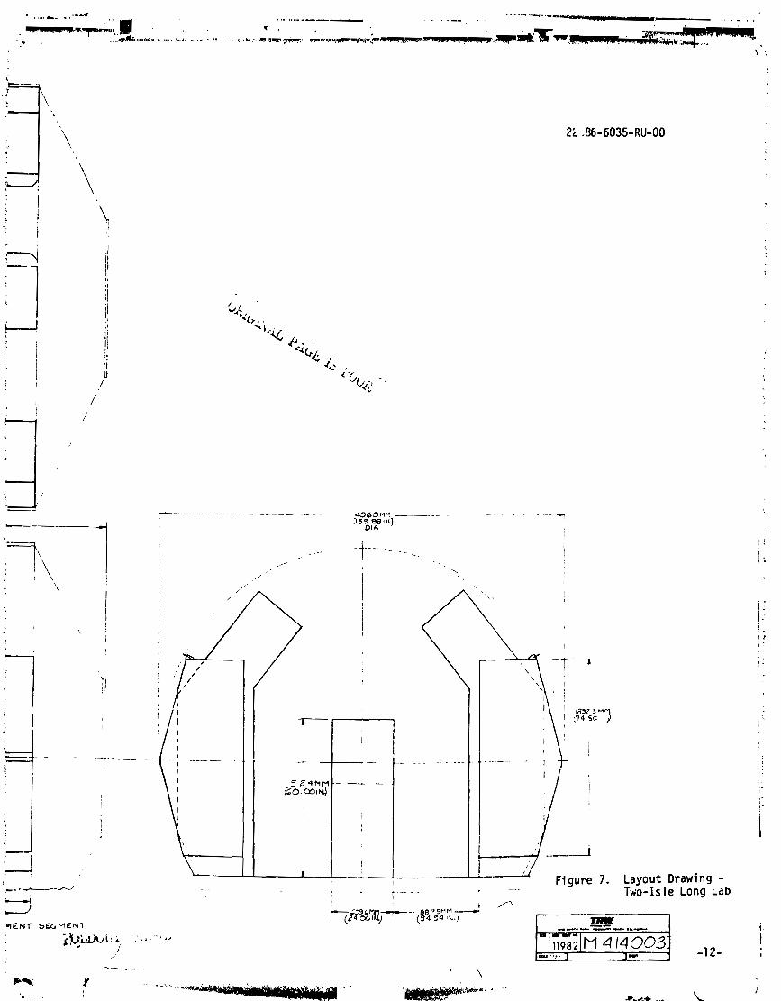
Layout drawlngs (Figures 6 and 7) f o r the dua l - i s l e approach were prepared
f o r both a Long and Short Lab. S im i l a r l y i n Figi i re 8, the arch configura-
t i 0 7 i s shown i n a Long Lab. UD t o two arch segments may be acconmdated
i n t h i s manner. Figure 9 sumnarizes the major elements involved i n a dual - i s l e Long iab, inc lud ing an attendant SPA K i t . S im i l a r l y , Figure 10 shows
two payloads i n the arch conf igurat ion. The basic layouts o f the modular
payload stibelements tha t were prepared i n Phase I are completely su i tab le
to adaptation o f the Spacttlab conf igurat ion. The two arch con f i gura t i ons
used f o r the accomnodation i l l u s t r a t i o n w i t h the Long Lab are presented i n
Figures 11 and j2. The dua l - i s le layouts are n o t shown. The on ly a1 tera-
t i o n necessary was a s l i g n t reduct ion i n rack width i n the dua l - i s l e con-
sole.
As shown i n several o f the previous f igures, a SPA K i t i s incremental
t o SPA payload accomnodations. Several SPA Power and Heat Reject ion K i t
packaging concepts have been i d e n t i f i e d . A comprehensive 5escr ip t ion i s
provided i n Volume I I D . The k i t i s intended t o be an augmentation capabi-
l i t y when used i n connection w i t h the power and heat r e j e c t i o n capacity of
the Spacelab. The k i t may a lso be used w i t h the automated furnace, l e v i -
t a t i o n an3 core equipment t o form payloads f o r the automated mission mode.
A number o f packaging 1 ayou t s , cornbi n i ng the k i t and au toma ted experi - ment equipment modules, have been prepared.
As i l l u s t r a t e d by Figure 13, Configurations 1, 2, 4 and 5 represent
a1 terna t e themes o f packaging the power and heat r e j e c t i o n subsystem equip-
ment and exper i renta l payloads by modular approaches. For theqe four con-
f igurat ions, the geometry considered u t i l i z e s a r i g h t cy l i n d r i c a l s t ructure.
Configuration 3 u t i l izes a standard pal l e t sect ion as a base f o r incorpor-
a t i n g the SPA K i t hardware. Prime packaging factors ccmsidered were:
r An a l l oca t i on f o r a spec i f ied weight and volume of experimental
payload equipment was established.
a In tegra t ion o f both the payload and subsystem equipment has t o be
modular i n order to preserve serv ic ing and reconf igurat ion a ttri - butes necessary f o r frequent re-use and a1 te ra t ion .
e Placement o f the modular elements w i t h the s t ruc tu ra l conf igura-
t ions were based upon:
, . .
. . . ~. . .~ . 4 SEGMENT
Figure 6. Layout Drawing - Two-Isle Short Lab
Figure 7. Layout Drawing - -. Tvio-Isle Long Lab
,qENT SEGMENT
s u a s r s r ~ n i R A C K S
N l F i g u r e 8. Arch Layout Conf igurat ion Drawing - I HI Long Lab
SP
AC
EiA
B
SUB
SYST
EMS
EQ
U IP
T
SPA
GE
NE
RA
L PU
RPO
SE /F
UR
NA
CE
SU
BEL
EMEN
TS
SPA
BIO
LOG
ICA
L A
ND
CO
RE
SUB
ELEM
ENTS
SPA
POW
ER A
ND
H
EAT
RE
JEC
TIO
N
KIT
FU
RN
AC
E
) CO
RE S
EG
ME
NT - 3
M
) EX
PER
IMEN
T S
EG
ME
NT - 3M
KIT
CO
RE
S
UB
ELE
MN
T
BIO
LO
GIC
AL
SU
BELE
MEN
T /
Fig
ure
10.
A
rtis
t's
Ren
deri
ng o
f Lo
ng L
ab A
rch
Co
nfi
gu
rati
on
k-.
-*
--..
* ~
, -. . 9
.
- ., . ,?
.%
- =.e-7"
, .
-- .. .*.s
-.
$ .. *
. .
... .
. - -
. ,
. , .,
.,, ,
. '
.'
- --..
. . ."
,".
.+ ..
- -.., , , ..
..
;' .,
-i.
..-.
,., *
- -
. I ., .
.. . .
-,
.1
<_
-
- .,
.
, ~
,...,%
..... .. :
CORE SUBELEMENT -\,
YIlle-
WID SUULY S Y S R I I
t lQ
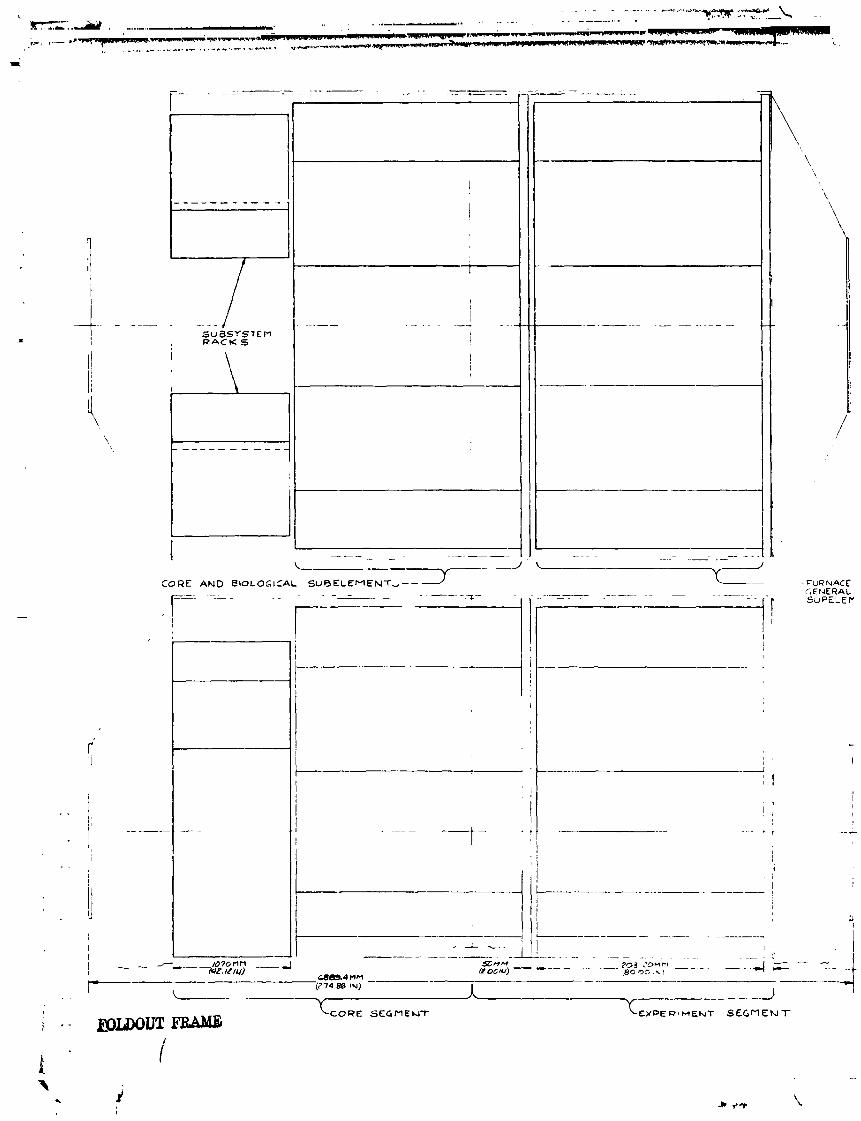
F igu re 11. Core and B io l ogy Subelements - Arch Conf igu ra t ion
FLOOR L lkE
\ - - BIOLOGICAL SUBELEMENT
PURPOSE
I o . ~ A w I A B C Q I O ( I Q
Figure 12. Furnace and General Purpase Subelemnts - m r
Arch Configuration
: l a m - . CP
- Feasi b i l i ty o f thennal control
- Abi l i t y to integrate and reconfigure
- Haintaining center of grav i ty (cg) control (ax ia l and rad ia l
a Use as both an augmentation system w i th Spacelab o r as en autono-
mous system f o r automated missions.
a Possible weight and ax ia l length constraints on tne shared payload
mission opportunities.
4.3 MISSION PLANNING
Development o f the ear ly f l i g h t payloads must be consistent w i th the
host vehicle development. This i s necessary i n order to proceed w i th the
necessary interface resol ut ions between the SPA pay1 oads and the fl i g n t
hardware system. The influence o f the payload operator on the user roles
i n the projected operational issues must a1 so be developed. The act ive
par t ic ipat ion o f the technical comnuni t y through issuance o f Advmced Plan-
n i ng Opportunities ( APO) and Advanced Fl i g h t Opportunities (AFO) i n se t t i ng
requirements w i 11 be c r i t i c a l t o the SPA payload def in i t ion.
From a programmatic standpoint, i t i s desirable t o establ ish the
payload-subelernent/host-vehicle interfaces as ear ly as possible while pm-
tect ing tne options o f varying the f i n a l design requirements f o r the equip-
ment items ccntained i n the subelement themselves. This philosophy i s
completely consistent w i th ~ l l o w i n g equipment items t o cnange without i m -
pacti ng the hos t -vehic l e interface. Such changes w i l l necessarily fol low
as requi rements and objectives s h i f t throughout a h:ul t i -mission program.
This approach a1 1 ows the SPA payload development t o proceed concurrently
with the Shutt le and Spacelab without the necessity c f a1 1 the f i n a l equip-
ment i tems a1 so be? ng evolved. Systms level engineering a t the payload
sube:ement leve l w i l l provide a means of f i n a l i z i ng the host-vehicle/pay-
1 oad interfaces and v i l l necessarily a f f e c t the f i n a l equipment and appara-
tus designs as they unfold.
4.3.1 Prelaunch and Post-Launch Ac t i v i t i e s
Many facets i n the to ta l mission planning senario w i l l occur i n the
implementation o f the SPA program. Elements o f tke payloads related ac t i -
v i t i e s arc? i den t i f i ed by Figure 14. From the payloads standpoint, pre-
. . launch and post-launch operations present obvious phases. While not
d e f i n i t i z e d i n the f igure, the steps and ro les o f the ex3eriment d e f i n i t i o n
and payload spec i f i ca t ion a c t i v i t i e s are v i t a ? l y important. Figure 14
i l l u s t r a t e s what may be considered as t yp i ca l a c t i v i t i e s when the f l i g h t
program becomes operat ional. Simi lar ly , the diagram road maps steps which
must be conducted i n the i n i t i a l establishment o f the f i r s t payloads and
the operational aspects.
The water fa l l s of Figure 15 fu r the r d e f i n i t i z e possible ground support
a c t i v i t i e s i n the prelaunch phase.
T i ~ e estimates which have been indicated f o r ind iv idua l steps w i l l be
studied and d e f i n i t i zed under a jus t -s tar ted 5-month study TRW i s conduct-
i n g for NASA/KSC, e n t i t l e d Space Processing Launch S i t e Operations (Con-
t r a c t NAS 10-8606).
4.3.2 Data Analysis
Conducting an ongoing mu1 ti -mission SPA procram necessitates t h a t
rout ine change o f experiments and payloads regu la r l y occur. I n i t i a l steps
have been made to i d e n t i f y prel iminary approaches wherein various experi-
ment and equipmnt charac t e r i s t i LS can be logged and re t r i eved by computer
methods t o support payload planning o f the essential features.
For each mission mode selected, overa l l layouts must be prepared
which ill ust ra te the payload equipmentfhost vehic le accommodation. Due t o
the enormous number o f d i s t i n c t combinations o f experiments t h a t may be
performed i n the various ant ic ipated mission modes. a deta i 1 ed analysis
o f the data requirements involved i n each case i s mandatory. By using the
resu l ts of t h i s program i n the planning o f the experiment time1 ines, be t te r
usage o f the f a c i l i t i e s ava i lab le may be made.
A f te r developing t h i s p lethora of data, a means must be found by which
an e f f e c t i v e d isplay may be prepared. A successful method o f doing t h i s
has been found and involves the computer generation o f three-dimensional
bar graphs.
A TRW Systems computer Frogram named BG3D mckes a graphical d isplay
o f a set o f pos i t i ve numerical values t h a t are assigned to the separate
g r i d squares o f a ractangular gr id. On every g r i d square t h a t has a non-
zero funct ion value, a bar i s erected t h a t i s d i r e c t l y proport ional to the
value o f the func t ion there. The method o f performing t h i s i s as fol lows:
I N T O I S P A C C W I 1 DAY
CHECKOUT SUISYSIEMS O F I EF 1 DAY
EF.MPONMENTU T D l l N G AS NEEDED 4 D A V I
MlSSlCN SIMULATION
I WITH c m I DAY
DISCONNEC~J I
G S m 6 AND PR€PAU m u
I TRANSFER I DAY 1
TuANsFm SPACE LAB
INSTALL (PACELA9
+.-~CIJNO SIJPPCRT F C U t P M i h l LAUNCH PROCESSING IVStEM
Figure 15. Typical I n teg ra t i on Schedule f o r SPA Payload
a p a r a l l e l p ro jec t ion o f the g i r d l b a r system i s made onto a plane, hidden
1 i nes are removed and the resul ti ng p ro jec t i on t h a t includes r o w and
column labels i s p l o t t e d by a Cal Comp p l o t t e r . This procedure provides
a h igh ly e f f e c t i v e method o f v i sua l i z i ng a vast s e t o f data -- much b e t t e r
than by reading a matr ix.
By using the BG3D program and the data base managemellt program (see
the Appendix) developed f o r SPA, a comprehensive study may be made of the
many data requirements. Those s ingled o u t and analyzed i n i t i a l l y a re
power, energy, weight and volume. Others t h a t may be analyzed as the SPA
program progresses i ncl ude heat re jec t ion , source power requi rements , electromagnetic compat ib i l i ty , data management, etc.
4.3.2.1 F i l es
Several f i l e s must be establ ished from which data may be drawn i n
order t o i n i t i a t e the p lo ts . These are described below.
Equipment F i l es
For each k iece of equipment i n the SPA inventory, a separate data
record i s establ ished which includes weight, vol ume and power p r o f i l e .
I f the equipment has both a sustained and peak power l eve l , both are
specif ied.
Experiment F i l e s
For each experiment to be performed, a separate data record i s
establ ished which includes a 1 i s t o f each piece o f -2uipment used and
i t s s tar t -up and shut-down times.
Mission F i l es
For each mission considered, a separate data record i s establ ished
which includes the experiments heing performed and t h e i r s t a r t times.
4.3.2.2 P lo ts
Bu i ld ing upon the in format ion contained i n the data bank, several
types of compu ter-generated p l o t s may be made.
4.3.2.2.1 Commonality Mat r ix
The f i r s t p l o t developed i s i n the form of a mat r ix t ha t shows which
equipment items are needed to perform each experiment. Experiments, l i s t e d
by i d e n t i f i c a t i o n numbers, are shown across the upper hor izonta l ax is wh i le
the equipment iteins are l i s t e d v e r t i c a l l y . Where an apparatus i s used
i n an ind iv idua l experiment, an X i s p l o t t e d by the computer. This char t
may be c a l l e d upon t o l i s t a l l equipment and experiments o r on ly those
from a p a r t i c u l a r subel ement o r combination thereof.
4.3.2.2.2 Power P lv ts
I n order t o make maximum usage o f the power t h a t w i l l be ava i lab le
t o be used by SPA, a comprehensive and deta i led analysis i s necessary.
This analysis makes use o f the power requirements t h a t are held i n the
data bank f o r a l l the equipment items t h a t are needed to perform each
experiment. Numerous d i f f e r e n t experiments have been ant ic ipa ted to be
performed w i t h i n the four experiment subelements.
Combining the power versus time f i l e s o f each experiment resu l t s i n
a three-dimensional bar graph t h a t has the experiment time and the equip-
ment i terns as the coordinates. The bar height, therefore, represents the
power requirements. I n t h i s manner, bar graphs may be developed f o r each
experiment. The BG3D program al lows f o r the add i t i on o f a " t o t a l s " column
and row; therefore, a row t h a t shows the t o t a l amount o f power as a func-
t i o n of the t ime i s included. This i s i l l u s t r a t e d schematically i n Figure
16.
BARS=POWER (1 inch = 1 k i l o w a t t )
m- Experi~nent Time (Hours)
Figure 16. Power as a Function o f Equipment and Experiment Time
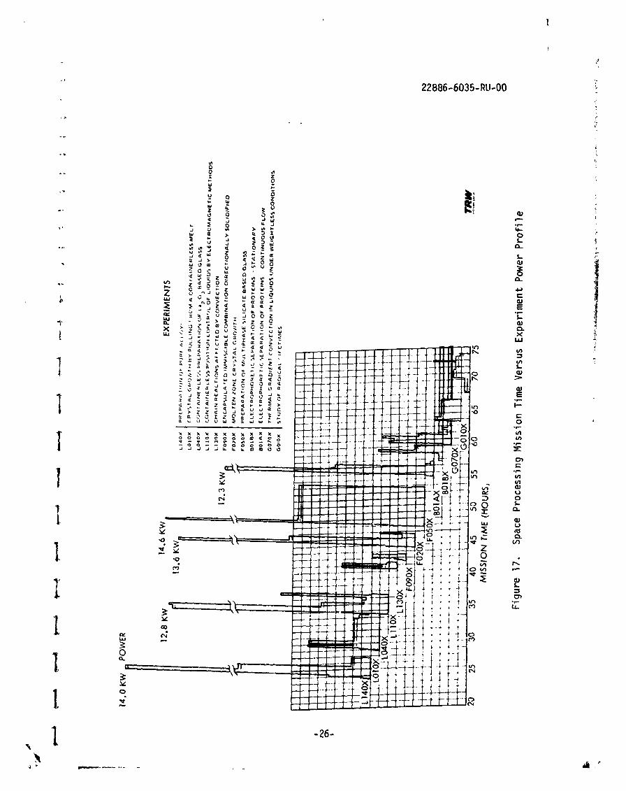
A f t e r h a v i ~ g developed a power requirement time1 i n e f o r each experi-
ment, i t i s then possible t o address the problem o f developing a t o t a l
mission t imel ine. There are a mul t i tude o f possible combinations o f
experiments t h a t can be performed i n any mission. Bar graphs can be made
f o r each t h a t shows the cumulative power requirements (bar height) f o r
each experiment (ordinate) as a funct ion o f mission t ime (abscissa). This
i s i l l u s t r a t e d i n Figure 17. A r o w may be included t o show the t o t a l power
requirements f o r the mission due t o the SPA payload i f several experiments
run concurrently. This may then be p l o t t e d on a two-dimensional graph o r
read o u t o f the computer and the in format ion i s then used i n ca l cu la t i ng
the energy requirements.
4.3.2.2.3 Energy P lo t s
Another important aspect o f the data analysis addresses the problem
o f t o t a l avai lab le energy t h a t i s needed Lo accomplish the selected com-
b ina t ion o f experiments. This po r t i on o f the study u t i l i z e s the r e s u l t s
o f the power p lo t s mentioned previously.
The fo l lowing re1 at ionship holds t rue:
where E = energy
P = power
t = time
Since the f i l e s contain the power as a funct ion o f t ine, the energy
w i l l be determined by performing the respect ive sumnations during the
time periods i n which the equipment items are being used. The resu l t s of
these calculat ions are read i l y displayed by use o f the BG3D program. The
energy needed (bar height) as a func t ion of apparatus (abscissa) and ex-
periment (ord inate) may be p l o t t e d such as i s i l l u s t r a t e d i n Figure 18. A
column may be added which 1 i hewi se may be added to determine the t o t a l
energy requi red to accompl i s h the mission.
f a U l PMEWT HUMBER
Figure 18. Mission Energy Bar G,aph
-27-
5. PAYLOAD EQUIFENT WORK BREAKDOWN STRUCTURE
This section contains elements o f the payload equipment development
and operations w i d e l i nes which have guided the technical approaches,
concepts and requirements i den t i f i ed throughout the en t i re study e f fo r t .
A t the forefront has been a phiiosophy to achieve maximum cos c e f fec t ive-
ness inherent t o the approaches considered.
The space processing payload philosophy pmvides f o r accomdat ion
of a wide variety o f mission purposes through an integrated program o f pay-
ioai quipment develop lent.
This epproa :I i s intended to minimize cost through the order ly design
and fabr icat ion o f payload subelements wherein substantial cost benefits
resu l t from:
1 ) Equipment commonal i t y between subelement types.
2) Modularity f o r payload integrat ion and subelement types.
3) The use o f comnercial equipment techno1 ogies whenever possi b l e.
4) Reuse o f equipment and use i n mny f l i gh ts .
Design f o r comnonality, modularity and comnercial equipment was
empkasi zed throughout the study.
Tabie 1 l i s t s areas of potential high costs and of fers ways tha t these
costs might be minimized.
Continuing another aspect o f ear ly de f i n i t i on of pay1 oad' s develop-
ment, a Work Breakdown Structure was instructed.
The SPA Work Breakdown Structure (WBS) was designed t o funct iona l ly
display the uni ts o f work that form a framework f o r management and control
o f hardware devel opmnt, technical software, schedul e p l ans and status,
and cost accumulation. This i s shown i n Figure 19 as a product and ser-
vices oriented family tree. The un i ts of work are subdivided to Level 4
on the f igure i n order t o form manageable elements f o r which there are pre-
cise d e f i n i t i o n ~ , and f o r which schedules and resource appl icat ion es t i -
inates can be prepared and displayed i n reportable packages.
Cost c r i t e r i a i n design and opera- t iona l trade studies
Fu l l u t i l i z a t i o n o f shu t t le capa- b i l i ty
Shared missions
Cost C r i t e r i a
I SPA
CE
PU
OC
ES
IIN
G
AP
PLI
CA
TIO
FlS
P
AY
LC
AD
EO
UIP
ME
PIT
I
Fig
ure
19.
SP
A W
ork
Bre
akdo
wn
Str
uct
ure
6. SCHEDULE CONSIDERATIONS
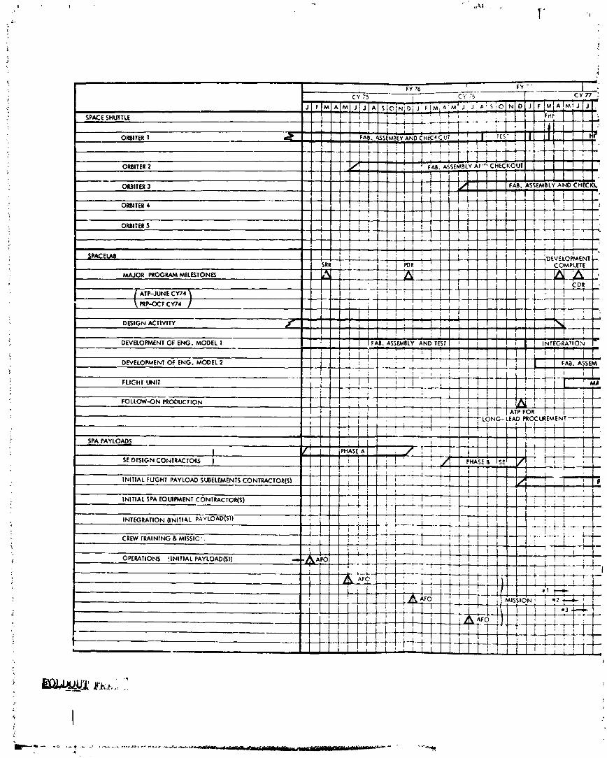
An overview o f the schedule i s presented i n Figure 20. The develop-
ment o f the ear ly missions and associated payloads are expected to involve
longer cycles w i th the l a t t e r missions re f lec t4 ng shorter times. The
1 a t t e r i s predicated upon processes, procedures and reuse ref i nements
~ccu r r i ng , which w i l l a1 low "quick-reaction" cycle times between de f i n i t i on
of a new set o f mission objectives and i t s accomnodations.
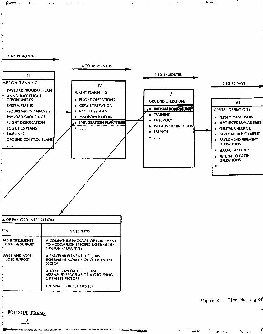
Seven steps o f Shutt le payload a c t i v i t i e s are shown i n Figure 21 ni t h
an estimate o f the time associated w i t h each step. The Space Processing
Shutt le payload(s) w i l l need to employ the actions dep?'cted w i th in these
seven ac t i v i t i es ; however, ways and means should be found t o a? low p r inc i -
pal investigators, users and payload operators t o enter t h i s chain o f
events a t cer ta in points downstream without having to s t a r t a t the f i r s t
a c t i v i t y po in t each time i t i s desired t o conduct an on-orbi t space pro-
cessing research pro ject . Related and past space processi ng experience,
payload equipment modularity and the concept o f a space laboratory f a c i l i t y
can allow entry i n t o the chain, f o r re lated experimentation, a t log ica l
points so tha t quick-reaction techniques can be a feature o f the space p ro -
cessing program.
?
SPA PAYLOADS
! SE DESIGN COt<TRACTORS 1
INITIAL FUGHT PAYLOAD SIJBELWENTS CONTRACTOR(S)
INITIAL SPA EQUIPMENT CONIRnCTOR(S)
INTEGRATION (INIT14L p.4yLOAD6))
CREW lRAlNlNG d MISSIC'.
OPERATIONS {INITIAL PAYLOAD($))
t-
PROGRAM SCHEDULE
Figure 20. Overview o f Shuttl elspace1 ab;'
Figure 20. Overview o f Shut t l elspace1 ab/SPA Program Schedule
-32-
1 TO 2 YEARS
2 TO 3 YEARS tr
lNlTlAT ION
USER NEEDS 0 REQUIREMENTS
FEASlBlLlTY
0 MERIT ASSESSMENT
0 OVERALL OBJECTIVES
0 COST ESTIMATES
...
0 EXPERIMENT DEFINITION
EXPERIMENT ANALYSIS/DESIGN
0 EQUPMENT SELECTION EXPERIMENT DEMLOPMEI
EXPERIMENT SUPPORT
a COST ESTIMATES 0 PAYLOAD
ACCOMMODATION ...
-
Ill MISSION PLANNING
0 PAYLOAD PROGRAM7
ANNOUNCE FUGHT: OPPORTUNITIES
SYSTEM STATUS a REQUIREMENTS ANP~
a PAYLOAD GROUPIN(
0 FLIGHT DESIGNATIC ;
0 LOGISTICS PLANS TIMELINES
a GROUND CONTROL
... I
INTEGRATION LEVEL
C
I v
Ill
I t
I
EQUIPMENT - - -- -
ASSEMBLY OF PAYLOAD INSTRUMENTS AND THEIR GkNERAL PURPOSE SUPPORT EQUIPMENT
ONE OR MORE PACKAGES AND ADDI- TIONAL GENERAL PURPOSE SUPPORT EQUIPMENT
SPACELAB ELEMENTS
SPACELAB
4 TO 12 MONTHS
6 TO 12 MONTHS
3 TO 12 MONTHS
7 TO 30 DAYS 7--
IMISSION PLANNING
,- PAYLOAD PROGRAA? PLAb
': ANNOUNCE FLIGHT b OPPORTUNITIES
' SYSTEM STATUS
REQUIREMENTS ANALYSIS
, PAYLOAD GROUPINGS
. FLIGHT DESIGNATION
:. LOGISTICS PLANS
< - TIMELINES
GPOUND CONTROL PLAN
FLIGHT PLANNING
a FLIGHT OPERATIONS
a CREW UTILIZATION
a FACILITIES PLAN
--
v I ORBITAL OPERATIONS
0 FLIGHT MANEUVERS . RESOURCES MANAGEMF:
0 ORBITAL CHECKOUT ,
0 PAYLOAD DEPLOYMENT
PAYLOAD/EXPERIMENT OPERATIONS
0 SECURE PAYLOAD
0 RETU'N TO EARTH OPERATIONS
...
a MANPOWER NEEDS
, IWGRAtMM m ~ w
GOES INTO
.a OF PAYLOAD INTEGRATION
. )AD l NSTRUMENTS , PURPOSE SUPPORT
:AGES AND ADDI- . OSE SUPPORT
r
I
A COMPATIBLE PACKAGE OF EQUIPMENT TO ACCOMPLISH SPECIFIC EXPERIMENT/ MISSION OBJECTIVES
I
-
A SPACELAB ELEMENT: I.E.. AN EXPERIMENT MODULE OR ON A PALLET SECTOR
A TOTAL PAYLOAD; I. E., AN ASSEMBLED SPACELAB OR A GROUP1 NG OF PALLET SECTORS
THE SPACE SrlUTTLE ORBITER
Figure 21 . Time Phasing o f
-
3 TO 12 MONTHS - GROW40 OPERATIONS
TRAINING 0 CHECKOW
e PRELAUNCH FUNCTIONS r LAUNCH
...
7 TO 30 DAYS
1 TO 18 MONTHS
, - ORBITAL OPERATIONS VII
PAYLOAD/EXPERIMENT - OPERATIONS
SECURE PAYLOAD
RETURN TO EARTH OPERATIONS ...
COMMUNlCATtONS GROUND PROCESSING DATA DlSTRlBUllON DATA ANALYSIS
...
FLIGHT MANEUVERS DATA MANAGEMENT RESOURCES MANAGEMEN
0 ORBITAL CHECKOUT 0 ACQUISITION
PAYLOAD DEPLOYMENT O N BOARD PROCESSING 1 I
Figure 21. Time Phasing of Shu t t l e Payload A c t i v i t i e s
USERS ' G U I D E ?OR 3 - D PLOT DATA BASE +NAGE:.LEILI PR0GE.M . . . . . . . . . . . . . . . . . . . .
I,() GENERAL DESCRIPTIOtI
The 3-D P lo t Data Base Management Program i s used onl ine ( i n t c r -
ac t ive ly ) from a terminal t o c r e a t e and update da t a f i l e s and Senerate
output t o be plo t ted and l i s t e d . Af te r the user has loaded the pro-
gram i t w i l l p r i n t
ENTER ~0tl?lA~i) (FILE, EDIT,LSTF, STIDS , P L ~ T , E ~ K C N )
?
The user responds with a f i l e l e v e l connnand. There a r e s i x f i l e
l e v e l comands:
and s i x record l eve l comands under the EDIT command:
A ~ y t i m e h e program expeccs tne user t o respona, a prompter ? ~1.1;
be pr in ted i n the f i r s t pos i t i on of the l i n e . The respcnscs, e x c e p t
f o r t i t l e information, a r e f r e e form (blanks a r e ignored). A 1 1 2iira-
meters on the commands a r e enclosed i n brackets t o show t h a t they a r e
opt iona l .
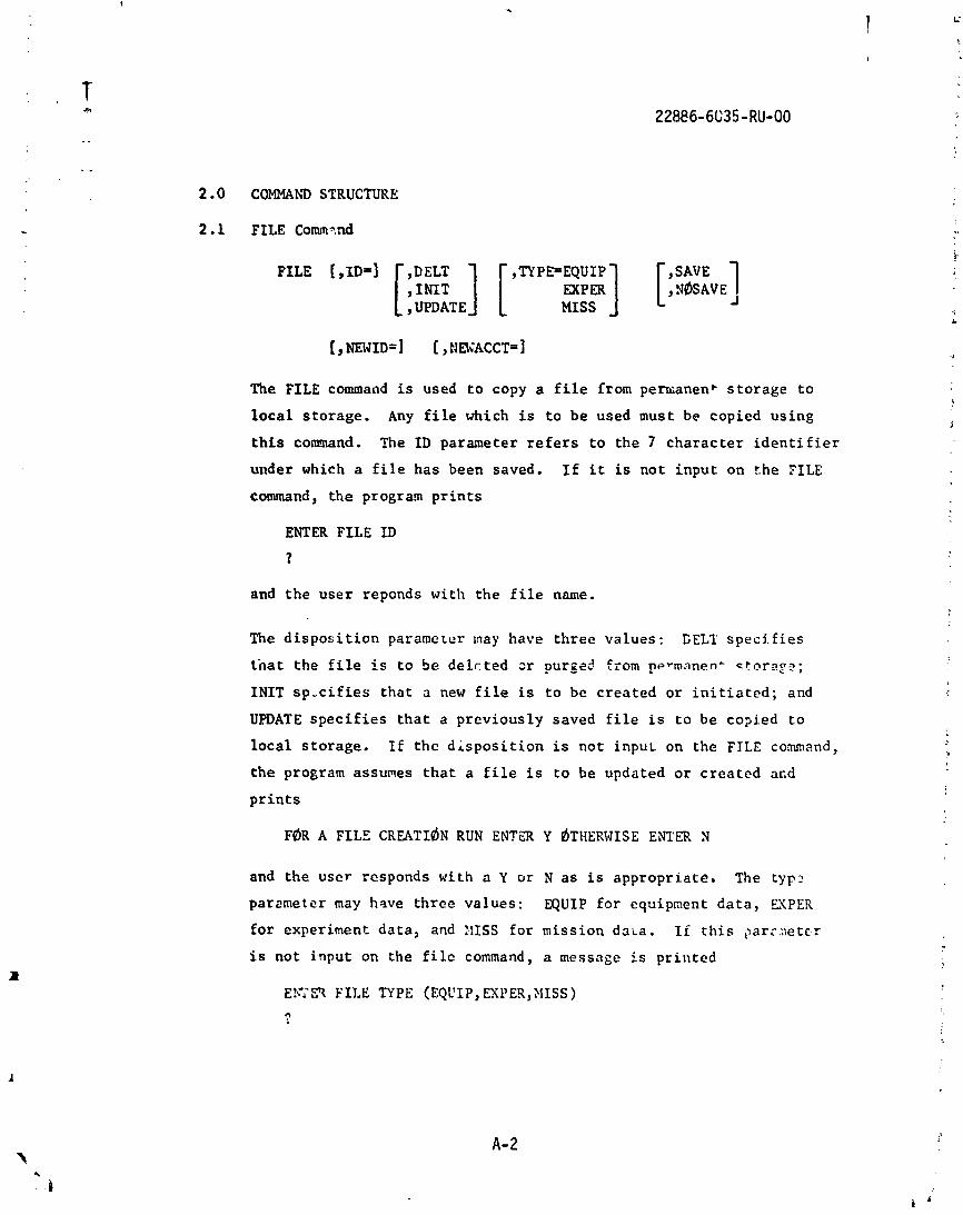
2.0 COMMAND STRUCTURE
2.1 FILE Comm3.nd
FILE [,ID=]
UPDATE
The FILE command i s used t o copy a f i l e from pemanent s torage t o
l o c a l s torage. Any f i l e which is t o be used must be copied using
t h i s comand. The I D parameter r e f e r s t o the 7 charac te r i d e n t i f i e r
under which a f i l e has been saved. I f i t is not input on the PILE
command, the program p r i n t s
ENTER FILE I D
?
and the user reponds with the f i l e name.
The d i s p o s i t i o n paramcrcr may have th ree values: GELT s p e c i f i e s
t h a t the file i s t o be delc ted sr purged from permanen+ storq?;
INIT s p - c i f i e s tha t a new f i l e i s t o be created o r i n i t i a t e d ; and
UPDATE s p e c i f i e s t h a t a previously saved f i l e i s t o be co?ied t o
l oca l s torage. I F the d i s p o s i t i o n i s not input on the FILE command,
the program assumes t h a t a f i l e i s t o be updated o r c rea ted arid
p r i n t s
F ~ R A FILE CREATI~N RUN ENTER Y ~ T H E R W I S E ENTER N
and the user rcsponds with a Y or N a s i s appropr ia te , The typ:!
parorneter may have three values: EQUIP f o r equipment da t a , MPER
fo r experiment- data , and ZiISS fo r mission d a ~ a . I f t h i s ,>ar:.netcr
i s not input on the f i l e command, a message is pr in ted
Eh*?Fl FILE TYPE (EQCIP, EXPER,ZIISS) 0
and the u s e r responds. The s a v e parameter has two va lues : SAVE
to r e t a i n a copy o f t h e new d a t a f i l e , and s ~ S A V E t o no t r e t a i n t h e
new d a t a f i l e . I f t h i r parameter is n o t i n p u t on t h e f i l e command,
a message is p r i n t e d
Td SAVE FILE E Y E R Y ~THERWISE ENL'ER N
and t h e u s e r responds wirh a Y o r N. If a f i l e is n o t to be changed
(it is t o be l i s t e d o r used t o g e n e r a t e p l o t s ) , then t h e r e is no
reason t o save i t . ?he p r e v i o u s l y saved v e r s i o n would remain i n
permanect stor::e. I f a f i l e is t o be changed and i t is d e s i r e d t o
s a v e i t under a d i f f e r e n t I D name, then t h e XEWID parameter must be
set . I f i t is n o t set, t h e program w i l l r e p l a c e t h e o l d f i l e wi th
the new d a t a . The NEJACCT is used t o save t h e new f i l e under someane
e l s e ' s account nuinbcr. This p a r a p e t e r i s used t o copy d a t a f i l e s
from ofie account t o ano ther . . - .
I n o r d e r f o r t h e prcgram t o t e s t whether t h e d a t a f i l e is t o be
szve?, it is ascessary to r e f e r e n c e i h e EDIT connand f o r t n a c i i i e .
Thus t o copy a d a t a f i l e from one account cumber t o ano ther , both
t h e FILE and EDIT ccmmands must be used.
EDIT Command
DIT [,ID=]
The ECIT command is : s e d t o change records i n a d a t a f i l e . The I D
parameter r e f e r s t o a 7 c h a r a c t e r f i l e name which is t h e same a s t h e
I D used i n the f i l e command. I f t h e I D is no t inpu t on t h e EDIT coin-
mand, t h e program p r i n t s
ENTER EDIT Ii)
?
and t h e u z e r e c t e r s t!12 r e c o r d nane. The program thcn p r i n t s
ENTER R E C ~ R D C ~ E P M N D (ADDR, CHGR,CWR,DLTR, LSTR, E:DR)
?
and t h e u s e r e n t e r s a record command. There are s ix record cocunarids:
ADDR,CHGR,CPYR,DLTR,LSTR, and E.WR. The form of t h e record ccmunand
is:
The I D parameter r e f e r s t o t h e 10 c 5 a r a c t e r name which un lque ly i d e n i -
f i e s each record i n a d a t a f i l e . I f i t is c o t i n p u t on t h e r e c o r d
command, t h e program p r i n t s :
and t h e u s e r responds a p p r o p r i a t e l y . The ?raLIST parameter is used t o
suppress t h e l i s t i n g o f t h e r e c o r d a t t h e end o f the record cormand.
I f i t is n o t i n p u t on t h e record command, t h e record w i l l be automa-
- t i c a l l y l i q t e d . T5e SEWID parameter a p p l i e s o n l y t o t h e CPI'R commacd
and w i l l be d i s c u s s e d l a t e r .
2 .2 . i ADDR Command
The command ADDR is used t o add a new record t o t h e d a t a f i l e .
2.2.2 CHGR Command
The CHGR command is used r o change o r modify t h e d a t a i n an e x i s t i n g
record . Therc a r e four modes c: o p e r a t i o n w i t h i n a CiiGR cmmand;
t h e s e e r e ADDN t o add d a t a p a i r s , RPLN t o r e p l a c e d a t a p a i r s , CELY
t o d e l e t e d a t a p a i r s , and E D M t o end t h e CHCR command processing.
The program p r i n t s :
and the u s e r responds. Depending on t h e type of d a t a f i l e and t h c
mode of change, the program w i l l p r i n t such r e q u e s t s a s :
Tb CHANGE TITLE ELTER Y dTHEliVISE EN'ER f3
?
EEJTER TITLE
?
d. CHAKGE WEIGHT E N E R Y 6THEXwISE ENTER N
?
ENTER WEIGHT
?
I@ CHAISE V ~ L U X E ENTER Y ~THERWISE ENTER N
?
EKTER V ~ L ~ R I E
?
ENT= (TIME,DATA VLUAE) PAIRS TERXINATILX; UlTH A $
?
ENTER DATA I?iDM(S) T d BE DELETED TEREIIXAT1:G WITH A $
The command CPYR is used t o copy a n e x i s t i n g record and change o r
modify and s t o r e i t under a new record ID. I f a new record is q u i t e
similbr t o a n e x i s t i n y one o r i t is desireci tc change 2 reccrd ZD,
the CA'R coaxnand is used. I f t he new record I D , NEWID, is not input
on t h e record c o ~ c m d , t he program p r i n t s
EWER NEW RECORD ID
?
and use r on t e r s the new record I D . Af t e r t h e record has been copied
t o t he new I D , the CHCR c o m a d l o g i c is en te red so t h a t t he new
record m y be changed. A t t he end of processing t h i s record coemnd
the program p r i n t s :
~d DELETE 0~ R E C ~ R D YS(.YXXY EX, ,R Y OTIIERKISE EhTiX N
and use r may d e l e t e o r pur&e the o l d d a t a record by e n t e r i n g '1.
2 .2 .4 DLTR Command
The DLTR record command is used t o d e l e t e o r purge a record.
2.2.5 LSTR Command
The LSTR record command is used t o l ist a s p e c i f i c record a t the
terminal.
2.2.6 ENDR Command
The ENDR record command is used t o te rmina te the EDIT process on a
f i l e . I t is a f t e r en t e r ing the ENDR conmand t h a t the f i l e w i l l be
sgved on permanent s torage. I f a l o t of e d i t i 3 g is t o b e c mt: t o ?
p a r t i c u l a r f i l e , i t i s a good idea t o use t h e E N R comm~nd t o terminate
t h e e d i t i n g and save t he f i l e every s o of ten . The EDIT command is then
r e inpu t and records commands continued. I n t h i s way n o t s o much typing
would have t o be rzdone t o r econs t ruc t t h e f i l e i f t h e terminal con-
nec t ion t o the conputer were l o s t .
2.3 LSTIDS Cominand .
The LSTIDS command is used t o list t h e record I D ' S o f a f i l e on the - t e r a i n s l . Thc ID parznctcr r e f e r s to the f i l e i d c n t i f i c r . I f i t i s
not i n p a t on the LSTIDS comand, t he program p r i n t s :
ENTER FILE I C
?
and the user responds. The record ID'S w i l l be i n a l p h a b e t i c a l o rder .
2.4 LSTF Comand
The LSTF command is used t o l i s t the complete d a t a f i l e . 'Ihe I D para-
meter r e f e r s t o the f i l e ID. I f i t is not input the program p r i n t s :
EhTER LSTF I D ?
and the u se r responds. The ~ F F L I N E parameter r e f e r s t o the equipxcnt
on which t o p r i n t the da ta . I f ~ F F L I X E i s spec i f i ed i t w i l l be prince2
on a p r i n t e r i n the computer opera t ions a rea . I f the ~ T F L I X E paramctcr
is not input , the prograt:I p r i n t s :
~b LIST ~ F F L I N E ENTER Y ~'TIIERWISE ENTER N
?
A- 6
and the user e n t e r s N f o r terminal p r i u t and Y f o r o f f l i n e p r i n t .
I f t he d a t a f i l e i s la rge , i t is d e s i r a b l e t o p r i n t i t on a high
speed p r i n t e r o f f l i n e .
2.5 P L ~ T Command
The P L ~ T command is used t o genera te Calcomp p l o t s from the i n f o r -
mation on the equipment, experiment, and mission d a t a f i l e s . Any
d a t a f i l e which i s necessary must be copied t o l o c a l s t o r age using
a FILZ comand. Four kinds of p l o t s a r e ava i l ab l e . If the p l o t
op t ion i s no t input on the PLQT command,,the program p r i n t s :
ENTER P L ~ T ~ P T I ~ N (BALL, MPP&!, MISP~W,P!IS ENG)
and the u se r responds. The BALL opt ion produces a b a l l c h a r t f o r
each subelement type showing which experiment conta ins what p icces of
equipment. FILE commands must have been used f o r equipment a d ex-
periment d a t a f i l e s . The EXPP~W opt ion produces a 3-D bar graph
p l o t with t i m e a s t he ho r i zon ta l va r i ab l e , equipment a s t he v e r t i c a l
va r i ab l e , and row2r a s the ba r va r i ab l e . The p l o t i s done f o r a
spec i f i ed experiment ID. I f che experiment I D is n c i input on the
PMT command, the program p r in t s :
ENTER EXPERIPIEhT I D
?
and the user responds. The user has the c a p a b i l i t y t o cba3ge the
t i m e axj.s when the program p r i n t s :
~0 CHANGE TIXE AYIS EhTER Y ~ T H E R I ~ I S E EZITER N
?
by en t e r ing Y i n which ca se the computer reques t s