Space Charge Neutralization in the ITER Negative Ion Beams Elizabeth Surrey Citation: AIP Conf. Proc. 925, 278 (2007); doi: 10.1063/1.2773666 View online: http://dx.doi.org/10.1063/1.2773666 View Table of Contents: http://proceedings.aip.org/dbt/dbt.jsp?KEY=APCPCS&Volume=925&Issue=1 Published by the American Institute of Physics. Related Articles Response to “Comment on ‘Interaction of two solitary waves in quantum electron-positron-ion plasma’” [Phys. Plasmas 18, 084701 (2011)] Phys. Plasmas 18, 084702 (2011) Determining the Bohm criterion in plasmas with two ion species Phys. Plasmas 18, 023505 (2011) Electrostatic ion waves in non-Maxwellian pair-ion plasmas Phys. Plasmas 17, 124501 (2010) Potential formation in front of an electron emitting electrode immersed in a plasma that contains a monoenergetic electron beam Phys. Plasmas 17, 083504 (2010) Double layer formation in a two-region electronegative plasma Phys. Plasmas 16, 122114 (2009) Additional information on AIP Conf. Proc. Journal Homepage: http://proceedings.aip.org/ Journal Information: http://proceedings.aip.org/about/about_the_proceedings Top downloads: http://proceedings.aip.org/dbt/most_downloaded.jsp?KEY=APCPCS Information for Authors: http://proceedings.aip.org/authors/information_for_authors Downloaded 07 Feb 2012 to 194.81.223.66. Redistribution subject to AIP license or copyright; see http://proceedings.aip.org/about/rights_permissions
Transcript
Space Charge Neutralization in the ITER Negative Ion BeamsElizabeth Surrey Citation: AIP Conf. Proc. 925, 278 (2007); doi: 10.1063/1.2773666 View online: http://dx.doi.org/10.1063/1.2773666 View Table of Contents: http://proceedings.aip.org/dbt/dbt.jsp?KEY=APCPCS&Volume=925&Issue=1 Published by the American Institute of Physics. Related ArticlesResponse to “Comment on ‘Interaction of two solitary waves in quantum electron-positron-ion plasma’” [Phys.Plasmas 18, 084701 (2011)] Phys. Plasmas 18, 084702 (2011) Determining the Bohm criterion in plasmas with two ion species Phys. Plasmas 18, 023505 (2011) Electrostatic ion waves in non-Maxwellian pair-ion plasmas Phys. Plasmas 17, 124501 (2010) Potential formation in front of an electron emitting electrode immersed in a plasma that contains a monoenergeticelectron beam Phys. Plasmas 17, 083504 (2010) Double layer formation in a two-region electronegative plasma Phys. Plasmas 16, 122114 (2009) Additional information on AIP Conf. Proc.Journal Homepage: http://proceedings.aip.org/ Journal Information: http://proceedings.aip.org/about/about_the_proceedings Top downloads: http://proceedings.aip.org/dbt/most_downloaded.jsp?KEY=APCPCS Information for Authors: http://proceedings.aip.org/authors/information_for_authors
Downloaded 07 Feb 2012 to 194.81.223.66. Redistribution subject to AIP license or copyright; see http://proceedings.aip.org/about/rights_permissions
Space Charge Neutralization in the ITER Negative Ion Beams
Elizabeth Surrey
EURATOM/UKAEA Fusion Association, Culham Science Centre, Abingdon, Oxfordshire, OX14 3DB, United Kingdom
Abstract. A model of the space charge neutralization of negative ion beams, developed from the model due to Holmes, is applied to the ITER heating and diagnostic beams. The Holmes model assumed that the plasma electron temperature was derived from the stripped electrons. This is shown to be incorrect for the ITER beams and the plasma electron temperature is obtained from the average creation energy upon ionization. The model shows that both ITER beams will be fully space charge compensated in the drift distance between the accelerator and the neutralizer. Inside the neutralizer, the plasma over compensates the space charge to the extent that a significant focusing force is predicted. At a certain position in the neutraliser this force balances the defocusing force due to the ions' transverse energy. Under these conditions the beam distribution function can change from Gaussian to Bennett and evidence of such a distribution observed in a multi-aperture, neutralized negative ion beam is presented.
Keywords: Space charge, neutralization, negative ion beam, ITER. PACS: 41.75Cn, 52.20Hv, 52.40MJ, 52.52-f 52.59Sa
INTRODUCTION
The presence of a space charge neutralizing plasma is a pre-requisite for any beam system that requires transport of the charged beam over significant distances. In the case of the two negative ion beams proposed for ITER - the lMeV D" heating beam (HNB) and the 100 keV H" diagnostic beam (DNB) - the three metre long neutralizer is preceded by a drift distance maintained at a pressure of approximately 0.015Pa [1]. This distance prevents the neutralizer gas entering the accelerating structure and hence reduces stripping losses. The length of this drift distance is 1.6 m in the HNB and 1 m in the DNB and without space charge neutralization the beam's own potential would significantly increase the effective beam divergence. Thus the assumption of space charge neutralization is a key aspect of the ITER design.
Space charge neutralization in negative ion beams is particularly interesting due to the possibility of achieving over-compensation. That is, the positive ion density at the beam axis exceeds the beam ion density and constitutes a distributed focusing force on the beam. Under this circumstance and providing that certain other conditions are satisfied, it is possible to obtain equilibrium of focusing and defocusing forces analogous to the self-pinch effect observed in electron beams [2].
A model is presented to calculate the ion and electron densities created by the beam on passing through the background gas and their effects on the space charge of the beam. The calculation extends into the neutraliser where the gas density rapidly
CP925, Production and Neutralization of Negative Ions and Beams, 1 f International Symposium, edited by M. P. Stockli
2007 American Institute of Physics 978-0-7354-0435-9/07/$23.00
278
Downloaded 07 Feb 2012 to 194.81.223.66. Redistribution subject to AIP license or copyright; see http://proceedings.aip.org/about/rights_permissions
increases and the effects of space charge neutralization are more acute. The circumstances necessary to fulfil the equilibrium condition are explored and the consequences for the beam distribution are discussed with reference to other negative ion systems.
SIMPLE M O D E L FOR NEGATIVE ION BEAM NEUTRALIZATION
Only two models of space charge neutralisation for negative ions are known from the literature, one due to Gabovich, etal. [3] and the other due to Holmes [4]. The present work is based on the Holmes model, as this is the most clearly derived of the two. However, some modification to the electron energy balance equation has been made as a result of an earlier model of the plasma generated in the neutraliser [5]. This modification will be discussed at length below.
The Source Terms
A negative ion beam passing through a background gas is subject to both electron stripping and ionization reactions that produce fast neutral and positively charged particles. Thus, in general, unless the background gas density is extremely low, a negative ion beam also contains neutral atoms, positive ions and electrons. All three of these particles can contribute to ionization of the background gas and hence to the space charge neutralisation. The presence of these other species would complicate the modelling significantly, so in this present work the modelling is restricted to the drift distance between the grounded accelerator electrode and the neutraliser and the first 250 mm of the neutraliser length. From the ITER Design Description Document [1] (ITER DDD), the line integrated target over this distance results in a negative ions loss of less than 10%, so that the beam can be considered to be wholly composed of negative ions without significant error.
The main interaction processes between the beam and the background gas are ionization:
A~+B° H>Af+B + +e and electron detachment
A~+B° H>A°+B°+e
-> A+ +B+ +e + e
where the underscore indicates a fast particle. There are additional reactions (such as ionization with dissociation) but the cross sections for these are at least an order of magnitude smaller than those for the two reactions above.
The fast electrons created by detachment have an energy given by:
279
Downloaded 07 Feb 2012 to 194.81.223.66. Redistribution subject to AIP license or copyright; see http://proceedings.aip.org/about/rights_permissions
u e = u b ^ m b
(1)
where Ub is the energy of the beam ions and nie and mb the electron mass and beam ion mass respectively. For the HNB Ue = 272eV and for the DNB, Ue = 54eV for
which the ionisation cross sections are ~6xl0"21m2 and ~lxl0"20m2 respectively, compared to the cross section for ionisation by the negative ion of ~7.6xl0"21m2
(HNB) and ~lxl0"20m2 (DNB). For the HNB it has been assumed that the ionisation cross section of a negative ion is equal to that of its positive counterpart. This is correct at high energies, where the plane-wave Born approximation is valid [6]. For deuterium the corresponding energy is ~3.6MeV, somewhat higher than the HNB. For the DNB it is assumed that the ionisation cross section of the negative ion is the same as for its neutral counterpart as reported for energies as low as 10 keV [7]. However, the two cross sections only vary by a factor of two, so the error is not significant. As the cross sections and velocities of the beam ions and stripped electrons are of similar orders of magnitude, it follows that their densities alone determine their relative contribution to ionization of the background gas. It has already been established that the stripped electrons constitute less than 10% of the beam number density; hence their contribution to ionization will be of this order and can be neglected.
The detached electrons continue coaxially with the beam ions unless they are thermalised by inelastic scattering. The inelastic scattering rate coefficient, Km, can be determined from an empirical fit [8] to the data of Hiskes and Karo [9] as:
Km = 2.4xl012 exp(- 28/Ue) (eVmV1) (2)
Inserting the values pertaining to the ITER beams (272 eV for the HNB and 54 eV for the DNB as calculated above) shows that the detached electrons lose less than 1 eV in the drift section before the neutraliser and are therefore not thermalised with the background plasma at this point. (It has been shown [5] that the stripped electrons are thermalised in the neutralizer of the DNB and contribute to the background plasma. However, this requires the full three metre length of the neutralizer to achieve, so does not apply to this study).
There is a third possible contribution to the source term from the plasma electrons themselves. The ionization process creates electrons with energies ranging from zero to some maximum value dependent upon the beam energy and target molecule. This is discussed in detail in the section below, where it is shown that the fraction of plasma electrons with sufficient energy to cause further ionization is -25%. A figure of merit, that enables the three source terms to be compared, is the product of density, cross section and velocity (nav) for each of the source particles (beam ion, stripped electron and plasma electron). The values of this product are given in Table 1, which clearly demonstrates the dominant nature of the beam driven process. Thus, to within an accuracy of 10%, the source terms for the ions and electrons can be represented by the sum of the beam ionization processes alone.
280
Downloaded 07 Feb 2012 to 194.81.223.66. Redistribution subject to AIP license or copyright; see http://proceedings.aip.org/about/rights_permissions
TABLE 1. Values of the Product nav for the Three Source Terms (s"1) Source Term HNB DNB Beam Ions 8.2 38 Stripped Electrons 0.6 1.7 Plasma Electrons O01 O01
The Continuity Equations
The derivation of the continuity equations is given in reference 3 and will not be repeated in detail here. The rate of production of plasma ions is:
—L = Nnba lVb (3) at
where a is the total cross section for the production of positive ions and N the background gas number density. This ion production rate is balanced by a radial ion flux and assuming the motion is free fall this gives the ion continuity equation as:
27irfdn1 (r)v, (p, r) = 27ipdp^ — (4) dt
where dnt(r) is the incremental ion density at radius r caused by ion production dnjdt at radius p and v; is the ion velocity inside the beam potential well of depth cp. It can be shown3 that the ion density is given by:
„ _ ^ N a ^ m f r , ,
2e[cp + kT1/4e]1/2
where T; is the ion temperature and r0 is a characteristic radius of the beam, here chosen to contain 90% of a gaussian distribution . Note that equation (5) shows that
when cp=0, the ion density is given by nt = nbNajvbr0/(kTj/2mj) and that the
denominator limits the degree to which cp can be negative to a value of one quarter of the ion thermal energy. This differs from the model of reference 2, which appears to allow much larger negative values. However, this cannot constitute a state of equilibrium as the ions would accumulate inside the negative potential well, reducing its depth until the equilibrium condition was obtained.
The plasma electron continuity equation can be expressed in a similar manner, and assuming that the electron energy distribution is Maxwellian (which is only approximately correct as Figure 1 implies that the electron energy distribution function might be expected to show slightly elevated densities over a range of higher energies), the probability of escape from the potential is included in terms of the Boltzmann equation, thus:
27ir0ne0 expi ~ e<^T J ̂ = 7ir02Nnbaevb (6)
281
Downloaded 07 Feb 2012 to 194.81.223.66. Redistribution subject to AIP license or copyright; see http://proceedings.aip.org/about/rights_permissions
where oe is the total cross section for electron production and Te is the plasma electron temperature and ve the electron velocity. Thus the electron density on beam axis is given by:
„ _ 2nbNaer0vb
veexj9(-ecp/kTe)
Each electron that leaves the well removes an energy 2kTe, so determination of the electron energy source term Ue is required to complete the energy balance equation:
7ir02nbNaevbUe = 27ir^2kTene0 gxp(-eq>/kTe) (8)
Combining equations (7) and (8) gives
Ue = 2kTe (9)
Holmes [3] assumed that the stripped electrons were thermalised with the plasma electrons and that this was the source of the electron energy. It has been shown that this is never the case for the HNB and does not occur within the first 0.75 m of the DNB, so at this point the Holmes model has been modified to use the average creation energy of the electrons as the energy source term Ue and this quantity is evaluated in the section below.
Determination of the Electron Energy Source Term
The electrons created by ionization of the background gas can be ejected from the parent molecule with a range of energies from zero up to the energy of the projectile particle less a fraction of the ionization potential of the parent. This is possible due to recoil of the target nucleus, which can impart additional momentum. Rudd, et al [6] have tabulated empirical fits to the electron energy differential cross sections derived from both experiment and theory for protons incident on a range of target gases. From the tabulated fitting parameters for protons on H2 at 500 keV (HNB) and 100 keV(DNB) the differential cross section da/dw for the production of an electron of energy w can be calculated. The average electron energy is then given by:
f w—dw — i dw w = ~l (10)
w"f da , — dw
o dw
Of particular interest is the fraction of these electrons possessing energies above the ionization potential, Ib of the parent molecule. These electrons can contribute to
282
Downloaded 07 Feb 2012 to 194.81.223.66. Redistribution subject to AIP license or copyright; see http://proceedings.aip.org/about/rights_permissions
further background ionization and hence to the source term. This fraction, f, and their
average energy wt are given by:
WT da , J —dw
f-dw
I da
dw dw
Wf
da , w—dw
dw
da
dw
(11)
dw
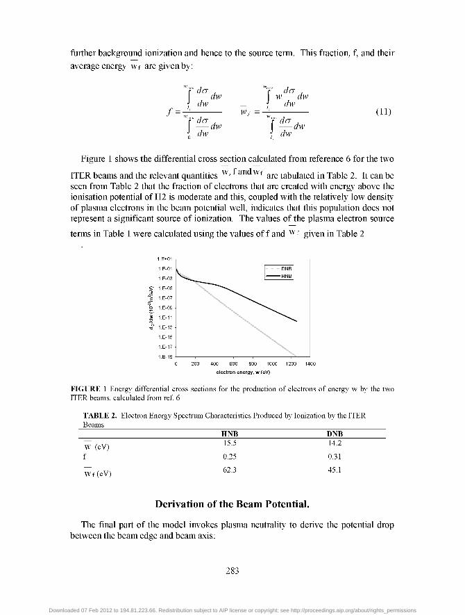
Figure 1 shows the differential cross section calculated from reference 6 for the two
ITER beams and the relevant quantities w ' a Wf are tabulated in Table 2. It can be seen from Table 2 that the fraction of electrons that are created with energy above the ionisation potential of H2 is moderate and this, coupled with the relatively low density of plasma electrons in the beam potential well, indicates that this population does not represent a significant source of ionization. The values of the plasma electron source
terms in Table 1 were calculated using the values of f and w f given in Table 2
200 400 600 800 1000
electron energy, w (eV)
1200 1400
FIGURE 1 Energy differential cross sections for the production of electrons of energy w by the two ITER beams, calculated from ref 6
TABLE 2. Electron Energy Spectrum Characteristics Produced by Ionization by the ITER Beams
HNB DNB
W (eV) f
W f (eV)
15.5
0.25
62.3
14.2
0.31
45.1
Derivation of the Beam Potential.
The final part of the model invokes plasma neutrality to derive the potential drop between the beam edge and beam axis:
283
Downloaded 07 Feb 2012 to 194.81.223.66. Redistribution subject to AIP license or copyright; see http://proceedings.aip.org/about/rights_permissions
nh +n„ (12)
Substituting from equations (5), (7) and (9) and simplifying gives the expression:
(13) 1 + 2r0Naevb r0Na1vbm1
1/2
ve exp(- ecp/kTe) V2e[cp + kT; /4e] 1/2
This can be solved numerically to give cp. Note that the reduced beam potential, cp/Te , does not depend on the beam density but only on the product Nr0. The
variation of reduced potential with this product is shown in Fig 2 for a non-specific 1 MeV D" beam. Although it is not clear from Fig. 2, the potential does become slightly negative forvalues of Nr0 less than 1015m"2.
1.E+14 1.E+15 1.E+16 1.E+17 1.E+18 1.E+1
Nr, (m 2)
1.0E+14 6.0E+16
Nr„ (nO
FIGURE 2 The reduced beam potential of a lMeV D" beam as a function of Nr0. An expanded view at low Nr0 is shown in the right hand figure.
APPLICATION TO THE ITER BEAMS
The ITER beams are composed of 1280 beamlets extracted from apertures arranged in rectangular blocks of 5x16, separated by 80 mm. The reference beamlet divergence is 5 mrad and simulations1 imply that the beam radius exiting the accelerating structure is ~4 mm. The aperture separation (centre-to-centre) is 20 mm and the beamlet from each aperture is slightly steered by offset aperture steering to a focal point at the exit of the residual ion dump approximately 7 m distant. In the vertical plane the beamlets converge at a plane in the ITER first wall, some 23.4 m distant. As a consequence of these steering angles and the beam divergence the beamlets begin to overlap inside the drift distance before the neutraliser. Given that the potential is dependent on the beam radius, it is necessary to define some characteristic beam radius that accounts for the beam overlap.
It is assumed that each beamlet has a Gaussian distribution characterised by a 5 mrad 1/e divergence, i.e. ignoring the halo adopted by the ITER DDD. By calculating the positions of each beamlet centroid at points along the drift distance and 250 mm
284
Downloaded 07 Feb 2012 to 194.81.223.66. Redistribution subject to AIP license or copyright; see http://proceedings.aip.org/about/rights_permissions
into the neutraliser it is possible to obtain the fraction, F, of the beamlet that overlaps its neighbour(s) from:
F(z) = Jer/>(-rV 2)ir (14) X
where 2X is the separation between two adjacent beamlet centroids at position z. The effect of overlapping beamlets can then be included as a modification of the
characteristic radius of a single beamlet that depends on the fraction F and the distance between the central beamlet and one at the edge of the beamlet array. Thus the characteristic radius, r0(z) is defined as:
r0(z)=rb(z) + F(z)AW(z) (15)
where rb(z) is the beamlet radius at a distance z from the grounded accelerator grid and AW(z) is the distance between the centroids of the central and extreme beamlets. Close to the accelerator where the beamlets do not overlap, r0=rb, the beamlet radius but further downstream r0 increases as the overlap fraction increases. Values of r0(z) were only determined for the horizontal array of five beamlets as this gives the smaller of the two characteristic radii. Similarly the current contained within the beamlet increases as the beamlets overlap. The effective current is defined to be:
Ieff(z) = Ib[l + F(z)] (16)
where lb is the beamlet current (31mA in the HNB and 46mA in the DNB). One consequence of overlapping beamlets is the formation of a potential well
where the beam potentials of two adjacent beamlets merge. A slow positive ion created at a radial position r in the potential of the first beamlet will be expelled with energy ec[)r and enter the potential of the second beamlet, where it will penetrate to a distance r from the beam axis. At this point the ion's energy will be reduced to zero and it will be expelled from the second beamlet potential back into the first. In this way the ion will oscillate between beamlets continuously unless it is subject to a collision.
In the drift distance the background gas pressure is approximately constant at 4.5xl018m"3 in the HNB and 2.5xl018m"3 in the DNB but in the neutraliser the pressure rises from the entrance to the centre. Thus for the final 250 mm of the calculation the gas pressure is assumed to rise linearly with the gradient defined by the central pressure and the pressure at the entrance of the neutraliser. Thus the product Nr0 in equation (13) is a function of z, the axial distance from the accelerator.
Figure 3 shows the values of reduced potential obtained for the HNB and DNB systems as a function of axial distance. The shorter drift distance in the DNB, coupled with the lower gas density for this system restricts the values of NrO that can be obtained. In the HNB, the reduced potential is approaching saturation with NrO and resembles Fig. 2. It can be seen that the potential is positive in both systems, indicating a degree of over compensation.
285
Downloaded 07 Feb 2012 to 194.81.223.66. Redistribution subject to AIP license or copyright; see http://proceedings.aip.org/about/rights_permissions
— HNB 3.00- —DNB
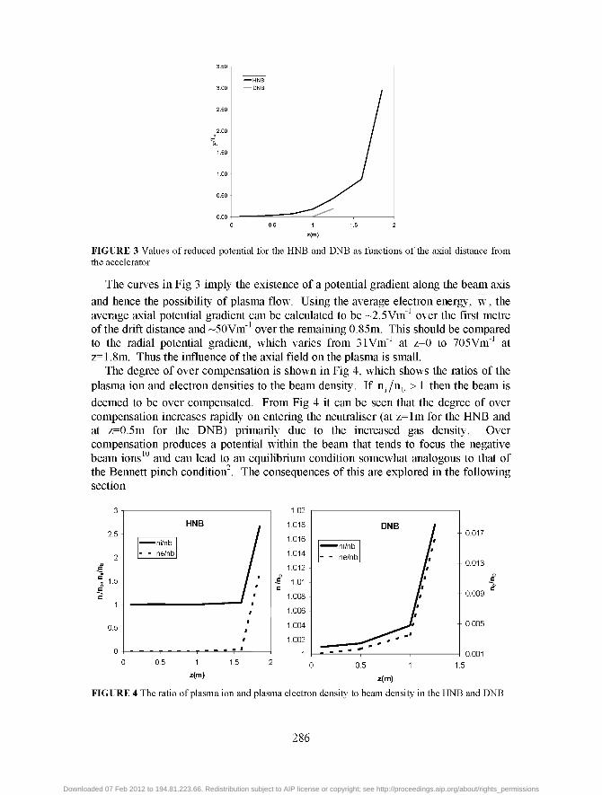
FIGURE 3 Values of reduced potential for the HNB and DNB as functions of the axial distance from the accelerator
The curves in Fig 3 imply the existence of a potential gradient along the beam axis and hence the possibility of plasma flow. Using the average electron energy, w, the average axial potential gradient can be calculated to be ~2.5Vm_1 over the first metre of the drift distance and ~50Vm_1 over the remaining 0.85m. This should be compared to the radial potential gradient, which varies from 31Vm_1 at z=0 to 705Vm_1 at z=1.8m. Thus the influence of the axial field on the plasma is small.
The degree of over compensation is shown in Fig 4, which shows the ratios of the plasma ion and electron densities to the beam density. If nj/nb > 1 then the beam is
deemed to be over compensated. From Fig 4 it can be seen that the degree of over compensation increases rapidly on entering the neutraliser (at z=lm for the HNB and at z=0.5m for the DNB) primarily due to the increased gas density. Over compensation produces a potential within the beam that tends to focus the negative beam ions10 and can lead to an equilibrium condition somewhat analogous to that of the Bennett pinch condition2. The consequences of this are explored in the following section
?5 -
2 -
1.5 -
0.5 -
n -
ni/nb - - ne/nb
T
HNB
- - T "
/ /
/ : / '
r i
i
i
_ - - f
0.5 1
z(m)
1.5
z(m)
0.017
0.013
-- 0.009
-- 0.005
0.001
FIGURE 4 The ratio of plasma ion and plasma electron density to beam density in the HNB and DNB
286
Downloaded 07 Feb 2012 to 194.81.223.66. Redistribution subject to AIP license or copyright; see http://proceedings.aip.org/about/rights_permissions
Effect of Over Compensation in Negative Ion Beams
It was first noted in ref 10 that overcompensation can lead to a distributed, electrostatic force acting to focus the beam. This force is given by:
F r = - e E r = - ^ ^ = - ^ (17) 2e0 27i60vbr
where a = (n: - nb )/nb is the degree of overcompensation expressed as a fraction of
the beam density. This is similar to the Bennett model [1], which describes the self consistent transverse equilibrium of an electron beam propagating through a plasma background. In this case the focusing force is produced by the self magnetic field of the electron beam, rather than the radial potential gradient of the background plasma. The key element, however is that in both cases the beam space charge is fully neutralized and that the focusing force balances the transverse velocity spread of the beam, characterized by a temperature, T. It is straightforward to show that the analogous expression for the equilibrium condition in the negative ion beam is:
kT = ^ L _ (18) 87T60Vb
The ion temperature, T, in the proposed ITER source is unknown but will probably be of the order 0.5eV to leV. Thus the equilibrium condition of equation (18) will be satisfied for over compensation of the order a~0.05 for the HNB and a~0.015 for the DNB. From Fig. 4 it can be seen that such values of a are readily achieved in the first 100 mm of the neutralizer for the HNB (and slightly further into the neutralizer for the DNB) and are exceeded at distances beyond. Under these conditions, the beam experiences a net focusing force that will compress it, increasing the value of T until the transverse velocity overcomes the compressive force.
One consequence of the equilibrium condition is that the beam distribution takes on the Bennett form:
[l + (r/0]
where r0 is a characteristic radius. This distribution is similar to a Gaussian at small radii but deviates from it at larger radii, being characterized by having a higher intensity at large radii than in the Gaussian. Reference 10 gives several examples of the observation of the Bennett distribution in an H" beam extracted from a single aperture propagating with a constant value of Nr0. The ITER beams do not fulfil this condition and furthermore, as the beam propagates further into the neutralizer, the fraction of neutral and positive particles increases. Both of these have a finite ionization cross section, so the background plasma production will continue but the value of potential and its effect on the negative ion component is unclear. Presumably, the distribution of the neutral beam exiting the neutralizer will be a
287
Downloaded 07 Feb 2012 to 194.81.223.66. Redistribution subject to AIP license or copyright; see http://proceedings.aip.org/about/rights_permissions
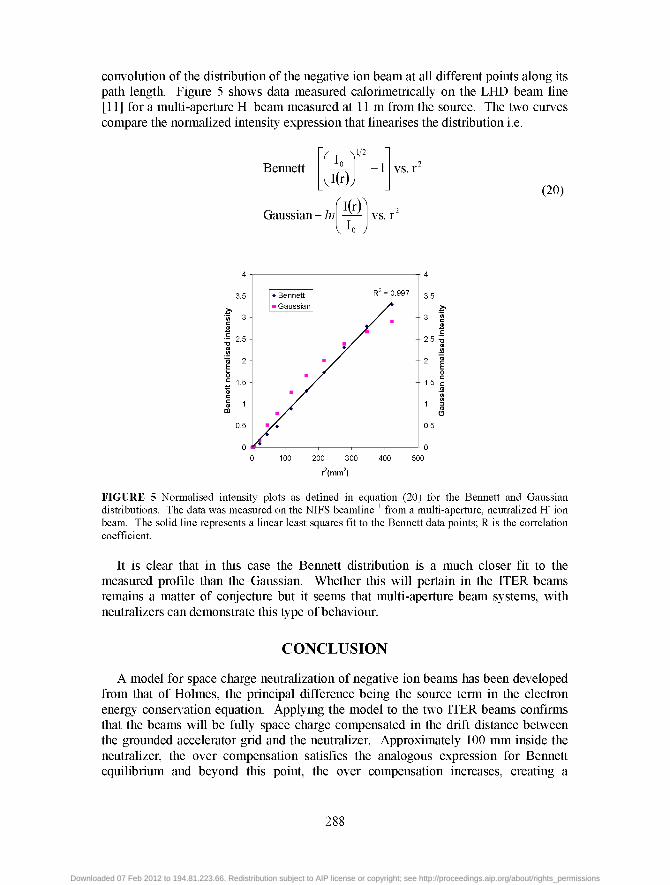
convolution of the distribution of the negative ion beam at all different points along its path length. Figure 5 shows data measured calorimetrically on the LHD beam line [11] for a multi-aperture H" beam measured at 11 m from the source. The two curves compare the normalized intensity expression that linearises the distribution i.e.
Bennett 2<L I(r)
1/2
vs. r
fif-W Gaussian- In vs. r
(20)
FIGURE 5 Normalised intensity plots as defined in equation (20) for the Bennett and Gaussian distributions. The data was measured on the NIFS beamline11 from a multi-aperture, neutralized H" ion beam. The solid line represents a linear least squares fit to the Bennett data points; R is the correlation coefficient.
It is clear that in this case the Bennett distribution is a much closer fit to the measured profile than the Gaussian. Whether this will pertain in the ITER beams remains a matter of conjecture but it seems that multi-aperture beam systems, with neutralizers can demonstrate this type of behaviour.
CONCLUSION
A model for space charge neutralization of negative ion beams has been developed from that of Holmes, the principal difference being the source term in the electron energy conservation equation. Applying the model to the two ITER beams confirms that the beams will be fully space charge compensated in the drift distance between the grounded accelerator grid and the neutralizer. Approximately 100 mm inside the neutralizer, the over compensation satisfies the analogous expression for Bennett equilibrium and beyond this point, the over compensation increases, creating a
288
Downloaded 07 Feb 2012 to 194.81.223.66. Redistribution subject to AIP license or copyright; see http://proceedings.aip.org/about/rights_permissions
distributed focusing force. It is not clear how the beam will respond to this and the changing ratio of negative, neutral and positive particles as the beam propagates further into the neutralizer. One consequence of the Bennett equilibrium is a change in the beam distribution. This has been observed before in single aperture beams and evidence is provided here that this distribution can occur in multi-aperture beam systems with a neutralizer.
ACKNOWLEDGEMENTS
The author would like to thank Dr A. J. T. Holmes of Marcham Scientific for helpful discussions during this work.
This work was funded jointly by the United Kingdom Engineering and Physical Sciences Research Council and by the European Communities under the contract of Association between EURATOM and UKAEA. The views and opinions expressed herein do not necessarily reflect those of the European Commission.
REFERENCES
1. ITER Design Description Document N53 DDD 29 01-07-03 R0.1, Neutral beam Heating and Current Drive (NBH & CD) System, IAEA (2003)
2. W. H. Bennett, Phys Rev 45, 890-897 (1934) 3. M. D. Gabovich, L. S. Simonenko ans I. A. Soloshenko, Sov. Phys. Tech. Phys. 23, 783-785 (1978) 4. A. J. T. Holmes, "Beam Transport" in The Physics and Technology of Ion Sources l" Edition, edited by I. G.
Brown, New York: John Wiley & Sons, 1989, pp86-88 5. E. Surrey, Nucl. Fusion Special Issue 46, S360-S368 (2006) 6. M. E. Rudd, Y-K. Kim, D. H. Madison & T. J. Gray, Rev. Mod. Phys 64, 441-490 (1992) 7. Ya. M. Fogel, A. G. Koval & Yu. Z. Levchenko, Sov. Phys. JETP, 11, 760-767(1960); ibid. 12, 384-391
(1961) 8. A. J. T. Holmes, Plasma Sources Sci. Technol. 5, 453-473 (1996) 9. J. R. Hiskes and A. M. Kara, Electron Energy Distributions, Vibrational Population Distributions UCRL
87779, USA: 10. E. Surrey and A. J. T. Holmes, "The Distribution Function in Space Charged Neutralized H" Ion Beams" in
Application of Accelerators in Research and Industry-1996, edited by J. L. Duggan and I. L. Morgan, AIP Conference Proceedings 392, American Institute of Physics, Woodbury, NY, 1997, ppl219-1222
11. Y. Takeiri, et a l , Rev. Sci. Instrum.67, 1021-1023 (1996)
289
Downloaded 07 Feb 2012 to 194.81.223.66. Redistribution subject to AIP license or copyright; see http://proceedings.aip.org/about/rights_permissions