33
Space Frame Structures Space Frame Structures for SNAP for SNAP Bruce C. Bigelow University of Michigan Department of Physics 11/04/04
| Date post: | 24-Dec-2015 |
| Category: |
Documents |
| Upload: | deborah-shaw |
| View: | 216 times |
| Download: | 0 times |
Space Frame Structures for SNAPSpace Frame Structures for SNAP
Bruce C. Bigelow
University of Michigan
Department of Physics
11/04/04

2
Space Frames for SNAPSpace Frames for SNAP
SNAP already has baseline primary and secondary structures. Why look at others?
Minimizing structure mass = mission flexibility Higher resonant frequencies are (almost) always better Minimizing carbon fiber mass reduces H2O dry-out issues
Open structures provide maximum access to payloads Space frame structures are prevalent in space (heritage)

3
Space FramesSpace Frames
Features: Loads carried axially (ideally) Joints/nodes carry some moments (not space truss) Deflections scale linearly with length:
d = PL/AE loads carried in tension/comp. (SF) Versus:
d = PL/nAG loads carried in shear (monocoque) d = PL^3/nEI loads carried in bending
Fast and easy to model with FEA Facilitate test and integration Space frames are ideal for supporting discrete loads Space frames make poor fuel tanks and fuselages…

4
Space Frames for SNAPSpace Frames for SNAP
Status of space frames for SNAP(PPT presentations in BSCW PS1300/Weekly):
Space frame spectrograph mount 05/14/04 Athermal (constant length) strut designs 06/04/04 Det. space frame designs for TMA-63 07/29/04 Indet. Space frame designs for TMA-65 08/26/04 Node/joint design concepts 09/02/04 Survey of space heritage structures 09/02/04 Minimum obscuration SMA structure 09/16/04 TMA 65, fold mirror, and lower baffle 10/28/04

5
Spectrograph mountSpectrograph mount
Design features: Hexapod space frame to carry 10Kg spectrograph 2:1 hexapod geometry => horizontal deflections, no tilts Attaches to common focal plane mounting points
Essentially no loads carried by focal plane assembly Simple interface to spectrograph
3 discrete support points, or round flange Supports spectrograph load near center of mass
Minimizes moment loads Simple interface to FP (mount points, cylindrical volumes) Spectrograph and mount easily separate from FPA Invar, CF, or athermal struts
Simple control of spectrograph thermal defocus

6
FEA ModelFEA Model
SNAP Baseline design:
• Moly, Invar, Ti flexures
• Attaches to FPA baseplate
• Loads carried near detect.
Natural frequencies for spectrograph, mount, and flexures: 116, 121, 164 Hz.
Mass: ?

7
Spectrograph mounting structureSpectrograph mounting structure
Ease of access to detector connectionsFP assembly with spectrograph included (note redundant str.)

8
Dynamic FEADynamic FEA
f1 = 413 Hz, transverse mode, 25 x 2 mm Invar struts, 2.5 Kg, f1 = 675 Hz for carbon fiber (MJ55), 25 x 2 mm struts, 0.5Kg
First 6 freq:
1. 413 Hz
2. 415 Hz
3. 416 Hz
4. 470 Hz
5. 478 Hz
6. 490 Hz

9
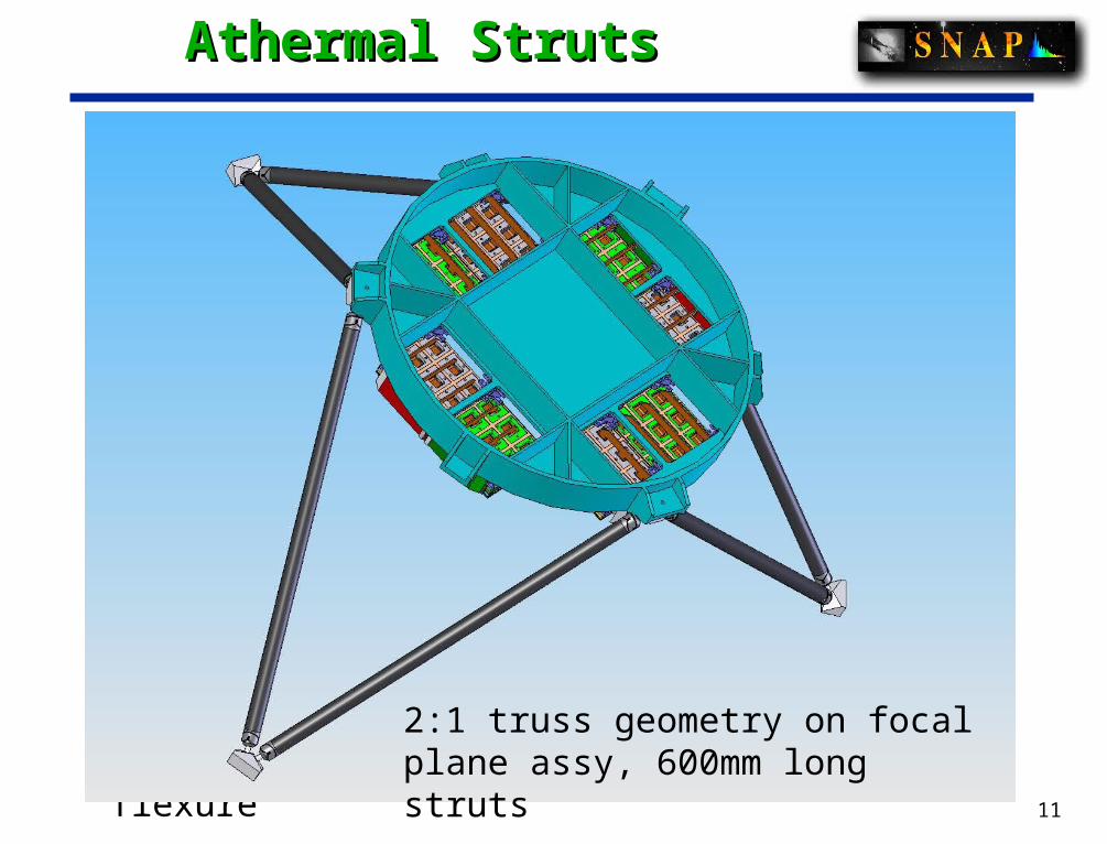
Athermal StrutsAthermal Struts
Design features: Thermally compensated or controlled length struts 3 materials to provide varying expansion/contraction Avoid high stresses due to CTE mismatches Provide integral flexures for kinematic constraints Provide features for length adjustments (alignment) Application details required for FEA

10
Athermal StrutsAthermal Struts
Blue = Ti CP Grade 1 --- 17 PPM/K
Light Grey = Invar --- 1.26 PPM/K
Dark Grey = Ti 6Al 4V --- 6.7 PPM/K
L1 = 156mm, L2 = 78mm, L3 =222mm(x2), 600mm long strut
11
Athermal StrutsAthermal Struts
EDM cross-flexure2:1 truss geometry on focal plane assy, 600mm long struts

12
OTA Space FramesOTA Space Frames
Motivations: Minimize telescope structure deflections under gravity Maximize resonant frequencies on ground and in orbit Minimize structure mass, CF outgassing, etc. Maximum access to optical elements (assembly, test) Explore parameter space for SNAP structure

13
OTA Space Frames – TMA 63OTA Space Frames – TMA 63
Design objectives: Maintain symmetry to extent possible Locate nodes for access to primary loads
3 nodes above secondary mirror for hexapod mount 3 nodes above primary for secondary support 3 nodes behind primary for mirror, attach to SC 3 nodes below tertiary axis to stabilize secondary supp.
Locate nodes and struts to avoid optical path Size struts to minimize mass and deflections Round struts used for constant stiffness vs. orientation Non-tapered struts used – easy for first cut designs COI M55J carbon fiber composite used for all struts CF can be optimized for cross section, thermal expansion

14
OTA Space Frames – TMA 63OTA Space Frames – TMA 63

15
TMA-63 structure FEATMA-63 structure FEA
Elements

16
Dynamic FEADynamic FEA
Dynamic analyses: Telescope mass: 360kg payload, 96kg structures Modal analysis for ground, launch
f1 = 72 Hz f2 = 74 Hz f3 = 107 Hz f4 = 114 Hz f5 = 131 Hz
Modal analysis for on-orbit (unconstrained) f7 = 106 Hz f8 = 107 Hz

17
Static FEAStatic FEA
First ground mode, 72 Hz

18
Nodes for space framesNodes for space frames
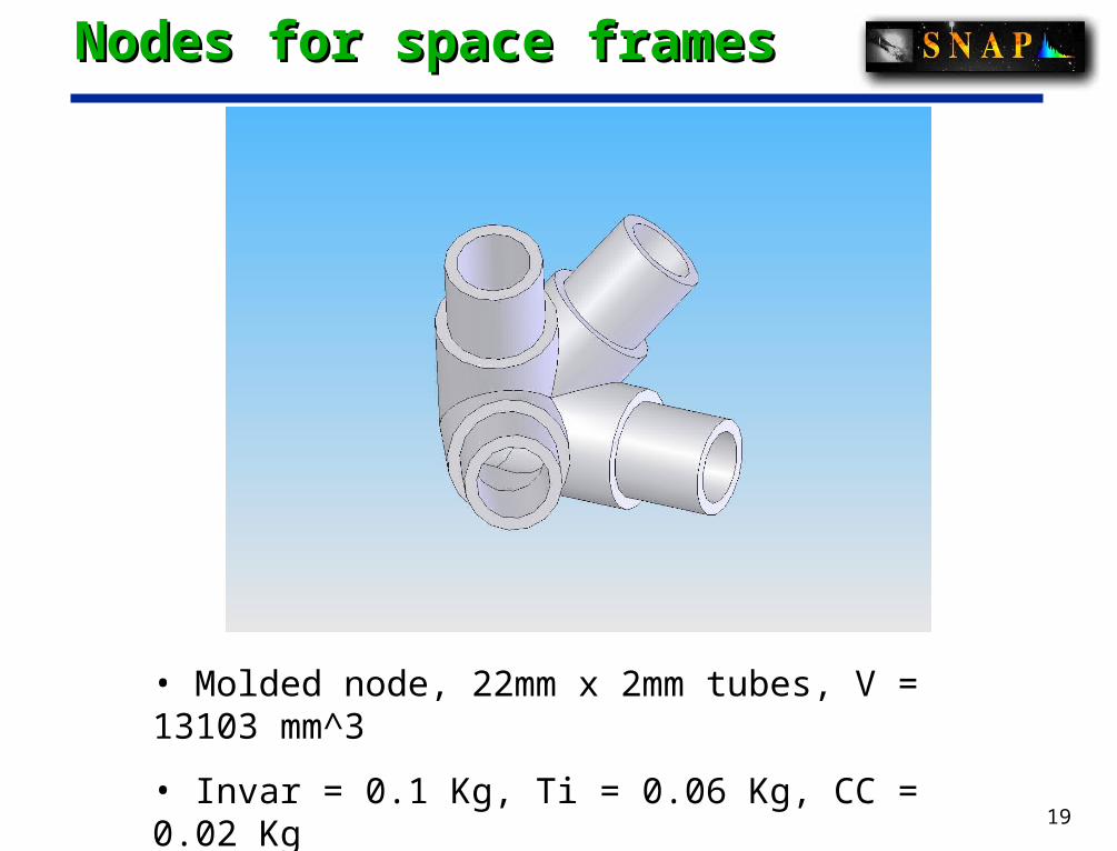
Design features: Nodes connect the struts in a space frame Accommodate diameters of struts (constant diameter, wall) Minimize mass (often a large fraction of the mass in a SF) Maximize ease of fabrication and assembly Provide attachment points for secondary structures
19
Nodes for space framesNodes for space frames
• Molded node, 22mm x 2mm tubes, V = 13103 mm^3
• Invar = 0.1 Kg, Ti = 0.06 Kg, CC = 0.02 Kg

20
Nodes for space framesNodes for space frames
• Machined node, 22mm OD tubes, V = 58561 mm^3
• Invar = .47 Kg, Ti = 0.26 Kg, CC = 0.09 Kg

21
Secondary Mirror StructureSecondary Mirror Structure
Design features: Minimize pupil obscuration by SMA structures Minimize structure mass Maintain high first resonance Secondary support vanes:
25 mm diameter x 2 mm wall Requires revisions to current outer baffle design

22
Secondary StructureSecondary Structure
Blue/green hexapod struts are outside of CA

23
Secondary StructureSecondary Structure
Trial 9, ring at 2.85m elev.

24
Space frame developmentsSpace frame developments
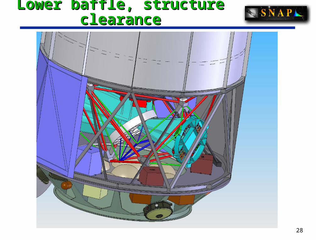
Latest work: TMA 65 structure with nodes Fold mirror sub-frame Lower baffle structure (Al) and close-outs
Rings have 50 x 50 x 3 mm sections Struts have 50 x 50 x 6mm sections Upper baffle mass = 190 Kg Baffle structure (38 Kg) + close-outs (27 Kg) = 65 Kg f1 = 33 Hz CF baffle structure: 20Kg, 40Hz

25
TMA-65 structure with nodesTMA-65 structure with nodes

26
Fold mirror sub-structureFold mirror sub-structure

27
Lower baffle structureLower baffle structure
28
Lower baffle, structure clearanceLower baffle, structure clearance

29
Deformation in 1g held by GSEDeformation in 1g held by GSE(baffle displacement~2.6mm)(baffle displacement~2.6mm)
Baseline: mass = 79 Kg

30
Lower baffle structureLower baffle structure
mass = 65 Kg

31
Baffle/OTA Assembly Mode 1, 20HzBaffle/OTA Assembly Mode 1, 20Hz

32
Lower baffle structureLower baffle structure

33
Space frames for SNAPSpace frames for SNAP
Conclusions: Space frames are applicable to most SNAP structures Space frame structures offer significant mass reductions over
current baseline designs Space frame structures provide higher frequencies/mass
compared to baseline designs Space craft structure heritage is well established Space frame structures will readily scale to larger apertures Space frames for SNAP: Ready for prime time!


