25
Space Frequency Coordination Group (SFCG) Database User’s Guide November 18, 2008 Contributed to the SFCG by NASA Prepared by ITT Industries

Space Frequency Coordination Group (SFCG) Database
User’s Guide November 18, 2008
Contributed to the SFCG by NASA
Prepared by ITT Industries

2
Table of Contents
Introduction……………………………………………………………………………... 4 Description……………………………………………………………………………… 4
System Requirements……………………………………………………………….. 5 Security……………………………………………………………………………... 5 Design………………………………………………………………………………. 5 What’s New…………………………………………………………………………. 5
Step-by-Step Instructions……………………………………………………………….. 6 Access………………………………………………………………………………. 6 Home Page………………………………………………………………………….. 7 Enter Data…………………………………………………………………………... 7
Overview of Parameters………………………………………………………… 7 General Form Instructions……………………………………………………… 10 RF Carrier Action Form………………………………………………………… 10 RF Carrier Definition Form…………………………………………………….. 13 Terminal Assignment Form…………………………………………………….. 16 Ground Terminal Definition Form……………………………………………… 17 Space Terminal Definition Form……………………………………………….. 17
Generate a Report…………………………………………………………………… 22 General Instructions…………………………………………………………….. 22 Summary Report………………………………………………………………... 23 Detailed Reports………………………………………………………………… 24

3
Introduction The existing spacecraft and ground station database with a web interface was provided by NASA to the Space Frequency Coordination Group (SFCG) community in 2001. An action was assigned at the next meeting leading to the addition of sensor data to the database in 2002. Ongoing updates, additions, and modifications have been made to the database and web interface as requested following its initial deployment. In 2003, all data from a previous database incarnation was ported to the web interface version in 2003. It was hoped that this would spur more utilization. Usage increased slightly but the interface was still not widely used amongst the members.
As part of SFCG Action Item 23/8, NASA recently developed a spreadsheet “database” to collect and maintain S-Band mission data. Similarly, ESA developed an Excel file to hold all X-Band mission data. It seemed an unnecessary duplication of effort to expect members to both enter data into the online database and provide input to the maintainers of the spreadsheet “databases”. Additionally, it was noted at SFCG-24 in SFCG Action Item 24-4-1 that “The SFCG satellite database would be improved with a simplified interface for data entry and retrieval, flexibility in user output formats that include system overview information, the addition of a capability for including parameters for optical systems, and expanding the contents to include parameters from all member agency systems. Some assignments stemming from the action item are as follows:
1. Identify a simplified set of system parameters to use to characterize missions in the
SFCG satellite database. 2. Design and implement a new simplified web interface for the SFCG satellite database. 3. Investigate the feasibility of importing the X-band and S-band MS Excel databases into
the new SFCG satellite database. The first step in redesigning the database and web interface was to re-evaluate and simplify the list of requested parameters. The SFCG S-band and X-band spreadsheets were used as a first draft. Only a few modifications were made from this list. The number of requested parameters is significantly reduced from the existing database. The simplified interface design is described in detail in this document.
Description This section contains a brief description of the revised database and interface, highlighting areas where this version differs from its predecessor. As discussed in the previous section, the database provides SFCG members with the ability to enter data for data links affiliated with their agency. NASA has been responsive to SFCG requests in the design and now in the

4
simplification of the data entry and presentation. The database contents can be viewed by member agencies through spreadsheets designed to look like those familiar to the members.
System Requirements In order to utilize the web site, client will use a standard browser; IE is recommended, with Java Script enabled. This will allow users to enter data into the database. Additionally, users must have Microsoft Excel on their computer in order to view the database contents.
Security The web site requires an account for access. Accounts are available to participating member agencies. Users of the SFCG database will be required to provide a User Name and Password to enter the site. The access account record stores basic contact information about user, as well as, permission information in reference to website functionality and agency membership. Additionally, if an agency lead would like to assign “read-only” privileges to a user, then the agency lead need only include this designation in the request for a new user or ask for a re-designation of a current user.
Design The web interface was designed to allow users to step through a few simple forms to enter data for a particular RF Carrier. The databased information is presented to the user using Microsoft’s Excel spreadsheets. The files can be viewed via the browser or saved on the user’s system. The underlying structure holding the data is Microsoft’s SQL Server relational database. Database triggers and checks enforce the integrity of the data as it is entered, updated, or deleted. The web interface utilized JavaScript as a tool to perform some client-side checking and control entry flow; therefore users must have JavaScript enabled on their browser to use the website.
What’s New The simplified interface has a number of differences from the existing interface. The biggest change in the database is that the structure is now “RF Carrier centric” instead of being “mission centric”. This means that a user defines the information associated with the RF carrier for a spacecraft and assigns the terminal locations as the end points of each link associated with the RF carrier. Terminal locations can be Relay satellites (Forward and Return) or Ground Stations (Space to Ground and Ground to Space). An RF carrier definition may have one or more link terminals assigned to it. This approach eliminates the need for the work flow technique used in the earlier version. Previously, the image-mapped workflow aided the user to define the (1) Mission, (2) Mission Specific Satellite and Ground Stations, (3) Shared Relays and Ground Stations, and (4) Links. With the focus on each RF carrier, the hierarchy required in the workflow is no longer necessary. The RF carrier is the now the primary element in the SFCG database. This one change greatly simplifies the presentation of the forms and data sheets to the user.

5
Another significant modification in the new design is the abandonment of the mirrored database system. In the previous design the database was really two separate identically structured databases. One was for data as it was being entered and awaiting approval and the other housed the approved, “official” data. Access to data in the entry database was restricted based on agency, only allowing users of the owner agency to view the mission data until it was approved and published to the official database. The added complexity of this feature is not necessary in the new version since the RF carrier-centric approach will allow users to quickly enter data for a specific RF carrier and not have to collect all of the information for a particular mission before the data is complete and ready for approval.
Step-by-Step Instructions The following section describes the details for using the SFCG database. Screen shots are displayed as they appear in IE. An image is included for each form. A complete list of parameter options and/or value limits is provided, where applicable.
Access Users may access the database via the SFCG web site. This approach should be discussed with you SFCG representative. Access is also available directly via the URL, http://cnts.gsfc.nasa.gov/sfcg. As discussed earlier, entry to the website requires account parameters. After linking from the SFCG page or typing the URL in the browser, the security login panel is displayed as shown in Figure 1.
Figure 1: Account Login Panel
By providing the account information, the user is identified and is granted appropriate permissions and access to the site. The user should enter the User Name and Password in the box and click “OK”. Note: It is never a good practice to check the “Remember my password”

6
option. This circumvents the benefits of the password authentication if anyone accessing ones computer also has access to restricted password protected operations. Correctly entering information for an active account will allow a user to proceed to the site home page.
Home Page The home page is presented in Figure 2. This is the switchboard into database operations. As seen in the figure, the user can perform one of three operations from this page: (1) Enter Data, (2) Generate a Report, and (3) access Help. Clicking on any of these links brings up a separate operations window.
Figure 2: The SFCG Home Page
Enter Data
7
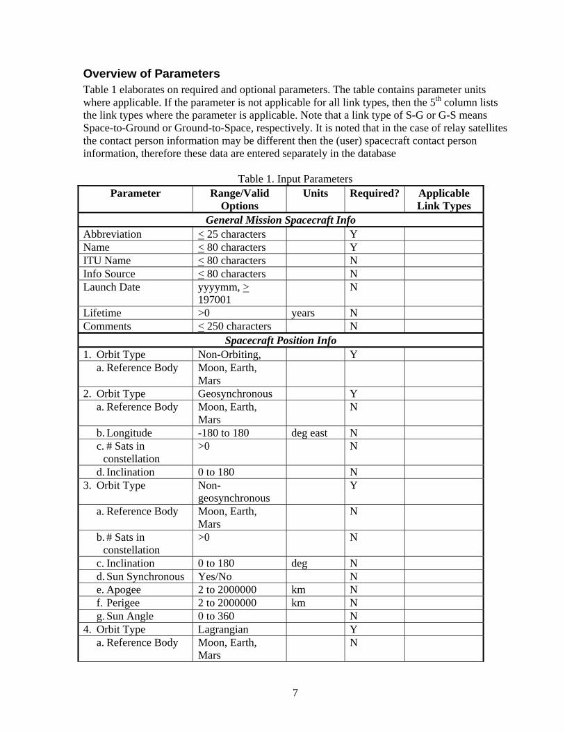
Overview of Parameters Table 1 elaborates on required and optional parameters. The table contains parameter units where applicable. If the parameter is not applicable for all link types, then the 5th column lists the link types where the parameter is applicable. Note that a link type of S-G or G-S means Space-to-Ground or Ground-to-Space, respectively. It is noted that in the case of relay satellites the contact person information may be different then the (user) spacecraft contact person information, therefore these data are entered separately in the database
Table 1. Input Parameters Parameter Range/Valid
Options Units Required? Applicable
Link Types General Mission Spacecraft Info
Abbreviation < 25 characters Y Name < 80 characters Y ITU Name < 80 characters N Info Source < 80 characters N Launch Date yyyymm, >
197001 N
Lifetime >0 years N Comments < 250 characters N
Spacecraft Position Info 1. Orbit Type Non-Orbiting, Y
a. Reference Body Moon, Earth, Mars
2. Orbit Type Geosynchronous Y a. Reference Body Moon, Earth,
Mars N
b. Longitude -180 to 180 deg east N c. # Sats in
constellation >0 N
d. Inclination 0 to 180 N 3. Orbit Type Non-
geosynchronous Y
a. Reference Body Moon, Earth, Mars
N
b. # Sats in constellation
>0 N
c. Inclination 0 to 180 deg N d. Sun Synchronous Yes/No N e. Apogee 2 to 2000000 km N f. Perigee 2 to 2000000 km N g. Sun Angle 0 to 360 N
4. Orbit Type Lagrangian Y a. Reference Body Moon, Earth,
Mars N

8
b. Lagrange Point L1, L2, L3, L4, L5
N
c. X Amplitude km N d. Y Amplitude km N e. Z Amplitude km N f. X Phase deg N g. Y Phase deg N h. Z Phase deg N
5. Orbit Type Deep Space Y a. Deep Space
Mission Type Orbiter, Fly-by, Lander/Probe, Body trailing, Body leading
N
b. Deep Space Body 25 characters N RF Carrier Info
RF Carrier Name 30 characters Y Carrier frequency 1 to 3000000 MHz N Bandwidth 0 to 1000 MHz N Max gain -3 to 100 dBi N Broadcast? Yes, No N Noise Temperature >0 K N G-to-S,
Forward Max Power -30 to 50 dBW N S-to-G, Return Max Spectral Density dBW/Hz N S-to-G, Return Modulation Type BPSK
QPSK DQPSK O/SQPSK 8PSK PCM/PM PCM/PSK/PM PCM/PM + PCM/PSK/PM Other
N
Coding < 80 characters Data Rate >0 Mbps N Symbol Rate >0 Msps N Other Carrier Info < 250 characters N Last Modified Automatic Automatic
Spacecraft Contact Person Info Name < 50 characters Y Address < 50 characters N Email < 40 characters Y Phone < 20 characters N Comments < 250 characters N

9
Ground Station General Info / General Relay Spacecraft Info Abbreviation < 25 characters Y Name < 80 characters Y Info Source < 80 characters N Return,
Forward Launch Date yyyymm N Return,
Forward Lifetime >0 years N Return,
Forward Comments < 250 characters N
Ground Station Position Info / Relay Spacecraft Position Info Latitude -90 to 90 deg N S-to-G, G-to-S Longitude -180 to 180 deg east N S-to-G, G-to-S Reference Body Moon, Earth,
Mars N Return,
Forward Longitude -180 to 180 deg east N Return,
Forward # Sats in constellation >0 N Return,
Forward Inclination 0 to 180 N Return,
Forward Ground Station Link Info / Relay Spacecraft Link info
Max Power -30 to 50 dBW N G-to-S, Forward
Max Spectral Density >0 dBW/Hz N G-to-S, Forward
Max Gain -3 to 100 dBi N S-to-G, Return Noise Temperature >0 K N S-to-G, Return
Relay Spacecraft Contact Person Info Name < 50 characters Y Return,
Forward Address < 50 characters N Return,
Forward Email < 40 characters Y Return,
Forward Phone < 20 characters N Return,
Forward Comments < 250 characters N Return,
Forward
General Form Instructions There are a few basic instructions that users should adhere to in completing the online forms. Firstly, users should avoid using the browser navigation controls while entering data. The

10
buttons on the forms should be used to control flow between data forms. Therefore, the user should never use the browser Forward or Back options. Secondly, the red asterisks (*) on the forms indicates that these parameters are required in order to proceed. Obviously, the more data the user is able to provide the more useful the database is to others trying to perform interference studies and sharing scenarios. As users step through the entry forms, they are prompted to define the mission spacecraft and RF carrier information and then information for each designated link terminal for the RF carrier. Some parameters in the database may have hard and/or soft limits imposed on them. Checking is performed upon submitting the forms to ensure that limits are adhered to. Table 1 indicates these limits. If the application detects any errors during the entry process, the user will not be allowed to continue. Alerts may appear to the user in two ways. An information alert dialog is used to notify the user when required fields are not supplied or parameters are not within set limits. In some cases the user may provide acceptable information but it is invalid because it would duplicate another entry in the database. Data should be reviewed as each entry form is completed. Updates are made to the database as each form is submitted throughout the entry process. When the terminals are added to complete the link of the RF Carrier, the user is given the option to view the data for the information just added.
RF Carrier Action Form The starting point for data entry is the form shown in Figure 3. Each person is assigned to an agency in the security database. The agency of the user is shown on the forms. This parameter is often used as a filter in querying the database. For instance, the RF Carrier selection box at the bottom of the form is populated with RF carriers assigned to the agency of the user for the selected link type.

11
Figure 3: RF Carrier Action Form
The user is presented with four types of links as shown in Table 2. The table provides descriptions of each link type. A link is defined from a mission spacecraft to a terminal. The terminal may be a relay spacecraft or a ground station. An RF carrier is one or more links sharing the same communications parameters assigned to designated terminal location(s). The RF carrier definition is associated with the mission spacecraft.
Table 2: Descriptions of Link Types Link Type Description
Forward A link in which a relay satellite transmits to a receiving mission spacecraft. Note that this link is only defining the space portion; it is not concerned with whether or not the relay satellite is responding to a transmission from the Ground.
Return A link in which a mission spacecraft transmits to a receiving relay satellite. Note that this link is only defining the space portion, it is not concerned with whether or not the relay satellite also transmitting to the Ground.
Space-to-Ground A link in which a mission spacecraft transmits a signal to a ground station.
Ground-to-Space A link in which a ground station transmits a signal to a mission spacecraft.

12
As seen in Figure 3, there are four functions available to the user for an RF Carrier: “Create New RF Carrier”, “Edit RF Carrier”, “Copy RF Carrier”, and “Delete RF Carrier”.
Create New RF Carrier To create a new RF Carrier, the user simply selects the link type from the option list and clicks the radio button “Create New RF Carrier”, followed by clicking the “Continue” button. These actions will present the user with a blank RF Carrier Definition Form. This form will be described in detail later in this section.
Edit RF Carrier To edit an existing RF Carrier, the user simply selects the link type from the option list and clicks the radio button “Edit RF Carrier”. Notice the option list labeled “RF Carrier” just above the continue button. This list has been populated with RF carriers from the database corresponding to the user’s agency and specified link type. The filtering of the RF carriers will make it easier to find the desired description. Using the arrow to display the list, make the desired selection. RF carrier names are only forced to be unique for a particular mission. Therefore, for clarity, the RF carrier description presented is a concatenation of the mission spacecraft and the RF carrier name. After selecting the RF carrier, proceed by clicking the “Continue” button at the bottom of the form. These actions will present the user with a RF Carrier Definition Form containing the databased parameters for the selected link.
Copy RF Carrier To copy an existing RF carrier, the user simply selects the link type from the option list and clicks the radio button “Copy RF Carrier”. Notice the option list labeled “RF Carrier” just above the continue button. This list has been populated with RF carriers from the database corresponding to the user’s agency and specified link type. The filtering of the links will make it easier to find the desired description. Using the arrow to display the list, make the desired selection. RF carrier names are only forced to be unique for a particular mission. Therefore, for clarity, the RF carrier description presented is a concatenation of the mission spacecraft and the RF carrier name. After selecting the RF carrier, proceed by clicking the “Continue” button at the bottom of the form. These actions will present the user with a RF Carrier Definition Form containing the databased parameters for the RF carrier to be copied.
Delete RF Carrier To delete an existing RF carrier, the user selects the link type from the option list and clicks the radio button “Delete RF Carrier”. The option list labeled “RF Carrier” just above the continue button is populated with RF carriers from the database corresponding to the user’s agency and specified link type. The filtering of the links will make it easier to find the desired description. Using the arrow to display the list, make the desired selection. RF carrier names are only forced to be unique for a particular mission. Therefore, for clarity, the RF carrier description
13
presented is a concatenation of the mission spacecraft and the RF carrier name. After selecting the RF carrier, proceed by clicking the “Continue” button at the bottom of the form. The user is presented with a request for confirmation of the RF carrier delete. With affirmation of the action the RF carrier is deleted from the database.
RF Carrier Definition Form The RF carrier definition form has four basic entry sections: the mission spacecraft general information, the mission spacecraft position information, information about the contact person associated with the mission spacecraft, and the RF carrier information. At the top of the form, the user’s agency and selected link type are presented. An example of the form is displayed in Figure 4.

14
Figure 4: RF Carrier Definition Form
Mission Spacecraft General Information This portion of the form contains the general information describing the mission spacecraft as shown in Figure 4. A user must select from the option list of spacecraft in the database or select “Add New” from the selection box and provide the information requested in the form. The option list is populated with all spacecraft that are assigned to the user’s agency. The

15
abbreviation field is required and therefore the satellite cannot be added to the database without the abbreviation for the satellite being provided. This field is restricted to 25 characters and must be unique in the database. The Info Source text box should be used to provide a name or resource used in obtaining information about the mission spacecraft. The legal range for the launch date is 01Jan1970 and beyond. Obviously, the lifetime is restricted to be a positive number. Note that if the carrier action selected was to edit an existing link, then the selection box is disabled. Users are not allowed to change the owner spacecraft of an existing link. Changes made to the spacecraft data for a particular RF Carrier are saved to the database for that spacecraft. Any changes will not be reflected for any RF Carrier use of the modified spacecraft. Note that there is no way to make changes to the spacecraft for a single carrier definition. A user would have to save the database to an excel spreadsheet and make changes as desired for their individual analysis.
Mission Spacecraft Position Information The parameters requested to specify the spacecraft position depend on the orbit type. The user must first select the orbit type and then complete the fields for that orbit type. The orbit type options are: Non-orbiting, Geosynchronous, Non-geosynchronous, Lagrangian, and Deep Space. The requested parameters for these orbit types are shown in Table 1 under Spacecraft Position Info.
Mission Spacecraft Contact Information The contact information collected is associated with the spacecraft. The form is shown in the lower-right portion of Figure 4. The name and the email are required fields on the form. The email must be unique for each person in the database. It should be noted that if information about a person is modified within an RF carrier definition, that update is saved to the database and will appear in every instance where the same person is designated as the contact.
Mission Spacecraft RF Carrier Information The RF carrier information associated with the mission spacecraft is on the upper right-hand portion of the page. The data required is dependant on the link type. In the case of the Space-to-Ground Link and Return Link, the mission spacecraft is the transmitting entity of the link set. Conversely, the mission spacecraft is the receive portion for the Ground-to-Space Link and Forward Link. Some parameters are required only when the spacecraft is the transmitter. The parameters and specifications are listed in Table 1 under RF Carrier Info. The RF carrier name is required to be unique for any given mission spacecraft. The RF carrier name is restricted to 30 characters. Users may want to differentiate between nominal versus worst-case (e.g., launch/early orbit and emergency links). To do this it is suggested that any non-nominal parameters be indicated by modification of RF Carrier Name. Example RF Carrier Names:
16
1 MHz QPSK (Nominal: P=10 W) 1 MHz QPSK (Emergency: P=20 W)
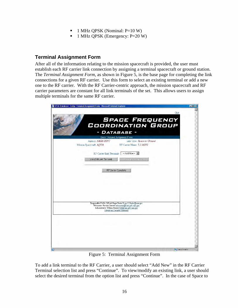
Terminal Assignment Form After all of the information relating to the mission spacecraft is provided, the user must establish each RF carrier link connection by assigning a terminal spacecraft or ground station. The Terminal Assignment Form, as shown in Figure 5, is the base page for completing the link connections for a given RF carrier. Use this form to select an existing terminal or add a new one to the RF carrier. With the RF Carrier-centric approach, the mission spacecraft and RF carrier parameters are constant for all link terminals of the set. This allows users to assign multiple terminals for the same RF carrier.
Figure 5: Terminal Assignment Form
To add a link terminal to the RF Carrier, a user should select “Add New” in the RF Carrier Terminal selection list and press “Continue”. To view/modify an existing link, a user should select the desired terminal from the option list and press “Continue”. In the case of Space to

17
Ground or a Ground to Space link types, the Ground Station Terminal Form is displayed, as shown in Figure 6. Conversely, Figure 7 displays the Spacecraft Terminal Form which is displayed for a Forward or Return link designation. When the user has added all of the desired terminals to the carrier, pressing “RF Carrier Complete” will return the user to the RF Carrier Action Form.
Ground Terminal Definition Form The Terminal Assignment Form calls this form for a link type of Space to Ground or Ground to Space. The information required on the Ground Terminal Definition Form are the parameters associated with the ground station and those associated with the link at the terminal end. The link parameters vary depending on the link type, as with the RF Carrier parameters. Please refer to Table 1. Due to the sharing of resources among agencies, users are allowed to select a ground station from any agency. This differs from the RF Carrier page where a user is restricted to spacecraft belonging to his/her agency. However, users must be extremely cautious in making updates to the ground station. If a change is made for the ground station on this form for a particular link, then the ground station is changed throughout the database. Therefore, users are encouraged to coordinate with operating agencies of the ground stations before making changes. If a user wants to make a change just for their use, then this change should be made in the spread sheet file after it is saved on the user’s local machine. From this form the user has the ability to select three viewing options to follow the database updates: continue without viewing, view the current link, and view all links associated with the RF carrier. The desired option should be selected with the corresponding radio button before click the “Save with Selected Viewing Options” button. Other button selections on this form are “Back” which returns the user to the Terminal Assignment Form, “Reset” which refreshes the page with the database contents, and the “Return to RF Carrier Action Form” to restart from the beginning of the entry process. The view pages are provided to allow users to view all of the data that they have just entered into the database for quick review. Examples of the view pages for the current link and all links for the current carrier are shown in Figures 8 and 9, respectively.
Space Terminal Definition Form The Terminal Assignment Form calls this form for a link type of Forward or Return. The information required on the Space Terminal Definition Form are the parameters associated with the relay spacecraft and those associated with the link to the terminal. The link parameters vary depending on the link type, as with the RF Carrier parameters. Please refer to Table 1.

18
Figure 6: Ground Terminal Definition Form
Figure 7: Space Terminal Definition Form

19
Due to the sharing of resources among agencies, users are allowed to select relay satellites from any agency. This differs from the RF Carrier page where a user is restricted to spacecraft belonging to his/her agency. However, users must be extremely cautious in making updates to the relay. If a change is made for the relay on this form for a particular link, then the relay information is changed throughout the database. Therefore, users are encouraged to coordinate with operating agencies of the relay satellites before making changes. If a user wants to make a change just for their use, then this change should be made in the spread sheet file after it is saved on the user’s local machine. From this form the user has the ability to select three viewing options to follow the database updates: continue without viewing, view the current link, and view all links associated with the RF carrier. The desired selection should be selected with the radio button before click the “Save with Selected Viewing Options” button. Other button selections on this form are “Back” which returns the user to the Terminal Assignment Form, “Reset” which refreshes the page with the database contents, and the “Return to RF Carrier Action Form” to restart from the beginning of the entry process. The view pages are provided to allow users to view all of the data that they have just entered into the database for quick review. Examples of the view pages for the current link and all links for the current carrier are shown in Figures 8 and 9, respectively.
Figure 8: Data View for the Current Link

20
Figure 9: Data View for All Links of the Current RF Carrier

21
Generate a Report
General Instructions Unlike the data entry portion of the site, users have the ability to view data from all of the agencies as well as restricting the list to their own agency’s RF carriers. Selecting “Generate a Report” for the home page will bring up the selection page as shown in Figure 10. There are four report options available to the user for both the case of all agencies and the agency specific report. These are: Summary, Space to Ground, Ground to Space, Return, and Forward. These are described in more detail in the following sections. Each of the options on the page is a hyperlink. Clicking on the option will refresh the page and prompt the user for the frequency range. An example of this is shown in Figure 11.
Figure 10: Reports Selection Page

22
Figure 11: Reports Selection Page with Frequency Request
Note that the selected item appears highlighted on the page when the page is refreshed. After the user enters a start and end for the frequency range, clicking the “Submit” button will generate the spread sheet.
Summary Report The user is prompted as to if the report should be opened or saved to a specified location. When saving the file, please remember to provide a meaning file name. Figure 12 shows a portion of the summary table for a frequency range of 2000 to 3000 MHz. In this case all agencies were considered for the query. The data shown on this report is high-level information for RF Carriers and omits many of the communications details.

23
Figure 12: Summary Table for All Agencies Between 2000 and 3000 MHz
Detailed Reports The other link dependent options provide detailed information in the reports. The formats for these reports are similar to those files already in use by the SFCG. In each case the columns vary slightly corresponding to data relative to the link type and whether the ground stations and satellites are transmitting or receiving. Figure 13 shows an example of the detailed report. For the link specific reports there are two tabs in the file. The first, labeled “Mission Spacecraft”, focuses on the mission satellite and carrier parameters (analogous with the Carrier Definition Form of the entry section) and the second, labeled either “Ground Stations” or “Space Networks”, displays the parameters associated with the link terminal (analogous with either the Ground Terminal Definition Form or the Space Terminal Definition Form of the entry section).

24

25
Figure 13: Both Tabs of the NASA GSFC Specific Space to Ground Links in the 2000 to 3000
MHz Frequency Range


