NSS Space Settlement Journal – Prepared for AIAA Space 2017 – Republished with the permission of the authors 1 Space‐to‐Space Power Beaming (SSPB) -- A Commercial ISS Technology Development, Demonstration, and Deployment (TD 3 ) Mission Gary P. Barnhard 1 Xtraordinary Innovative Space Partnerships, Inc. (XISP-Inc), Cabin John, MD 20818 Daniel Faber 2 XISP-Inc, Cabin John, MD, 20818 Abstract: One of many paths forward for hastening the development of viable applications of space solar power technology is through focused incremental Technology Development, Demonstration, and Deployment (TD3) efforts. This paper addresses one such effort that is moving forward through mission development -- Space- to-Space Power Beaming (SSPB), a commercial International Space Station (ISS) Technology Development, Demonstration, and Deployment (TD3) mission. This paper summarizes the SSPB mission genesis building on foundational research in the field, the mission development work accomplished to date, the evolving concept of operations, and the current mission status. The SSPB mission is intended to help mitigate cost, schedule, and technical risk associated with the short, mid, and long term application of space power and ancillary services beaming technology. This mission involves significant technology development, demonstration, and deployment elements, intended to be orchestrated and implemented in a manner that delivers significant value to some number of customers co‐orbiting with the International Space Station (ISS) as well as serving as a testbed environment for more expansive SSPB TD3 efforts. This paper lays out the TD3 objectives associated with the unbundling of space power systems (i.e., the separation of power generation, transmission, distribution, and loads) and how the authors and their team intend to use that unbundling process to build a bridge over what has euphemistically been called the “technology development valley of death”. The latest estimated deliverable power density and power received values based on the collection efficiency calculations (which have correlated to ground tests by other research efforts) are provided. Power received is calculated for a range of rectenna sizes at a 200 m distance for: multiple frequencies, potential ISS input power levels, and selected transmit aperture areas. In addition, a comparison between estimated delivered power density and the Solar Constant is provided for the orbital distance of immediate interest. The calculated values clearly show that the low end of Ka band, with a delivered power density an order of magnitude less the than Solar Constant is very benign. The high end of Ka band can actually meet some customer requirements at best at a small multiple of the Solar Constant. However, W band frequency can provide a power density an order of magnitude or higher than the Solar Constant. The challenge in all instances is engineering systems with an end-to-end efficiency which is satisfactory and sufficient for the application. The ability to provide power when and where you need it is essential to virtually all aspects of human endeavor, and is enabling for any form of space settlement. Space solar power technology holds the promise of being one of the few large scale energy generation options which can scale to meet the growing electrical energy demand of the world. This mission is a unique opportunity to foster the development of space‐to‐space power beaming by leveraging ISS resources to create a SSPB testbed environment on and near the ISS that supports the development of frequency agnostic radiant energy beaming technology. This paper provides a substantive update on the mission development work that has been accomplished since the original paper was presented at AIAA Space 2016. 1 President & CEO XISP-Inc, AIAA Associate Fellow 2 Chief Technologist XISP-Inc
Transcript
NSS Space Settlement Journal – Prepared for AIAA Space 2017 – Republished with the permission of the authors
1
Space‐to‐Space Power Beaming (SSPB) -- A Commercial ISS
Technology Development, Demonstration, and Deployment
(TD3) Mission
Gary P. Barnhard1
Xtraordinary Innovative Space Partnerships, Inc. (XISP-Inc), Cabin John, MD 20818
Daniel Faber2
XISP-Inc, Cabin John, MD, 20818
Abstract:
One of many paths forward for hastening the development of viable applications of space solar power
technology is through focused incremental Technology Development, Demonstration, and Deployment (TD3)
efforts. This paper addresses one such effort that is moving forward through mission development -- Space-
to-Space Power Beaming (SSPB), a commercial International Space Station (ISS) Technology Development,
Demonstration, and Deployment (TD3) mission. This paper summarizes the SSPB mission genesis building on
foundational research in the field, the mission development work accomplished to date, the evolving concept of
operations, and the current mission status. The SSPB mission is intended to help mitigate cost, schedule, and
technical risk associated with the short, mid, and long term application of space power and ancillary services
beaming technology. This mission involves significant technology development, demonstration, and deployment
elements, intended to be orchestrated and implemented in a manner that delivers significant value to some
number of customers co‐orbiting with the International Space Station (ISS) as well as serving as a testbed
environment for more expansive SSPB TD3 efforts. This paper lays out the TD3 objectives associated with the
unbundling of space power systems (i.e., the separation of power generation, transmission, distribution, and
loads) and how the authors and their team intend to use that unbundling process to build a bridge over what
has euphemistically been called the “technology development valley of death”. The latest estimated deliverable
power density and power received values based on the collection efficiency calculations (which have correlated
to ground tests by other research efforts) are provided. Power received is calculated for a range of rectenna
sizes at a 200 m distance for: multiple frequencies, potential ISS input power levels, and selected transmit
aperture areas. In addition, a comparison between estimated delivered power density and the Solar Constant
is provided for the orbital distance of immediate interest. The calculated values clearly show that the low end
of Ka band, with a delivered power density an order of magnitude less the than Solar Constant is very benign.
The high end of Ka band can actually meet some customer requirements at best at a small multiple of the Solar
Constant. However, W band frequency can provide a power density an order of magnitude or higher than the
Solar Constant. The challenge in all instances is engineering systems with an end-to-end efficiency which is
satisfactory and sufficient for the application. The ability to provide power when and where you need it is
essential to virtually all aspects of human endeavor, and is enabling for any form of space settlement. Space
solar power technology holds the promise of being one of the few large scale energy generation options which
can scale to meet the growing electrical energy demand of the world. This mission is a unique opportunity to
foster the development of space‐to‐space power beaming by leveraging ISS resources to create a SSPB testbed
environment on and near the ISS that supports the development of frequency agnostic radiant energy beaming
technology. This paper provides a substantive update on the mission development work that has been
accomplished since the original paper was presented at AIAA Space 2016.
1 President & CEO XISP-Inc, AIAA Associate Fellow 2 Chief Technologist XISP-Inc
NSS Space Settlement Journal – Prepared for AIAA Space 2017 – Republished with the permission of the authors
2
Nomenclature
Isc = Solar Constant at 1 AU = 0.1367 W/cm2
Pd = power density at the center of the receiving location, W/cm2
P𝑡 = total radiated power from the transmitter, W
A𝑡 = total area of the transmitting antenna, cm2
Ar = total area of the receiving antenna (rectenna), cm2
λ = wavelength, cm
D = separation between the transmitting and receiving antenna apertures, cm
Pr = power received at the rectenna, W
ζ = zeta is a value which relates the physical parameters of the power beaming system to the collection
efficiency, dimensionless
W = diameter the area of an equivalent square rectenna, cm
D = diameter the area of an equivalent square transmitter antenna, cm
R = separation between the transmitting and receiving apertures, cm
I. Introduction
ne of many paths forward for hastening the development of viable applications of space solar power technology
is through focused incremental Technology Development, Demonstration, and Deployment (TD3) efforts which
serve to bridge the “technology development valley of death”. This mission seeks to help mitigate the cost, schedule,
and technical risk associated with the short, mid, and long term applications of space power and ancillary services
beaming. The potential of space solar power technology has been examined in some detail by other researchers
providing both a technical foundation and an inspiration to bring this work to fruition.1-6 This mission provides both
a testbed environment for the technology as well as power and ancillary services of demonstrable value to some
number of customers co‐orbiting with the International Space Station (ISS). This paper lays out the TD3 objectives
associated with the unbundling of space power systems (i.e., the separation of power generation, transmission,
management, and loads)7-24 to enable applications of Space-to-Space and Space-to-Alternate Surface Power Beaming
that are mission enhancing if not mission enabling. We have a unique opportunity to foster the development of space‐to‐space power beaming by leveraging ISS resources to create a space‐to‐space power beaming testbed environment
on and in the vicinity of ISS. This work can be mission enhancing if not mission enabling for a range of Earth facing,
space operations/development, and space exploration missions. Furthermore, this work can develop into space
electrical and ancillary services as a commercial utility infrastructure. Accordingly, this work reinforces the United
States leadership in the global high-tech marketplace as well as providing extraordinary opportunities for international
cooperation and collaboration.
II. Mission Definition
The XISP-Inc Space-to-Space Power Beaming (SSPB) TD3 mission, is a precursor to a Cislunar electrical power
and allied utilities (communications, data, navigation/time) service, the Lunar Power & Light company (LP&L). The
intention of the LP&L Company is to address markets for power and ancillary utilities (i.e., communications, data,
navigation, and time) from the Karman line (100 km) through to the surface of the Moon.
Based on the hypothesis that there are economies of scale to be gained with respect to power generation,
transmission, and distribution in space. An unbundled power system (separating power generation, transmission,
distribution, control, and loads) where transmission and/or distribution occurs via a radiant energy beam can provide
customers new mission-enhancing/mission-enabling technologies for meeting their power and other ancillary utility
requirements, as well as delivering a compelling Return On Investment (ROI) to investors.
This work also addresses both real and perceived cost, schedule, and technical risks associated with Space Solar
Power and ancillary services beaming across multiple venues including: Space-to-Space, Space-to-Alternate Surfaces,
as well as the potential for Space-to-Earth.
The Technology Development components of the SSPB TD3 mission are:
1) Systems/Subsystem Related:
o Multi-band receiving antennas (rectennas) (Ka band, W band, and Optical)
o Optimized Multi-band transceiver (Ka band, W band, and Optical)
o Multi-band phased array transmission apertures (Ka band, W band, and Optical)
o Radiant energy beaming control and safety interlock system
o Water based thrusters for propulsion and active attitude control system
O
NSS Space Settlement Journal – Prepared for AIAA Space 2017 – Republished with the permission of the authors
3
2) Ancillary Utility Related:
o Power/Data/Communications/Navigation/Time Multiplexing within radiant energy beams
o Power and allied utility waveforms for Software Defined Radios (SDR)
o Converged Radio Frequency & Optical SDR electronics
3) Intersecting XISP-Inc Missions:
o Interoperable Network Communications Architecture (INCA) – (interoperable communications networks
to accommodate customer ancillary utility requirements)
o Management Operations Control Applications (MOCA) – (near real-time state models, NASA ARC
Mission Control Technologies OpenMCT software suite)
o Alpha Cube Sat (ACS) – (advanced cubesat design: reflectarray rectenna design, SDR, integrated avionics
package, thruster/attitude control systems, virtual operations center)
o Halfway To Anywhere (HTA) – (bi-modal water and electric propulsion, Trajectory Insert Bus, low energy
trajectory applications)
The Technology Demonstration components of the SSPB TD3 mission are:
1) Radiant energy beaming testbed (integrated evolvable/scalable power and ancillary utilities)
2) Characterization of radiant energy beaming (near realtime, integrated with control)
3) Optimization of radiant energy beaming (near realtime, integrated with control)
4) Formulation and testing of operational rules for the use of radiant energy beaming
5) CubeSat (Flight Test Article) Technology Readiness Level advancement to TRL 8/9
The Technology Deployment components of the SSPB TD3 mission are:
1) ISS Co-orbiting Radiant Energy Beaming (50 m 1 km)
o 6U Cubesat Mobile Servicing Center (MSC) captive test with existing or optimized transmitter
o 6U Cubesat MSC released test with optimized transmitter & rectenna
o OrbitalATK Cygnus pressurized logistics carrier test with optimized transmitter & rectenna
o NanoRacks Commercial Airlock/free-flyer test with optimized transmitter & rectenna (proposed)
o Made In Space manufacturing cell test with optimized transmitter & rectenna (proposed)
2) Evolved/scaled systems will address other markets for power and ancillary utilities delivery in LEO, MEO,
HEO, GEO, Libration/Trajectory Waypoints, Lunar Orbits, and the Lunar Surface.
3) Power and allied utilities delivery will progress as systems are fielded.
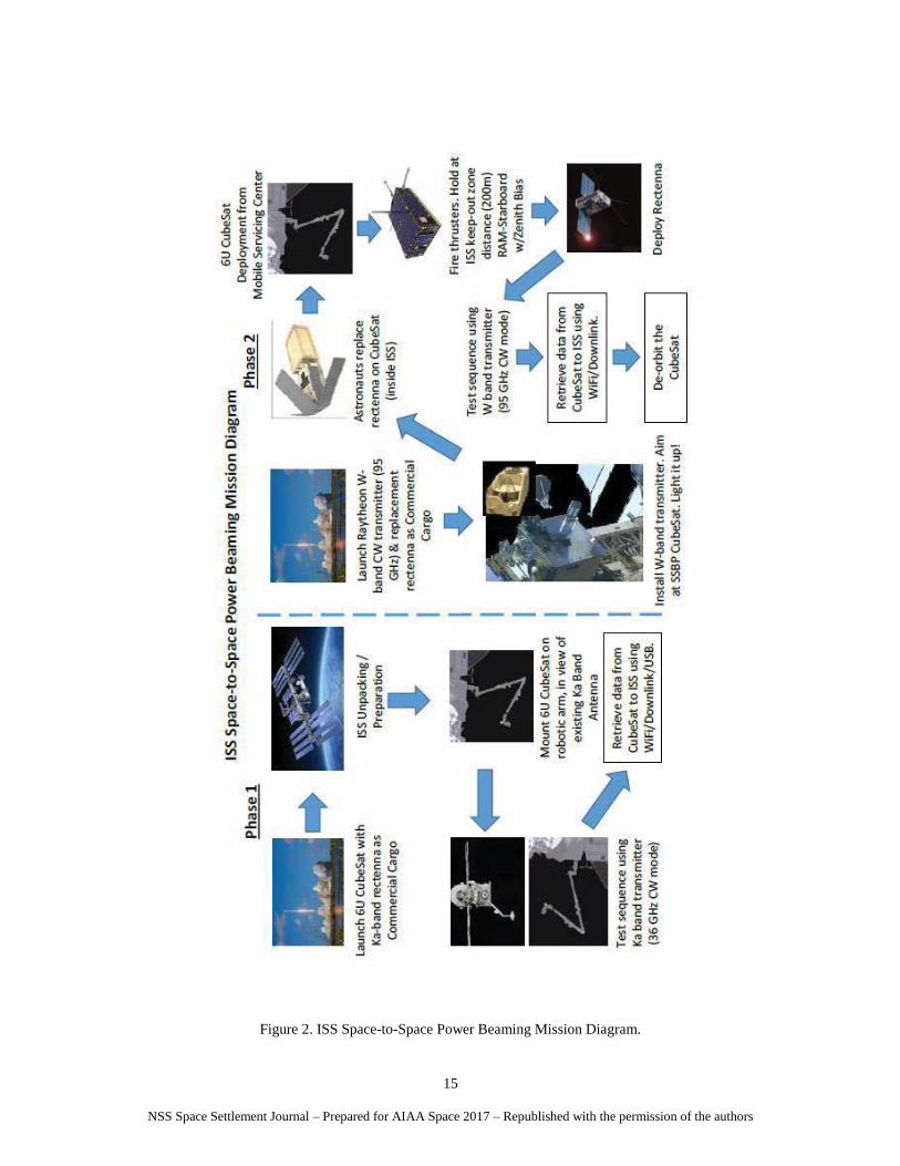
Emergency Servicing Augment Backup Primary.
The ISS is a unique resource for this TD3 mission. It our optimal “testbed environment” that features microgravity,
vacuum, temperature range, vantage point, as well as a combination of teleoperated, automated, crew-tended, and
hands on crew operations that can be optimized for productivity. Furthermore, ISS provides the first “customers”,
ISS co-orbiting systems which will require fault tolerant power and allied utilities to accelerate, enhance, or enable,
the ultimate deployment of their systems.
Attempting, to simulate on the ground the operational testbed environment required for the characterization,
optimization, and definition of the operational rules for using a radiant energy beam as part of an unbundled space
electrical power system for supporting co-orbiting spacecraft is untenable on an integrated basis. Doing whatever
ground tests are possible on a piecewise basis will be an integral part of the mission execution.
The ISS platform will provide a cost effective test-bed for future development, characterization and verification
of more advanced beamed power technologies. In addition, the orbital location of ISS provides access to an
ionospheric regime whose effects on wave propagation are not as well understood as those from either the atmosphere,
or deeper regions of space, particularly at the frequencies and beam intensities in question.
The SSPB mission facilitates ISS co-orbiting systems by providing the fault tolerant power and ancillary utilities
which allow for normal ISS operations. These co-orbiting systems will be able to accommodate additional
experiments which are currently not feasible because they require more stringent microgravity conditions, beam
pointing accuracy requirements, alternate safety protocols, and/or would otherwise interfere with ISS operations.
SSPB missions will be able to address markets in LEO, MEO, HEO, GEO, Libration/Trajectory Waypoints, Lunar
Orbits, Lunar Surface, and asteroidal surfaces. These follow-on missions are unlikely to happen on as timely and/or
cost effective basis without accomplishment of the SSPB TD3 mission on ISS. A necessary precursor to these more
advanced applications is the accomplishment of our proposed TD3 mission.
SSPB will lower costs and establish a robust foundation for providing electrical and ancillary utilities in Cislunar
space. A Space-to-Earth power beaming capability could provide power on demand anywhere on Earth within line-
of-sight of a space-based power facility. On a small scale, this could enable low-impact human activities in off-the-
grid areas, for research, tourism, or disaster relief. Large-scale power beaming from Space-to-Earth could provide
NSS Space Settlement Journal – Prepared for AIAA Space 2017 – Republished with the permission of the authors
4
energy on Earth without worries of releasing carbon or radioactive materials into the atmosphere, profoundly
improving life for everyone on Earth.
The Space-to-Space Power Beaming (SSPB) mission is a NASA recognized XISP-Inc commercial mission
proceeding under a combination of existing and pending NASA Space Act Agreement authority as well as evolving
commercial, university, and non-governmental organization agreements.
A. What is the problem being addressed?
XISP‐Inc has hypothesized that unbundling power systems (i.e., the separation of power generation, transmission,
distribution, and loads) can:
1) reduce spacecraft complexity and thereby reduce cost, schedule, and technical risk
2) reduce mass and/or volume required to accomplish a given mission
3) reallocate mass and/or volume to enhance or enable missions
4) indirectly impart additional delta‐V along velocity vectors of choice to enhance or enable missions
5) foster the development of loosely coupled modular structures to enable:
a. formation flying of multiple spacecraft (e.g., interferometric groups, swarms)
b. distributed payload and subsystem infrastructure to simplify the accommodation of multiple plug‐in
and plug‐out interfaces
c. large scale adaptable space structures that minimize conducted thermal and/or structural loads.
Furthermore, by the realization of the above and taking advantage of the economies of scale power and ancillary
services can be provided to range of Cislunar markets starting with the co-orbiting environment of the ISS.
B. What is the Economic Benefit and Commercial Relevance?
It is anticipated that the TD3 mission will provide beamed power and allied utilities to ISS co-orbiting customers
at a level sufficient to warrant the mission investment, and in the process retire both real and/or perceived cost,
schedule, and technical risk associated with the evolved/scalable systems required for the next phase of investment.
Accordingly, we anticipate that the TD3 mission will lay the technological foundation for our Cislunar electrical power
and allied utilities service, the Lunar Power & Light (LP&L) Company.
The capability to physically separate solar electricity generation from point-of-use will enable a wide range of
applications, operations, and exploration missions not previously possible. By reducing constraints imposed by solar
arrays we can realize mass, volume, increased sensor system efficiency, reliability and maintenance in a harsh
operational environment.
Mission architectures are made possible for distributed payloads and sensors with application in disaggregated
systems in Earth orbit and for demanding deep space missions. This is particularly useful for dust and shadow
environments where sunlight may be blocked such as asteroid surface activities and dark lunar craters. Also, mission
architectures are enabled for disaggregated spacecraft where portions of the “swarm” may experience shadow. Power
beaming can be used large solar arrays are not desirable or feasible on the sensor platform due to spacecraft dynamics
or thermal/structural loads. Cost-effective augmentation of power to satellites with degraded solar arrays will be a
priority service offering.
Achievable power densities at a specified distance are dramatically impacted by increasing beam frequency despite
an anticipated fall off in efficiency. Even more striking is the almost an order of magnitude reduction in rectenna area
required moving from Ka Band to W Band. Having a validated SSPB testbed will allow the piecewise optimization
of the end-to-end system (i.e., reducing and/or allowing the reallocation of power, mass, and volume), as well as
allowing for incremental upgrades, and graceful degradation of a modularized system of systems. One of the mission’s
goals is to advance the Technological Readiness Level (TRL) of radiant energy beaming technology to the point where
it can be deployed in support of one or more missions (i.e., moving from TRL 4 to 8/9).
Currently, the largest customers for power in Cislunar space are the Geosynchronus Communications Satellites
(~443 active) with electrical energy demands ranging from ~2 to ~20 kW. As the satellite communication market
bifurcates into a new market for large consellations of small satellites to serve acceptance level customers (Quality of
Service (QoS) provided is what can be delivered) and a maturing QoS driven market which is evolving to larger and
increasingly immortal platforms with plug-in/plug-out technology and rapidly increasing electrical energy demands.
The rate of improvement in transponder technology means that satellites with a 15 year design lift are now obsolete
after about 8 years, because the new satellites have such dramatically greater bandwidth. The industry wants a satellite
that lasts half as long and costs half a much, which cannot be achieved by simply scaling the size of the satellite.
The XISP‐Inc proposed cubesat target demonstrating power beaming from ISS will require the cooperation of
several elements of NASA and Industry, but would result in near term demonstration of space‐to‐space power
beaming, and allow rapid iteration of designs and experiments.
NSS Space Settlement Journal – Prepared for AIAA Space 2017 – Republished with the permission of the authors
5
Establishing a functioning ISS power beaming testbed could allow experimentation and validation of components
of larger power beaming systems, and reduce the risk of the development of the larger dedicated systems
Although the experiments with ISS and cubesats would be small scale, there could be immediate applications for
subsatellites near ISS, as well as designs for distributed payloads and sensors for deep space missions including lunar
and asteroidal assay work.
A primary mission of XISP‐Inc is to develop cooperative arrangements with different parts of NASA and different
industry partners. The early implementation of a power beam demonstration on ISS, coordinated by XISP‐Inc, could
enhance and enable the demonstration of other power beaming designs.
There is no technology currently available that can allow separation of solar arrays from other spacecraft systems
(e.g. the sensor package, pointing/mobility systems, communication equipment). State of the art beamed power
systems are at TRL 4. The proposed demonstration will be the first ever commercial system test of in-space beamed
power, advancing this technology to TRL 8/9.
The primary innovations are:
• the physical separation of electricity generation from point-of-use
• the ability to characterize and optimize high frequency (Ka, W, and optical) power transfer
• SSPB in a safe and efficient manner (beaming control and safety interlock system)
5) Optimization/Scaling/Efficacy of the Solution Set
The essential issue is answering the question of “Where does it make sense to use the technology?”
NSS Space Settlement Journal – Prepared for AIAA Space 2017 – Republished with the permission of the authors
19
F. SSPB & Commercial Requirements
For the purposes of this work we have the following commercial mission requirements to address:
1) Asteroidal Assay
a. Co-orbiting motherships with deployable sensors
b. Cislunar proving ground mission for Space-to-Alternate Surface radiant energy beaming applications
2) ISS Co-orbiting Free-flyers
a. Micro-g manufacturing cells
3) Propulsion (delta-V augmentation)
a. Out bound & cycling spacecraft
b. Orbital debris management
4) Plug-In/Plug-Out Infrastructure Platforms
a. Communications, Navigation, Power, etc.
b. Earth facing, space operations, and space exploration
i. Emergency Preparedness and Response Networks
ii. Cislunar infrastructure and adhoc communications & navigation mesh networks
5) Operational Cadence/Cycle Evolution
a. International Lunar Decade Support
G. Mathematics of Power Beaming
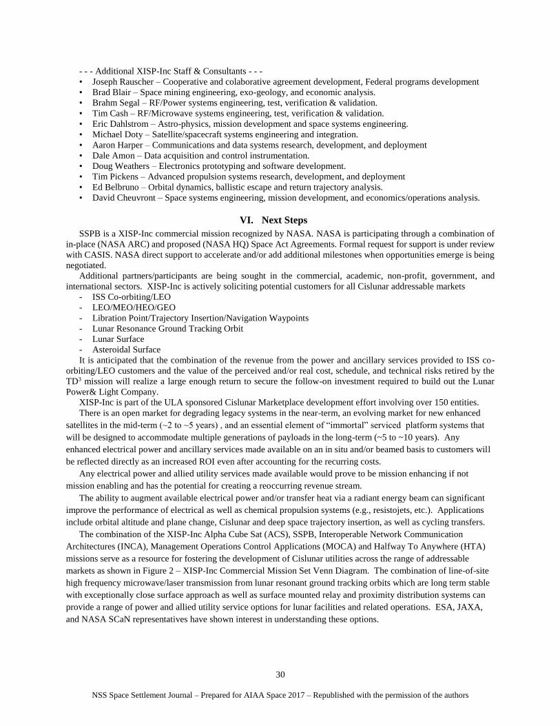
For the purposes of understanding the mathematics of power beaming at an application level there are four
schematic elements that must be addressed1.
1) DC to Microwave Conversion (70-90% efficient, circa 1992) {current estimate is ~95% depending on voltage
multiplier ratio}
2) Beam Forming Antenna (70-97% efficient, circa 1992) {current estimate is comparable}
3) Free Space Transmission (5-95% efficient, circa 1992) {current estimate is comparable}
4) Reception Conversion to DC (85-92% efficient, circa 1992) {current estimate is ~95% depending on voltage
multiplier ratio}
The theoretical maximum possible DC to DC Efficiency was estimated to be ~76%, circa 1992{use of one cycle
modulation could increase this to between 85-95%, not pulse width modulation (pwm)}. The experimental DC to
DC efficiency established was ~54%, circa 1992 {this is open area of research where significant increase is
anticipated}. While the higher component efficiency values shown above are well established for low frequency
microwaves (< 6 GHz) this is not the case for higher frequencies. Recent data suggests for high frequencies the
range estimates should be adjusted to:
1) DC to Microwave Conversion (10%-60% efficient, circa 2016)
2) Beam Forming Antenna (50%-80% efficient, circa 2016 assuming the use of reflectors)
3) Free Space Transmission (1%-90% efficient, circa 2016)
4) Reception Conversion to DC (37%-72% efficient, circa 2016) [1-6, 25]
The DC to Microwave Conversion and the Beam Forming Antenna efficiencies have very high observed values
that have just improved with time over the values cited and will be a given for the existing ISS transmitters and
therefore have been neglected to simplify the initial analysis. However, they will need to be addressed in the
development of any optimized radiant energy beam transmitter.
The greatest efficiency variability is with Free Space Transmission. For applications where the receiving antenna
(rectenna) size is limited and there is a need to calculate the illuminating power density, pd, equation (1) can be used1.
Pd = (At)(Pt) / (λ)2(D)2 (1)
Pd is the power density at the center of the receiving location [W/cm2]
Pt is the total radiated power from the transmitter [W]
At is the total area of the transmitting antenna [cm2]
λ is the wavelength [cm]
D is the separation between the transmitting and receiving apertures [cm]
The area of ISS Space Communication and Navigation (SCaN) Test Bed (STB) Ka Band Transmitter Dish ~1642
cm2 is a placeholder value for available ISS transmitters and is assumed to be the minimum size for an ISS W
transmitter phased array plate.
The maximum area of the proposed ISS W Band transmitter phased array plate is 10000 cm2.
NSS Space Settlement Journal – Prepared for AIAA Space 2017 – Republished with the permission of the authors
20
The JEM Exposed Facility (EF) Utility Port input power is 3000 W maximum using one ISS remote power
controller module, and 6000 W maximum using two ISS remote power controllers, subject to input power availability.
The ISS spherical zone of exclusion is a 200 m radius extending from the ISS center of mass.
The Pd test cases that have been calculated so far include:
Case 1: Ka Band Low 26.5 GHz,
D = 200 m, 𝐴r =100 cm2 to 10000 cm2, λ=1.13 cm, 𝐴𝑡 = 1642 cm2, 𝑃𝑡 = 3000 W D = 200 m, 𝐴r =100 cm2 to 10000 cm2, λ=1.13 cm, 𝐴𝑡 = 1642 cm2, 𝑃𝑡 = 6000 W D = 200 m, 𝐴r =100 cm2 to 10000 cm2, λ=1.13 cm, 𝐴𝑡 = 10000 cm2, 𝑃𝑡 = 3000 W D = 200 m, 𝐴r =100 cm2 to 10000 cm2, λ=1.13 cm, 𝐴𝑡 = 10000 cm2, 𝑃𝑡 = 6000 W
Case 2: Ka Band Target 36 GHz,
D = 200 m, 𝐴r =100 cm2 to 10000 cm2, λ=0.833 cm, 𝐴𝑡 = 1642 cm2, 𝑃𝑡 = 3000 W D = 200 m, 𝐴r =100 cm2 to 10000 cm2, λ=0.833 cm, 𝐴𝑡 = 1642 cm2, 𝑃𝑡 = 6000 W D = 200 m, 𝐴r =100 cm2 to 10000 cm2, λ=0.833 cm, 𝐴𝑡 = 10000 cm2, 𝑃𝑡 = 3000 W D = 200 m, 𝐴r =100 cm2 to 10000 cm2, λ=0.833 cm, 𝐴𝑡 = 10000 cm2, 𝑃𝑡 = 6000 W
Case 3: W Band Target 95 GHz,
D = 200 m, 𝐴r =100 cm2 to 10000 cm2, λ=0.316 cm, 𝐴𝑡 = 1642 cm2, 𝑃𝑡 = 3000 W D = 200 m, 𝐴r =100 cm2 to 10000 cm2, λ=0.316 cm, 𝐴𝑡 = 1642 cm2, 𝑃𝑡 = 6000 W D = 200 m, 𝐴r =100 cm2 to 10000 cm2, λ=0.316 cm, 𝐴𝑡 = 10000 cm2, 𝑃𝑡 = 3000 W D = 200 m, 𝐴r =100 cm2 to 10000 cm2, λ=0.316 cm, 𝐴𝑡 = 10000 cm2, 𝑃𝑡 = 6000 W
Reception conversion to DC have very high observed values that have improved with time over the values cited
and therefore have been neglected to simplify the initial analysis. However, it will need to be addressed in the
development of any optimized radiant energy beam rectenna with relative development risk increasing with frequency
of the radiant energy beam. In cases where the rectenna aperture is not small in proportion to the transmitter aperture,
transmitter power levels are high, and the frequency is high, power received (Pr) calculations break down using the
far-field equations. Accordingly, the Pr is calculated using the collection efficiency method25 shown in equations (2)
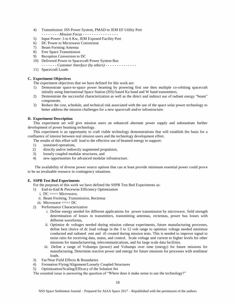
and (3) as well as Figure 1 - Power Transmission Efficency25 instead of the far-field equations.
Pr = (ζ ) (Pt) (2)
where
Pr is the power received at the rectenna [W]
Pt is the total radiated power from the transmitter [W]
ζ is relates the physical parameters of the power beaming system to the collection efficiency
ζ = (D )(W) / (λ)(R) (3)
where
ζ “zeta” is the dimensionless value which relates the physical parameters of the power beaming system to the
collection efficiency 25
W is the diameter the area of an equivalent square rectenna which equals (2)(Ar /p) 1/2 [cm]
D is the diameter the area of an equivalent square transmitter antenna which equals (2)(At /p) 1/2 [cm]
Ar is the total area of the rectenna [cm2]
At is the total area of the transmitter antenna [cm2]
λ is the wavelength [cm]
R is the separation between the transmitting and receiving apertures [cm]
NSS Space Settlement Journal – Prepared for AIAA Space 2017 – Republished with the permission of the authors
21
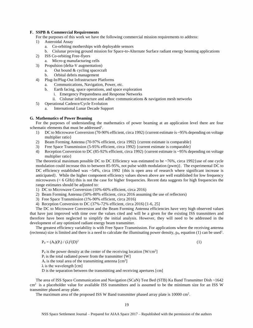
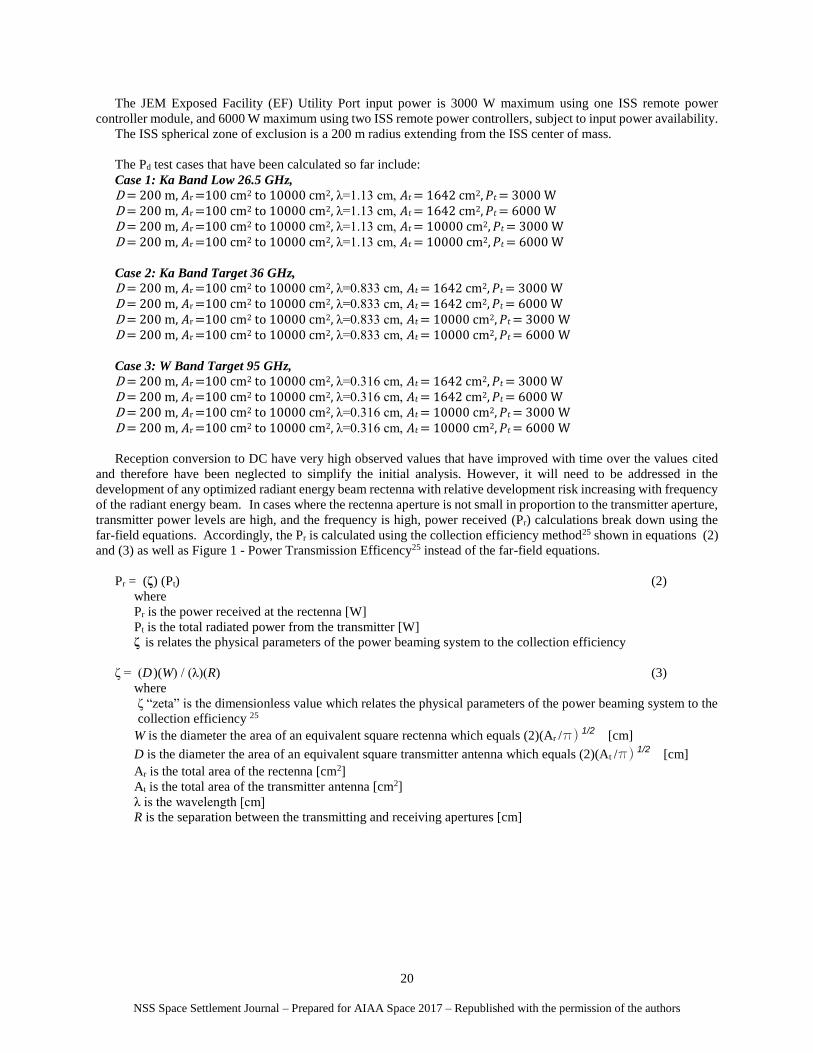
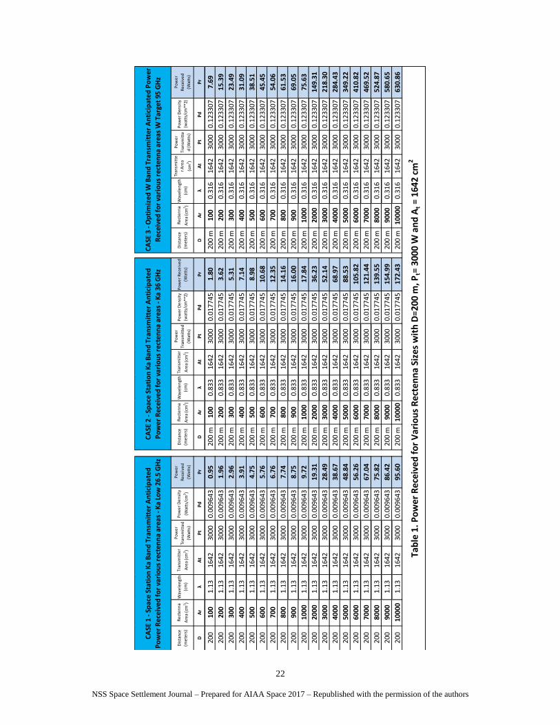
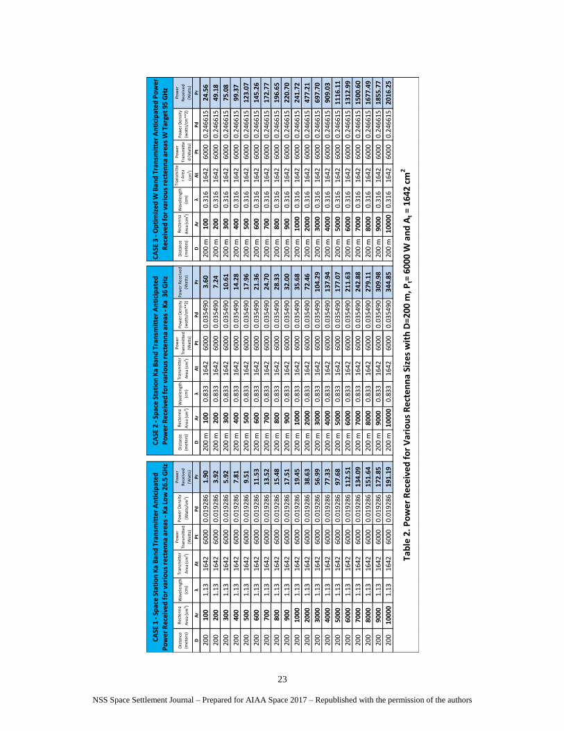
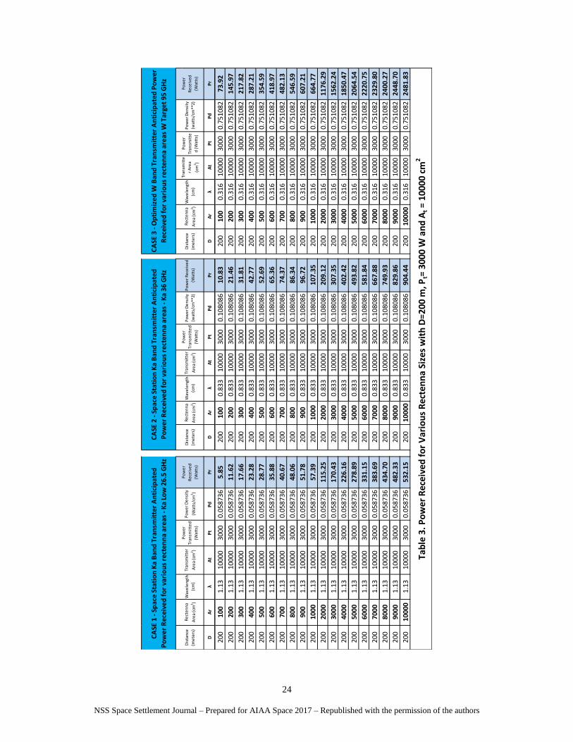
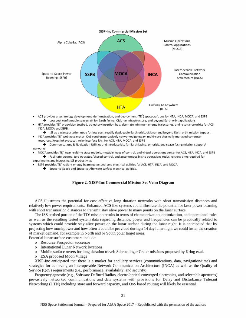
The rectenna efficiencies are based of the peak incident power density at the rectenna’s center and assumed to be
constant across the rectenna area (a reasonable approximation for small rectenna sizes). For the test cases 1, 2, and 3
Pr has been calculated for rectenna sizes ranging from 100 cm2 to 10000 cm2 and are shown in following tables:
Table 1. Power Received for Various Rectenna Sizes with D=200 m, Pt= 3000 W and At = 1642 cm2
Table 2. Power Received for Various Rectenna Sizes with D=200 m, Pt= 6000 W and At = 1642 cm2
Table 3. Power Received for Various Rectenna Sizes with D=200 m, Pt= 3000 W and At = 10000 cm2
Table 4. Power Received for Various Rectenna Sizes with D=200 m, Pt= 6000 W and At = 10000 cm2
NSS Space Settlement Journal – Prepared for AIAA Space 2017 – Republished with the permission of the authors
22
DA
rλ
At
Pt
Pd
P
rD
Ar
λA
tP
tP
d
Pr
DA
rλ
At
Pt
Pd
P
r
200
100
1.13
1642
3000
0.00
9643
0.95
200
m10
00.
833
1642
3000
0.01
7745
1.80
200
m10
00.
316
1642
3000
0.12
3307
7.69
200
200
1.13
1642
3000
0.00
9643
1.96
200
m20
00.
833
1642
3000
0.01
7745
3.62
200
m20
00.
316
1642
3000
0.12
3307
15.3
9
200
300
1.13
1642
3000
0.00
9643
2.96
200
m30
00.
833
1642
3000
0.01
7745
5.31
200
m30
00.
316
1642
3000
0.12
3307
23.4
9
200
400
1.13
1642
3000
0.00
9643
3.91
200
m40
00.
833
1642
3000
0.01
7745
7.14
200
m40
00.
316
1642
3000
0.12
3307
31.0
9
200
500
1.13
1642
3000
0.00
9643
4.75
200
m50
00.
833
1642
3000
0.01
7745
8.98
200
m50
00.
316
1642
3000
0.12
3307
38.5
1
200
600
1.13
1642
3000
0.00
9643
5.76
200
m60
00.
833
1642
3000
0.01
7745
10.6
820
0 m
600
0.31
616
4230
000.
1233
0745
.45
200
700
1.13
1642
3000
0.00
9643
6.76
200
m70
00.
833
1642
3000
0.01
7745
12.3
520
0 m
700
0.31
616
4230
000.
1233
0754
.06
200
800
1.13
1642
3000
0.00
9643
7.74
200
m80
00.
833
1642
3000
0.01
7745
14.1
620
0 m
800
0.31
616
4230
000.
1233
0761
.53
200
900
1.13
1642
3000
0.00
9643
8.75
200
m90
00.
833
1642
3000
0.01
7745
16.0
020
0 m
900
0.31
616
4230
000.
1233
0769
.05
200
1000
1.13
1642
3000
0.00
9643
9.72
200
m10
000.
833
1642
3000
0.01
7745
17.8
420
0 m
1000
0.31
616
4230
000.
1233
0775
.63
200
2000
1.13
1642
3000
0.00
9643
19.3
120
0 m
2000
0.83
316
4230
000.
0177
4536
.23
200
m20
000.
316
1642
3000
0.12
3307
149.
31
200
3000
1.13
1642
3000
0.00
9643
28.4
920
0 m
3000
0.83
316
4230
000.
0177
4552
.14
200
m30
000.
316
1642
3000
0.12
3307
218.
30
200
4000
1.13
1642
3000
0.00
9643
38.6
720
0 m
4000
0.83
316
4230
000.
0177
4568
.97
200
m40
000.
316
1642
3000
0.12
3307
284.
43
200
5000
1.13
1642
3000
0.00
9643
48.8
420
0 m
5000
0.83
316
4230
000.
0177
4588
.53
200
m50
000.
316
1642
3000
0.12
3307
349.
22
200
6000
1.13
1642
3000
0.00
9643
56.2
620
0 m
6000
0.83
316
4230
000.
0177
4510
5.82
200
m60
000.
316
1642
3000
0.12
3307
410.
82
200
7000
1.13
1642
3000
0.00
9643
67.0
420
0 m
7000
0.83
316
4230
000.
0177
4512
1.44
200
m70
000.
316
1642
3000
0.12
3307
469.
52
200
8000
1.13
1642
3000
0.00
9643
75.8
220
0 m
8000
0.83
316
4230
000.
0177
4513
9.55
200
m80
000.
316
1642
3000
0.12
3307
524.
87
200
9000
1.13
1642
3000
0.00
9643
86.4
220
0 m
9000
0.83
316
4230
000.
0177
4515
4.99
200
m90
000.
316
1642
3000
0.12
3307
580.
65
200
1000
01.
1316
4230
000.
0096
4395
.60
200
m10
000
0.83
316
4230
000.
0177
4517
2.43
200
m10
000
0.31
616
4230
000.
1233
0763
0.86
Po
we
r D
en
sity
(wat
ts/c
m**
2)
Po
we
r R
ece
ive
d
(Wat
ts)
Dis
tan
ce
(me
ters
)
Re
cte
nn
a
Are
a (c
m2 )
Tab
le 1
. Po
wer
Rec
eive
d f
or
Var
iou
s R
ecte
nn
a Si
zes
wit
h D
=200
m, P
t= 3
000
W a
nd
At =
164
2 cm
2
Po
we
r
Re
ceiv
ed
(Wat
ts)
Dis
tan
ce
(me
ters
)
Re
cte
nn
a
Are
a (c
m2 )
Wav
ele
ngt
h
(cm
)
Tran
smit
ter
Are
a (c
m2 )
CA
SE 1
- Sp
ace
Stat
ion
Ka
Ban
d T
ran
smit
ter
An
tici
pat
ed
Po
wer
Rec
eive
d f
or
vari
ou
s re
cten
na
area
s - K
a Lo
w 2
6.5
GH
z
CA
SE 2
- Sp
ace
Stat
ion
Ka
Ban
d T
ran
smit
ter
An
tici
pat
ed
Po
wer
Rec
eive
d f
or
vari
ou
s re
cten
na
area
s - K
a 36
GH
z
CA
SE 3
- O
pti
miz
ed W
Ban
d T
ran
smit
ter
An
tici
pat
ed P
ow
er
Rec
eive
d f
or
vari
ou
s re
cten
na
area
s W
Tar
get
95 G
Hz
Dis
tan
ce
(me
ters
)
Re
cte
nn
a
Are
a (c
m2 )
Wav
ele
ngt
h
(cm
)
Tran
smit
ter
Are
a (c
m2 )
Po
we
r
Tran
smit
ted
(Wat
ts)
Po
we
r D
en
sity
(Wat
ts/c
m2 )
Wav
ele
ngt
h
(cm
)
Tran
smit
te
r A
rea
(cm
2 )
Po
we
r
Tran
smit
te
d (
Wat
ts)
Po
we
r D
en
sity
(wat
ts/c
m**
2)
Po
we
r
Re
ceiv
ed
(Wat
ts)
Po
we
r
Tran
smit
ted
(Wat
ts)
NSS Space Settlement Journal – Prepared for AIAA Space 2017 – Republished with the permission of the authors
23
DA
rλ
At
Pt
Pd
P
rD
Ar
λA
tP
tP
d
Pr
DA
rλ
At
Pt
Pd
P
r
200
100
1.13
1642
6000
0.01
9286
1.90
200
m10
00.
833
1642
6000
0.03
5490
3.60
200
m10
00.
316
1642
6000
0.24
6615
24.5
6
200
200
1.13
1642
6000
0.01
9286
3.92
200
m20
00.
833
1642
6000
0.03
5490
7.24
200
m20
00.
316
1642
6000
0.24
6615
49.1
8
200
300
1.13
1642
6000
0.01
9286
5.92
200
m30
00.
833
1642
6000
0.03
5490
10.6
120
0 m
300
0.31
616
4260
000.
2466
1575
.08
200
400
1.13
1642
6000
0.01
9286
7.81
200
m40
00.
833
1642
6000
0.03
5490
14.2
820
0 m
400
0.31
616
4260
000.
2466
1599
.37
200
500
1.13
1642
6000
0.01
9286
9.51
200
m50
00.
833
1642
6000
0.03
5490
17.9
620
0 m
500
0.31
616
4260
000.
2466
1512
3.07
200
600
1.13
1642
6000
0.01
9286
11.5
320
0 m
600
0.83
316
4260
000.
0354
9021
.36
200
m60
00.
316
1642
6000
0.24
6615
145.
26
200
700
1.13
1642
6000
0.01
9286
13.5
220
0 m
700
0.83
316
4260
000.
0354
9024
.70
200
m70
00.
316
1642
6000
0.24
6615
172.
77
200
800
1.13
1642
6000
0.01
9286
15.4
820
0 m
800
0.83
316
4260
000.
0354
9028
.33
200
m80
00.
316
1642
6000
0.24
6615
196.
65
200
900
1.13
1642
6000
0.01
9286
17.5
120
0 m
900
0.83
316
4260
000.
0354
9032
.00
200
m90
00.
316
1642
6000
0.24
6615
220.
70
200
1000
1.13
1642
6000
0.01
9286
19.4
520
0 m
1000
0.83
316
4260
000.
0354
9035
.68
200
m10
000.
316
1642
6000
0.24
6615
241.
72
200
2000
1.13
1642
6000
0.01
9286
38.6
320
0 m
2000
0.83
316
4260
000.
0354
9072
.46
200
m20
000.
316
1642
6000
0.24
6615
477.
21
200
3000
1.13
1642
6000
0.01
9286
56.9
920
0 m
3000
0.83
316
4260
000.
0354
9010
4.29
200
m30
000.
316
1642
6000
0.24
6615
697.
70
200
4000
1.13
1642
6000
0.01
9286
77.3
320
0 m
4000
0.83
316
4260
000.
0354
9013
7.94
200
m40
000.
316
1642
6000
0.24
6615
909.
03
200
5000
1.13
1642
6000
0.01
9286
97.6
820
0 m
5000
0.83
316
4260
000.
0354
9017
7.07
200
m50
000.
316
1642
6000
0.24
6615
1116
.11
200
6000
1.13
1642
6000
0.01
9286
112.
5120
0 m
6000
0.83
316
4260
000.
0354
9021
1.63
200
m60
000.
316
1642
6000
0.24
6615
1312
.99
200
7000
1.13
1642
6000
0.01
9286
134.
0920
0 m
7000
0.83
316
4260
000.
0354
9024
2.88
200
m70
000.
316
1642
6000
0.24
6615
1500
.60
200
8000
1.13
1642
6000
0.01
9286
151.
6420
0 m
8000
0.83
316
4260
000.
0354
9027
9.11
200
m80
000.
316
1642
6000
0.24
6615
1677
.49
200
9000
1.13
1642
6000
0.01
9286
172.
8520
0 m
9000
0.83
316
4260
000.
0354
9030
9.98
200
m90
000.
316
1642
6000
0.24
6615
1855
.77
200
1000
01.
1316
4260
000.
0192
8619
1.19
200
m10
000
0.83
316
4260
000.
0354
9034
4.85
200
m10
000
0.31
616
4260
000.
2466
1520
16.2
5
Po
we
r
Re
ceiv
ed
(Wat
ts)
Tab
le 2
. Po
wer
Rec
eive
d f
or
Va
rio
us
Rec
ten
na
Size
s w
ith
D=2
00 m
, Pt=
600
0 W
an
d A
t = 1
642
cm2
Re
cte
nn
a
Are
a (c
m2)
Wav
ele
ngt
h
(cm
)
Tran
smit
te
r A
rea
(cm
2)
Po
we
r
Tran
smit
te
d (
Wat
ts)
Po
we
r D
en
sity
(wat
ts/c
m**
2)
Tran
smit
ter
Are
a (c
m2)
Po
we
r
Tran
smit
ted
(Wat
ts)
Po
we
r D
en
sity
(wat
ts/c
m**
2)
Po
we
r R
ece
ive
d
(Wat
ts)
Dis
tan
ce
(me
ters
)
Po
we
r D
en
sity
(Wat
ts/c
m2)
Po
we
r
Re
ceiv
ed
(Wat
ts)
Dis
tan
ce
(me
ters
)
Re
cte
nn
a
Are
a (c
m2 )
Wav
ele
ngt
h
(cm
)
CA
SE 1
- Sp
ace
Stat
ion
Ka
Ban
d T
ran
smit
ter
An
tici
pat
ed
Po
wer
Rec
eive
d f
or
vari
ou
s re
cten
na
area
s - K
a Lo
w 2
6.5
GH
z
CA
SE 2
- Sp
ace
Stat
ion
Ka
Ban
d T
ran
smit
ter
An
tici
pat
ed
Po
wer
Rec
eive
d f
or
vari
ou
s re
cten
na
area
s - K
a 3
6 G
Hz
CA
SE 3
- O
pti
miz
ed W
Ban
d T
ran
smit
ter
An
tici
pat
ed P
ow
er
Rec
eive
d f
or
vari
ou
s re
cten
na
area
s W
Tar
get
95 G
Hz
Dis
tan
ce
(me
ters
)
Re
cte
nn
a
Are
a (c
m2)
Wav
ele
ngt
h
(cm
)
Tran
smit
ter
Are
a (c
m2)
Po
we
r
Tran
smit
ted
(Wat
ts)
NSS Space Settlement Journal – Prepared for AIAA Space 2017 – Republished with the permission of the authors
24
DA
rλ
At
Pt
Pd
P
rD
Ar
λA
tP
tP
d
Pr
DA
rλ
At
Pt
Pd
P
r
200
100
1.13
1000
030
000.
0587
365.
8520
010
00.
833
1000
030
000.
1080
8610
.83
200
100
0.31
610
000
3000
0.75
1082
73.9
2
200
200
1.13
1000
030
000.
0587
3611
.62
200
200
0.83
310
000
3000
0.10
8086
21.4
620
020
00.
316
1000
030
000.
7510
8214
5.97
200
300
1.13
1000
030
000.
0587
3617
.66
200
300
0.83
310
000
3000
0.10
8086
31.8
120
030
00.
316
1000
030
000.
7510
8221
7.82
200
400
1.13
1000
030
000.
0587
3623
.28
200
400
0.83
310
000
3000
0.10
8086
42.7
720
040
00.
316
1000
030
000.
7510
8228
7.21
200
500
1.13
1000
030
000.
0587
3628
.77
200
500
0.83
310
000
3000
0.10
8086
52.6
920
050
00.
316
1000
030
000.
7510
8235
4.59
200
600
1.13
1000
030
000.
0587
3635
.88
200
600
0.83
310
000
3000
0.10
8086
65.3
620
060
00.
316
1000
030
000.
7510
8241
8.97
200
700
1.13
1000
030
000.
0587
3640
.67
200
700
0.83
310
000
3000
0.10
8086
74.3
720
070
00.
316
1000
030
000.
7510
8248
2.13
200
800
1.13
1000
030
000.
0587
3648
.06
200
800
0.83
310
000
3000
0.10
8086
86.3
420
080
00.
316
1000
030
000.
7510
8254
6.59
200
900
1.13
1000
030
000.
0587
3651
.78
200
900
0.83
310
000
3000
0.10
8086
96.7
220
090
00.
316
1000
030
000.
7510
8260
7.21
200
1000
1.13
1000
030
000.
0587
3657
.39
200
1000
0.83
310
000
3000
0.10
8086
107.
3520
010
000.
316
1000
030
000.
7510
8266
4.77
200
2000
1.13
1000
030
000.
0587
3611
5.25
200
2000
0.83
310
000
3000
0.10
8086
209.
1220
020
000.
316
1000
030
000.
7510
8211
76.2
9
200
3000
1.13
1000
030
000.
0587
3617
0.43
200
3000
0.83
310
000
3000
0.10
8086
307.
3520
030
000.
316
1000
030
000.
7510
8215
62.2
4
200
4000
1.13
1000
030
000.
0587
3622
6.16
200
4000
0.83
310
000
3000
0.10
8086
402.
4220
040
000.
316
1000
030
000.
7510
8218
50.4
7
200
5000
1.13
1000
030
000.
0587
3627
8.89
200
5000
0.83
310
000
3000
0.10
8086
493.
8220
050
000.
316
1000
030
000.
7510
8220
64.5
4
200
6000
1.13
1000
030
000.
0587
3633
1.15
200
6000
0.83
310
000
3000
0.10
8086
581.
8420
060
000.
316
1000
030
000.
7510
8222
20.7
5
200
7000
1.13
1000
030
000.
0587
3638
3.69
200
7000
0.83
310
000
3000
0.10
8086
667.
8820
070
000.
316
1000
030
000.
7510
8223
29.8
0
200
8000
1.13
1000
030
000.
0587
3643
4.70
200
8000
0.83
310
000
3000
0.10
8086
749.
9320
080
000.
316
1000
030
000.
7510
8224
00.2
7
200
9000
1.13
1000
030
000.
0587
3648
2.33
200
9000
0.83
310
000
3000
0.10
8086
829.
8620
090
000.
316
1000
030
000.
7510
8224
48.7
0
200
1000
01.
1310
000
3000
0.05
8736
532.
1520
010
000
0.83
310
000
3000
0.10
8086
904.
4420
010
000
0.31
610
000
3000
0.75
1082
2481
.83
Po
we
r
Re
ceiv
ed
(Wat
ts)
Tab
le 3
. Po
wer
Rec
eive
d f
or
Va
rio
us
Rec
ten
na
Size
s w
ith
D=2
00 m
, Pt=
300
0 W
an
d A
t = 1
0000
cm
2
Re
cte
nn
a
Are
a (c
m2)
Wav
ele
ngt
h
(cm
)
Tran
smit
te
r A
rea
(cm
2)
Po
we
r
Tran
smit
te
d (
Wat
ts)
Po
we
r D
en
sity
(wat
ts/c
m**
2)
Tran
smit
ter
Are
a (c
m2)
Po
we
r
Tran
smit
ted
(Wat
ts)
Po
we
r D
en
sity
(wat
ts/c
m**
2)
Po
we
r R
ece
ive
d
(Wat
ts)
Dis
tan
ce
(me
ters
)
Po
we
r D
en
sity
(Wat
ts/c
m2)
Po
we
r
Re
ceiv
ed
(Wat
ts)
Dis
tan
ce
(me
ters
)
Re
cte
nn
a
Are
a (c
m2 )
Wav
ele
ngt
h
(cm
)
CA
SE 1
- Sp
ace
Stat
ion
Ka
Ban
d T
ran
smit
ter
An
tici
pat
ed
Po
wer
Rec
eive
d f
or
vari
ou
s re
cten
na
area
s - K
a Lo
w 2
6.5
GH
z
CA
SE 2
- Sp
ace
Stat
ion
Ka
Ban
d T
ran
smit
ter
An
tici
pat
ed
Po
wer
Rec
eive
d f
or
vari
ou
s re
cten
na
area
s - K
a 36
GH
z
CA
SE 3
- O
pti
miz
ed W
Ban
d T
ran
smit
ter
An
tici
pat
ed P
ow
er
Rec
eive
d f
or
vari
ou
s re
cten
na
area
s W
Tar
get
95 G
Hz
Dis
tan
ce
(me
ters
)
Re
cte
nn
a
Are
a (c
m2)
Wav
ele
ngt
h
(cm
)
Tran
smit
ter
Are
a (c
m2)
Po
we
r
Tran
smit
ted
(Wat
ts)
NSS Space Settlement Journal – Prepared for AIAA Space 2017 – Republished with the permission of the authors
25
DA
rλ
At
Pt
Pd
P
rD
Ar
λA
tP
tP
d
Pr
DA
rλ
At
Pt
Pd
P
r
200
100
1.13
1000
060
000.
1174
7211
.70
200
100
0.83
310
000
6000
0.21
6173
21.6
520
010
00.
316
1000
060
001.
5021
6314
7.83
200
200
1.13
1000
060
000.
1174
7223
.24
200
200
0.83
310
000
6000
0.21
6173
42.9
220
020
00.
316
1000
060
001.
5021
6329
1.94
200
300
1.13
1000
060
000.
1174
7235
.32
200
300
0.83
310
000
6000
0.21
6173
63.6
220
030
00.
316
1000
060
001.
5021
6343
5.64
200
400
1.13
1000
060
000.
1174
7246
.57
200
400
0.83
310
000
6000
0.21
6173
85.5
320
040
00.
316
1000
060
001.
5021
6357
4.41
200
500
1.13
1000
060
000.
1174
7257
.54
200
500
0.83
310
000
6000
0.21
6173
105.
3820
050
00.
316
1000
060
001.
5021
6370
9.18
200
600
1.13
1000
060
000.
1174
7271
.76
200
600
0.83
310
000
6000
0.21
6173
130.
7320
060
00.
316
1000
060
001.
5021
6383
7.94
200
700
1.13
1000
060
000.
1174
7281
.33
200
700
0.83
310
000
6000
0.21
6173
148.
7320
070
00.
316
1000
060
001.
5021
6396
4.26
200
800
1.13
1000
060
000.
1174
7296
.12
200
800
0.83
310
000
6000
0.21
6173
172.
6720
080
00.
316
1000
060
001.
5021
6310
93.1
8
200
900
1.13
1000
060
000.
1174
7210
3.56
200
900
0.83
310
000
6000
0.21
6173
193.
4420
090
00.
316
1000
060
001.
5021
6312
14.4
3
200
1000
1.13
1000
060
000.
1174
7211
4.78
200
1000
0.83
310
000
6000
0.21
6173
214.
7120
010
000.
316
1000
060
001.
5021
6313
29.5
4
200
2000
1.13
1000
060
000.
1174
7223
0.50
200
2000
0.83
310
000
6000
0.21
6173
418.
2420
020
000.
316
1000
060
001.
5021
6323
52.5
7
200
3000
1.13
1000
060
000.
1174
7234
0.86
200
3000
0.83
310
000
6000
0.21
6173
614.
7120
030
000.
316
1000
060
001.
5021
6331
24.4
8
200
4000
1.13
1000
060
000.
1174
7245
2.33
200
4000
0.83
310
000
6000
0.21
6173
804.
8420
040
000.
316
1000
060
001.
5021
6337
00.9
3
200
5000
1.13
1000
060
000.
1174
7255
7.78
200
5000
0.83
310
000
6000
0.21
6173
987.
6520
050
000.
316
1000
060
001.
5021
6341
29.0
7
200
6000
1.13
1000
060
000.
1174
7266
2.30
200
6000
0.83
310
000
6000
0.21
6173
1163
.68
200
6000
0.31
610
000
6000
1.50
2163
4441
.50
200
7000
1.13
1000
060
000.
1174
7276
7.38
200
7000
0.83
310
000
6000
0.21
6173
1335
.76
200
7000
0.31
610
000
6000
1.50
2163
4659
.60
200
8000
1.13
1000
060
000.
1174
7286
9.41
200
8000
0.83
310
000
6000
0.21
6173
1499
.85
200
8000
0.31
610
000
6000
1.50
2163
4800
.55
200
9000
1.13
1000
060
000.
1174
7296
4.66
200
9000
0.83
310
000
6000
0.21
6173
1659
.73
200
9000
0.31
610
000
6000
1.50
2163
4897
.40
200
1000
01.
1310
000
6000
0.11
7472
1064
.30
200
1000
00.
833
1000
060
000.
2161
7318
08.8
820
010
000
0.31
610
000
6000
1.50
2163
4963
.66
Po
we
r
Tran
smit
ted
(Wat
ts)
Tran
smit
ter
Are
a (c
m2)
Tab
le 4
. Po
wer
Rec
eive
d f
or
Va
rio
us
Rec
ten
na
Size
s w
ith
D=2
00 m
, Pt=
600
0 W
an
d A
t = 1
0000
cm
2
Wav
ele
ngt
h
(cm
)
Tran
smit
te
r A
rea
(cm
2)
Po
we
r
Tran
smit
te
d (
Wat
ts)
Po
we
r D
en
sity
(wat
ts/c
m**
2)
Po
we
r
Re
ceiv
ed
(Wat
ts)
Po
we
r
Tran
smit
ted
(Wat
ts)
Po
we
r D
en
sity
(wat
ts/c
m**
2)
Po
we
r R
ece
ive
d
(Wat
ts)
Dis
tan
ce
(me
ters
)
Re
cte
nn
a
Are
a (c
m2)
Po
we
r
Re
ceiv
ed
(Wat
ts)
Dis
tan
ce
(me
ters
)
Re
cte
nn
a
Are
a (c
m2 )
Wav
ele
ngt
h
(cm
)
Tran
smit
ter
Are
a (c
m2)
Dis
tan
ce
(me
ters
)
Re
cte
nn
a
Are
a (c
m2)
Wav
ele
ngt
h
(cm
)
Po
we
r D
en
sity
(Wat
ts/c
m2)
CA
SE 1
- Sp
ace
Stat
ion
Ka
Ban
d T
ran
smit
ter
An
tici
pat
ed
Po
wer
Rec
eive
d f
or
vari
ou
s re
cten
na
area
s - K
a Lo
w 2
6.5
GH
z
CA
SE 2
- Sp
ace
Stat
ion
Ka
Ban
d T
ran
smit
ter
An
tici
pat
ed
Po
wer
Rec
eive
d f
or
vari
ou
s re
cten
na
area
s - K
a 36
GH
z
CA
SE 3
- O
pti
miz
ed W
Ban
d T
ran
smit
ter
An
tici
pat
ed P
ow
er
Rec
eive
d f
or
vari
ou
s re
cten
na
area
s W
Tar
get
95 G
Hz
NSS Space Settlement Journal – Prepared for AIAA Space 2017 – Republished with the permission of the authors
26
The use of Ka Band frequencies are anticipated to prove advantageous for near term orbital testbed purposes based
on the availability of transmitters already on orbit as well as terrestrial commercial-off-the-shelf. Any use of Ka Band
frequencies for radiant energy beaming must necessarily be carefully coordinated with on going use of the equipment
to meet ISS communications requirements. One of the trade study objectives is determine the value of increasing the
radiant beam frequency for various applications.
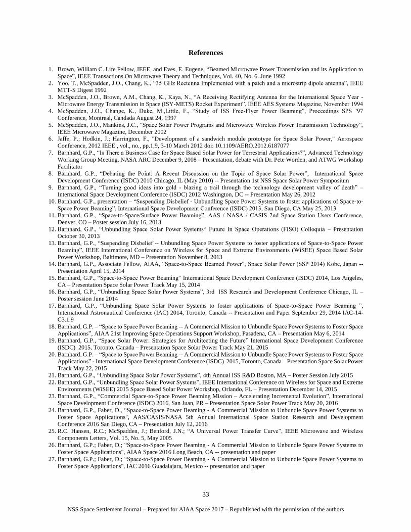
It is useful to note as shown in Table 5 -- Comparing Beaming Power Density and the Solar Constant, Isc =
Solar Constant at 1 AU = 0.1367 W/cm2 is approximately an order of magnitude less than pd for Case 3 Table 4: W
Band Target 95 GHz pd with 𝑃𝑡 = 6000 W and 𝐴𝑡 = 10000 cm2. While the calculated values show real promise more
rigorous analysis and testing to identify, better characterize, and optimize the efficiency of all elements of end-to-end
radiant energy beaming systems is required. Furthermore, the projected conversion efficiency from microwave to DC
power (e.g., 85-92% efficient, circa 1992) is significantly greater than the efficiency of even the most advanced solar
photovoltaic cells (e.g., less than 46.0%) Accordingly, from the assessments and calculations done to date it can be
deduced that there is a reasonable to high likelihood given an optimized radiant energy beam transmitter that there is
significant margin in the application trade space for space-to-space power beaming to warrant being considered as a
mission enhancing if not mission enabling resource.
One example worth examining is how the possible extension of the useful mission life of proposed NASA
Resource Prospector mission from 14 days through a succession of lunar day night cycles would amplify its economic
and scientific value. This could be a specific objective of a trade study to determine if Resource Prospector (or an
evolved successor) with the potential of providing long duration assays of the lunar surface region are practical and
cost effective means of buying down the investment risk of lunar volatiles mining. Understanding the engineering
requirements of both the ground unit as well as an orbiting satellite transmitter would move the conversation about
cost feasible applications forward.
H. Technology Development
For the purposes of this work we have defined the scope of the technology development involved to include:
1) Knowledge Base on Radiant Energy Beaming
a. Significant Actors/Interested Entities
b. Intellectual Commons
c. Prior Art
i. Patents & Patents Pending
ii. Trade Secrets
d. Known Unknowns
2) End-to-End State Models
a. Unbundled Electrical Power System
i. Characterize the radiant energy beam in a near realtime state model
Pd Pd Pd
Case 1 @26.5 GHz Case 2 @36 GHz Case 3 @95 GHz
Table 1. Power Density with D=200 m, Pt= 3000 W and At = 1642 cm20.00964 0.01774 0.12331
Table 2. Power Density with D=200 m, Pt= 6000 W and At = 1642 cm20.01929 0.03549 0.24661
Table 3. Power Density with D=200 m, Pt= 3000 W and At = 10000 cm20.05874 0.10809 0.75108
Table 4. Power Density with D=200 m, Pt= 6000 W and At = 10000 cm20.11747 0.21617 1.50216
Table 5. Comparing Beaming Power Density and the Solar Constant
I sc = Solar Constant at 1 AU = 0.1367 Watts/cm2
Power Density
(Watts/cm2)
Power Density
(Watts/cm2)
Power Density
(Watts/cm2)
Pd significantly lower than Isc
Pd similar to Isc
Pd significantly higher than Isc
NSS Space Settlement Journal – Prepared for AIAA Space 2017 – Republished with the permission of the authors
27
ii. Optimize the radiant energy beam for performance based on application
iii. Operationalize the radiant energy beam by defining and encoding the performance envelope and
operating rules.
b. Spacecraft Systems-of-Systems
i. Mission operations control
3) Beam Sources
a. Frequency Optimization
i. 26.5 GHz (Ka Band Low)
ii. 36 GHz (Ka Band Target)
iii. 95 GHz (W Band Target)
iv. Higher Frequencies up through Optical
b. Power levels
c. Human effects
d. Electomagnetic effects
4) Rectennas
a. Rectenna Areas
i. 100 cm2 (1 U) to 1 m2 (100 U)
b. Rectenna Types
i. 2D Rectangular, Polarized Spiral, Fractal, etc.
ii. 3D Pyramid, Conical, Fractal, etc.
iii. Reflectarray and photovoltaic combinations
c. Build Options
i. Earth manufactured, deployed on-orbit
ii. Earth manufactured, assembled on-orbit
iii. 3D Printed on-orbit
5) Flight Test Articles
a. DSI (3U) Spacecraft
b. Alpha CubeSat (6U) Spacecraft
6) Flight Support Equipment
a. Trajectory Insertion Bus
b. Spacecraft Deployment Flight Support Equipment
c. Spacecraft Recovery Flight Support Equipment
I. Technology Demonstration
For the purposes of this work we have defined the scope of the technology demonstation involved to include:
1) Radiant Energy Beam Management
a. Characterization of the radiant energy beam
b. Optimization of the radiant energy beam
c. Operationalize the radiant energy beam
2) Test Beds
a. Near Field/Far Field Test Bed
b. Loosely Coupled Modular Structures Test Bed
c. Propulsion Augment Test Bed
d. Platform Infrastructure Technology Test Bed
3) Rectennas
a. Differentiation and performance characterization by size
b. Differentiation and performance characterization by type
c. Differentiation and performance characterization by build method
4) Flight Test Article & Flight Support Equipment Interfaces
a. Modular Small Space Craft (e.g., DSI (3U), Alpha CubeSat (6U), etc.) Interfaces
b. Trajectory Insertion Bus Interfaces
c. Spacecraft Deployment Interfaces
d. Spacecraft Recovery Interfaces
e. Logistics Carrier Augmentation Interfaces
J. Technology Deployment
NSS Space Settlement Journal – Prepared for AIAA Space 2017 – Republished with the permission of the authors
28
For the purposes of this work we have defined the scope of the technology deployment involved to include:
1) Asteroidal Assay Mission – The mission objective is to support landed and/or near surface grazing orbiting
sensors for asteroid assay work that can be powered by a radiant energy beam from some number of co-
orbiting motherships.
2) Co-orbiting Manufacturing Cell Mission – The mission objective is to support the use of one or more ISS
logistics carriers as crew tended co-orbiting free flyers for some number of cycles to accommodate
manufacturing cells which require more stringent microgravity and/or safety considerations.
3) Beyond Earth Orbit Deployment Platform – The mission objective is to support the use of one or more ISS
trajectory insertion bus by directly or indirectly providing a propulsion augment using a radiant energy beam
from the ISS.
K. Tetrahedral Target & Formation
For the purposes of this work we have selected a tetrahedral target formation based on the following rationale:
1) A tetrahedron is the most fundamental locked 3 dimensional structure.
2) A tetrahedron formation through triangulation readily allows for both a fixed local position/orientation frame
of reference as well as reconciliation to any required external frame of reference.
3) The tetrahedron is applicable to both individual physical targets and formations.
Both target and formation scale factors must be experimentally determined based on the sensible combination of
far field and near field effects observed. It is anticipated that the combination of known formation geometry and the
measurable differential response of rectenna elements will allow for very precise local position/orientation
management.
IV. Technological Challenges
The first principles physics of both “near field” and “far field” energy effects are considered well understood.
However, the use of radiant energy (by definition a far field effect, a.k.a. “Beaming”) to transfer (power, data, force,
heat) on an optimized basis (particularly at far field-near field boundaries) either directly and/or by inducing near field
effects at a distance is less understood at least from the stand point of practical applications. Accordingly, this is
applied engineering work, (a.k.a. technology development), not new physics.
To optimize beaming applications we need to better understand how each of the components of radiant energy can
be made to interact in a controlled manner.
A. Radiant Energy Beam Components
For the purposes of this work we have defined the radiant energy beam components to include:
1) Electrical
2) Magnetic
3) Linear & Angular Momentum
4) Thermal
5) Data
There are potential direct and indirect uses for each beam component. Use of any combination of these components
has implications for all spacecraft systems (e.g., power, data, thermal, communications, navigation, structures, GN&C,
propulsion, payloads, etc.).
In theory, the use of the component interactions can enable:
1) Individual knowledge of position and orientation
2) Shared knowledge loose coupling /interfaces between related objects
3) Near network control (size to sense/proportionality to enable desired control)
4) Fixed and/or rotating beam projections
5) Potential for net velocity along any specified vector
V. Mission Team
The following organizations, entities, and/or individuals have notified XISP-Inc of their interest in
cooperation/collaboration with respect to this mission:
A. Commercial Entities
NSS Space Settlement Journal – Prepared for AIAA Space 2017 – Republished with the permission of the authors
29
1) Xtraordinary Innovative Space Partnerships, Inc. - Gary Barnhard, et al.
2) Barnhard Associates, LLC - Gary Barnhard, et al.
3) Raytheon, Inc. – Hooman Kazemi, et al.
4) OrbitalATK – Bob Richards, et al.
5) Immortal Data Inc. – Dale Amon, et al.
6) Deep Space Industries, Inc - Peter Stibrany, et al.
7) Center for the Advancement of Science In Space (CASIS) – Jennifer Lopez, et al.
8) Nanoracks Inc. – Chad Brinkley, et al.
9) Made In Space, Inc. – Jason Dunn, et al.
10) EXOS Aerospace & Technologies, Inc. – John Quinn, et al.
11) Tethers Unlimited, Inc. – Rob Hoyt, et al.
12) Power Correction System, Inc – Brahm Segal, et.al
B. Universities:
1) University of New Mexico Configurable Space Microsystems Innovations and Applications Center
(COSMIAC) - Christos Christodoulou, et al.
2) University of Maryland Space Systems Lab – David Akin, et.al
3) MIT Space Systems Lab – Alvar Saenz-Otero, et al.
4) University of North Dakota Space Systems Lab – Sima Noghanian, et al.
5) Saint Louis University Space Systems Lab – Michael Swartwout, et al.
C. Government Agencies:
1) NASA Headquarters Human Exploration & Operations Mission Directorate
a. Advanced Exploration Systems Division, Jason Crusan, et al.
b. Space Communications and Navigation Office, Jim Schier, et al.
2) Multiple NASA Centers will have some cooperating role – NASA ARC, et al.
3) U.S. Naval Research Lab – Paul Jaffe, et.al
D. Non-profit Organizations:
1) Space Development Foundation – David Dunlop, et al.
2) SPACECanada – George Dietrich, et al.
3) National Space Society
Multiple other commercial, educational, non-profit organizations, and ISS International Partners have expressed
substantive interest in cooperation/collaboration with respect to this mission and are actively negotiating their potential
role with XISP-Inc.
The XISP-Inc core team consists of:
• Gary Pearce Barnhard – Computer/Robotic/Space Systems Engineer, Space Solar Power technology/mission
development, research work on the applications of knowledge based systems to the domain space systems
engineering, research work on near real-time state models, research work on management operations control
applications including process flow engineering problems, responsible for the ISS Robotic Systems
Integration Standards (RSIS) development, responsible for the ISS external utility port standardization effort,
responsible for the ISS system level requirements for advanced automation and robotics.
• Daniel Ray Faber – Spacecraft systems/subsystems systems engineering and development, transmitter and
receiver development.
• John Mankins – Former NASA Headquarters Technology Development portfolio lead, Space Solar Power
technology development and demonstration.
• Paul Werbos – former NSF program director for energy, intelligent systems, and modeling for electronic
systems and devices. Lead director for the last actual NSF funding initiative in
https://nsf.gov/pubs/2002/nsf02098/nsf02098.pdf Space Solar Power technology development and
demonstration.
• Seth Potter – Space Systems Engineer, Space Solar Power technology development, demonstration, and
deployment, Beam forming.
• Paul Jaffe – Space Solar Power technology development and demonstration.
• James McSpadden – Microwave systems engineer.
NSS Space Settlement Journal – Prepared for AIAA Space 2017 – Republished with the permission of the authors
It is anticipated that the combination of the revenue from the power and ancillary services provided to ISS co-
orbiting/LEO customers and the value of the perceived and/or real cost, schedule, and technical risks retired by the
TD3 mission will realize a large enough return to secure the follow-on investment required to build out the Lunar
Power& Light Company.
XISP-Inc is part of the ULA sponsored Cislunar Marketplace development effort involving over 150 entities.
There is an open market for degrading legacy systems in the near-term, an evolving market for new enhanced
satellites in the mid-term (~2 to ~5 years) , and an essential element of “immortal” serviced platform systems that
will be designed to accommodate multiple generations of payloads in the long-term (~5 to ~10 years). Any
enhanced electrical power and ancillary services made available on an in situ and/or beamed basis to customers will
be reflected directly as an increased ROI even after accounting for the recurring costs.
Any electrical power and allied utility services made available would prove to be mission enhancing if not
mission enabling and has the potential for creating a reoccurring revenue stream.
The ability to augment available electrical power and/or transfer heat via a radiant energy beam can significant
improve the performance of electrical as well as chemical propulsion systems (e.g., resistojets, etc.). Applications
include orbital altitude and plane change, Cislunar and deep space trajectory insertion, as well as cycling transfers.
The combination of the XISP-Inc Alpha Cube Sat (ACS), SSPB, Interoperable Network Communication
Architectures (INCA), Management Operations Control Applications (MOCA) and Halfway To Anywhere (HTA)
missions serve as a resource for fostering the development of Cislunar utilities across the range of addressable
markets as shown in Figure 2 – XISP-Inc Commercial Mission Set Venn Diagram. The combination of line-of-site
high frequency microwave/laser transmission from lunar resonant ground tracking orbits which are long term stable
with exceptionally close surface approach as well as surface mounted relay and proximity distribution systems can
provide a range of power and allied utility service options for lunar facilities and related operations. ESA, JAXA,
and NASA SCaN representatives have shown interest in understanding these options.
NSS Space Settlement Journal – Prepared for AIAA Space 2017 – Republished with the permission of the authors
31
ACS provides a technology development, demonstration, and deployment (TD3) spacecraft bus for HTA, INCA, MOCA, and SSPB Low cost configurable spacecraft for Earth facing, Cislunar infrastructure, and beyond Earth orbit applications.
HTA provides TD3 propulsion testbed, trajectory insertion bus, alternate minimum energy trajectories, and resonance orbits for ACS, INCA, MOCA and SSPB.ISS as a transportation node for low cost, readily deployable Earth orbit, cislunar and beyond Earth orbit mission support.
INCA provides TD3 web accelerator, QoS routing/pervasively networked gateway, multi-core thermally managed computer resources, Xrosslink protocol, relay interface kits, for ACS, HTA, MOCA, and SSPB Communications & Navigation Utilities and interface kits for Earth facing, on-orbit, and space facing mission support/
networks. MOCA provides TD3 near realtime state models, mutable locus of control, and virtual operations center for ACS, HTA, INCA, and SSPB
Facilitate crewed, tele-operated/shared control, and autonomous in situ operations reducing crew time required for experiments and increasing ISS productivity. SSPB provides TD3 radiant energy beaming testbed, and electrical utilities for ACS, HTA, INCA, and MOCA
Space-to-Space and Space-to-Alternate surface electrical utilities.
MOCA
XISP-Inc Commercial Mission Set
HTA
ACS
SSPB INCA
Alpha CubeSat (ACS)
Space-to-Space Power Beaming (SSPB)
Halfway To Anywhere (HTA)
Interoperable Network Communication
Architecture (INCA)
Mission Operations Control Applications
(MOCA)
Figure 2. XISP-Inc Commercial Mission Set Venn Diagram
ACS illustrates the potential for cost effective long duration networks with short transmission distances and
relatively low power requirements. Enhanced ACS like systems could illustrate the potential for laser power beaming
with short transmission distances to transmit stay alive power to many points on the lunar surface.
The ISS testbed portion of the TD3 mission results in terms of characterization, optimization, and operational rules
as well as the resulting tested system data regarding distance, power and frequencies can be practically related to
systems which could provide stay alive power on the lunar surface during the lunar night. It is anticipated that by
projecting how much power and how often it could be provided during a 14 day lunar night we could foster the creation
of market demand, for example in North and or South polar target areas.
Potential lunar surface customers include:
o Resource Prospector successor
o International Lunar Network locations
o Mobile surface rovers for long duration travel: Schroedinger Crater missions proposed by Kring et.al.
o ESA proposed Moon Village
XISP-Inc anticipated that there is a market for ancillary services (communications, data, navigation/time) and
strategies for achieving an Interoperable Network Communication Architecture (INCA) as well as the Quality of
Service (QoS) requirements (i.e., performance, availability, and security)
Frequency agnostic (e.g., Software Defined Radios, electro/optical converged electronics, and selectable apertures)
pervasively networked communications and data systems with provisions for Delay and Disturbance Tolerant
Networking (DTN) including store and forward capacity, and QoS based routing will likely be essential.
NSS Space Settlement Journal – Prepared for AIAA Space 2017 – Republished with the permission of the authors
32
It is incumbent on XISP-Inc to establish the commercial merits of the Lunar Power & Light Company as a
Public/Private Partnership opportunity worthy of NASA, International, and commercial partner participation.
The near term ISS TD3 mission incorporating frequency agnostic (Ka band optical beaming) technology is a
precursor for lunar addressable markets.
Beam pointing and targeting from an orbiting spacecraft to another target may be facilitated by low power RF,
microwave, and/or laser guide beams.
A high value application of the SSPB ISS testbed is to prove out the utility of as well as reduce the cost,
schedule, and technical risks associated with the asteroidal assay missions. The concept is that such missions will
require one or more asteroid co-orbiting motherships which fractionate to deliver landed sensors packages that are
provided power and allied utility services by radiant energy beaming.
Parallel work in sourcing power generation system alternatives including photovoltaic, solar concentrator, solar
dynamic, and solar pumped lasers is essential to realizing the potential of a Cislunar electrical and ancillary services
company (aka. Lunar Power & Light Company) and is now underway.
Opportunities for international cooperation leveraging the ISS Intergovernmental Agreements are being explored
and developed. Use of ISS helps ensure that this is an international cooperative/collaborative TD3 mission that
moves forward in a transparent and well understood manner by the international community.
VII. Conclusion
Successful demonstration of space solar power beaming helps pave the way for its use in a range of space-to-space,
space-to-lunar/infrastructure surface, and space-to-Earth applications by reducing the perceived cost, schedule, and
technical risk of the technology.
Commercial space applications include mission enhancing and/or mission enabling expansion of operational
mission time/capabilities, enhanced spacecraft/infrastructure design flexibility as well as out-bound orbital trajectory
insertion propulsion.
Orchestraing the TD3 mission to ensure that it is driven by what is required to meet commercial customer
requirements necessitates a frequency agnostic approach to system engineering. Accordingly, technology
development “push” is insufficient, mission requirements “pull” is essential to ensuring that actually meeting customer
requirements is not lost in the process.
In theory, there is no difference between theory and practice – but in practice, there is.
– Jan L.A. van de Snepscheut, computer scientist
Acknowledgements
This XISP-Inc work has been and continues to be sponsored by Barnhard Associates, LLC (BALLC) / Xisp.net.
This builds on original work by William Brown, BALLC internal research and development work performed by the
principal author of this paper, as well as mission development support by the listed participants in the SSPB Mission
Team. The assistance of James McSpadden and Avram Bar-Cohen as technical peer reviewers is gratefully
acknowledged.
NSS Space Settlement Journal – Prepared for AIAA Space 2017 – Republished with the permission of the authors
33
References
1. Brown, William C. Life Fellow, IEEE, and Eves, E. Eugene, “Beamed Microwave Power Transmission and its Application to
Space”, IEEE Transactions On Microwave Theory and Techniques, Vol. 40, No. 6. June 1992
2. Yoo, T., McSpadden, J.O., Chang, K., “35 GHz Rectenna Implemented with a patch and a microstrip dipole antenna”, IEEE
MTT-S Digest 1992
3. McSpadden, J.O., Brown, A.M., Chang, K., Kaya, N., “A Receiving Rectifying Antenna for the International Space Year -
Microwave Energy Transmission in Space (ISY-METS) Rocket Experiment”, IEEE AES Systems Magazine, November 1994
4. McSpadden, J.O., Change, K., Duke, M.,Little, F., “Study of ISS Free-Flyer Power Beaming”, Proceedings SPS ’97
Conference, Montreal, Candada August 24, 1997
5. McSpadden, J.O., Mankins, J.C., “Space Solar Power Programs and Microwave Wireless Power Transmission Technology”,
IEEE Microwave Magazine, December 2002
6. Jaffe, P.; Hodkin, J.; Harrington, F., "Development of a sandwich module prototype for Space Solar Power," Aerospace