Aeolianvibrations Galloping Oscillations of bundled
conductors
Spacers
MOSDORFER Ges. m. b. H. A-8160 WEIZTel. 0 31 72 / 25 0 50, Fax 0 31 72 / 25 05 29, e-mail: [email protected]/2
SPACER DAMPERSGENERAL Wind induced vibrations on high voltage overhead lines can be categorised
according to their induced frequencies as follows: High frequency vibration(Karman or aeolian vibrations ), low-frequency oscillations (conductor gallo-ping) and subspan oscillations or bundle conductor oscillations.
Four kinds of subspan oscillations exist, three forms of rigid body modes andthe most dangerous so called subconductor oscillation. Most reports of sub-conductor vibrations pertain to lines located in terrain that is either generallyflat or gently rolling. There is a minimum, or threshold, wind velocity ( approx4 m/s) and a certain inclination of the conductors required to initiate motion.The oscillations of the leeward conductor are self-induced, where the energyinput of the wind will be dissipated by the conductor. The frequencies appea-ring here are lower than 5 Hz and the amplitudes could reach a value whichwill lead to clashing of the conductors.
constant
4–18 m/s
0.15–3 (10) Hz
Subconductor vibrationsup to 50 cm
Fixed vibration rangeup to 2 m
Distance of thesubconductors
Inclination of the conductorsPositioning of the conductors
9/3MOSDORFER Ges. m. b. H. A-8160 WEIZTel. 0 31 72 / 25 0 50, Fax 0 31 72 / 25 05 29, e-mail: [email protected]
Design and functionSpacer dampers consist of clamps, a connec-ting frame and the damping elements. Thedamping elements, which are made of highlyflexible macromolecular elastomere, guaran-tee a certain mobility of the damper clamp.Additionally the damping elements are desi-gned in respect of temperature resistance, en-vironmental conditions and to be free of coro-na.All types of spacers have passed strict typetests in order to guarantee suitability.
Computer programmeHigh-frequency vibrationsThe maximum bending strain at different fre-quencies, at the suspension point of the con-ductor or at the clamping area of the spacers,with various configurations of conductorbundles, with or without vibration damperscan be calculated with a special computerprogramme.As well as parameters of the spacer damperscapability established in the laboratory, lineparameters supplied by the customer are alsotaken into account in the computer program-me.
Subconductor oscillationsTo give an answer about the damper to aspecific configuration of a conductor bundle,the characteristics of such a configuration willbe simulated by an analytical model. All pa-rameters of the spacer dampers, their locati-on, the movements of the conductor bundlecaused by wind as well as conductor tensilestresses will be taken into consideration.This calculation gives information about thecritical wind velocity and reflects a factor toestimate the probability that subconductor vi-brations will occur.
Placement of the damping elements.
Example of a study of sub span oscillation.
Maximum bending strain of conductors and spacers.
Maximum span length: 80 m
Wind velocity [m/s] Tilt [Grad]
Insta
bilit
y
Twin bundle
Vibration study for bundle conductorsMaximum bending strains
Code Nr.Client: MosdorferProject: TestConductor:ALAW253/23Diameter: 21,70 mmTension: 15000 N
• with flexible copper bond L.-Nr. …e. g.: 4983.51/40Clamp designs:
L-Nr. are valid for standard clamps.
Standard
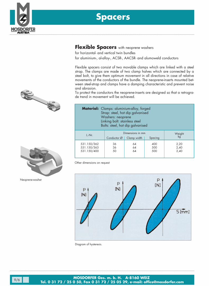
Material: Clamps: aluminium-alloy, forgedInserts: neopreneBolts: steel, hot dip galvanised
L.-Nr. Weightkg
Spacers
9/5MOSDORFER Ges. m. b. H. A-8160 WEIZTel. 0 31 72 / 25 0 50, Fax 0 31 72 / 25 05 29, e-mail: [email protected]
Conductor Ø Width of clamp Spacing
Dimensions in mm
SPACERSSemi-flexible spacerswith neoprene inserts
for horizontal and vertical twin bundlesfor aluminium-, al-alloy-, ACSR-, AACSR- and alumoweld conductors
Semi-flexible spacers consist of two clamp halves with a semi-conducting neo-prene-insert, which is solidly connected with the clamp halves. They have nomovable components, which means that there will be no damage caused byabrasion. Movements within the conductor bundle will be absorbed by theneoprene-inserts. They also act as protection for the conductor.The design of connection guarantees easy and cost-effective installation.
Spacers for four-bundleSerial-Nr. 4977…L.-Nr. on request
Spacers for triple-bundleSerial-Nr. 4977…L.-Nr. on request
Material: Clamps: aluminium-alloy, forgedStrap: steel, hot dip galvanisedWashers: neopreneLinking bolt: stainless steelBolts: steel, hot dip galvanised
L.-Nr. Weightkg
Spacers
MOSDORFER Ges. m. b. H. A-8160 WEIZTel. 0 31 72 / 25 0 50, Fax 0 31 72 / 25 05 29, e-mail: [email protected]/6
Flexible Spacers with neoprene washersfor horizontal- and vertical twin bundlesfor aluminium-, al-alloy-, ACSR-, AACSR- and alumoweld conductors
Flexible spacers consist of two movable clamps which are linked with a steelstrap. The clamps are made of two clamp halves which are connected by asteel bolt, to give them optimum movement in all directions in case of relativemovements of the conductors of the bundle. The neoprene-inserts mounted bet-ween steel-strap and clamps have a damping characteristic and prevent noiseand abrasion.To protect the conductors the neoprene-inserts are designed so that a retrogra-de trend in movement will be achieved.
9/7MOSDORFER Ges. m. b. H. A-8160 WEIZTel. 0 31 72 / 25 0 50, Fax 0 31 72 / 25 05 29, e-mail: [email protected]
0,920,920,930,930,93
Flexible Spacers, with messenger wire and reinforcing sleevefor horizontal twin bundlefor aluminium-, al-alloy-, ACSR-, AACSR- and alumoweld conductors
This spacer works because of the special messenger cable which connects thetwo clamping bodies.These clamping bodies have a special shape to prevent damage of the con-ductor. The messenger cable allows a certain flexibility in all directions, whichis limited by a longer or shorter sleeve, which is compressed onto the messen-ger cable.
MOSDORFER Ges. m. b. H. A-8160 WEIZTel. 0 31 72 / 25 0 50, Fax 0 31 72 / 25 05 29, e-mail: [email protected]/8
454550
0,901,001,10
Flexible spacers patented, with strapsfor horizontal and vertical twin bundlesfor aluminium-, al-alloy-, ACSR-, AACSR- and alumoweld conductors
This type of spacer connects the two clamp bodies by means of a strap and aconnecting bolt this allows a possible displacement in the longitudinal direc-tion.The bore holes in the straps are fitted with stainless steel bushings thus limitingthe abrasion.The shape of the distance strap can be round or flat.
531.65/381531.65/3B1531.65/709
Conductor Ø
18,8–19,921,7–22,526,1–27,5
Clamp width Spacing
400400400
Type of strap
flatflat
round
Other dimensions on request.
Dimensions in mm
Flexible Spacers with al-strapsfor horizontal and vertical twin bundlesfor aluminium-, al-alloy-, ACSR-, AACSR- and alumoweld conductors
Serial-Nr. 9437This type connects the two clamp bodies by means of a strap and a connectingbolt also this allows a possible displacement in the longitudinal direction.To reduce possible noise caused by the link and connencting bolts (rattle) thebore holes are finished by reaming.
Serial-Nr. 9438Similar to Serial-Nr. 9437 but with neoprene-bushings.
94379438
21,0 – 32,821,0 – 36,0
4545
200–400200–400
1,001,00
Conductor Ø Clamp width Spacing
Other dimensions and types with stainless steel bolts on request.
Dimensions in mm
Spacers
9/9MOSDORFER Ges. m. b. H. A-8160 WEIZTel. 0 31 72 / 25 0 50, Fax 0 31 72 / 25 05 29, e-mail: [email protected]
Semi-flexible Spacersfor horizontal and vertical twin bundlesfor aluminium-, al-alloy-, ACSR-, AACSR- and alumoweld conductorsSemi-flexible spacers consist of two clamp halves with a semi-conducting neo-prene-insert, which is solidly connected between the clamp halves. There areno movable components, which means that there will be no damage causedby abrasion. Movements within the conductor bundle will be absorbed by theneoprene-inserts. They also act as protection for the conductor.The design of the connection guarantees easy and cost-effective installation.
Material: Clamp-body: cast aluminium-alloyInsert: neopreneBolts: steel, hot dip galvanized
Serial-Nr. 4974…L.-Nr. on request.
Rigid spacers for jumper connectionsdimensions on request.