Page 1
American Institute of Aeronautics and Astronautics
1
SpaceX Dragon Air Circulation System
Brenda J. Hernandez1 and Siarhei Piatrovich
2
Space Exploration Technologies, Hawthorne, CA, 90250
Mauro Prina3
Space Exploration Technologies, Hawthorne, CA, 90250
The Dragon capsule is a reusable vehicle being developed by Space Exploration
Technologies (SpaceX) that will provide commercial cargo transportation to the
International Space Station (ISS). Dragon is designed to be a habitable module while it is
berthed to ISS. As such, the Dragon Environmental Control System (ECS) consists of
pressure control and pressure equalization, air sampling, fire detection, illumination, and an
air circulation system. The air circulation system prevents pockets of stagnant air in Dragon
that can be hazardous to the ISS crew. In addition, through the inter-module duct, the air
circulation system provides fresh air from ISS into Dragon. To utilize the maximum volume
of Dragon for cargo packaging, the Dragon ECS air circulation system is designed around
cargo rack optimization. At the same time, the air circulation system is designed to meet the
National Aeronautics Space Administration (NASA) inter-module and intra-module
ventilation requirements and acoustic requirements. A flight like configuration of the
Dragon capsule including the air circulation system was recently assembled for testing to
assess the design for inter-module and intra-module ventilation and acoustics. The testing
included the Dragon capsule, and flight configuration in the pressure section with cargo
racks, lockers, all of the air circulation components, and acoustic treatment. The air
circulation test was also used to verify the Computational Fluid Dynamics (CFD) model of
the Dragon capsule. The CFD model included the same Dragon internal geometry that was
assembled for the test. This paper will describe the Dragon air circulation system design
which has been verified by testing the system and with CFD analysis.
Nomenclature
ECS = Environmental Control System
ISS = International Space Station
CFD = Computational Fluid Dynamics
COTS = Commercial Orbital Transportation Services
TPS = Thermal Protection System
IMV = Inter-Module Ventilation Duct
SPL = Sound Pressure Limit
NC = Noise Criterion
PFE = Portable Fire Extinguisher
1 ECS Environmental Control System Engineer, Thermal, 1 Rocket Road Hawthorn, CA, and AIAA Member Grade
for first author. 2 Environmental Control System Engineer, Thermal, 1 Rocket Road Hawthorn, CA, and AIAA Member Grade for
second author. 3 Thermal Dynamics Manager, 1 Rocket Road Hawthorn, CA, and AIAA Member Grade for third author.
https://ntrs.nasa.gov/search.jsp?R=20110014250 2018-05-24T20:02:05+00:00Z
Page 2
American Institute of Aeronautics and Astronautics
2
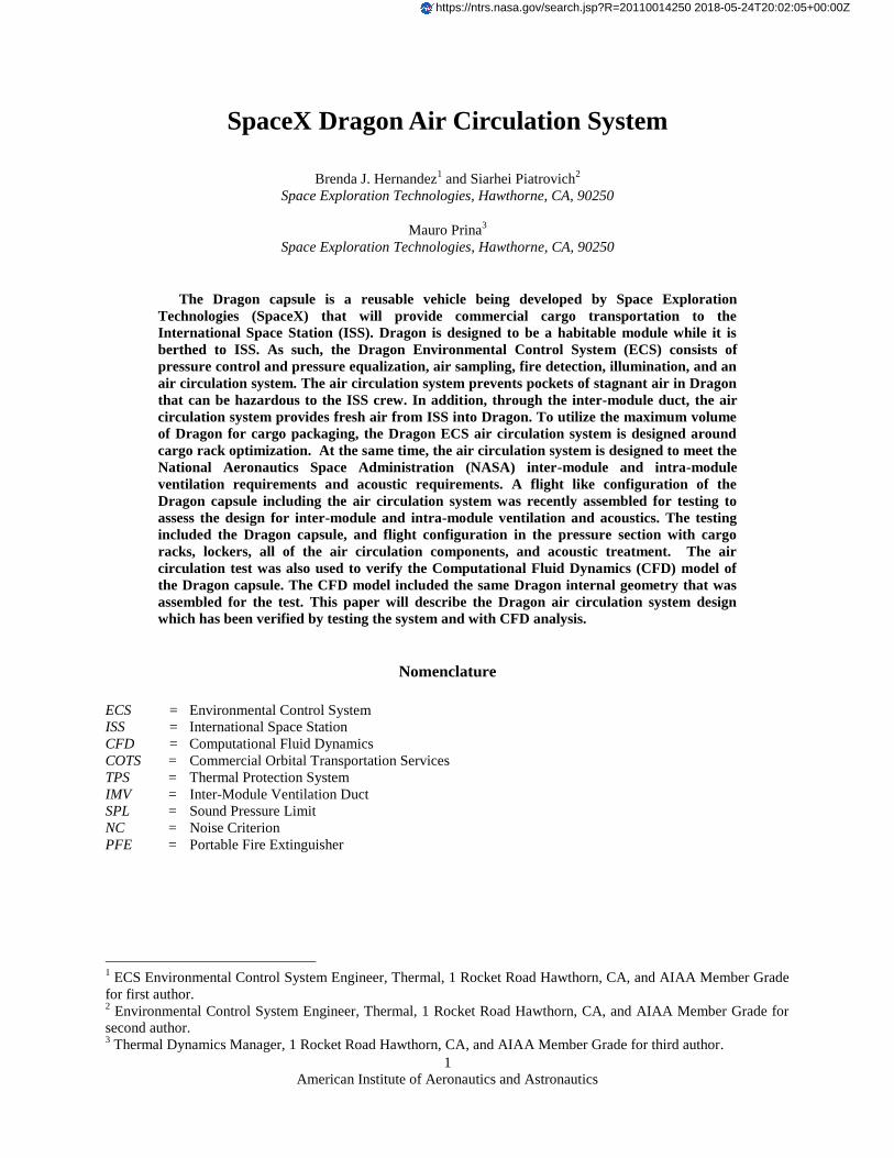
I. Introduction
ragon is a commercially developed reusable capsule developed by
SpaceX under NASA’s Commercial Orbital Transportation Services
(COTS) to deliver cargo to and from the International Space Station. Dragon
consists of a capsule with pressurized section and an unpressurized service
section for cargo and avionics, a trunk with a radiator and deploying solar
array, and a nose cone to protect the ISS berthing ring during ascent. Figure 1
shows the 1st demonstration Dragon that flew in a low Earth orbit in
December 2010. The service section has the Dragon propulsion system and
avionics. The pressurized section contains avionics boxes, powered cargo and
unpowered cargo. The entire pressure section and service section is covered
with thermal protection system (TPS) for insulation. The Dragon air
circulation system includes a fan, ducting, inlet and outlet vents, air to liquid
heat exchanger, accommodation for powered cargo and smoke detectors.
Additionally, the air circulation system was designed with consideration for
noise and includes acoustic treatment to reduce air borne noise. The air
circulation system test and CFD correlation and the acoustics testing are
discussed herein.
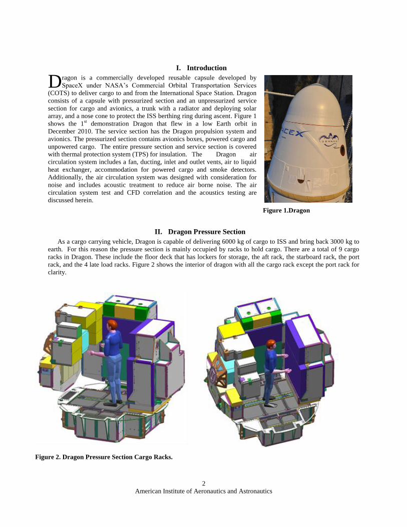
II. Dragon Pressure Section
As a cargo carrying vehicle, Dragon is capable of delivering 6000 kg of cargo to ISS and bring back 3000 kg to
earth. For this reason the pressure section is mainly occupied by racks to hold cargo. There are a total of 9 cargo
racks in Dragon. These include the floor deck that has lockers for storage, the aft rack, the starboard rack, the port
rack, and the 4 late load racks. Figure 2 shows the interior of dragon with all the cargo rack except the port rack for
clarity.
D
Figure 1.Dragon
Figure 2. Dragon Pressure Section Cargo Racks.
Page 3
American Institute of Aeronautics and Astronautics
3
As is seen from figure 2, it is necessary to have an air circulation system that not only meets all the necessary
requirements, but is also capable of providing enough pressure given the allotted volume for the air duct and in
consideration of the fact that the capsule will be filled with avionics boxes, cargo and cargo racks that constrain air
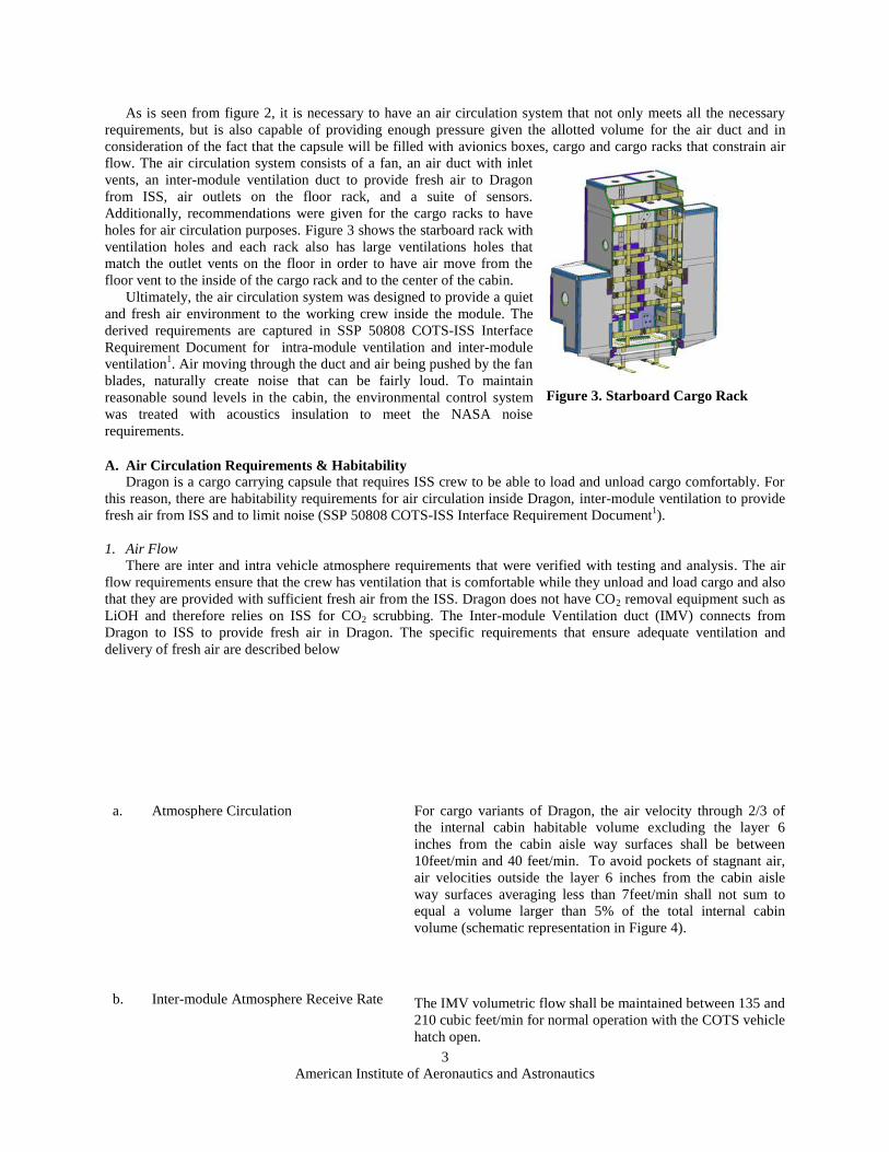
flow. The air circulation system consists of a fan, an air duct with inlet
vents, an inter-module ventilation duct to provide fresh air to Dragon
from ISS, air outlets on the floor rack, and a suite of sensors.
Additionally, recommendations were given for the cargo racks to have
holes for air circulation purposes. Figure 3 shows the starboard rack with
ventilation holes and each rack also has large ventilations holes that
match the outlet vents on the floor in order to have air move from the
floor vent to the inside of the cargo rack and to the center of the cabin.
Ultimately, the air circulation system was designed to provide a quiet
and fresh air environment to the working crew inside the module. The
derived requirements are captured in SSP 50808 COTS-ISS Interface
Requirement Document for intra-module ventilation and inter-module
ventilation1. Air moving through the duct and air being pushed by the fan
blades, naturally create noise that can be fairly loud. To maintain
reasonable sound levels in the cabin, the environmental control system
was treated with acoustics insulation to meet the NASA noise
requirements.
A. Air Circulation Requirements & Habitability
Dragon is a cargo carrying capsule that requires ISS crew to be able to load and unload cargo comfortably. For
this reason, there are habitability requirements for air circulation inside Dragon, inter-module ventilation to provide
fresh air from ISS and to limit noise (SSP 50808 COTS-ISS Interface Requirement Document1).
1. Air Flow
There are inter and intra vehicle atmosphere requirements that were verified with testing and analysis. The air
flow requirements ensure that the crew has ventilation that is comfortable while they unload and load cargo and also
that they are provided with sufficient fresh air from the ISS. Dragon does not have CO2 removal equipment such as
LiOH and therefore relies on ISS for CO2 scrubbing. The Inter-module Ventilation duct (IMV) connects from
Dragon to ISS to provide fresh air in Dragon. The specific requirements that ensure adequate ventilation and
delivery of fresh air are described below
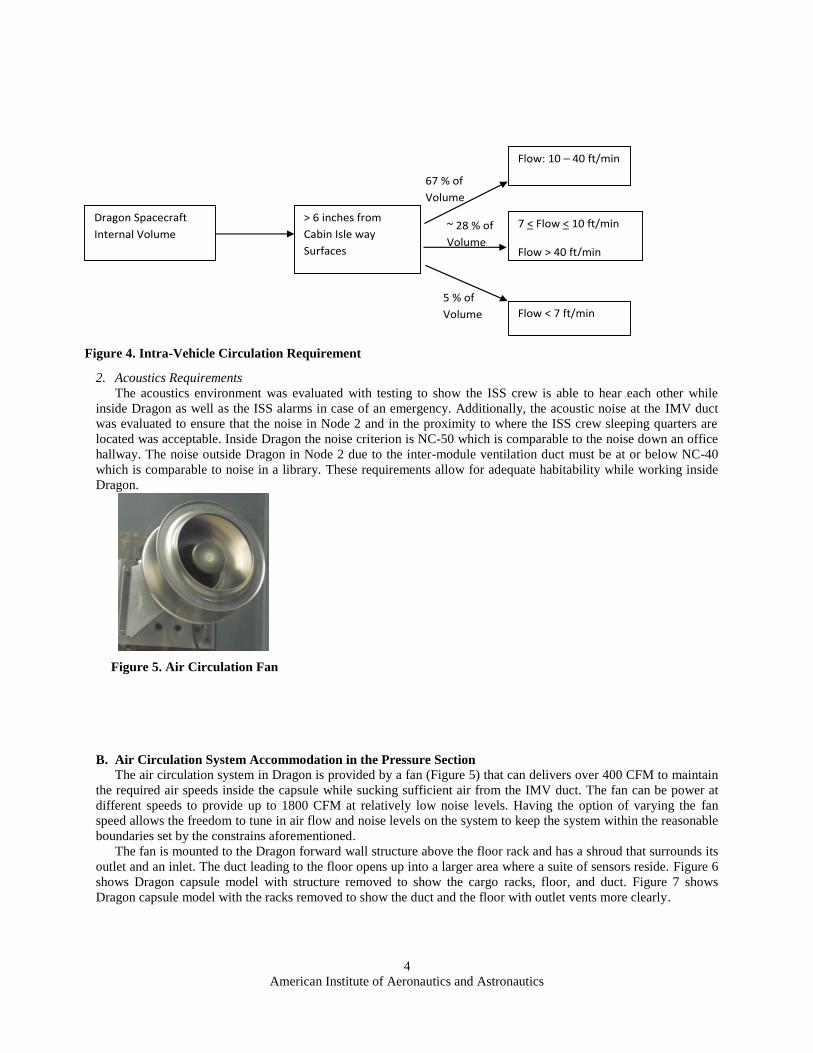
a. Atmosphere Circulation For cargo variants of Dragon, the air velocity through 2/3 of
the internal cabin habitable volume excluding the layer 6
inches from the cabin aisle way surfaces shall be between
10feet/min and 40 feet/min. To avoid pockets of stagnant air,
air velocities outside the layer 6 inches from the cabin aisle
way surfaces averaging less than 7feet/min shall not sum to
equal a volume larger than 5% of the total internal cabin
volume (schematic representation in Figure 4).
b. Inter-module Atmosphere Receive Rate The IMV volumetric flow shall be maintained between 135 and
210 cubic feet/min for normal operation with the COTS vehicle
hatch open.
Figure 3. Starboard Cargo Rack
Page 4
American Institute of Aeronautics and Astronautics
4
2. Acoustics Requirements
The acoustics environment was evaluated with testing to show the ISS crew is able to hear each other while
inside Dragon as well as the ISS alarms in case of an emergency. Additionally, the acoustic noise at the IMV duct
was evaluated to ensure that the noise in Node 2 and in the proximity to where the ISS crew sleeping quarters are
located was acceptable. Inside Dragon the noise criterion is NC-50 which is comparable to the noise down an office
hallway. The noise outside Dragon in Node 2 due to the inter-module ventilation duct must be at or below NC-40
which is comparable to noise in a library. These requirements allow for adequate habitability while working inside
Dragon.
B. Air Circulation System Accommodation in the Pressure Section
The air circulation system in Dragon is provided by a fan (Figure 5) that can delivers over 400 CFM to maintain
the required air speeds inside the capsule while sucking sufficient air from the IMV duct. The fan can be power at
different speeds to provide up to 1800 CFM at relatively low noise levels. Having the option of varying the fan
speed allows the freedom to tune in air flow and noise levels on the system to keep the system within the reasonable
boundaries set by the constrains aforementioned.
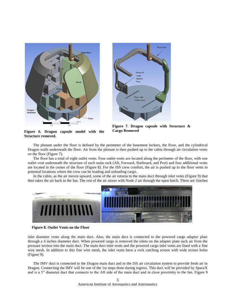
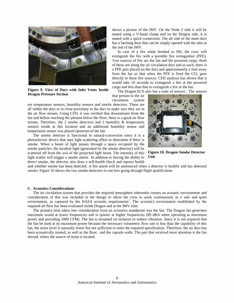
The fan is mounted to the Dragon forward wall structure above the floor rack and has a shroud that surrounds its
outlet and an inlet. The duct leading to the floor opens up into a larger area where a suite of sensors reside. Figure 6
shows Dragon capsule model with structure removed to show the cargo racks, floor, and duct. Figure 7 shows
Dragon capsule model with the racks removed to show the duct and the floor with outlet vents more clearly.
Figure 4. Intra-Vehicle Circulation Requirement
Dragon Spacecraft
Internal Volume
> 6 inches from
Cabin Isle way
Surfaces
Flow: 10 – 40 ft/min
7 < Flow < 10 ft/min
Flow > 40 ft/min
Flow < 7 ft/min
67 % of
Volume
5 % of
Volume
~ 28 % of
Volume
Figure 5. Air Circulation Fan
Page 5
American Institute of Aeronautics and Astronautics
5
The plenum under the floor is defined by the perimeter of the basement lockers, the floor, and the cylindrical
Dragon walls underneath the floor. Air from the plenum is then pushed up to the cabin through air circulation vents
on the floor (Figure 7).
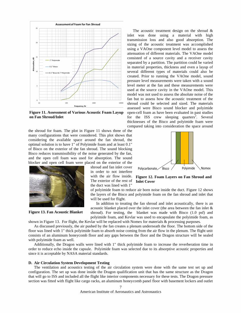
The floor has a total of eight outlet vents. Four outlet vents are located along the perimeter of the floor, with one
outlet vent underneath the structure of each main rack (Aft, Forward, Starboard, and Port) and four additional vents
are located in the center of the floor (Figure 8). For the ISS crew comfort, the air is pushed up to the floor vents in
potential locations where the crew can be loading and unloading cargo.
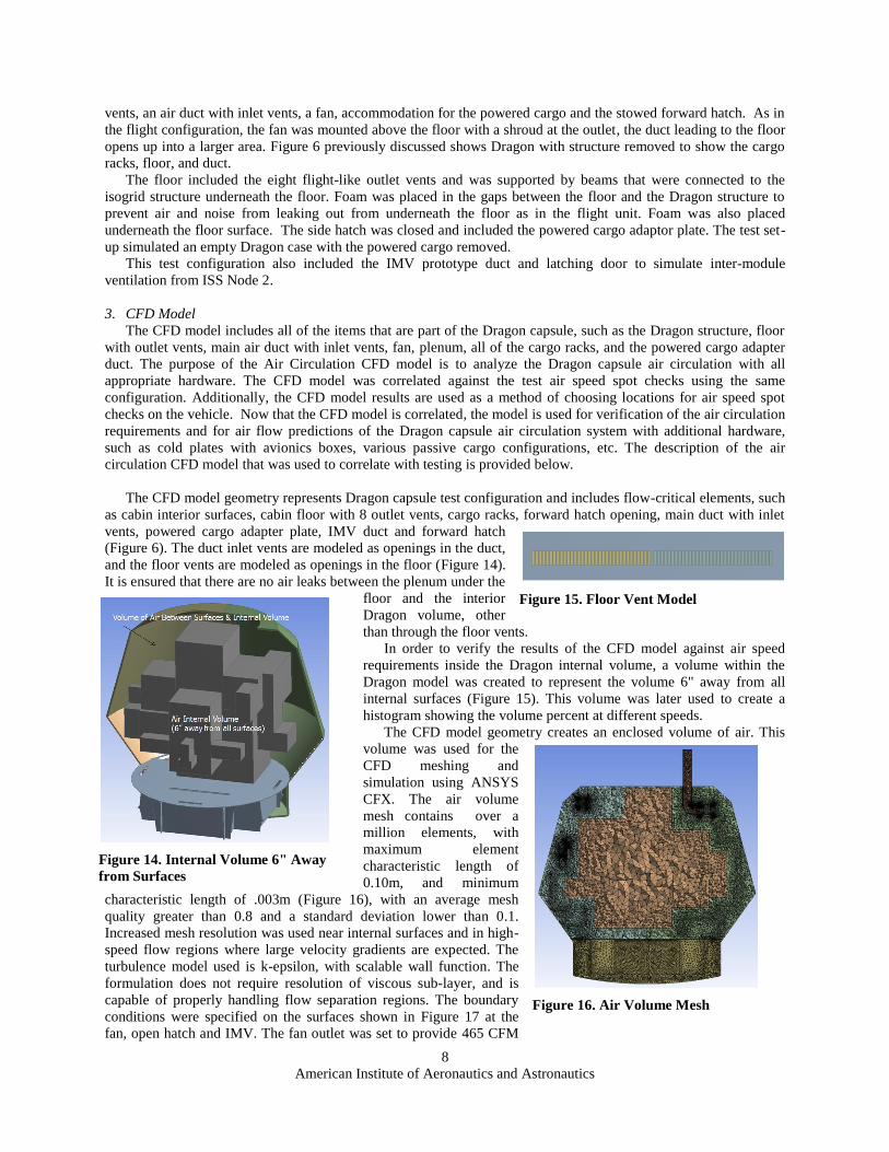
In the cabin, as the air moves upward, some of the air returns to the main duct through inlet vents (Figure 9) that
then takes the air back to the fan. The rest of the air mixes with Node 2 air through the open hatch. There are 3inches
inlet diameter vents along the main duct. Also, the main duct is connected to the powered cargo adapter plate
through a 4 inches diameter duct. When powered cargo is removed the inlets on the adapter plate suck air from the
pressure section into the main duct. The main duct inlet vents and the powered cargo inlet vents are lined with a fine
wire mesh. In addition to this fine wire mesh, the inlet vents have a rock catching screen with wide screen holes
(Figure 9).
The IMV duct is connected to the Dragon main duct and to the ISS air circulation system to provide fresh air in
Dragon. Connecting the IMV will be one of the 1st steps done during ingress. This duct will be provided by SpaceX
and is a 5” diameter duct that connects to the Aft side of the main duct and in close proximity to the fan. Figure 9
Figure 6. Dragon capsule model with the
Structure removed.
Figure 7. Dragon capsule with Structure &
Cargo Removed
Figure 8. Outlet Vents on the Floor
Page 6
American Institute of Aeronautics and Astronautics
6
shows a picture of the IMV. On the Node 2 side it will be
mated using a V-band clamp and on the Dragon side, it is
mated with a quick connection. The aft side of the main duct
has a latching door that can be simply opened with the tabs at
the end of the IMV.
In case of a fire while berthed to ISS, the crew will
extinguish the fire with a portable fire extinguisher (PFE).
Two sources of fire are the fan and the powered cargo. Both
of these are along the air circulation duct and as such, there is
a PFE port placed on the duct and approximately a foot away
from the fan so that when the PFE is fired the CO2 goes
directly to these fire sources. CFD analysis has shown that it
would take 10 seconds to extinguish a fire at the powered
cargo and less than that to extinguish a fire at the fan.
The Dragon ECS also has a suite of sensors . The sensors
that pertain to the air
circulation system
are temperature sensors, humidity sensors and smoke detectors. These are
all within the duct or in close proximity to the duct to make sure they are in
the air flow stream. Using CFD, it was verified that downstream from the
fan and before reaching the plenum below the floor, there is a good air flow
stream. Therefore, the 2 smoke detectors and 2 humidity & temperature
sensors reside at this location and an additional humidity sensor and
temperature sensor was placed upstream of the fan.
The smoke detector is functional in natural-convection since it is a
photoelectric device that uses light scattering effect to determine if there is
smoke. When a beam of light passes through a space occupied by the
smoke particles, the incident light (generated by the smoke detector) will be
scattered off from the axis of the projected light beam. The intensity of this
light scatter will trigger a smoke alarm. In addition to having the ability to
detect smoke, the detector also does a self-health check and reports health
and whether smoke has been detected. A fire alarm will be announced when a detector is healthy and has detected
smoke. Figure 10 shows the two smoke detectors in one box going through flight qualification.
C. Acoustics Considerations
The air circulation system that provides the required atmosphere inherently creates an acoustic environment and
consideration of this was included in the design to allow the crew to work continuously in a safe and quiet
environment, as captured by the NASA acoustic requirements1. The acoustics environment established by the
required air flow has been evaluated inside Dragon and at the IMV inlet.
The primary item taken into consideration from an acoustics standpoint was the fan. The Dragon fan generates
maximum sound at lower frequencies and is quieter at higher frequencies (69 dBA when operating at maximum
power and providing 1800 CFM). The fan is mounted on isolators to reduce vibration. Since it is not required that
the fan be used at its maximum power because the necessary volumetric flow rate is less than the capability of this
fan, the noise level is naturally lower but not sufficient to meet the required specification. Therefore, the air duct has
been acoustically treated, as well as the floor, and the capsule walls. The part that received more attention is the fan
shroud, where the source of noise is located.
Figure 9. View of Duct with Inlet Vents Inside
Dragon Pressure Section
Figure 10. Dragon Smoke Detector
Unit
Page 7
American Institute of Aeronautics and Astronautics
7
The acoustic treatment design on the shroud &
inlet was done using a material with high
transmission loss and also good absorption. The
sizing of the acoustic treatment was accomplished
using a VAOne component level model to assess the
attenuation of different materials. The VAOne model
consisted of a source cavity and a receiver cavity
separated by a partition. The partition could be varied
in material properties, thickness and even a layup of
several different types of materials could also be
created. Prior to running the VAOne model, sound
pressure level measurements were taken with a sound
level meter at the fan and these measurements were
used at the source cavity in the VAOne model. This
model was not used to assess the absolute noise of the
fan but to assess how the acoustic treatment of the
shroud could be selected and sized. The materials
assessed were Bisco sound blocker and polyimide
open-cell foam as have been evaluated in past studies
for the ISS crew sleeping quarters2. Several
thicknesses of the Bisco and polyimide foam were
compared taking into consideration the space around
the shroud for foam. The plot in Figure 11 shows three of the
many configurations that were considered. This plot shows that
considering the available space around the fan shroud, the
optimal solution is to have 1" of Polyimide foam and at least 0.1"
of Bisco on the exterior of the fan shroud. The sound blocking
Bisco reduces transmissibility of the noise generated by the fan,
and the open cell foam was used for absorption. The sound
blocker and open cell foam were placed on the exterior of the
shroud and fan inlet cover
in order to not interfere
with the air flow inside.
The exterior of the rest of
the duct was lined with 1"
of polyimide foam to reduce air born noise inside the duct. Figure 12 shows
the layers of the Bisco and polyimide foam on the fan shroud and inlet that
will be used for flight.
In addition to treating the fan shroud and inlet acoustically, there is an
acoustic blanket placed over the inlet cover (the area between the fan inlet &
shroud). For testing, the blanket was made with Bisco (1.0 psf) and
polyimide foam, and Kevlar was used to encapsulate the polyimide foam, as
shown in Figure 13. For flight, the Kevlar will be replaced with Nomex for materials & processing purposes.
As discussed previously, the air pushed by the fan creates a plenum underneath the floor. The bottom side of the
floor was lined with 1" thick polyimide foam to absorb noise coming from the air flow in the plenum. The flight unit
consists of an aluminum honeycomb floor and any gaps between the floor and the Dragon structure will be sealed
with polyimide foam as well.
Additionally, the Dragon walls were lined with 1" thick polyimide foam to increase the reverberation time in
order to reduce echo inside the capsule. Polyimide foam was selected due to its absorptive acoustic properties and
since it is acceptable by NASA material standards.
D. Air Circulation System Development Testing
The ventilation and acoustics testing of the air circulation system were done with the same test set up and
configuration. The set up was done inside the Dragon qualification unit that has the same structure as the Dragon
that will go to ISS and included all the flight like interior components necessary for these tests. The Dragon pressure
section was fitted with flight like cargo racks, an aluminum honeycomb panel floor with basement lockers and outlet
Figure 11. Assessment of Various Acoustic Foam Layup
on Fan Shroud/Inlet
0
5
10
15
20
25
10 100 1000 10000
Att
en
ua
tio
n, d
B
Frequency, Hz
Assessment of Foam for Fan Shroud
1" Polyimide
0.1" Bisco
0.1" Bisco & 1" Polyimide
Figure 12. Foam Layers on Fan Shroud and
Inlet Cover
Nomex Polycarbonate Bisco Polyimide
Figure 13. Fan Acoustic Blanket
Page 8
American Institute of Aeronautics and Astronautics
8
vents, an air duct with inlet vents, a fan, accommodation for the powered cargo and the stowed forward hatch. As in
the flight configuration, the fan was mounted above the floor with a shroud at the outlet, the duct leading to the floor
opens up into a larger area. Figure 6 previously discussed shows Dragon with structure removed to show the cargo
racks, floor, and duct.
The floor included the eight flight-like outlet vents and was supported by beams that were connected to the
isogrid structure underneath the floor. Foam was placed in the gaps between the floor and the Dragon structure to
prevent air and noise from leaking out from underneath the floor as in the flight unit. Foam was also placed
underneath the floor surface. The side hatch was closed and included the powered cargo adaptor plate. The test set-
up simulated an empty Dragon case with the powered cargo removed.
This test configuration also included the IMV prototype duct and latching door to simulate inter-module
ventilation from ISS Node 2.
3. CFD Model
The CFD model includes all of the items that are part of the Dragon capsule, such as the Dragon structure, floor
with outlet vents, main air duct with inlet vents, fan, plenum, all of the cargo racks, and the powered cargo adapter
duct. The purpose of the Air Circulation CFD model is to analyze the Dragon capsule air circulation with all
appropriate hardware. The CFD model was correlated against the test air speed spot checks using the same
configuration. Additionally, the CFD model results are used as a method of choosing locations for air speed spot
checks on the vehicle. Now that the CFD model is correlated, the model is used for verification of the air circulation
requirements and for air flow predictions of the Dragon capsule air circulation system with additional hardware,
such as cold plates with avionics boxes, various passive cargo configurations, etc. The description of the air
circulation CFD model that was used to correlate with testing is provided below.
The CFD model geometry represents Dragon capsule test configuration and includes flow-critical elements, such
as cabin interior surfaces, cabin floor with 8 outlet vents, cargo racks, forward hatch opening, main duct with inlet
vents, powered cargo adapter plate, IMV duct and forward hatch
(Figure 6). The duct inlet vents are modeled as openings in the duct,
and the floor vents are modeled as openings in the floor (Figure 14).
It is ensured that there are no air leaks between the plenum under the
floor and the interior
Dragon volume, other
than through the floor vents.
In order to verify the results of the CFD model against air speed
requirements inside the Dragon internal volume, a volume within the
Dragon model was created to represent the volume 6" away from all
internal surfaces (Figure 15). This volume was later used to create a
histogram showing the volume percent at different speeds.
The CFD model geometry creates an enclosed volume of air. This
volume was used for the
CFD meshing and
simulation using ANSYS
CFX. The air volume
mesh contains over a
million elements, with
maximum element
characteristic length of
0.10m, and minimum
characteristic length of .003m (Figure 16), with an average mesh
quality greater than 0.8 and a standard deviation lower than 0.1.
Increased mesh resolution was used near internal surfaces and in high-
speed flow regions where large velocity gradients are expected. The
turbulence model used is k-epsilon, with scalable wall function. The
formulation does not require resolution of viscous sub-layer, and is
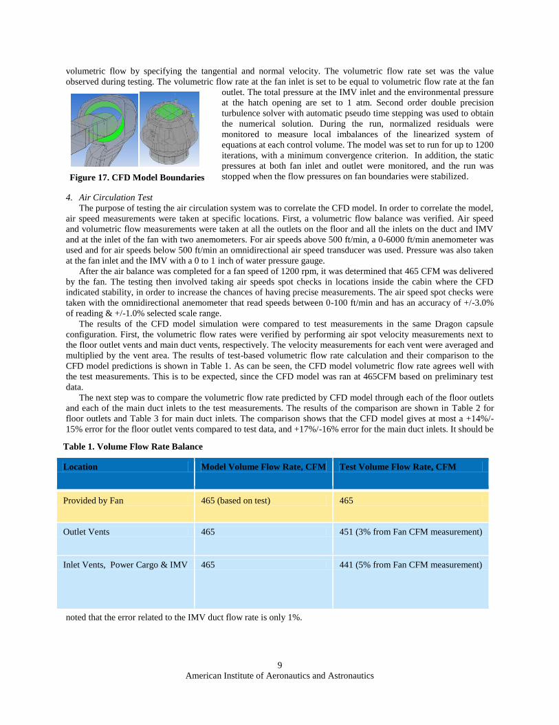
capable of properly handling flow separation regions. The boundary
conditions were specified on the surfaces shown in Figure 17 at the
fan, open hatch and IMV. The fan outlet was set to provide 465 CFM
Figure 15. Floor Vent Model
Figure 14. Internal Volume 6" Away
from Surfaces
Figure 16. Air Volume Mesh
Page 9
American Institute of Aeronautics and Astronautics
9
volumetric flow by specifying the tangential and normal velocity. The volumetric flow rate set was the value
observed during testing. The volumetric flow rate at the fan inlet is set to be equal to volumetric flow rate at the fan
outlet. The total pressure at the IMV inlet and the environmental pressure
at the hatch opening are set to 1 atm. Second order double precision
turbulence solver with automatic pseudo time stepping was used to obtain
the numerical solution. During the run, normalized residuals were
monitored to measure local imbalances of the linearized system of
equations at each control volume. The model was set to run for up to 1200
iterations, with a minimum convergence criterion. In addition, the static
pressures at both fan inlet and outlet were monitored, and the run was
stopped when the flow pressures on fan boundaries were stabilized.
4. Air Circulation Test
The purpose of testing the air circulation system was to correlate the CFD model. In order to correlate the model,
air speed measurements were taken at specific locations. First, a volumetric flow balance was verified. Air speed
and volumetric flow measurements were taken at all the outlets on the floor and all the inlets on the duct and IMV
and at the inlet of the fan with two anemometers. For air speeds above 500 ft/min, a 0-6000 ft/min anemometer was
used and for air speeds below 500 ft/min an omnidirectional air speed transducer was used. Pressure was also taken
at the fan inlet and the IMV with a 0 to 1 inch of water pressure gauge.
After the air balance was completed for a fan speed of 1200 rpm, it was determined that 465 CFM was delivered
by the fan. The testing then involved taking air speeds spot checks in locations inside the cabin where the CFD
indicated stability, in order to increase the chances of having precise measurements. The air speed spot checks were
taken with the omnidirectional anemometer that read speeds between 0-100 ft/min and has an accuracy of +/-3.0%
of reading & +/-1.0% selected scale range.
The results of the CFD model simulation were compared to test measurements in the same Dragon capsule
configuration. First, the volumetric flow rates were verified by performing air spot velocity measurements next to
the floor outlet vents and main duct vents, respectively. The velocity measurements for each vent were averaged and
multiplied by the vent area. The results of test-based volumetric flow rate calculation and their comparison to the
CFD model predictions is shown in Table 1. As can be seen, the CFD model volumetric flow rate agrees well with
the test measurements. This is to be expected, since the CFD model was ran at 465CFM based on preliminary test
data.
The next step was to compare the volumetric flow rate predicted by CFD model through each of the floor outlets
and each of the main duct inlets to the test measurements. The results of the comparison are shown in Table 2 for
floor outlets and Table 3 for main duct inlets. The comparison shows that the CFD model gives at most a +14%/-
15% error for the floor outlet vents compared to test data, and +17%/-16% error for the main duct inlets. It should be
noted that the error related to the IMV duct flow rate is only 1%.
Figure 17. CFD Model Boundaries
Table 1. Volume Flow Rate Balance
Location Model Volume Flow Rate, CFM Test Volume Flow Rate, CFM
Provided by Fan 465 (based on test) 465
Outlet Vents 465 451 (3% from Fan CFM measurement)
Inlet Vents, Power Cargo & IMV 465 441 (5% from Fan CFM measurement)
Page 10
American Institute of Aeronautics and Astronautics
10
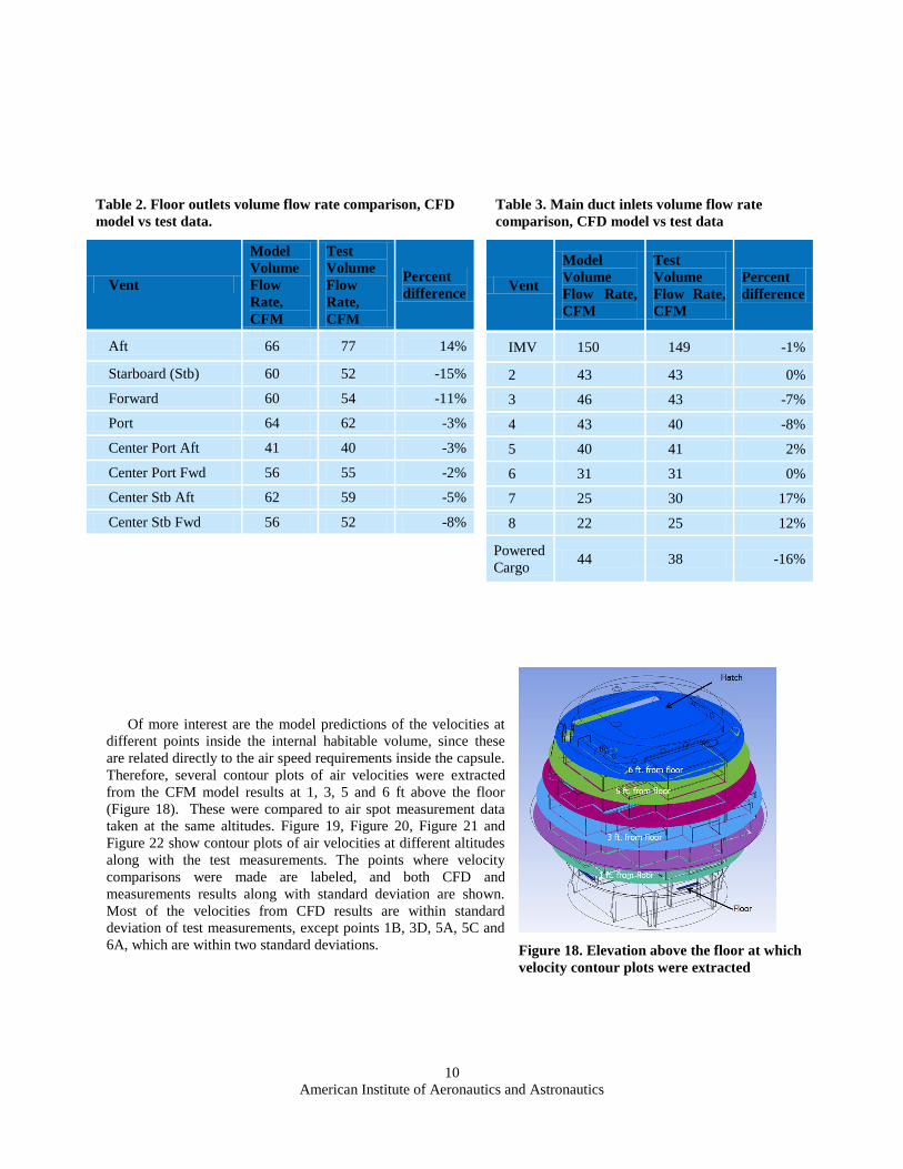
Of more interest are the model predictions of the velocities at
different points inside the internal habitable volume, since these
are related directly to the air speed requirements inside the capsule.
Therefore, several contour plots of air velocities were extracted
from the CFM model results at 1, 3, 5 and 6 ft above the floor
(Figure 18). These were compared to air spot measurement data
taken at the same altitudes. Figure 19, Figure 20, Figure 21 and
Figure 22 show contour plots of air velocities at different altitudes
along with the test measurements. The points where velocity
comparisons were made are labeled, and both CFD and
measurements results along with standard deviation are shown.
Most of the velocities from CFD results are within standard
deviation of test measurements, except points 1B, 3D, 5A, 5C and
6A, which are within two standard deviations.
Table 2. Floor outlets volume flow rate comparison, CFD
model vs test data.
Vent
Model
Volume
Flow
Rate,
CFM
Test
Volume
Flow
Rate,
CFM
Percent
difference
Aft 66 77 14%
Starboard (Stb) 60 52 -15%
Forward 60 54 -11%
Port 64 62 -3%
Center Port Aft 41 40 -3%
Center Port Fwd 56 55 -2%
Center Stb Aft 62 59 -5%
Center Stb Fwd 56 52 -8%
Table 3. Main duct inlets volume flow rate
comparison, CFD model vs test data
Vent
Model
Volume
Flow Rate,
CFM
Test
Volume
Flow Rate,
CFM
Percent
difference
IMV 150 149 -1%
2 43 43 0%
3 46 43 -7%
4 43 40 -8%
5 40 41 2%
6 31 31 0%
7 25 30 17%
8 22 25 12%
Powered
Cargo 44 38 -16%
Figure 18. Elevation above the floor at which
velocity contour plots were extracted
Page 11
American Institute of Aeronautics and Astronautics
11
E. Equations, Numbers, Symbols, and Abbreviations
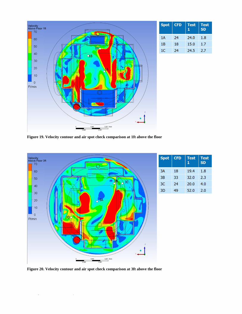
Figure 19. Velocity contour and air spot check comparison at 1ft above the floor
Figure 20. Velocity contour and air spot check comparison at 3ft above the floor
Page 12
American Institute of Aeronautics and Astronautics
12
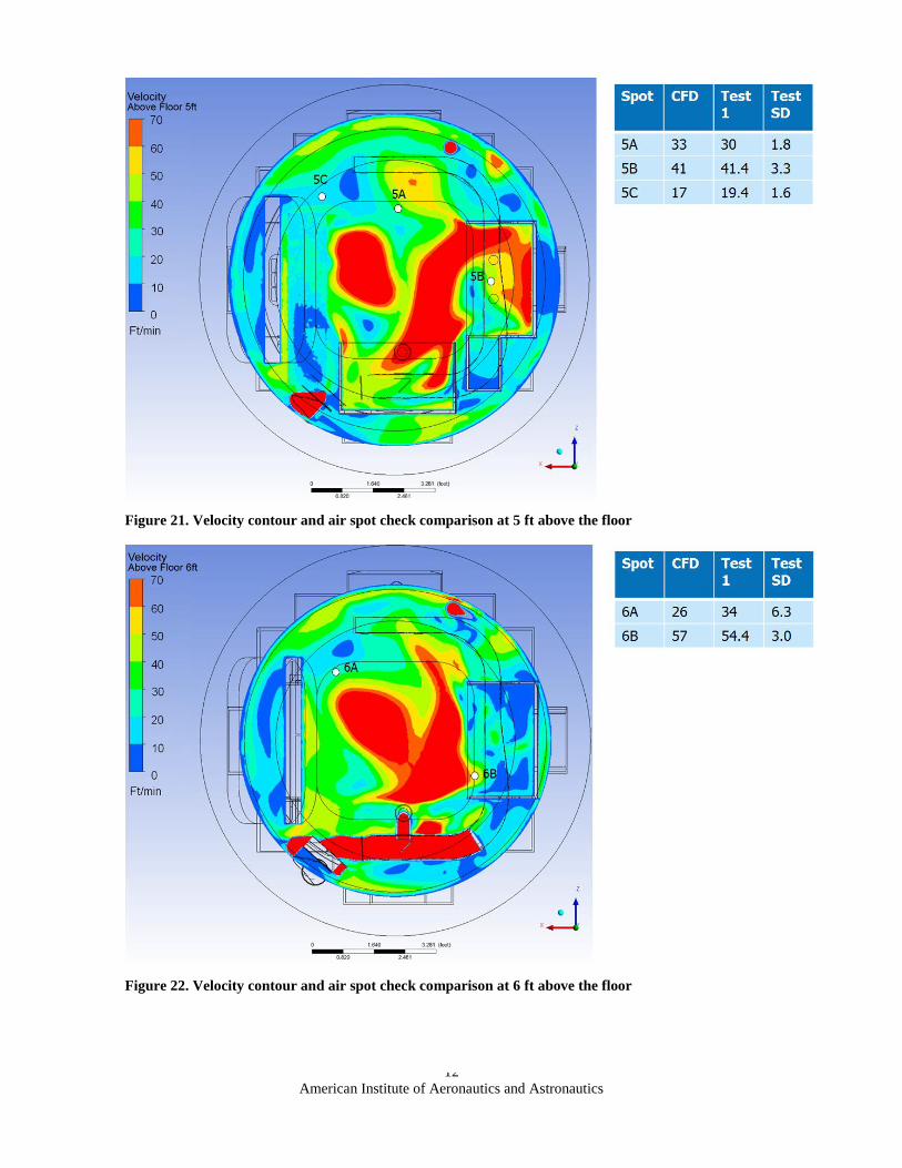
Figure 21. Velocity contour and air spot check comparison at 5 ft above the floor
Figure 22. Velocity contour and air spot check comparison at 6 ft above the floor
Page 13
American Institute of Aeronautics and Astronautics
13
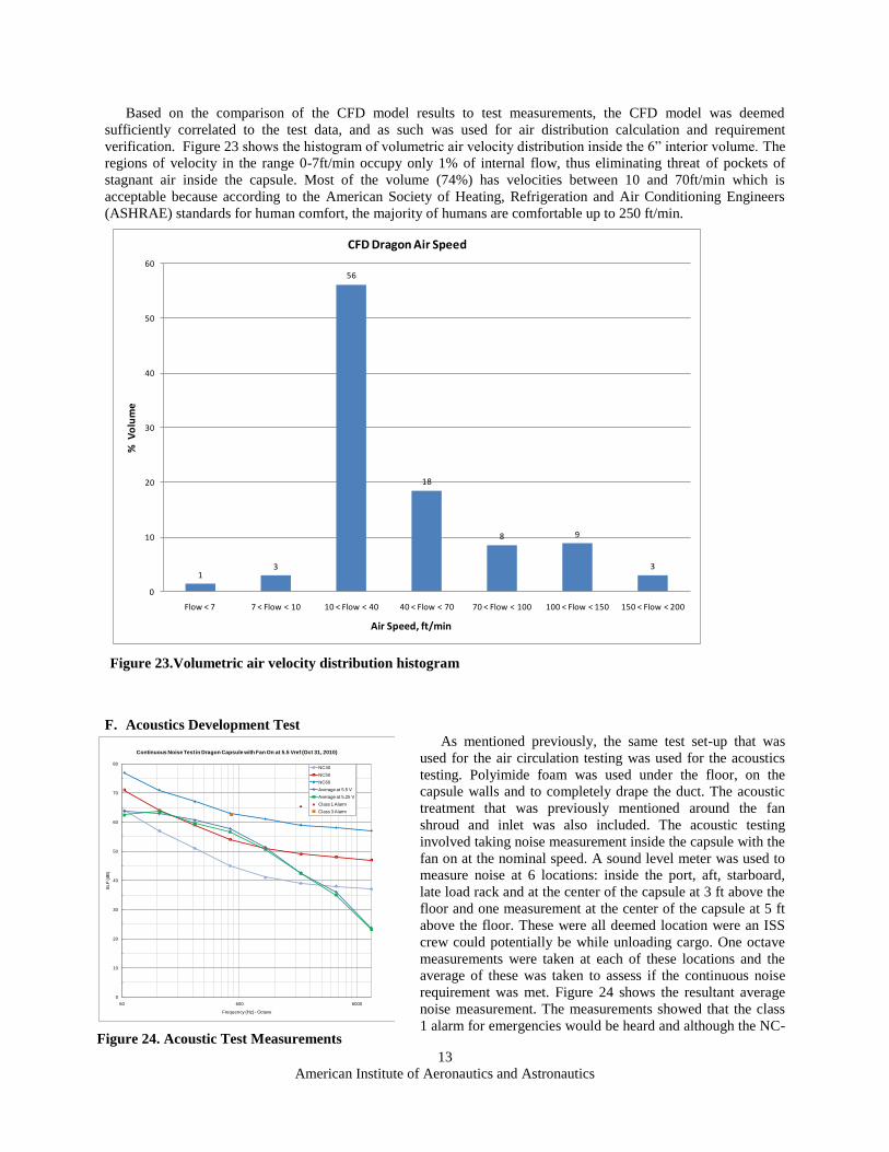
Based on the comparison of the CFD model results to test measurements, the CFD model was deemed
sufficiently correlated to the test data, and as such was used for air distribution calculation and requirement
verification. Figure 23 shows the histogram of volumetric air velocity distribution inside the 6” interior volume. The
regions of velocity in the range 0-7ft/min occupy only 1% of internal flow, thus eliminating threat of pockets of
stagnant air inside the capsule. Most of the volume (74%) has velocities between 10 and 70ft/min which is
acceptable because according to the American Society of Heating, Refrigeration and Air Conditioning Engineers
(ASHRAE) standards for human comfort, the majority of humans are comfortable up to 250 ft/min.
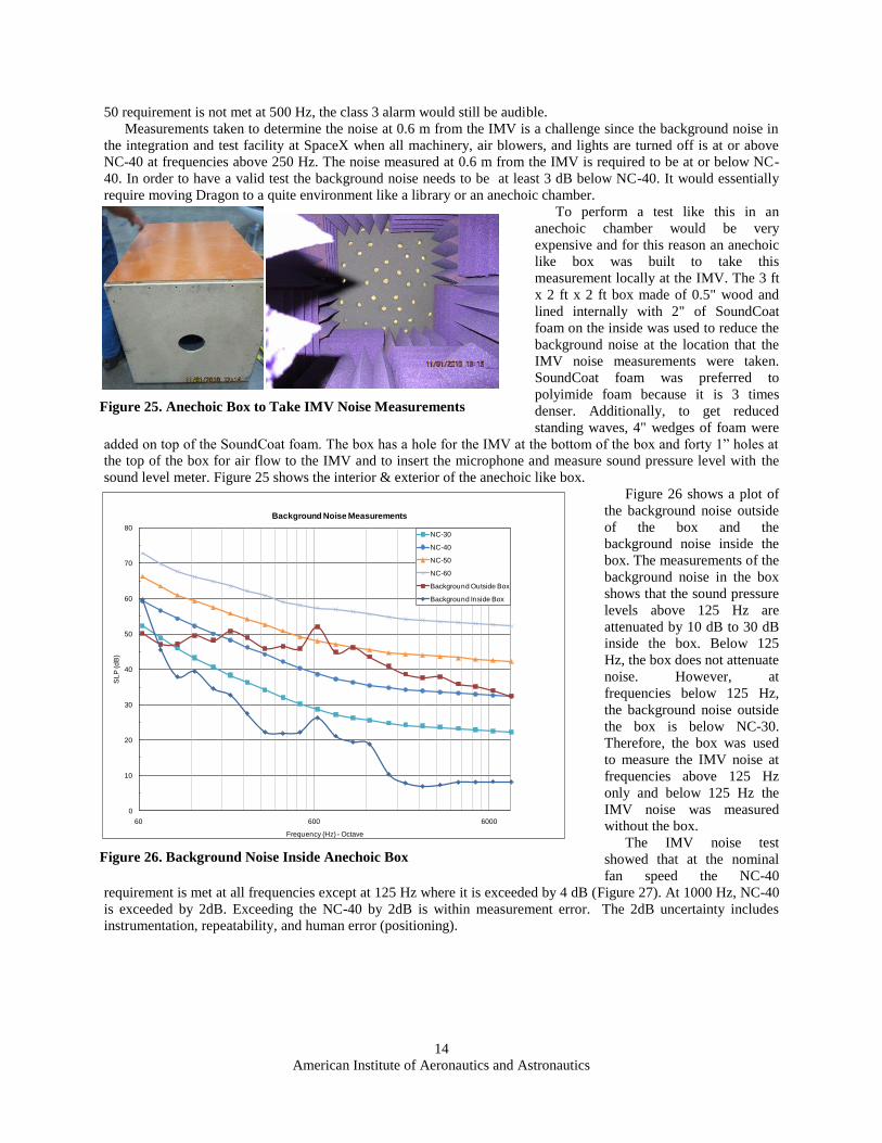
F. Acoustics Development Test
As mentioned previously, the same test set-up that was
used for the air circulation testing was used for the acoustics
testing. Polyimide foam was used under the floor, on the
capsule walls and to completely drape the duct. The acoustic
treatment that was previously mentioned around the fan
shroud and inlet was also included. The acoustic testing
involved taking noise measurement inside the capsule with the
fan on at the nominal speed. A sound level meter was used to
measure noise at 6 locations: inside the port, aft, starboard,
late load rack and at the center of the capsule at 3 ft above the
floor and one measurement at the center of the capsule at 5 ft
above the floor. These were all deemed location were an ISS
crew could potentially be while unloading cargo. One octave
measurements were taken at each of these locations and the
average of these was taken to assess if the continuous noise
requirement was met. Figure 24 shows the resultant average
noise measurement. The measurements showed that the class
1 alarm for emergencies would be heard and although the NC-
Figure 23.Volumetric air velocity distribution histogram
13
56
18
8 9
3
0
10
20
30
40
50
60
Flow < 7 7 < Flow < 10 10 < Flow < 40 40 < Flow < 70 70 < Flow < 100 100 < Flow < 150 150 < Flow < 200
% V
olu
me
Air Speed, ft/min
CFD Dragon Air Speed
Figure 24. Acoustic Test Measurements
0
10
20
30
40
50
60
70
80
60 600 6000
SL
P (d
B)
Frequency (Hz) - Octave
Continuous Noise Test in Dragon Capsule with Fan On at 5.5 Vref (Oct 31, 2010)
NC40
NC50
NC60
Average at 5.5 V
Average at 5.25 V
Class 1 Alarm
Class 3 Alarm
Page 14
American Institute of Aeronautics and Astronautics
14
50 requirement is not met at 500 Hz, the class 3 alarm would still be audible.
Measurements taken to determine the noise at 0.6 m from the IMV is a challenge since the background noise in
the integration and test facility at SpaceX when all machinery, air blowers, and lights are turned off is at or above
NC-40 at frequencies above 250 Hz. The noise measured at 0.6 m from the IMV is required to be at or below NC-
40. In order to have a valid test the background noise needs to be at least 3 dB below NC-40. It would essentially
require moving Dragon to a quite environment like a library or an anechoic chamber.
To perform a test like this in an
anechoic chamber would be very
expensive and for this reason an anechoic
like box was built to take this
measurement locally at the IMV. The 3 ft
x 2 ft x 2 ft box made of 0.5" wood and
lined internally with 2" of SoundCoat
foam on the inside was used to reduce the
background noise at the location that the
IMV noise measurements were taken.
SoundCoat foam was preferred to
polyimide foam because it is 3 times
denser. Additionally, to get reduced
standing waves, 4" wedges of foam were
added on top of the SoundCoat foam. The box has a hole for the IMV at the bottom of the box and forty 1” holes at
the top of the box for air flow to the IMV and to insert the microphone and measure sound pressure level with the
sound level meter. Figure 25 shows the interior & exterior of the anechoic like box.
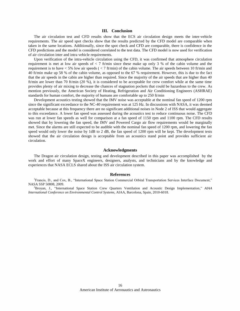
Figure 26 shows a plot of
the background noise outside
of the box and the
background noise inside the
box. The measurements of the
background noise in the box
shows that the sound pressure
levels above 125 Hz are
attenuated by 10 dB to 30 dB
inside the box. Below 125
Hz, the box does not attenuate
noise. However, at
frequencies below 125 Hz,
the background noise outside
the box is below NC-30.
Therefore, the box was used
to measure the IMV noise at
frequencies above 125 Hz
only and below 125 Hz the
IMV noise was measured
without the box.
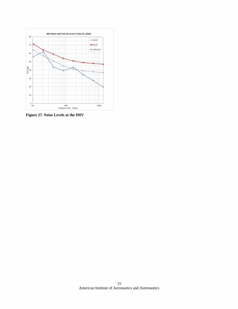
The IMV noise test
showed that at the nominal
fan speed the NC-40
requirement is met at all frequencies except at 125 Hz where it is exceeded by 4 dB (Figure 27). At 1000 Hz, NC-40
is exceeded by 2dB. Exceeding the NC-40 by 2dB is within measurement error. The 2dB uncertainty includes
instrumentation, repeatability, and human error (positioning).
Figure 25. Anechoic Box to Take IMV Noise Measurements
Figure 26. Background Noise Inside Anechoic Box
0
10
20
30
40
50
60
70
80
60 600 6000
SL
P (d
B)
Frequency (Hz) - Octave
Background Noise Measurements
NC-30
NC-40
NC-50
NC-60
Background Outside Box
Background Inside Box
Page 15
American Institute of Aeronautics and Astronautics
15
Figure 27. Noise Levels at the IMV
0
10
20
30
40
50
60
70
80
60 600 6000
SL
P (
dB
)
Frequency (Hz) - Octave
IMV Noise with Fan On at 5.5 V (Oct 31, 2010)
NC40
NC50
1200 rpm
Page 16
American Institute of Aeronautics and Astronautics
16
III. Conclusion
The air circulation test and CFD results show that the ECS air circulation design meets the inter-vehicle
requirements. The air speed spot checks show that the results predicted by the CFD model are comparable when
taken in the same locations. Additionally, since the spot check and CFD are comparable, there is confidence in the
CFD predictions and the model is considered correlated to the test data. The CFD model is now used for verification
of air circulation inter and intra vehicle requirements.
Upon verification of the intra-vehicle circulation using the CFD, it was confirmed that atmosphere circulation
requirement is met at low air speeds of < 7 ft/min since these make up only 3 % of the cabin volume and the
requirement is to have < 5% low air speeds ( < 7 ft/min) of the cabin volume. The air speeds between 10 ft/min and
40 ft/min make up 58 % of the cabin volume, as opposed to the 67 % requirement. However, this is due to the fact
that the air speeds in the cabin are higher than required. Since the majority of the air speeds that are higher than 40
ft/min are lower than 70 ft/min (20 %), it is considered to be acceptable for crew comfort while at the same time
provides plenty of air mixing to decrease the chances of stagnation pockets that could be hazardous to the crew. As
mention previously, the American Society of Heating, Refrigeration and Air Conditioning Engineers (ASHRAE)
standards for human comfort, the majority of humans are comfortable up to 250 ft/min
Development acoustics testing showed that the IMV noise was acceptable at the nominal fan speed of 1200 rpm
since the significant exceedance to the NC-40 requirement was at 125 Hz. In discussions with NASA, it was deemed
acceptable because at this frequency there are no significant additional noises in Node 2 of ISS that would aggregate
to this exceedance. A lower fan speed was assessed during the acoustics test to reduce continuous noise. The CFD
was run at lower fan speeds as well for comparison at a fan speed of 1150 rpm and 1100 rpm. The CFD results
showed that by lowering the fan speed, the IMV and Powered Cargo air flow requirements would be marginally
met. Since the alarms are still expected to be audible with the nominal fan speed of 1200 rpm, and lowering the fan
speed would only lower the noise by 1dB to 2 dB, the fan speed of 1200 rpm will be kept. The development tests
showed that the air circulation design is acceptable from an acoustics stand point and provides sufficient air
circulation.
Acknowledgments
The Dragon air circulation design, testing and development described in this paper was accomplished by the
work and effort of many SpaceX engineers, designers, analysts, and technicians and by the knowledge and
experiences that NASA ECLS shared about the ISS air circulation system.
References 1Francis, D., and Cox, B., “International Space Station Commercial Orbital Transportation Services Interface Document,”
NASA SSP 50808, 2009. 2Broyan, J., “International Space Station Crew Quarters Ventilation and Acoustic Design Implementation,” AIAA
International Conference on Environmental Control Systems, AIAA, Barcelona, Spain, 2010-6018.