68
SPARK PLUGS Discovering DENSO Technology
SPARK PLUGSDiscovering DENSO Technology
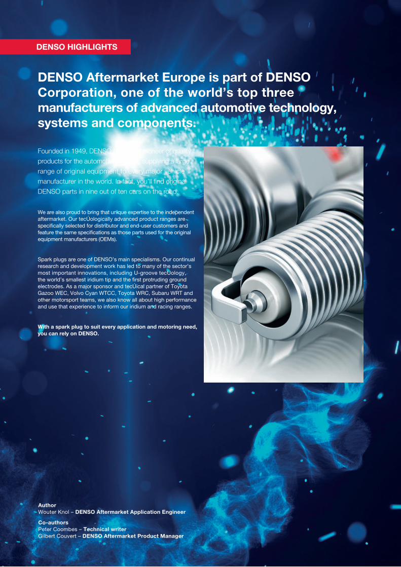
DENSO Aftermarket Europe is part of DENSO Corporation, one of the world’s top three manufacturers of advanced automotive technology, systems and components.
Founded in 1949, DENSO became a pioneer of quality
products for the automotive industry, supplying a large
range of original equipment to every major vehicle
manufacturer in the world. In fact, you’ll find original
DENSO parts in nine out of ten cars on the road.
We are also proud to bring that unique expertise to the independent aftermarket. Our technologically advanced product ranges are specifically selected for distributor and end-user customers and feature the same specifications as those parts used for the original equipment manufacturers (OEMs).
Spark plugs are one of DENSO’s main specialisms. Our continual research and development work has led to many of the sector’s most important innovations, including U-groove technology, the world’s smallest iridium tip and the first protruding ground electrodes. As a major sponsor and technical partner of Toyota Gazoo WEC, Volvo Cyan WTCC, Toyota WRC, Subaru WRT and other motorsport teams, we also know all about high performance and use that experience to inform our iridium and racing ranges.
With a spark plug to suit every application and motoring need, you can rely on DENSO.
Author Wouter Knol – DENSO Aftermarket Application Engineer
Co-authors Peter Coombes – Technical writer Gilbert Couvert – DENSO Aftermarket Product Manager
DENSO HIGHLIGHTS
Contents 1. INTRODUCTION TO SPARK PLUGS ........................................................................................................ 2 1.1. Spark plugs: a critical part of the combustion process ..................................................................................... 2 1.2. Operating requirements for modern spark plugs ............................................................................................... 3 1.3. Different spark plugs for different engines ......................................................................................................... 4
2. 4-STROKE ENGINE OPERATION AND COMBUSTION PROCESS ........................................................... 6 2.1. The 4-stroke cycle: intake, compression, ignition, exhaust ............................................................................... 6
3. COIL IGNITION SYSTEM OPERATION ...................................................................................................... 8 3.1. The tasks of an ignition system ........................................................................................................................... 8 3.2. The introduction of coil ignition ........................................................................................................................... 8 3.3. Ignition coils: transforming a low voltage into a high voltage ............................................................................ 9 3.4. Coil charge-up time and dwell period ................................................................................................................11 3.5. Ignition timing: providing the spark at the correct time .....................................................................................12
4. MECHANICAL AND ELECTRONIC IGNITION SYSTEMS .........................................................................16 4.1. Basic mechanical ignition system ......................................................................................................................16 4.2. Early type electronic ignition systems .............................................................................................................. 20 4.3. Modern electronic ignition systems .................................................................................................................. 21
5. THE COMBUSTION PROCESS IN DETAIL ..............................................................................................24 5.1. The combustion of fuel and oxygen .................................................................................................................. 24
5.2. Achieving good combustion.............................................................................................................................. 26 5.3. Causes and problems of poor combustion ...................................................................................................... 27
5.4. Pollutants and harmful emissions created during combustion ........................................................................ 29 5.5. Reducing emissions and improving fuel economy ........................................................................................... 30
6. SPARK PLUGS ....................................................................................................................................... 32 6.1. The key to combustion ...................................................................................................................................... 32 6.2. Performance requirements................................................................................................................................ 32 6.3. Spark plug structure .......................................................................................................................................... 33 6.4. Electric spark and required spark voltage ........................................................................................................ 35 6.5. Operating conditions affecting spark plug voltage .......................................................................................... 36 6.6. Heat-range ......................................................................................................................................................... 39 6.7. Flame quenching affecting flame generation and flame growth ......................................................................41
7. DENSO TECHNOLOGIES: IMPROVING SPARK PLUG PERFORMANCE ............................................... 42 7.1. DENSO development ......................................................................................................................................... 42 7.2. Electrode materials ............................................................................................................................................ 43 7.3. Centre materials ................................................................................................................................................ 44 7.4. Ground electrode ............................................................................................................................................... 45 7.5. Other technologies used on DENSO Spark Plugs ..............................................................................................47 7.6. Future trends...................................................................................................................................................... 48
8. DENSO RANGE ...................................................................................................................................... 50 8.1. Direct Fit............................................................................................................................................................. 50 8.2. Twin Tip .............................................................................................................................................................. 52 8.3. Iridium Power ..................................................................................................................................................... 53 8.4. Iridium Racing .................................................................................................................................................... 54
9. UPGRADE YOUR SPARK PLUGS........................................................................................................... 56 9.1. Why upgrade your spark plug? ......................................................................................................................... 56 9.2. Power output ..................................................................................................................................................... 57 9.3. Fuel economy and emissions ............................................................................................................................ 58 9.4. Smooth idling, misfires and starting ................................................................................................................. 59 9.5. LPG and CNG converted cars........................................................................................................................... 60 9.6. Tuning and racing .............................................................................................................................................. 61
10. FAQ, INSTALLATION AND TROUBLE SHOOTING .................................................................................. 62 10.1. FAQ .................................................................................................................................................................... 62 10.2. Correct installation of spark plugs .................................................................................................................... 64 10.3. Trouble shooting ................................................................................................................................................ 65
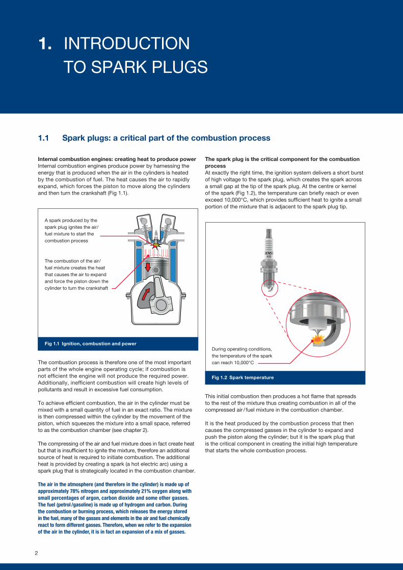
Fig 1.1 Ignition, combustion and power
Fig 1.2 Spark temperature
1.1 Spark plugs: a critical part of the combustion process
Internal combustion engines: creating heat to produce powerInternal combustion engines produce power by harnessing the energy that is produced when the air in the cylinders is heated by the combustion of fuel. The heat causes the air to rapidly expand, which forces the piston to move along the cylinders and then turn the crankshaft (Fig 1.1).
The combustion process is therefore one of the most important parts of the whole engine operating cycle; if combustion is not efficient the engine will not produce the required power. Additionally, inefficient combustion will create high levels of pollutants and result in excessive fuel consumption.
To achieve efficient combustion, the air in the cylinder must be mixed with a small quantity of fuel in an exact ratio. The mixture is then compressed within the cylinder by the movement of the piston, which squeezes the mixture into a small space, referred to as the combustion chamber (see chapter 2).
The compressing of the air and fuel mixture does in fact create heat but that is insufficient to ignite the mixture, therefore an additional source of heat is required to initiate combustion. The additional heat is provided by creating a spark (a hot electric arc) using a spark plug that is strategically located in the combustion chamber.
The air in the atmosphere (and therefore in the cylinder) is made up of approximately 78% nitrogen and approximately 21% oxygen along with small percentages of argon, carbon dioxide and some other gasses. The fuel (petrol /gasoline) is made up of hydrogen and carbon. During the combustion or burning process, which releases the energy stored in the fuel, many of the gasses and elements in the air and fuel chemically react to form different gasses. Therefore, when we refer to the expansion of the air in the cylinder, it is in fact an expansion of a mix of gasses.
The spark plug is the critical component for the combustion processAt exactly the right time, the ignition system delivers a short burst of high voltage to the spark plug, which creates the spark across a small gap at the tip of the spark plug. At the centre or kernel of the spark (Fig 1.2), the temperature can briefly reach or even exceed 10,000°C, which provides sufficient heat to ignite a small portion of the mixture that is adjacent to the spark plug tip.
This initial combustion then produces a hot flame that spreads to the rest of the mixture thus creating combustion in all of the compressed air / fuel mixture in the combustion chamber.
It is the heat produced by the combustion process that then causes the compressed gasses in the cylinder to expand and push the piston along the cylinder; but it is the spark plug that is the critical component in creating the initial high temperature that starts the whole combustion process.
A spark produced by the spark plug ignites the air /fuel mixture to start the combustion process
The combustion of the air /fuel mixture creates the heat that causes the air to expand and force the piston down the cylinder to turn the crankshaft
During operating conditions, the temperature of the spark can reach 10,000°C
2
1. INTRODUCTION TO SPARK PLUGS
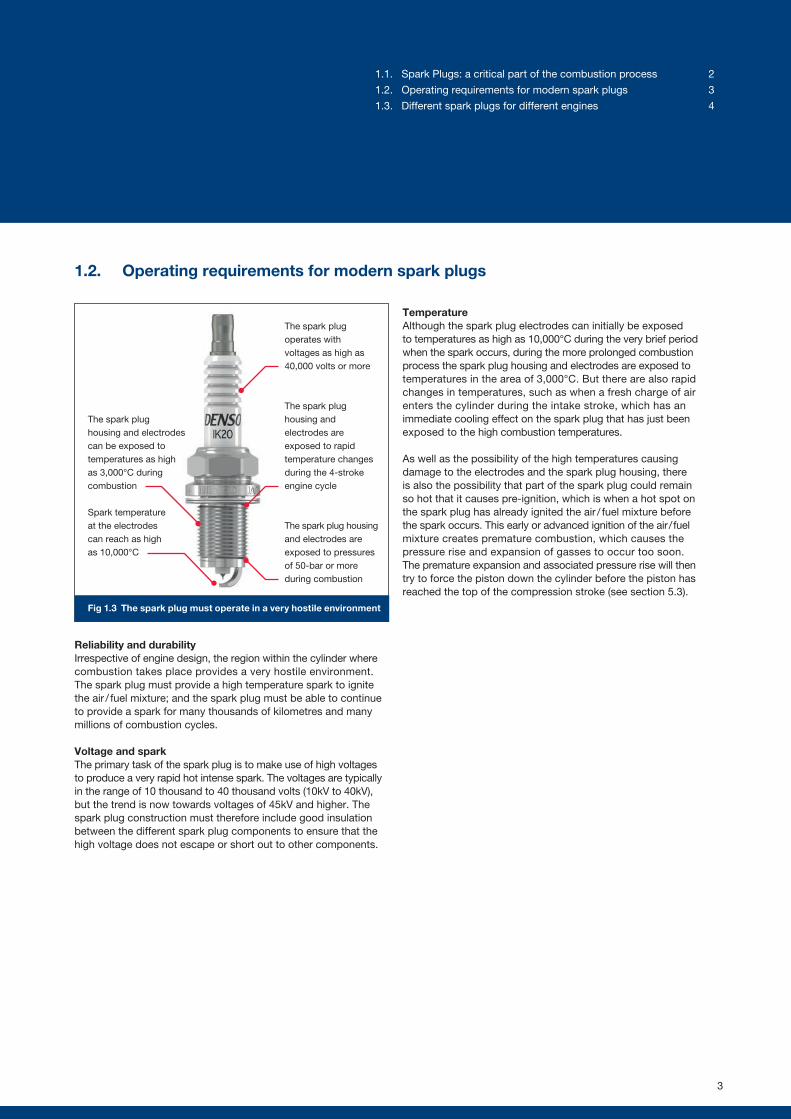
Fig 1.3 The spark plug must operate in a very hostile environment
1.2. Operating requirements for modern spark plugs
Reliability and durabilityIrrespective of engine design, the region within the cylinder where combustion takes place provides a very hostile environment. The spark plug must provide a high temperature spark to ignite the air / fuel mixture; and the spark plug must be able to continue to provide a spark for many thousands of kilometres and many millions of combustion cycles.
Voltage and sparkThe primary task of the spark plug is to make use of high voltages to produce a very rapid hot intense spark. The voltages are typically in the range of 10 thousand to 40 thousand volts (10kV to 40kV), but the trend is now towards voltages of 45kV and higher. The spark plug construction must therefore include good insulation between the different spark plug components to ensure that the high voltage does not escape or short out to other components.
TemperatureAlthough the spark plug electrodes can initially be exposed to temperatures as high as 10,000°C during the very brief period when the spark occurs, during the more prolonged combustion process the spark plug housing and electrodes are exposed to temperatures in the area of 3,000°C. But there are also rapid changes in temperatures, such as when a fresh charge of air enters the cylinder during the intake stroke, which has an immediate cooling effect on the spark plug that has just been exposed to the high combustion temperatures.
As well as the possibility of the high temperatures causing damage to the electrodes and the spark plug housing, there is also the possibility that part of the spark plug could remain so hot that it causes pre-ignition, which is when a hot spot on the spark plug has already ignited the air / fuel mixture before the spark occurs. This early or advanced ignition of the air / fuel mixture creates premature combustion, which causes the pressure rise and expansion of gasses to occur too soon. The premature expansion and associated pressure rise will then try to force the piston down the cylinder before the piston has reached the top of the compression stroke (see section 5.3).
The spark plug housing and electrodes can be exposed to temperatures as high as 3,000°C during combustion
The spark plug operates with voltages as high as 40,000 volts or more
Spark temperature at the electrodes can reach as high as 10,000°C
The spark plug housing and electrodes are exposed to rapid temperature changes during the 4-stroke engine cycle
The spark plug housing and electrodes are exposed to pressures of 50-bar or more during combustion
3
1.1. Spark Plugs: a critical part of the combustion process 2
1.2. Operating requirements for modern spark plugs 3
1.3. Different spark plugs for different engines 4
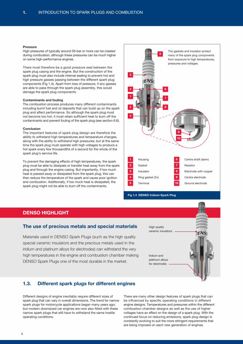
Fig 1.4 DENSO Iridium Spark Plug
PressureHigh pressures of typically around 50-bar or more can be created during combustion, although these pressures can be much higher on some high-performance engines.
There must therefore be a good pressure seal between the spark plug casing and the engine. But the construction of the spark plug must also include internal sealing to prevent hot and high pressure gasses passing between the different spark plug components (Fig 1.4). Apart from loss of pressure, if any gasses are able to pass through the spark plug assembly, this would damage the spark plug components.
Contaminants and fouling The combustion process produces many different contaminants including burnt fuel and oil deposits that can build up on the spark plug and affect performance. So although the spark plug must not become too hot, it must retain sufficient heat to burn off the contaminants and prevent fouling of the spark plug (see section 6.6).
ConclusionThe important features of spark plug design are therefore the ability to withstand high temperatures and temperature changes, along with the ability to withstand high pressures; but at the same time the spark plug must operate with high voltages to produce a hot spark every few thousandths of a second for the whole of the spark plug’s service life.
To prevent the damaging effects of high temperatures, the spark plug must be able to dissipate or transfer heat away from the spark plug and through the engine casing. But importantly, if too much heat is passed away or dissipated from the spark plug, this can then reduce the temperature of the spark and cause poor ignition and combustion. Additionally, if too much heat is dissipated, the spark plug might not be able to burn off the contaminants.
1.3. Different spark plugs for different engines
Different designs of engine inevitably require different sizes of spark plug that can vary in overall dimensions. The trend for narrow spark plugs for motorcycle applications began many years ago; but modern downsized car engines are now also fitted with these narrow spark plugs that still have to withstand the same hostile operating conditions.
There are many other design features of spark plugs that can be influenced by specific operating conditions in different engine designs. Temperatures and pressures within the different combustion chamber designs as well as the use of higher voltages have an effect on the design of a spark plug. With the continued focus on reducing emissions, spark plug design is constantly evolving to suit the more stringent requirements that are being imposed on each new generation of engines.
DENSO HIGHLIGHT
The use of precious metals and special materials
Materials used in DENSO Spark Plugs (such as the high quality
special ceramic insulators and the precious metals used in the
iridium and platinum alloys for electrodes) can withstand the very
high temperatures in the engine and combustion chamber making
DENSO Spark Plugs one of the most durable in the market.
The gaskets and insulator protect many of the spark plug components from exposure to high temperatures, pressures and voltages
Housing1 Centre shaft (stem)6
3
4
9
10
4
1
7
2
5
6
7
8
Gasket2 Resistor
Insulator3 Electrode with copper8
Ring gasket (2x)4 Centre electrode9
Terminal5 Ground electrode10
Iridium and platinum alloys for electrodes
High quality ceramic insulators
4
1. INTRODUCTION TO SPARK PLUGS AND COMBUSTION
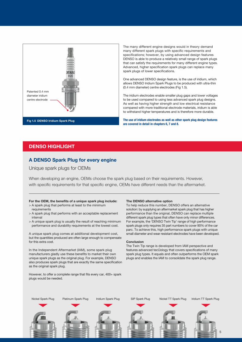
Fig 1.5 DENSO Iridium Spark Plug
DENSO HIGHLIGHT
The many different engine designs would in theory demand many different spark plugs with specific requirements and specifications; however, by using advanced design features DENSO is able to produce a relatively small range of spark plugs that can satisfy the requirements for many different engine types. Advanced, higher specification spark plugs can replace many spark plugs of lower specifications.
One advanced DENSO design feature, is the use of iridium, which allows DENSO Iridium Spark Plugs to be produced with ultra-thin (0.4 mm diameter) centre electrodes (Fig 1.5).
The iridium electrodes enable smaller plug gaps and lower voltages to be used compared to using less advanced spark plug designs. As well as having higher strength and low electrical resistance compared with more traditional electrode materials, iridium is able to withstand higher temperatures and is therefore more durable.
The use of iridium electrodes as well as other spark plug design features are covered in detail in chapters 6, 7 and 8.
For the OEM, the benefits of a unique spark plug include:> A spark plug that performs at least to the minimum
requirements> A spark plug that performs with an acceptable replacement
interval> A unique spark plug is usually the result of reaching minimum
performance and durability requirements at the lowest cost.
A unique spark plug comes at additional development cost, but the quantities produced are often large enough to compensate for this extra cost.
In the Independent Aftermarket (IAM), some spark plug manufacturers gladly use these benefits to market their own unique spark plugs as the original plug. For example, DENSO also produces spark plugs that are exactly the same specification as the original spark plug.
However, to offer a complete range that fits every car, 400+ spark plugs would be needed.
The DENSO alternative optionTo help reduce this number, DENSO offers an alternative solution: by supplying an aftermarket spark plug that has higher performance than the original, DENSO can replace multiple different spark plug types that often have only minor differences. For example, the ‘DENSO Twin Tip’ range of high performance spark plugs only requires 35 part numbers to cover 90% of the car parc. To achieve this, high performance spark plugs with unique small diameter and wear resistant electrodes have been developed.
ConclusionThe Twin Tip range is developed from IAM perspective and features advanced technology that covers specifications of many spark plug types. It equals and often outperforms the OEM spark plugs and enables the IAM to consolidate the spark plug range.
Nickel Spark Plug Platinum Spark Plug Iridium Spark Plug SIP Spark Plug Nickel TT Spark Plug Iridium TT Spark Plug
A DENSO Spark Plug for every engine
Unique spark plugs for OEMs
When developing an engine, OEMs choose the spark plug based on their requirements. However,
with specific requirements for that specific engine, OEMs have different needs than the aftermarket.
Patented 0.4 mm diameter iridium centre electrode
5
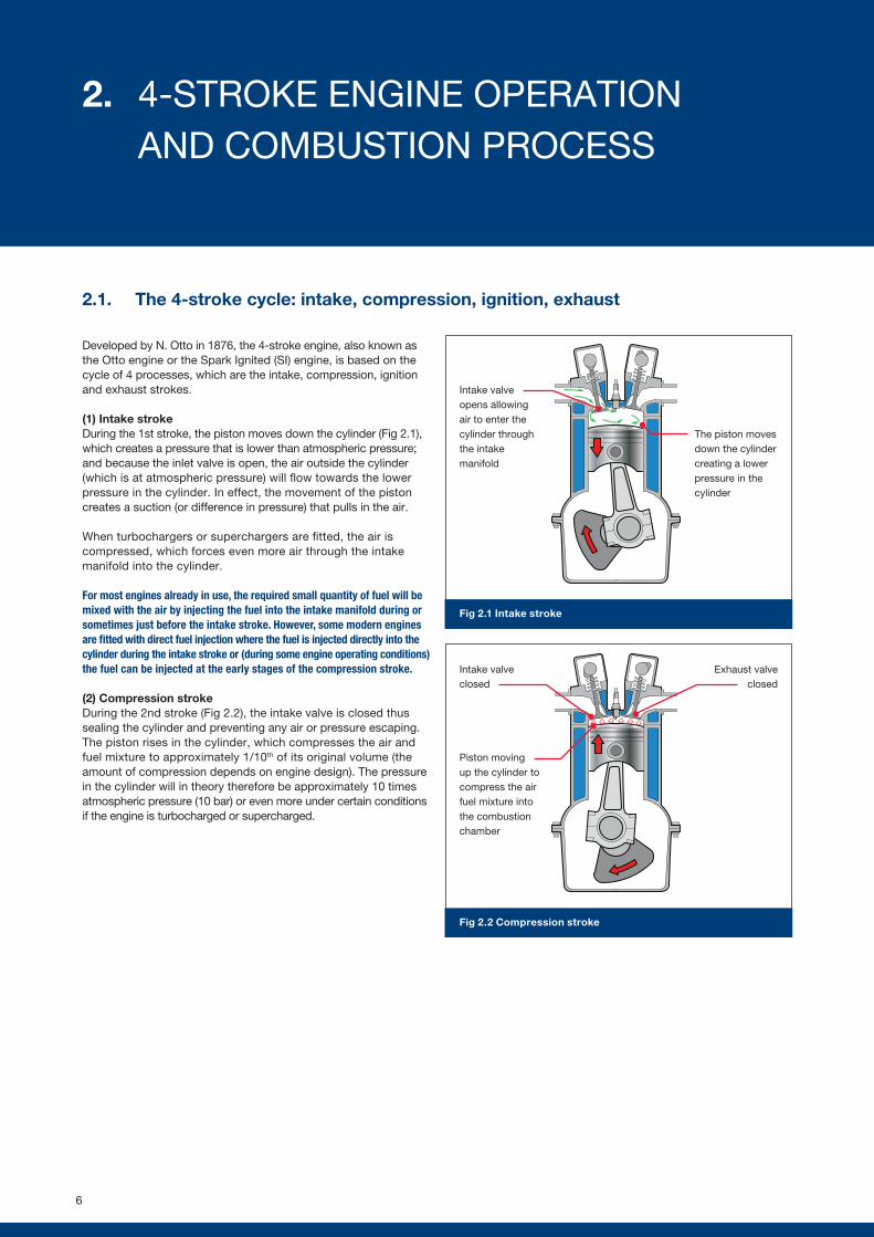
Fig 2.2 Compression stroke
Intake valve closed
Exhaust valve closed
Fig 2.1 Intake stroke
The piston moves down the cylinder creating a lower pressure in the cylinder
Intake valve opens allowing air to enter the cylinder through the intake manifold
2.1. The 4-stroke cycle: intake, compression, ignition, exhaust
Developed by N. Otto in 1876, the 4-stroke engine, also known as the Otto engine or the Spark Ignited (SI) engine, is based on the cycle of 4 processes, which are the intake, compression, ignition and exhaust strokes.
(1) Intake strokeDuring the 1st stroke, the piston moves down the cylinder (Fig 2.1), which creates a pressure that is lower than atmospheric pressure; and because the inlet valve is open, the air outside the cylinder (which is at atmospheric pressure) will flow towards the lower pressure in the cylinder. In effect, the movement of the piston creates a suction (or difference in pressure) that pulls in the air.
When turbochargers or superchargers are fitted, the air is compressed, which forces even more air through the intake manifold into the cylinder.
For most engines already in use, the required small quantity of fuel will be mixed with the air by injecting the fuel into the intake manifold during or sometimes just before the intake stroke. However, some modern engines are fitted with direct fuel injection where the fuel is injected directly into the cylinder during the intake stroke or (during some engine operating conditions) the fuel can be injected at the early stages of the compression stroke.
(2) Compression strokeDuring the 2nd stroke (Fig 2.2), the intake valve is closed thus sealing the cylinder and preventing any air or pressure escaping. The piston rises in the cylinder, which compresses the air and fuel mixture to approximately 1/10th of its original volume (the amount of compression depends on engine design). The pressure in the cylinder will in theory therefore be approximately 10 times atmospheric pressure (10 bar) or even more under certain conditions if the engine is turbocharged or supercharged.
Piston moving up the cylinder to compress the air fuel mixture into the combustion chamber
6
2. 4-STROKE ENGINE OPERATION AND COMBUSTION PROCESS
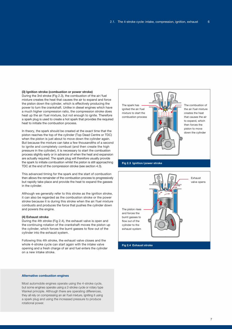
Fig 2.3 Ignition / power stroke
Fig 2.4 Exhaust stroke
(3) Ignition stroke (combustion or power stroke)During the 3rd stroke (Fig 2.3), the combustion of the air / fuel mixture creates the heat that causes the air to expand and force the piston down the cylinder, which is effectively producing the power to turn the crankshaft. Unlike in diesel engines which have a much higher compression ratio, the compression stroke does heat up the air / fuel mixture, but not enough to ignite. Therefore a spark plug is used to create a hot spark that provides the required heat to initiate the combustion process.
In theory, the spark should be created at the exact time that the piston reaches the top of the cylinder (Top Dead Centre or TDC) when the piston is just about to move down the cylinder again. But because the mixture can take a few thousandths of a second to ignite and completely combust (and then create the high pressure in the cylinder), it is necessary to start the combustion process slightly early or in advance of when the heat and expansion are actually required. The spark plug will therefore usually provide the spark to initiate combustion whilst the piston is still approaching TDC at the end of the compression stroke (see section 4.3).
This advanced timing for the spark and the start of combustion then allows the remainder of the combustion process to progressively but rapidly take place and provide the heat to expand the gasses in the cylinder.
Although we generally refer to this stroke as the ignition stroke, it can also be regarded as the combustion stroke or the power stroke because it is during this stroke when the air / fuel mixture combusts and produces the force that pushes the cylinder down and powers the engine.
(4) Exhaust strokeDuring the 4th stroke (Fig 2.4), the exhaust valve is open and the continuing rotation of the crankshaft moves the piston up the cylinder, which forces the burnt gasses to flow out of the cylinder into the exhaust system.
Following this 4th stroke, the exhaust valve closes and the whole 4-stroke cycle can start again with the intake valve opening and a fresh charge of air and fuel enters the cylinder on a new intake stroke.
The spark has ignited the air / fuel mixture to start the combustion process
The combustion of the air / fuel mixture creates the heat that causes the air to expand, which then forces the piston to move down the cylinder
Exhaust valve opens
The piston rises and forces the burnt gasses to flow out of the cylinder to the exhaust system
Alternative combustion engines
Most automobile engines operate using the 4-stroke cycle, but some engines operate using a 2-stroke cycle or rotary type Wankel principle. Although there are operating differences, they all rely on compressing an air / fuel mixture, igniting it using a spark plug and using the increased pressure to produce rotational power.
7
2.1. The 4-stroke cycle: intake, compression, ignition, exhaust 6
3.1. The tasks of an ignition system
Reliability, long maintenance intervals, helping to reduce emissionsIgnition systems have evolved throughout the years from rather basic mechanical systems to the high-tech electronic systems one can find in modern cars. Although modern engines operate with higher combustion temperatures and pressures, leaner air / fuel mixtures and higher engine speeds, the improvements in ignition system design are constantly increasing reliability, fuel economy, maintenance intervals and engine performance. However, modern ignition systems must also accommodate the increased demand for cleaner emissions.
Two primary tasksIgnitions systems must perform two primary tasks:
(1) Produce the high voltage for a spark (2) At exactly the right time.
3.2. The introduction of coil ignition
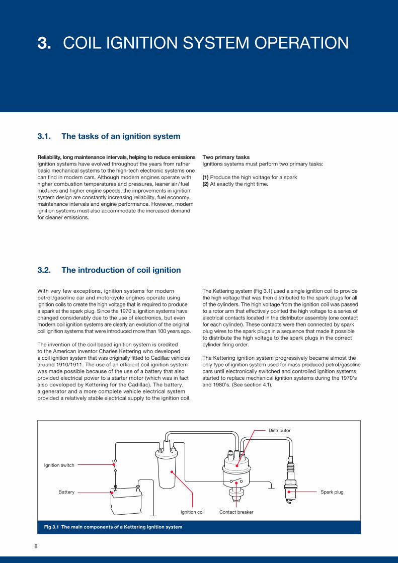
With very few exceptions, ignition systems for modern petrol /gasoline car and motorcycle engines operate using ignition coils to create the high voltage that is required to produce a spark at the spark plug. Since the 1970’s, ignition systems have changed considerably due to the use of electronics, but even modern coil ignition systems are clearly an evolution of the original coil ignition systems that were introduced more than 100 years ago.
The invention of the coil based ignition system is credited to the American inventor Charles Kettering who developed a coil ignition system that was originally fitted to Cadillac vehicles around 1910/1911. The use of an efficient coil ignition system was made possible because of the use of a battery that also provided electrical power to a starter motor (which was in fact also developed by Kettering for the Cadillac). The battery, a generator and a more complete vehicle electrical system provided a relatively stable electrical supply to the ignition coil.
The Kettering system (Fig 3.1) used a single ignition coil to provide the high voltage that was then distributed to the spark plugs for all of the cylinders. The high voltage from the ignition coil was passed to a rotor arm that effectively pointed the high voltage to a series of electrical contacts located in the distributor assembly (one contact for each cylinder). These contacts were then connected by spark plug wires to the spark plugs in a sequence that made it possible to distribute the high voltage to the spark plugs in the correct cylinder firing order.
The Kettering ignition system progressively became almost the only type of ignition system used for mass produced petrol /gasoline cars until electronically switched and controlled ignition systems started to replace mechanical ignition systems during the 1970’s and 1980’s. (See section 4.1).
Ignition switch
Fig 3.1 The main components of a Kettering ignition system
Battery
Contact breaker
Spark plug
Distributor
Ignition coil
8
3. COIL IGNITION SYSTEM OPERATION
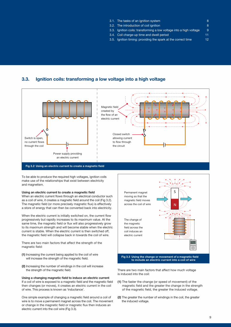
Fig 3.2 Using an electric current to create a magnetic field
Fig 3.3 Using the change or movement of a magnetic field to include an electric current into a coil of wire
N
SPermanent magnet moving so that the magnetic field moves across the coil of wire
The change of the magnetic field across the coil induces an electric current
3.3. Ignition coils: transforming a low voltage into a high voltage
To be able to produce the required high voltages, ignition coils make use of the relationships that exist between electricity and magnetism.
Using an electric current to create a magnetic fieldWhen an electric current flows through an electrical conductor such as a coil of wire, it creates a magnetic field around the coil (Fig 3.2). The magnetic field (or more precisely magnetic flux) is effectively a store of energy that can then be converted back into electricity.
When the electric current is initially switched on, the current flow progressively but rapidly increases to its maximum value. At the same time, the magnetic field or flux will also progressively grow to its maximum strength and will become stable when the electric current is stable. When the electric current is then switched off, the magnetic field will collapse back in towards the coil of wire.
There are two main factors that affect the strength of the magnetic field:
(1) Increasing the current being applied to the coil of wire will increase the strength of the magnetic field.
(2) Increasing the number of windings in the coil will increase the strength of the magnetic field.
Using a changing magnetic field to induce an electric currentIf a coil of wire is exposed to a magnetic field and the magnetic field then changes (or moves), it creates an electric current in the coil of wire. This process is known as ‘inductance’.
One simple example of changing a magnetic field around a coil of wire is to move a permanent magnet across the coil. The movement or change in the magnetic field or magnetic flux then induces an electric current into the coil wire (Fig 3.3).
There are two main factors that affect how much voltage is induced into the coil:
(1) The faster the change (or speed of movement) of the magnetic field and the greater the change in the strength of the magnetic field, the greater the induced voltage.
(2) The greater the number of windings in the coil, the greater the induced voltage.
Switch is open, no current flows through the coil
Power supply providing an electric current
Magnetic field created by the flow of an electric current
Closed switch allowing current to flow through the circuit
9
3.1. The tasks of an ignition system 8
3.2. The introduction of coil ignition 8
3.3. Ignition coils: transforming a low voltage into a high voltage 9
3.4. Coil charge-up time and dwell period 11
3.5. Ignition timing: providing the spark at the correct time 12
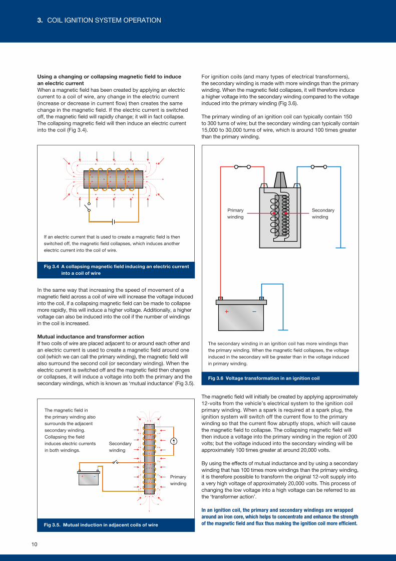
Fig 3.6 Voltage transformation in an ignition coil
Fig 3.4 A collapsing magnetic field inducing an electric current into a coil of wire
Fig 3.5. Mutual induction in adjacent coils of wire
The magnetic field in the primary winding also surrounds the adjacent secondary winding. Collapsing the field induces electric currents in both windings.
Secondary winding
Primary winding
The secondary winding in an ignition coil has more windings than the primary winding. When the magnetic field collapses, the voltage induced in the secondary will be greater than in the voltage induced in primary winding.
If an electric current that is used to create a magnetic field is then switched off, the magnetic field collapses, which induces another electric current into the coil of wire.
Primary winding
Secondary winding
Using a changing or collapsing magnetic field to induce an electric current When a magnetic field has been created by applying an electric current to a coil of wire, any change in the electric current (increase or decrease in current flow) then creates the same change in the magnetic field. If the electric current is switched off, the magnetic field will rapidly change; it will in fact collapse. The collapsing magnetic field will then induce an electric current into the coil (Fig 3.4).
In the same way that increasing the speed of movement of a magnetic field across a coil of wire will increase the voltage induced into the coil, if a collapsing magnetic field can be made to collapse more rapidly, this will induce a higher voltage. Additionally, a higher voltage can also be induced into the coil if the number of windings in the coil is increased.
Mutual inductance and transformer actionIf two coils of wire are placed adjacent to or around each other and an electric current is used to create a magnetic field around one coil (which we can call the primary winding), the magnetic field will also surround the second coil (or secondary winding). When the electric current is switched off and the magnetic field then changes or collapses, it will induce a voltage into both the primary and the secondary windings, which is known as ‘mutual inductance’ (Fig 3.5).
For ignition coils (and many types of electrical transformers), the secondary winding is made with more windings than the primary winding. When the magnetic field collapses, it will therefore induce a higher voltage into the secondary winding compared to the voltage induced into the primary winding (Fig 3.6).
The primary winding of an ignition coil can typically contain 150 to 300 turns of wire; but the secondary winding can typically contain 15,000 to 30,000 turns of wire, which is around 100 times greater than the primary winding.
The magnetic field will initially be created by applying approximately 12-volts from the vehicle’s electrical system to the ignition coil primary winding. When a spark is required at a spark plug, the ignition system will switch off the current flow to the primary winding so that the current flow abruptly stops, which will cause the magnetic field to collapse. The collapsing magnetic field will then induce a voltage into the primary winding in the region of 200 volts; but the voltage induced into the secondary winding will be approximately 100 times greater at around 20,000 volts.
By using the effects of mutual inductance and by using a secondary winding that has 100 times more windings than the primary winding, it is therefore possible to transform the original 12-volt supply into a very high voltage of approximately 20,000 volts. This process of changing the low voltage into a high voltage can be referred to as the ‘transformer action’.
In an ignition coil, the primary and secondary windings are wrapped around an iron core, which helps to concentrate and enhance the strength of the magnetic field and flux thus making the ignition coil more efficient.
10
3. COIL IGNITION SYSTEM OPERATION
Dw
ell t
ime
(ms)
Battery voltage (V)
Eng
ine
spee
d (R
PM
)
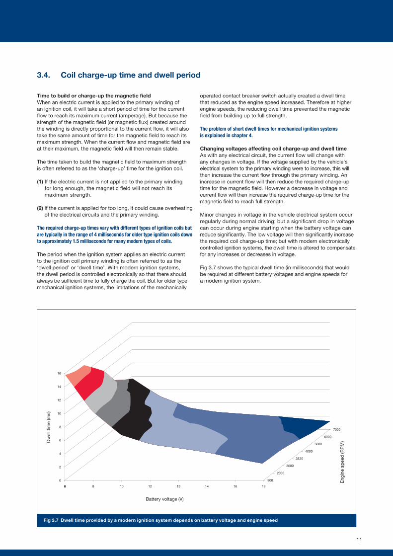
Fig 3.7 Dwell time provided by a modern ignition system depends on battery voltage and engine speed
66
16
14
12
10
8
6
4
2
0
8 10 12 13 14 16 19
800
2000
3000
3520
4000
5000
6000
7000
Battery voltage (V)
Dw
ell t
ime
(ms)
Eng
ine
spee
d (R
PM
)
3.4. Coil charge-up time and dwell period
Time to build or charge-up the magnetic fieldWhen an electric current is applied to the primary winding of an ignition coil, it will take a short period of time for the current flow to reach its maximum current (amperage). But because the strength of the magnetic field (or magnetic flux) created around the winding is directly proportional to the current flow, it will also take the same amount of time for the magnetic field to reach its maximum strength. When the current flow and magnetic field are at their maximum, the magnetic field will then remain stable.
The time taken to build the magnetic field to maximum strength is often referred to as the ‘charge-up’ time for the ignition coil.
(1) If the electric current is not applied to the primary winding for long enough, the magnetic field will not reach its maximum strength.
(2) If the current is applied for too long, it could cause overheating of the electrical circuits and the primary winding.
The required charge-up times vary with different types of ignition coils but are typically in the range of 4 milliseconds for older type ignition coils down to approximately 1.5 milliseconds for many modern types of coils.
The period when the ignition system applies an electric current to the ignition coil primary winding is often referred to as the ‘dwell period’ or ‘dwell time’. With modern ignition systems, the dwell period is controlled electronically so that there should always be sufficient time to fully charge the coil. But for older type mechanical ignition systems, the limitations of the mechanically
operated contact breaker switch actually created a dwell time that reduced as the engine speed increased. Therefore at higher engine speeds, the reducing dwell time prevented the magnetic field from building up to full strength.
The problem of short dwell times for mechanical ignition systems is explained in chapter 4.
Changing voltages affecting coil charge-up and dwell timeAs with any electrical circuit, the current flow will change with any changes in voltage. If the voltage supplied by the vehicle’s electrical system to the primary winding were to increase, this will then increase the current flow through the primary winding. An increase in current flow will then reduce the required charge-up time for the magnetic field. However a decrease in voltage and current flow will then increase the required charge-up time for the magnetic field to reach full strength.
Minor changes in voltage in the vehicle electrical system occur regularly during normal driving; but a significant drop in voltage can occur during engine starting when the battery voltage can reduce significantly. The low voltage will then significantly increase the required coil charge-up time; but with modern electronically controlled ignition systems, the dwell time is altered to compensate for any increases or decreases in voltage.
Fig 3.7 shows the typical dwell time (in milliseconds) that would be required at different battery voltages and engine speeds for a modern ignition system.
11
-60 -50 -40 -30 -20 -10 TDC 10 20 30 40 50 60
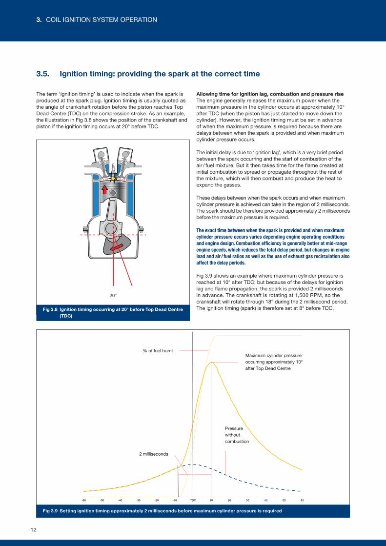
Fig 3.9 Setting ignition timing approximately 2 milliseconds before maximum cylinder pressure is required
20°
Fig 3.8 Ignition timing occurring at 20° before Top Dead Centre (TDC)
Pressure without combustion
2 milliseconds
Maximum cylinder pressure occurring approximately 10° after Top Dead Centre
% of fuel burnt
3.5. Ignition timing: providing the spark at the correct time
The term ‘ignition timing’ is used to indicate when the spark is produced at the spark plug. Ignition timing is usually quoted as the angle of crankshaft rotation before the piston reaches Top Dead Centre (TDC) on the compression stroke. As an example, the illustration in Fig 3.8 shows the position of the crankshaft and piston if the ignition timing occurs at 20° before TDC.
Allowing time for ignition lag, combustion and pressure riseThe engine generally releases the maximum power when the maximum pressure in the cylinder occurs at approximately 10° after TDC (when the piston has just started to move down the cylinder). However, the ignition timing must be set in advance of when the maximum pressure is required because there are delays between when the spark is provided and when maximum cylinder pressure occurs.
The initial delay is due to ‘ignition lag’, which is a very brief period between the spark occurring and the start of combustion of the air / fuel mixture. But it then takes time for the flame created at initial combustion to spread or propagate throughout the rest of the mixture, which will then combust and produce the heat to expand the gasses.
These delays between when the spark occurs and when maximum cylinder pressure is achieved can take in the region of 2 milliseconds.The spark should be therefore provided approximately 2 milliseconds before the maximum pressure is required.
The exact time between when the spark is provided and when maximum cylinder pressure occurs varies depending engine operating conditions and engine design. Combustion efficiency is generally better at mid-range engine speeds, which reduces the total delay period, but changes in engine load and air / fuel ratios as well as the use of exhaust gas recirculation also affect the delay periods.
Fig 3.9 shows an example where maximum cylinder pressure is reached at 10° after TDC; but because of the delays for ignition lag and flame propagation, the spark is provided 2 milliseconds in advance. The crankshaft is rotating at 1,500 RPM, so the crankshaft will rotate through 18° during the 2 millisecond period. The ignition timing (spark) is therefore set at 8° before TDC.
12
3. COIL IGNITION SYSTEM OPERATION
-60 -50 -40 -30 -20 -10 TDC 10 20 30 40 50 60
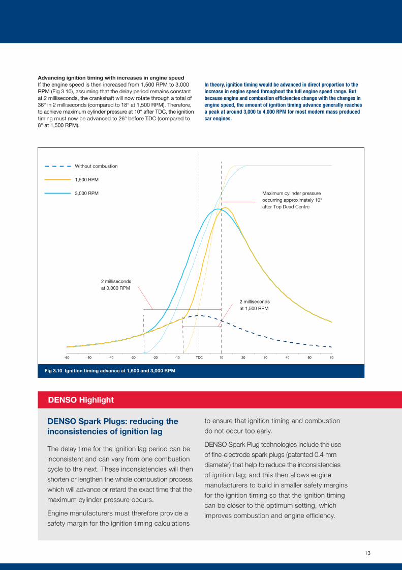
Fig 3.10 Ignition timing advance at 1,500 and 3,000 RPM
DENSO Highlight
Maximum cylinder pressure occurring approximately 10° after Top Dead Centre
2 milliseconds at 3,000 RPM
2 milliseconds at 1,500 RPM
Without combustion
1,500 RPM
3,000 RPM
DENSO Spark Plugs: reducing the inconsistencies of ignition lag
The delay time for the ignition lag period can be
inconsistent and can vary from one combustion
cycle to the next. These inconsistencies will then
shorten or lengthen the whole combustion process,
which will advance or retard the exact time that the
maximum cylinder pressure occurs.
Engine manufacturers must therefore provide a
safety margin for the ignition timing calculations
to ensure that ignition timing and combustion
do not occur too early.
DENSO Spark Plug technologies include the use
of fine-electrode spark plugs (patented 0.4 mm
diameter) that help to reduce the inconsistencies
of ignition lag; and this then allows engine
manufacturers to build in smaller safety margins
for the ignition timing so that the ignition timing
can be closer to the optimum setting, which
improves combustion and engine efficiency.
Advancing ignition timing with increases in engine speedIf the engine speed is then increased from 1,500 RPM to 3,000 RPM (Fig 3.10), assuming that the delay period remains constant at 2 milliseconds, the crankshaft will now rotate through a total of 36° in 2 milliseconds (compared to 18° at 1,500 RPM). Therefore, to achieve maximum cylinder pressure at 10° after TDC, the ignition timing must now be advanced to 26° before TDC (compared to 8° at 1,500 RPM).
In theory, ignition timing would be advanced in direct proportion to the increase in engine speed throughout the full engine speed range. But because engine and combustion efficiencies change with the changes in engine speed, the amount of ignition timing advance generally reaches a peak at around 3,000 to 4,000 RPM for most modern mass produced car engines.
13
Ignition timing dependent on engine load Although the optimal ignition timing is initially dependent on engine speed, the timing is also changed with changes in engine load.
When an engine is operating at light load conditions, which will usually mean that the throttle is only partially open, there will be a reduced mass of air entering the cylinder; therefore cylinder pressures will be lower than for full load conditions. Additionally, for older type engines and also on some modern engines, to help with economy and emissions, the air / fuel ratio can be leaner (less petrol / gasoline mixed with the air). The lower cylinder pressures and lean mixtures take longer to combust, which therefore requires the ignition timing to be advanced further to allow more time for combustion and to ensure that the maximum cylinder pressure still occurs at around 10° after TDC.
During light load conditions, the EGR system (exhaust gas recirculation system) can divert significant amounts of inert exhaust gas into the cylinder to help reduce combustion temperatures and harmful emissions. The use of EGR (see section 5.5) slows down the combustion process, which will again require an advance in the ignition timing.
Other operating conditions affecting ignition timingFor older vehicles equipped with mechanical type ignition systems (see section 4.1), optimal timing was usually dependent on just engine speed and load. However, modern electronically controlled ignition systems (that usually form part of engine management systems) alter the ignition timing depending on many engine operating conditions that include: engine speed, engine load, coolant temperature, air temperature, air / fuel ratio, throttle opening, fuel quality and EGR rate.
The different operating conditions are detected by various sensors that pass the operating information via electronic signals to the engine management computer. The computer then monitors the signals and provides the optimized ignition timing based on the information provided by the sensors.
Combustion knock sensingMany modern engines are also equipped with an additional sensor known as a ‘knock sensor’ or other knock sensing equipment. Minor changes can occur in the engine operation conditions that are not immediately detectable using the other sensors; but if the knock sensor detects any momentary or prolonged combustion knock, it passes this information to the engine management ECU. The ECU can then slightly retard the ignition timing until the knock is no longer present.
For those engines that were not equipped with all of the modern type sensors, the ignition computer was programmed with a pre-defined ignition map that might only embrace engine speed and load. However, to ensure that the ignition timing did not become over-advanced or retarded during critical operating conditions a safety margin would be included in the pre-defined timing map that might for example very slightly retard the ignition timing to prevent combustion knock.
Effects of advanced or retarded timingFor most engines and operating conditions, the ignition timing will occur in a range of just a few degrees before TDC at low engine speeds to around 30° or more before TDC at higher engine speeds. However, with older engines that were generally less efficient and had less efficient combustion chamber designs, the timing could often occur as much as 45° before TDC.
For some engine designs and with some operating conditions (that were usually emissions related), the ignition timing could be just after TDC.
(1) Optimal ignition timing. Optimal ignition timing is essential for efficient combustion, which will then lead to good engine performance, economy and cleaner emissions.
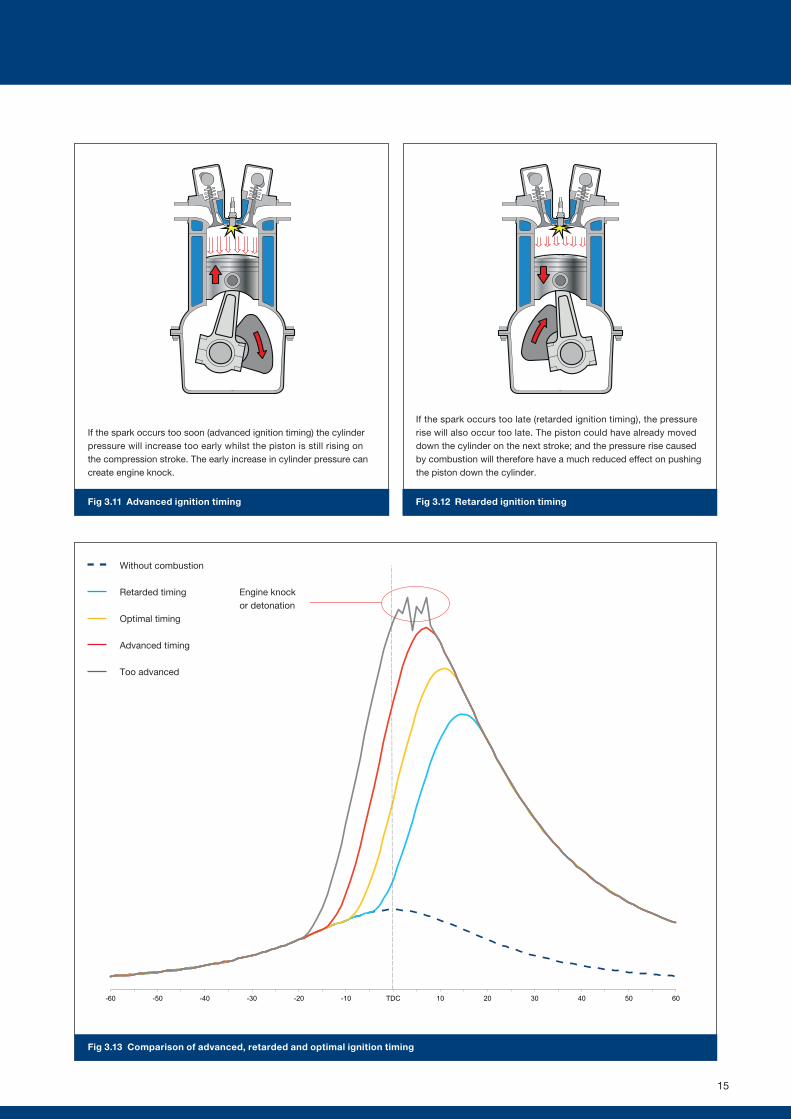
(2) Advanced or early ignition timing. Ignite the air / fuel mixture too early and the cylinder pressure and temperature will increase too soon. The pressure and temperature can become too high and create engine knock, especially if a significant part of the pressure rise occurs whilst the piston is still moving up the cylinder on the compression stroke (Fig 3.11).
(3) Retarded or late ignition timing. Ignite too late and the pressure rise caused by combustion will occur too late. The piston will have already moved down the cylinder further than during normal operation, therefore the force of the pressure rise pushing the piston down the cylinder will be reduced and less power will be developed (Fig 3.12).
Fig 3.13 shows a comparison of the effects of advanced, retarded and optimal ignition timing.
14
3. COIL IGNITION SYSTEM OPERATION
-60 -50 -40 -30 -20 -10 TDC 10 20 30 40 50 60
Fig 3.13 Comparison of advanced, retarded and optimal ignition timing
Fig 3.11 Advanced ignition timing
If the spark occurs too soon (advanced ignition timing) the cylinder pressure will increase too early whilst the piston is still rising on the compression stroke. The early increase in cylinder pressure can create engine knock.
Fig 3.12 Retarded ignition timing
If the spark occurs too late (retarded ignition timing), the pressure rise will also occur too late. The piston could have already moved down the cylinder on the next stroke; and the pressure rise caused by combustion will therefore have a much reduced effect on pushing the piston down the cylinder.
Without combustion
Retarded timing
Optimal timing
Advanced timing
Too advanced
Engine knock or detonation
15
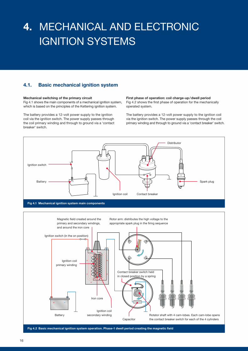
Fig 4.2 Basic mechanical ignition system operation. Phase-1 dwell period creating the magnetic field
Rotor arm: distributes the high voltage to the appropriate spark plug in the firing sequence
Magnetic field created around the primary and secondary windings, and around the iron core
Contact breaker switch held in closed position by a spring
Capacitor
Iron core
Battery
Ignition coil primary winding
Ignition switch (in the on position)
Ignition coil secondary winding Rotator shaft with 4 cam-lobes. Each cam-lobe opens
the contact breaker switch for each of the 4 cylinders
4.1. Basic mechanical ignition system
Mechanical switching of the primary circuitFig 4.1 shows the main components of a mechanical ignition system, which is based on the principles of the Kettering ignition system.
The battery provides a 12-volt power supply to the ignition coil via the ignition switch. The power supply passes through the coil primary winding and through to ground via a ‘contact breaker’ switch.
First phase of operation: coil charge-up / dwell periodFig 4.2 shows the first phase of operation for the mechanically operated system.
The battery provides a 12-volt power supply to the ignition coil via the ignition switch. The power supply passes through the coil primary winding and through to ground via a ‘contact breaker’ switch.
Ignition switch
Fig 4.1 Mechanical ignition system main components
Battery
Contact breaker
Spark plug
Ignition coil
Distributor
16
4. MECHANICAL AND ELECTRONIC IGNITION SYSTEMS
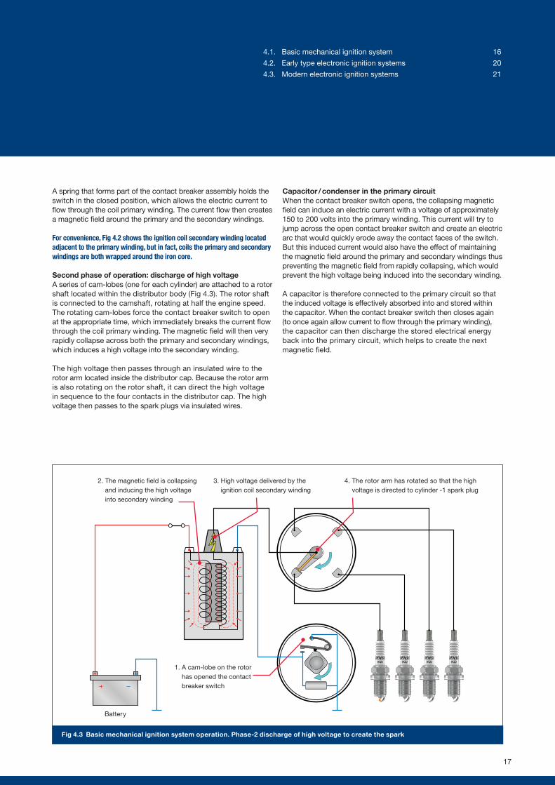
Fig 4.3 Basic mechanical ignition system operation. Phase-2 discharge of high voltage to create the spark
1. A cam-lobe on the rotor has opened the contact breaker switch
2. The magnetic field is collapsing and inducing the high voltage into secondary winding
3. High voltage delivered by the ignition coil secondary winding
4. The rotor arm has rotated so that the high voltage is directed to cylinder -1 spark plug
A spring that forms part of the contact breaker assembly holds the switch in the closed position, which allows the electric current to flow through the coil primary winding. The current flow then creates a magnetic field around the primary and the secondary windings.
For convenience, Fig 4.2 shows the ignition coil secondary winding located adjacent to the primary winding, but in fact, coils the primary and secondary windings are both wrapped around the iron core.
Second phase of operation: discharge of high voltage A series of cam-lobes (one for each cylinder) are attached to a rotor shaft located within the distributor body (Fig 4.3). The rotor shaft is connected to the camshaft, rotating at half the engine speed. The rotating cam-lobes force the contact breaker switch to open at the appropriate time, which immediately breaks the current flow through the coil primary winding. The magnetic field will then very rapidly collapse across both the primary and secondary windings, which induces a high voltage into the secondary winding.
The high voltage then passes through an insulated wire to the rotor arm located inside the distributor cap. Because the rotor arm is also rotating on the rotor shaft, it can direct the high voltage in sequence to the four contacts in the distributor cap. The high voltage then passes to the spark plugs via insulated wires.
Capacitor / condenser in the primary circuitWhen the contact breaker switch opens, the collapsing magnetic field can induce an electric current with a voltage of approximately 150 to 200 volts into the primary winding. This current will try to jump across the open contact breaker switch and create an electric arc that would quickly erode away the contact faces of the switch. But this induced current would also have the effect of maintaining the magnetic field around the primary and secondary windings thus preventing the magnetic field from rapidly collapsing, which would prevent the high voltage being induced into the secondary winding.
A capacitor is therefore connected to the primary circuit so that the induced voltage is effectively absorbed into and stored within the capacitor. When the contact breaker switch then closes again (to once again allow current to flow through the primary winding), the capacitor can then discharge the stored electrical energy back into the primary circuit, which helps to create the next magnetic field.
Battery
17
4.1. Basic mechanical ignition system 16
4.2. Early type electronic ignition systems 20
4.3. Modern electronic ignition systems 21
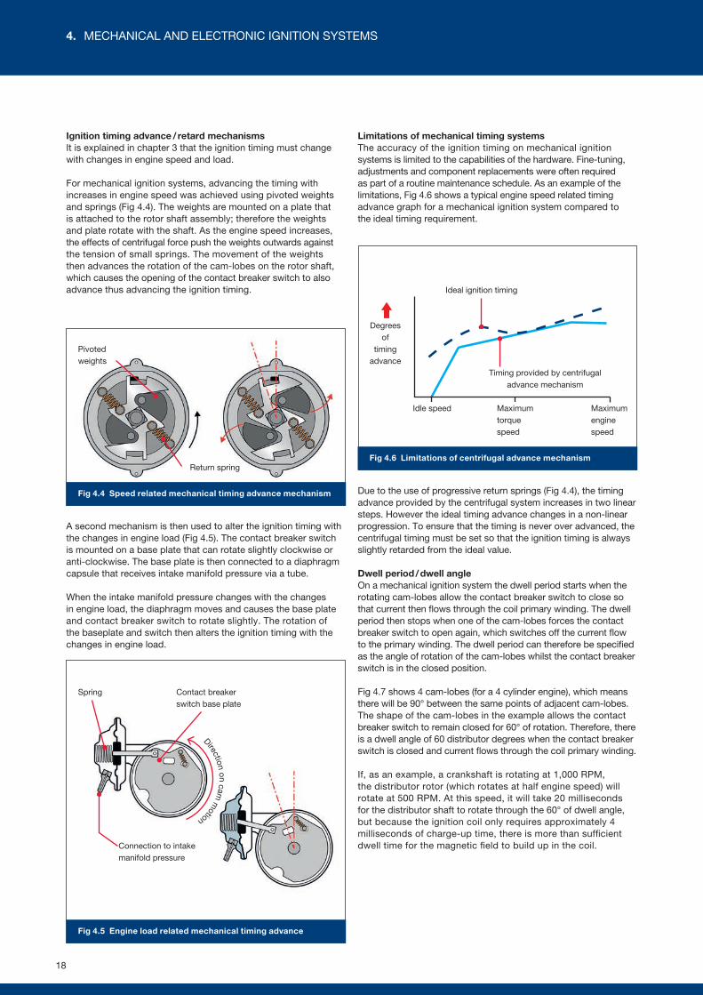
Fig 4.5 Engine load related mechanical timing advance
Fig 4.6 Limitations of centrifugal advance mechanism
Idle speed Maximum torque speed
Maximum engine speed
Ideal ignition timing
Timing provided by centrifugal advance mechanism
Degrees of
timing advance
Return spring
Fig 4.4 Speed related mechanical timing advance mechanism
Pivoted weights
Contact breaker switch base plate
Spring
Connection to intake manifold pressure
Direction on cam m
otion
Ignition timing advance / retard mechanismsIt is explained in chapter 3 that the ignition timing must change with changes in engine speed and load.
For mechanical ignition systems, advancing the timing with increases in engine speed was achieved using pivoted weights and springs (Fig 4.4). The weights are mounted on a plate that is attached to the rotor shaft assembly; therefore the weights and plate rotate with the shaft. As the engine speed increases, the effects of centrifugal force push the weights outwards against the tension of small springs. The movement of the weights then advances the rotation of the cam-lobes on the rotor shaft, which causes the opening of the contact breaker switch to also advance thus advancing the ignition timing.
A second mechanism is then used to alter the ignition timing with the changes in engine load (Fig 4.5). The contact breaker switch is mounted on a base plate that can rotate slightly clockwise or anti-clockwise. The base plate is then connected to a diaphragm capsule that receives intake manifold pressure via a tube.
When the intake manifold pressure changes with the changes in engine load, the diaphragm moves and causes the base plate and contact breaker switch to rotate slightly. The rotation of the baseplate and switch then alters the ignition timing with the changes in engine load.
Limitations of mechanical timing systemsThe accuracy of the ignition timing on mechanical ignition systems is limited to the capabilities of the hardware. Fine-tuning, adjustments and component replacements were often required as part of a routine maintenance schedule. As an example of the limitations, Fig 4.6 shows a typical engine speed related timing advance graph for a mechanical ignition system compared to the ideal timing requirement.
Due to the use of progressive return springs (Fig 4.4), the timing advance provided by the centrifugal system increases in two linear steps. However the ideal timing advance changes in a non-linear progression. To ensure that the timing is never over advanced, the centrifugal timing must be set so that the ignition timing is always slightly retarded from the ideal value.
Dwell period / dwell angleOn a mechanical ignition system the dwell period starts when the rotating cam-lobes allow the contact breaker switch to close so that current then flows through the coil primary winding. The dwell period then stops when one of the cam-lobes forces the contact breaker switch to open again, which switches off the current flow to the primary winding. The dwell period can therefore be specified as the angle of rotation of the cam-lobes whilst the contact breaker switch is in the closed position.
Fig 4.7 shows 4 cam-lobes (for a 4 cylinder engine), which means there will be 90° between the same points of adjacent cam-lobes. The shape of the cam-lobes in the example allows the contact breaker switch to remain closed for 60° of rotation. Therefore, there is a dwell angle of 60 distributor degrees when the contact breaker switch is closed and current flows through the coil primary winding.
If, as an example, a crankshaft is rotating at 1,000 RPM, the distributor rotor (which rotates at half engine speed) will rotate at 500 RPM. At this speed, it will take 20 milliseconds for the distributor shaft to rotate through the 60° of dwell angle, but because the ignition coil only requires approximately 4 milliseconds of charge-up time, there is more than sufficient dwell time for the magnetic field to build up in the coil.
18
4. MECHANICAL AND ELECTRONIC IGNITION SYSTEMS
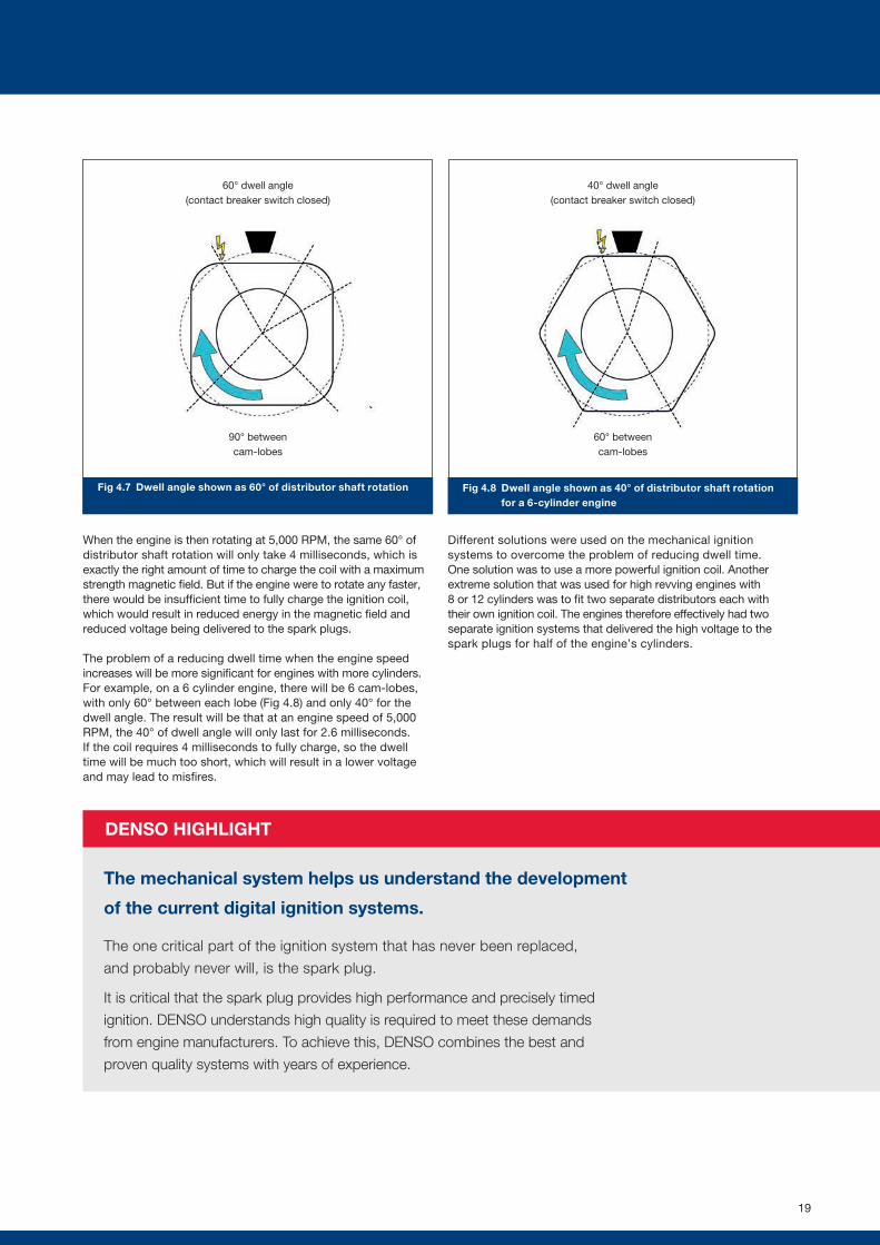
Fig 4.8 Dwell angle shown as 40° of distributor shaft rotation for a 6-cylinder engine
Fig 4.7 Dwell angle shown as 60° of distributor shaft rotation
60° dwell angle (contact breaker switch closed)
90° between cam-lobes
40° dwell angle (contact breaker switch closed)
60° between cam-lobes
DENSO HIGHLIGHT
The mechanical system helps us understand the development
of the current digital ignition systems.
The one critical part of the ignition system that has never been replaced,
and probably never will, is the spark plug.
It is critical that the spark plug provides high performance and precisely timed
ignition. DENSO understands high quality is required to meet these demands
from engine manufacturers. To achieve this, DENSO combines the best and
proven quality systems with years of experience.
When the engine is then rotating at 5,000 RPM, the same 60° of distributor shaft rotation will only take 4 milliseconds, which is exactly the right amount of time to charge the coil with a maximum strength magnetic field. But if the engine were to rotate any faster, there would be insufficient time to fully charge the ignition coil, which would result in reduced energy in the magnetic field and reduced voltage being delivered to the spark plugs.
The problem of a reducing dwell time when the engine speed increases will be more significant for engines with more cylinders. For example, on a 6 cylinder engine, there will be 6 cam-lobes, with only 60° between each lobe (Fig 4.8) and only 40° for the dwell angle. The result will be that at an engine speed of 5,000 RPM, the 40° of dwell angle will only last for 2.6 milliseconds. If the coil requires 4 milliseconds to fully charge, so the dwell time will be much too short, which will result in a lower voltage and may lead to misfires.
Different solutions were used on the mechanical ignition systems to overcome the problem of reducing dwell time. One solution was to use a more powerful ignition coil. Another extreme solution that was used for high revving engines with 8 or 12 cylinders was to fit two separate distributors each with their own ignition coil. The engines therefore effectively had two separate ignition systems that delivered the high voltage to the spark plugs for half of the engine’s cylinders.
19
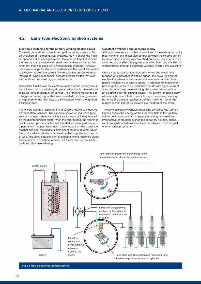
Fig 4.9 Basic electronic ignition system
Rotor arm: distributes the high voltage to the appropriate spark plug in the firing sequence
Battery
Ignition switch
Inductive sensor that sends a timing reference signal to the igniter
Igniter with transistor that functions as the switch, to turn the coil primary circuit on and off
Rotor shaft with timing reference rotor containing 4 reference points (one for each cylinder)
4.2. Early type electronic ignition systems
Electronic switching for the primary winding electric circuit The early generations of electronic ignition systems were in fact an evolution of the mechanical systems. Fig 4.8 shows the main components of an early generation electronic system that retained the mechanical advance and retard mechanisms as well as the rotor arm that was used on fully mechanical systems. However, one major change for electronic systems was the use of electronics to switch on and off the current flow through the primary winding instead of using a mechanical contact breaker switch that was inaccurate and required regular maintenance.
A transistor functions as the electronic switch for the primary circuit, and it forms part of a relatively simple amplifier that is often referred to as an ‘ignition module’ or ‘igniter’. The igniters responded to a trigger or timing signal that was provided by a timing sensor or signal generator that was usually located within the ignition distributor body.
There were two main types of timing sensors known as inductive and hall effect sensors. The example shows an inductive type sensor that used reference points (one for each cylinder) located on the distributor rotor shaft. When the rotor turned, the reference points moved past a small coil of wire that was wrapped around a permanent magnet. When each reference point moved past the magnet and coil, the magnetic field changed or fluctuated, which then induced a small electric current or electric pulse into the coil of wire. The electric pulses then provided a timing reference signal for the igniter, which then switched off the electric current to the ignition coil primary winding.
Constant dwell time and constant energyAlthough there were a number of variations of the early systems, for most variants, the igniter also controlled when the electric current to the primary winding was switched on as well as when it was switched off. In effect, the igniter controlled how long the electric current flowed through the primary winding, which is the dwell time.
Unlike mechanical ignition systems where the dwell time reduces with increases in engine speed, the dwell time on the electronic systems is maintained at a relatively constant time period irrespective of engine speed. In addition, to enable high power ignition coils to be used that operate with higher current flows through the primary winding, the igniters also contained an electronic current limiting device. The current limiters initially allow a high current flow to pass through the primary winding, but once the current reaches a defined maximum level, the current is then limited to prevent overheating of the circuit.
The use of a relatively constant dwell time combined with current limiting allows the energy of the magnetic field in the ignition coil to be almost constant irrespective of engine speed and irrespective of the normal changes in battery voltage. These electronic ignition systems were therefore referred to as ‘constant energy’ ignition systems.
20
4. MECHANICAL AND ELECTRONIC IGNITION SYSTEMS
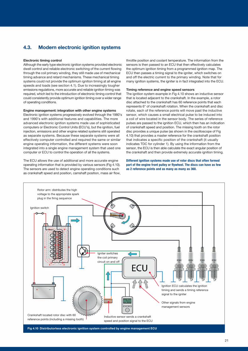
Fig 4.10 Distributorless electronic ignition system controlled by engine management ECU
Ignition switch
Crankshaft located rotor disc with 60 reference points (including a missing tooth)
Inductive sensor sends a crankshaft speed and position signal to the ECU
Ignition ECU calculates the ignition timing and sends a timing reference signal to the igniter
Other signals from engine management sensors
Igniter switches the coil primary circuit on and off
Rotor arm: distributes the high voltage to the appropriate spark plug in the firing sequence
4.3. Modern electronic ignition systems
Electronic timing controlAlthough the early type electronic ignition systems provided electronic dwell control and reliable electronic switching of the current flowing through the coil primary winding, they still made use of mechanical timing advance and retard mechanisms. These mechanical timing systems could not provide the optimum ignition timing at all engine speeds and loads (see section 4.1). Due to increasingly tougher emissions regulations, more accurate and reliable ignition timing was required, which led to the introduction of electronic timing control that could consistently provide optimum ignition timing over a wider range of operating conditions.
Engine management: integration with other engine systemsElectronic ignition systems progressively evolved through the 1980’s and 1990’s with additional features and capabilities. The more advanced electronic ignition systems made use of sophisticated computers or Electronic Control Units (ECU’s), but the ignition, fuel injection, emissions and other engine related systems still operated as separate systems. Because these separate systems were all effectively computer controlled and required the same or similar engine operating information, the different systems were soon integrated into a single engine management system that used one computer or ECU to control the operation of all the systems.
The ECU allows the use of additional and more accurate engine operating information that is provided by various sensors (Fig 4.10). The sensors are used to detect engine operating conditions such as crankshaft speed and position, camshaft position, mass air flow,
throttle position and coolant temperature. The information from the sensors is then passed to an ECU that then effectively calculates the optimum ignition timing from a programmed ignition map. The ECU then passes a timing signal to the igniter, which switches on and off the electric current to the primary winding. Note that for many ignition systems, the igniter is in fact integrated into the ECU.
Timing reference and engine speed sensorsThe ignition system example in Fig 4.10 shows an inductive sensor that is located adjacent to the crankshaft. In the example, a rotor disc attached to the crankshaft has 60 reference points that each represents 6° of crankshaft rotation. When the crankshaft and disc rotate, each of the reference points will move past the inductive sensor, which causes a small electrical pulse to be induced into a coil of wire located in the sensor body. The series of reference pulses are passed to the ignition ECU, which then has an indication of crankshaft speed and position. The missing tooth on the rotor disc provides a unique pulse (as shown in the oscilloscope of Fig 4.10) that provides a master reference for the crankshaft position that indicates a specific position of the crankshaft (it usually indicates TDC for cylinder 1). By using the information from the sensor, the ECU is then able calculate the exact angular position of the crankshaft and then provide extremely accurate ignition timing.
Different ignition systems made use of rotor discs that often formed part of the engine front pulley or flywheel. The discs can have as few as 2 reference points and as many as many as 360.
21
Crankshaft speed and
position
Ignitorand coil
assembly
Ignitorand coil
assembly
Ignitorand coil
assembly
Ignitorand coil
assembly
Batteryvoltage
Mass air�ow
Coolant + Airtemperature
Camshaftposition
Throttle position
Additionalinformation from
other sensors
ECU
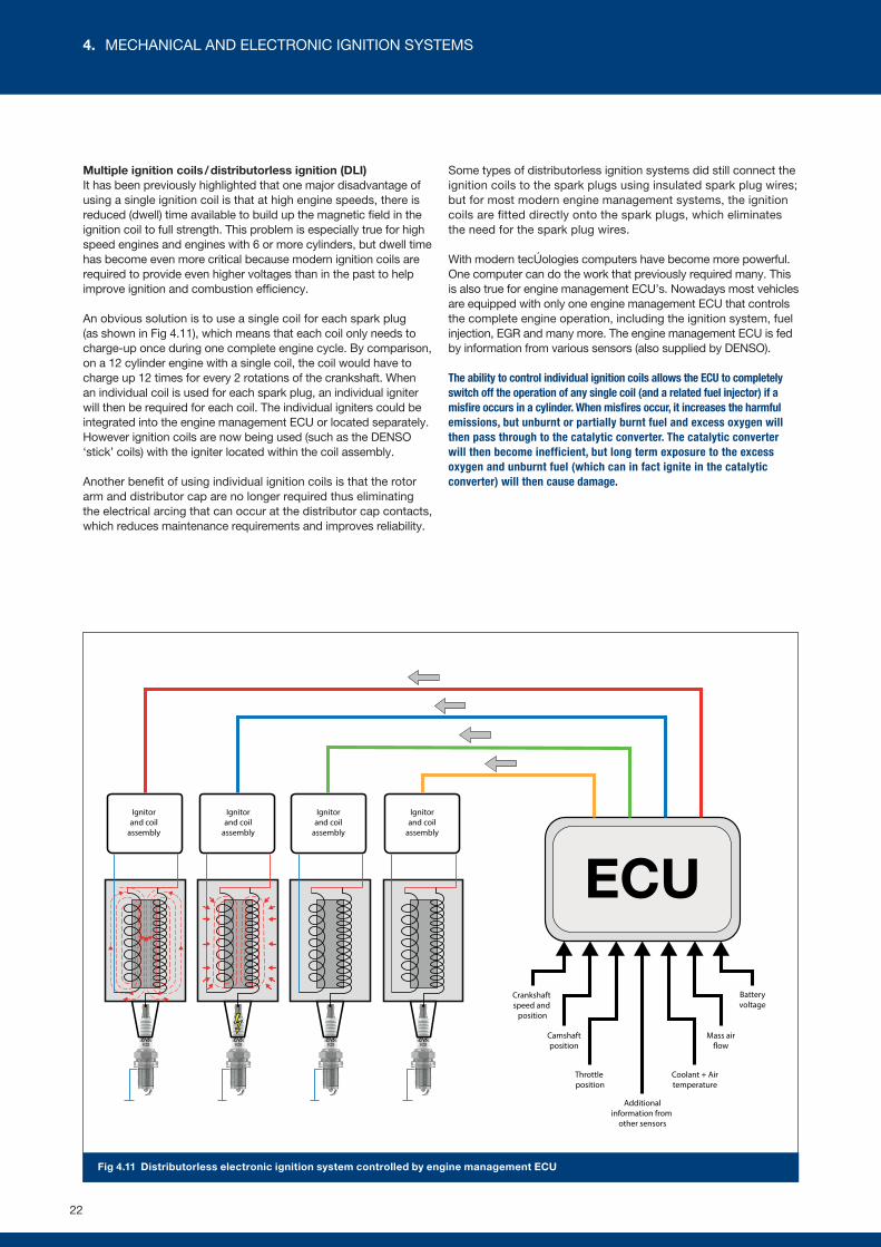
Fig 4.11 Distributorless electronic ignition system controlled by engine management ECU
Multiple ignition coils / distributorless ignition (DLI) It has been previously highlighted that one major disadvantage of using a single ignition coil is that at high engine speeds, there is reduced (dwell) time available to build up the magnetic field in the ignition coil to full strength. This problem is especially true for high speed engines and engines with 6 or more cylinders, but dwell time has become even more critical because modern ignition coils are required to provide even higher voltages than in the past to help improve ignition and combustion efficiency.
An obvious solution is to use a single coil for each spark plug (as shown in Fig 4.11), which means that each coil only needs to charge-up once during one complete engine cycle. By comparison, on a 12 cylinder engine with a single coil, the coil would have to charge up 12 times for every 2 rotations of the crankshaft. When an individual coil is used for each spark plug, an individual igniter will then be required for each coil. The individual igniters could be integrated into the engine management ECU or located separately. However ignition coils are now being used (such as the DENSO ‘stick’ coils) with the igniter located within the coil assembly.
Another benefit of using individual ignition coils is that the rotor arm and distributor cap are no longer required thus eliminating the electrical arcing that can occur at the distributor cap contacts, which reduces maintenance requirements and improves reliability.
Some types of distributorless ignition systems did still connect the ignition coils to the spark plugs using insulated spark plug wires; but for most modern engine management systems, the ignition coils are fitted directly onto the spark plugs, which eliminates the need for the spark plug wires.
With modern technologies computers have become more powerful. One computer can do the work that previously required many. This is also true for engine management ECU’s. Nowadays most vehicles are equipped with only one engine management ECU that controls the complete engine operation, including the ignition system, fuel injection, EGR and many more. The engine management ECU is fed by information from various sensors (also supplied by DENSO).
The ability to control individual ignition coils allows the ECU to completely switch off the operation of any single coil (and a related fuel injector) if a misfire occurs in a cylinder. When misfires occur, it increases the harmful emissions, but unburnt or partially burnt fuel and excess oxygen will then pass through to the catalytic converter. The catalytic converter will then become inefficient, but long term exposure to the excess oxygen and unburnt fuel (which can in fact ignite in the catalytic converter) will then cause damage.
22
4. MECHANICAL AND ELECTRONIC IGNITION SYSTEMS
DENSO HIGHLIGHT
Ignition coils
As well as being a leading manufacturer of spark plugs, DENSO is a long standing
leader in ignition technology, working in close cooperation with vehicle manufacturers
around the world. We developed the car industry’s first, compact, stick-type ignition
coil. DENSO also pioneered micro-sized driver circuits and diagonal inductive windings
for improved performance in a smaller space. These design breakthroughs, and others,
feature in DENSO’s Ignition Coils for the aftermarket, ensuring reliable, efficient ignition
performance on every journey.
23
+ +=
EG
EG
EG
EG
EG
EG
EG
EG
EG
EG
EG
EG
EG
EGEG
EG
EG
EG
EG
EG
EG
EG
EG
EG
EG
EG
EG
EG
AF
F
F
FF
F
F
F
F
F
F
F
FF
F
FF
F
F
F
F
F
F
F
F
F
FF
F
F
F
F
F
F
F
F
F
F
AA
AA
A
A
A
A
A
A
AA
A
A
A
A
A
A
A
AA
A
A
A
A
A
A
A
A
A
A
A
A
A
A
A
A
F
F F
F
FA
A
AA
AAA
A
F
F F
F
FA
A
AA
AAA
A
F
F F
FA
A
A
AAA
AA
AA
A
N2
N2
N2
N2
N2
N2
CO2 CO2
CO2
CO2
CO2
CO2
H2O
H2OH2O
H2O
H2O
H2O
N2
N2
N2
N2
N2
N2
CO2 CO2
CO2
CO2
CO2
CO2
H2O
H2OH2O
H2O
H2ON2
N2N2
CO2
CO2
CO2
H2OH2O
H2O
H2O
N2
N2
N2
N2
N2 N2
CO2
CO2
CO2
CO2
CO2
CO2
H2O
H2OH2O
H2O
H2O
H2O
N N
C
OO
HH
O
C5H12H
C5H12H
C5H12H
C5H12H
C5H12H
C5H12H
C5H12H
C5H12H
C5H12H
C5H12H
C5H12H
C5H12H
N2
N2
N2
N2
N2
N2
O2O2
O2
O2
O2
O2
O2
O2
O2
O2
N2
N2
N2
N2
N2
N2
O2O2
O2
O2
O2
O2
O2
O2
O2
O2
O2
N2
O2
O2 O2
O2
H
C C C C C
H
H
H H H
H
H H H H H
N N
O O
+ +=
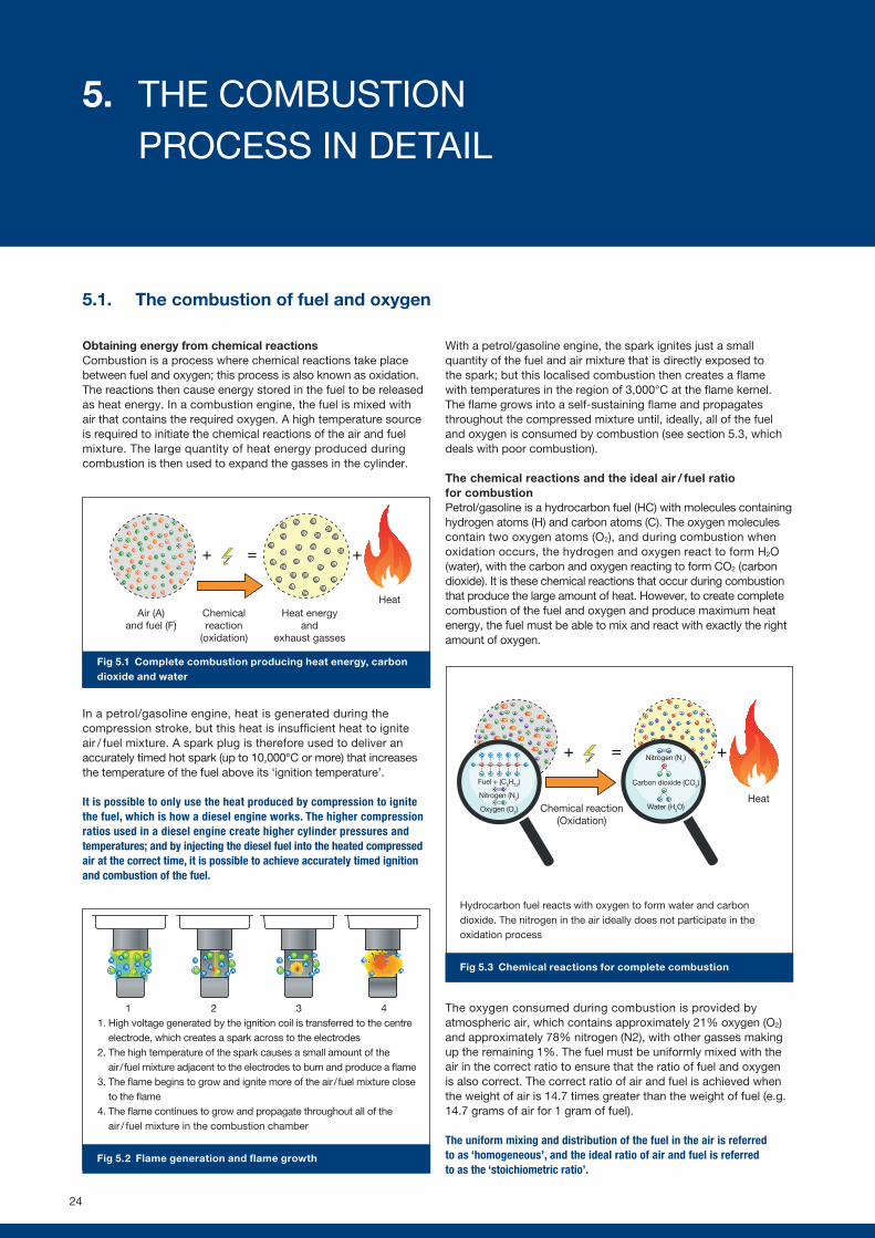
Fig 5.1 Complete combustion producing heat energy, carbon dioxide and water
Fig 5.2 Flame generation and flame growth
1 2 3 4
Fig 5.3 Chemical reactions for complete combustion
1. High voltage generated by the ignition coil is transferred to the centre electrode, which creates a spark across to the electrodes
2. The high temperature of the spark causes a small amount of the air / fuel mixture adjacent to the electrodes to burn and produce a flame
3. The flame begins to grow and ignite more of the air / fuel mixture close to the flame
4. The flame continues to grow and propagate throughout all of the air / fuel mixture in the combustion chamber
Hydrocarbon fuel reacts with oxygen to form water and carbon dioxide. The nitrogen in the air ideally does not participate in the oxidation process
5.1. The combustion of fuel and oxygen
Obtaining energy from chemical reactionsCombustion is a process where chemical reactions take place between fuel and oxygen; this process is also known as oxidation. The reactions then cause energy stored in the fuel to be released as heat energy. In a combustion engine, the fuel is mixed with air that contains the required oxygen. A high temperature source is required to initiate the chemical reactions of the air and fuel mixture. The large quantity of heat energy produced during combustion is then used to expand the gasses in the cylinder.
In a petrol/gasoline engine, heat is generated during the compression stroke, but this heat is insufficient heat to ignite air / fuel mixture. A spark plug is therefore used to deliver an accurately timed hot spark (up to 10,000°C or more) that increases the temperature of the fuel above its ‘ignition temperature’.
It is possible to only use the heat produced by compression to ignite the fuel, which is how a diesel engine works. The higher compression ratios used in a diesel engine create higher cylinder pressures and temperatures; and by injecting the diesel fuel into the heated compressed air at the correct time, it is possible to achieve accurately timed ignition and combustion of the fuel.
With a petrol/gasoline engine, the spark ignites just a small quantity of the fuel and air mixture that is directly exposed to the spark; but this localised combustion then creates a flame with temperatures in the region of 3,000°C at the flame kernel. The flame grows into a self-sustaining flame and propagates throughout the compressed mixture until, ideally, all of the fuel and oxygen is consumed by combustion (see section 5.3, which deals with poor combustion).
The chemical reactions and the ideal air / fuel ratio for combustionPetrol/gasoline is a hydrocarbon fuel (HC) with molecules containing hydrogen atoms (H) and carbon atoms (C). The oxygen molecules contain two oxygen atoms (O2), and during combustion when oxidation occurs, the hydrogen and oxygen react to form H2O (water), with the carbon and oxygen reacting to form CO2 (carbon dioxide). It is these chemical reactions that occur during combustion that produce the large amount of heat. However, to create complete combustion of the fuel and oxygen and produce maximum heat energy, the fuel must be able to mix and react with exactly the right amount of oxygen.
The oxygen consumed during combustion is provided by atmospheric air, which contains approximately 21% oxygen (O2) and approximately 78% nitrogen (N2), with other gasses making up the remaining 1%. The fuel must be uniformly mixed with the air in the correct ratio to ensure that the ratio of fuel and oxygen is also correct. The correct ratio of air and fuel is achieved when the weight of air is 14.7 times greater than the weight of fuel (e.g. 14.7 grams of air for 1 gram of fuel).
The uniform mixing and distribution of the fuel in the air is referred to as ‘homogeneous’, and the ideal ratio of air and fuel is referred to as the ‘stoichiometric ratio’.
Chemical reaction (Oxidation)
Air (A) and fuel (F)
Heat energy and
exhaust gasses
Chemical reaction
(oxidation)
Heat
Heat
Fuel + (C5H12)
Nitrogen (N2)
Nitrogen (N2)
Carbon dioxide (CO2)
Water (H2O) Oxygen (O2)
24
5. THE COMBUSTION PROCESS IN DETAIL
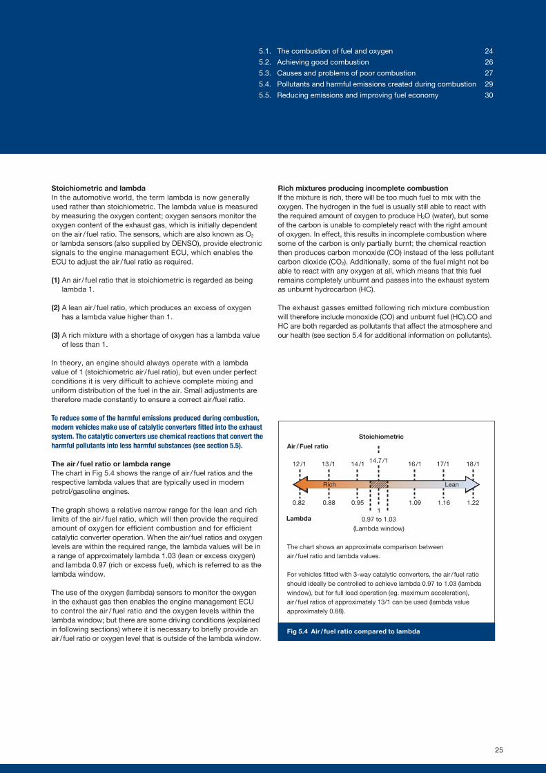
Fig 5.4 Air / fuel ratio compared to lambda
The chart shows an approximate comparison between air / fuel ratio and lambda values.
For vehicles fitted with 3-way catalytic converters, the air / fuel ratio should ideally be controlled to achieve lambda 0.97 to 1.03 (lambda window), but for full load operation (eg. maximum acceleration), air / fuel ratios of approximately 13/1 can be used (lambda value approximately 0.88).
Stoichiometric
12 /1
0.82
Air / Fuel ratio
Rich Lean
13 /1
0.88
14 /1
0.95
16 /1
1.09
17/1
1.16
18 /1
1.22
14.7 /1
10.97 to 1.03
(Lambda window)
Lambda
25
Stoichiometric and lambdaIn the automotive world, the term lambda is now generally used rather than stoichiometric. The lambda value is measured by measuring the oxygen content; oxygen sensors monitor the oxygen content of the exhaust gas, which is initially dependent on the air / fuel ratio. The sensors, which are also known as O2 or lambda sensors (also supplied by DENSO), provide electronic signals to the engine management ECU, which enables the ECU to adjust the air / fuel ratio as required.
(1) An air / fuel ratio that is stoichiometric is regarded as being lambda 1.
(2) A lean air / fuel ratio, which produces an excess of oxygen has a lambda value higher than 1.
(3) A rich mixture with a shortage of oxygen has a lambda value of less than 1.
In theory, an engine should always operate with a lambda value of 1 (stoichiometric air / fuel ratio), but even under perfect conditions it is very difficult to achieve complete mixing and uniform distribution of the fuel in the air. Small adjustments are therefore made constantly to ensure a correct air /fuel ratio.
To reduce some of the harmful emissions produced during combustion, modern vehicles make use of catalytic converters fitted into the exhaust system. The catalytic converters use chemical reactions that convert the harmful pollutants into less harmful substances (see section 5.5).
The air / fuel ratio or lambda rangeThe chart in Fig 5.4 shows the range of air / fuel ratios and the respective lambda values that are typically used in modern petrol/gasoline engines.
The graph shows a relative narrow range for the lean and rich limits of the air / fuel ratio, which will then provide the required amount of oxygen for efficient combustion and for efficient catalytic converter operation. When the air / fuel ratios and oxygen levels are within the required range, the lambda values will be in a range of approximately lambda 1.03 (lean or excess oxygen) and lambda 0.97 (rich or excess fuel), which is referred to as the lambda window.
The use of the oxygen (lambda) sensors to monitor the oxygen in the exhaust gas then enables the engine management ECU to control the air / fuel ratio and the oxygen levels within the lambda window; but there are some driving conditions (explained in following sections) where it is necessary to briefly provide an air / fuel ratio or oxygen level that is outside of the lambda window.
Rich mixtures producing incomplete combustionIf the mixture is rich, there will be too much fuel to mix with the oxygen. The hydrogen in the fuel is usually still able to react with the required amount of oxygen to produce H2O (water), but some of the carbon is unable to completely react with the right amount of oxygen. In effect, this results in incomplete combustion where some of the carbon is only partially burnt; the chemical reaction then produces carbon monoxide (CO) instead of the less pollutant carbon dioxide (CO2). Additionally, some of the fuel might not be able to react with any oxygen at all, which means that this fuel remains completely unburnt and passes into the exhaust system as unburnt hydrocarbon (HC).
The exhaust gasses emitted following rich mixture combustion will therefore include monoxide (CO) and unburnt fuel (HC).CO and HC are both regarded as pollutants that affect the atmosphere and our health (see section 5.4 for additional information on pollutants).
5.1. The combustion of fuel and oxygen 24
5.2. Achieving good combustion 26
5.3. Causes and problems of poor combustion 27
5.4. Pollutants and harmful emissions created during combustion 29
5.5. Reducing emissions and improving fuel economy 30
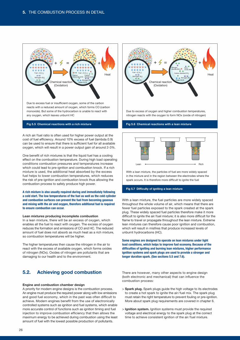
+ +=
N2
N2
N2
N2
N2
CO2
CO2
CO2
CO2
CO2
H2OH2O
H2O
H2O
H2O
CO2
N2
CO2
H2O
N2
N2
N2
N2
N2 N2
CO2
CO2
CO2
CO2
CO2
CO2
H2O
H2O
H2O
H2O
H2O
H2OC5H12H
C5H12HC5H12H
C5H12H
C5H12H
C5H12H
CO
CO
CO
C5H12H
C5H12H
N2
N2
N2
N2
N2
N2N2
O2
O2
O2
O2
O2
O2N2
N2 N2
N2
N2
N2
O2
O2
O2
O2
O2
O2
C5H12HN2
O2
O2
N2 O2
O2
H
C C C C C
H
H
H H H
H
H H H H H
N N
O O H H
O
C
O OC O
N N
C5H12HC5H12H
C5H12HC5H12H
C5H12H
C5H12H
C5H12H
C5H12H
C5H12H
C5H12H
C5H12H
C5H12H
C5H12HC5H12H
CO
CO
CO
CO
CO
CO
CO
H
C C C C C
H
H
H H H
H
H H H H H
F
F
F
F
F
F
F
FF
F
F
F
F
F
FF
AA A
AA
AAA
A
A
A
A
A
A
A
AA
A A
Fig 5.5 Chemical reactions with a rich mixture Fig 5.6 Chemical reactions with a lean mixture
Fig 5.7 Difficulty of igniting a lean mixture
+ +=C5H12H
N2
N2
N2
N2
N2
N2
CO2
CO2
CO2
CO2
CO2
H2O
H2O
H2O
H2O
H2O
CO2
N2
CO2
H2O
N2
N2
N2
N2
N2
N2
CO2
CO2
CO2
CO2
CO2
H2O
H2O
H2O
H2O
H2OH2O
C5H12H
N2
N2
N2
N2
N2
N2
N2
O2
O2
O2
O2
O2
O2
O2
O2
O2
O2
O2
O2
O2
O2
O2
O2
O2
O2
O2 N2
N2
N2
N2
N2
N2
O2
O2
O2
O2
O2
O2
O2
O2
O2
O2
O2
O2
O2
O2
O2
O2
O2
O2
O2
C5H12H
C5H12H
C5H12H
C5H12H
C5H12H
C5H12H
N2
N2
N2
N2
N2
N2
O2
O2
O2
O2
O2
O2
O2
O2
O2
O2
O2
O2
O2
O2
O2
O2
O2
O2
C5H12H
C5H12H
C5H12H
C5H12H
N2
N2
N2
N2
N2
N2
N2
O2
O2
O2
O2
O2
O2
O2
O2
O2
O2
O2
O2
O2
O2
O2
O2
O2
O2
O2
H
C C C C C
H
H
H H H
H
H H H H H
N N
O O
C
O O
H H
O
ON
O O
N
C5H12H
C5H12H
C5H12H
C5H12H
C5H12H
C5H12H
C5H12H
C5H12HC5H12H
N N
NO2
NO2
NO2
NO2
NO2
NO
NO
NO
NO
NO
A rich air / fuel ratio is often used for higher power output at the cost of fuel efficiency. Around 10% excess of fuel (lambda 0.9) can be used to ensure that there is sufficient fuel for all available oxygen, which will result in a power output gain of around 2-3%.
One benefit of rich mixtures is that the liquid fuel has a cooling effect on the combustion temperature. During high load operating conditions combustion pressures and temperatures increase which could lead to pre-ignition and combustion knock. If a rich mixture is used, the additional heat absorbed by the excess fuel helps to lower combustion temperatures, which reduces the risk of pre-ignition and combustion knock thus allowing the combustion process to safely produce high power.
A rich mixture is also usually required during and immediately following a cold start. The low temperatures of the fuel as well as the cold cylinder and combustion surfaces can prevent the fuel from becoming gaseous and mixing with the air and oxygen, therefore additional fuel is required to ensure combustion can occur.
Lean mixtures producing incomplete combustionIn a lean mixture, there will be an excess of oxygen, which enables all the fuel to react with oxygen. The excess of oxygen reduces the formation and emissions of CO and HC. The reduced amount of fuel does not absorb as much heat as a rich mixture, so combustion temperatures will be higher.
The higher temperatures then cause the nitrogen in the air to react with the excess of available oxygen, which forms oxides of nitrogen (NOx). Oxides of nitrogen are pollutants that are damaging to our health and to the environment.
With a lean mixture, the fuel particles are more widely spaced throughout the whole volume of air, which means that there are fewer fuel particles exposed to the spark created at the spark plug. These widely spaced fuel particles therefore make it more difficult to ignite the air / fuel mixture; it is also more difficult for the flame to travel or propagate throughout the lean mixture. Extreme lean mixtures can therefore cause poor ignition and combustion, which will result in misfires that produce increased levels of unburnt hydrocarbons (HC).
Some engines are designed to operate on lean mixtures under light load conditions, which helps to improve fuel economy. Because of the difficulties of igniting and burning lean mixtures, higher performance ignition systems and spark plugs are used to provide a stronger and longer duration spark. (See sections 5.5 and 7.6).
5.2. Achieving good combustion
Engine and combustion chamber designA priority for modern engine designs is the combustion process. An engine must produce the required power along with low emissions and good fuel economy, which in the past was often difficult to achieve. Modern engines benefit from the use of electronically controlled systems such as ignition and fuel systems, which enable more accurate control of functions such as ignition timing and fuel injection to improve combustion efficiency that then allows the maximum energy to be achieved during combustion using the least amount of fuel with the lowest possible production of pollutants.
There are however, many other aspects to engine design (both electronic and mechanical) that can influence the combustion process:
> Spark plug. Spark plugs guide the high voltage to its electrodes to create a hot spark to ignite the air / fuel mix. The spark plug must retain the right temperature to prevent fouling or pre-ignition. More about spark plug requirements are covered in chapter 6.
> Ignition system. Ignition systems must provide the required voltage and electrical energy to the spark plug at the correct time to achieve consistent ignition of the air / fuel mixture.
Due to excess fuel or insufficient oxygen, some of the carbon reacts with a reduced amount of oxygen, which forms CO (carbon monoxide). But some of the hydrocarbon is unable to react with any oxygen, which leaves unburnt HC
Due to excess of oxygen and higher combustion temperatures, nitrogen reacts with the oxygen to form NOx (oxide of nitrogen)
With a lean mixture, the particles of fuel are more widely spaced in the mixture and in the region between the electrodes where the spark occurs. It is therefore more difficult to ignite the fuel
Fuel + (C5H12)
Oxygen (O2)
Nitrogen (N2)
Fuel + (C5H12)
Oxygen (O2)
Nitrogen (N2)
Chemical reaction (Oxidation)
Chemical reaction (Oxidation)
Heat HeatFuel + (C5H12)
Carbon monoxide (CO)
Carbondioxide (CO2)
Carbon dioxide (CO2)
Nitrogen (N2)
Nitrogen (N2)
Water (H2O)Water (H2O)
Lean Rich
Nitrogen dioxide (NO2)
Nitric oxide (NO)
26
5. THE COMBUSTION PROCESS IN DETAIL
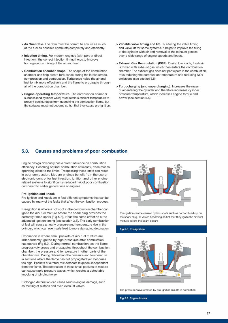
Fig 5.8 Pre-ignition
Fig 5.9 Engine knock
> Air / fuel ratio. The ratio must be correct to ensure as much of the fuel as possible combusts completely and efficiently.
> Injection timing. For modern engines (with port or direct injection), the correct injection timing helps to improve homogeneous mixing of the air and fuel.
> Combustion chamber shape. The shape of the combustion chamber can help create turbulence during the intake stroke, compression and combustion. Turbulence helps the air and fuel to mix more effectively and the flame to propagate through all of the combustion chamber.
> Engine operating temperature. The combustion chamber surfaces (and cylinder walls) must retain sufficient temperature to prevent cool surfaces from quenching the combustion flame, but the surfaces must not become so hot that they cause pre-ignition.
> Variable valve timing and lift. By altering the valve timing and valve lift for some systems, it helps to improve the filling of the cylinder with air and removal of the exhaust gasses over a wide range of engine speeds and loads.
> Exhaust Gas Recirculation (EGR). During low loads, fresh air is mixed with exhaust gas which then enters the combustion chamber. The exhaust gas does not participate in the combustion, thus reducing the combustion temperature and reducing NOx emissions (see section 5.5).
> Turbocharging (and supercharging). Increases the mass of air entering the cylinder and therefore increases cylinder pressure/temperature, which increases engine torque and power (see section 5.5).
5.3. Causes and problems of poor combustion
Engine design obviously has a direct influence on combustion efficiency. Reaching optimal combustion efficiency, often means operating close to the limits. Trespassing these limits can result in poor combustion. Modern engines benefit from the use of electronic control for fuel injection, ignition and other engine related systems to significantly reduced risk of poor combustion compared to earlier generations of engines.
Pre-ignition and knockPre-ignition and knock are in fact different symptoms that can be caused by many of the faults that affect the combustion process.
Pre-ignition is where a hot spot in the combustion chamber can ignite the air / fuel mixture before the spark plug provides the correctly timed spark (Fig 5.8), it has the same effect as a too advanced ignition timing (see section 3.5). The early combustion of fuel will cause an early pressure and temperature rise in the cylinder, which can eventually lead to more damaging detonation.
Detonation is where small pockets of air / fuel mixture are independently ignited by high pressures after combustion has started (Fig 5.9). During normal combustion, as the flame progressively grows and propagates throughout the combustion chamber, the pressure and temperature in other parts of the chamber rise. During detonation the pressure and temperature in sections where the flame has not propagated yet, becomes too high. Pockets of air / fuel mix detonate (explode) independent from the flame. The detonation of these small pockets of mixture can cause rapid pressure waves, which creates a detectable knocking or pinging noise.
Prolonged detonation can cause serious engine damage, such as melting of pistons and even exhaust valves.
Pre-ignition can be caused by hot-spots such as carbon build-up on the spark plug, or valves becoming so hot that they ignite the air / fuel mixture before the spark occurs
The pressure wave created by pre-ignition results in detonation
27
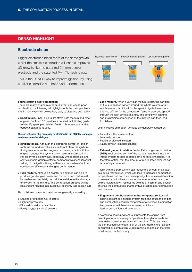
Faults causing poor combustionThere are many engine related faults that can cause poor combustion; the following list highlights only the main problems that in most cases will be relatively easy to diagnose and rectify.
> Spark plugs. Spark plug faults affect both modern and older engines. Section 10.3 provides a detailed fault finding guide to identify spark plug related faults. It is essential that the correct spark plug is used.
The correct spark plug can easily be identified in the DENSO e-catalogue on denso-am.eu/e-catalogue.
> Ignition timing. Although the electronic control of ignition systems on modern vehicles should not allow the ignition timing to alter from the programmed value, a fault with the engine management system could result in incorrect timing. For older vehicles however, especially with mechanical and early electronic ignition systems, component wear and incorrect setting of the ignition timing will have a noticeable effect on combustion efficiency and engine performance.
> Rich mixture. Although a slightly rich mixture can help to produce good engine power and torque, a rich mixture will be unable to completely burn all the fuel due to the shortage of oxygen in the mixture. The combustion process will be less efficient resulting in reduced fuel economy (see section 5.1).
Rich mixtures on modern vehicles are generally caused by:
> Leaking or dribbling fuel injectors> High fuel pressures> Blocked or restricted air filters> Faulty oxygen (lambda) sensors
> Lean mixture. When a very lean mixture exists, the particles of fuel are spaced widely around the whole volume of air, which means it is difficult for the spark to ignite the mixture. It is also difficult for the combustion flame to grow and spread through the lean air / fuel mixture. The difficulty in igniting and maintaining combustion of the mixture can then lead to misfires.
Lean mixtures on modern vehicles are generally caused by:
> Air leaks in the intake system> Low fuel pressure> Fouled or blocked injectors> Faulty oxygen (lambda) sensors
> Exhaust gas recirculation faults. Exhaust gas recirculation (EGR), recirculates some of the exhaust gas back into the intake system to help reduce some harmful emissions. It is therefore critical that the amount of recirculated exhaust gas is carefully controlled.
A fault with the EGR system can reduce the amount of exhaust gas being recirculated, which can lead to increased combustion temperatures that can then cause pre-ignition or even detonation. If however a fault allows an excessive amount of exhaust gas to be recirculated, it will restrict the volume of fresh air and oxygen entering the combustion chamber thus creating poor combustion and misfires.
> Engine and combustion chamber temperature. Loss of engine coolant or a cooling system fault can cause the engine and combustion chamber temperature to increase. Combustion temperatures will therefore increase, which can lead to pre-ignition and detonation.
If however a cooling system fault prevents the engine from reaching normal operating temperature, the cylinder walls and combustion chamber surfaces will be colder. This can quench the combustion flame before all of the air / fuel mixture has been consumed by combustion. A cold running engine can therefore result in poor fuel efficiency.
DENSO HIGHLIGHT
Electrode shape
Bigger electrodes block more of the flame growth,
whilst the smallest electrodes will enable improved
3D growth, like the patented 0.4 mm centre
electrode and the patented Twin Tip technology.
This is the DENSO way to improve ignition; by using
smaller electrodes and improved performance.
Improved flame growthReduced flame growth Optimal flame growth
28
5. THE COMBUSTION PROCESS IN DETAIL
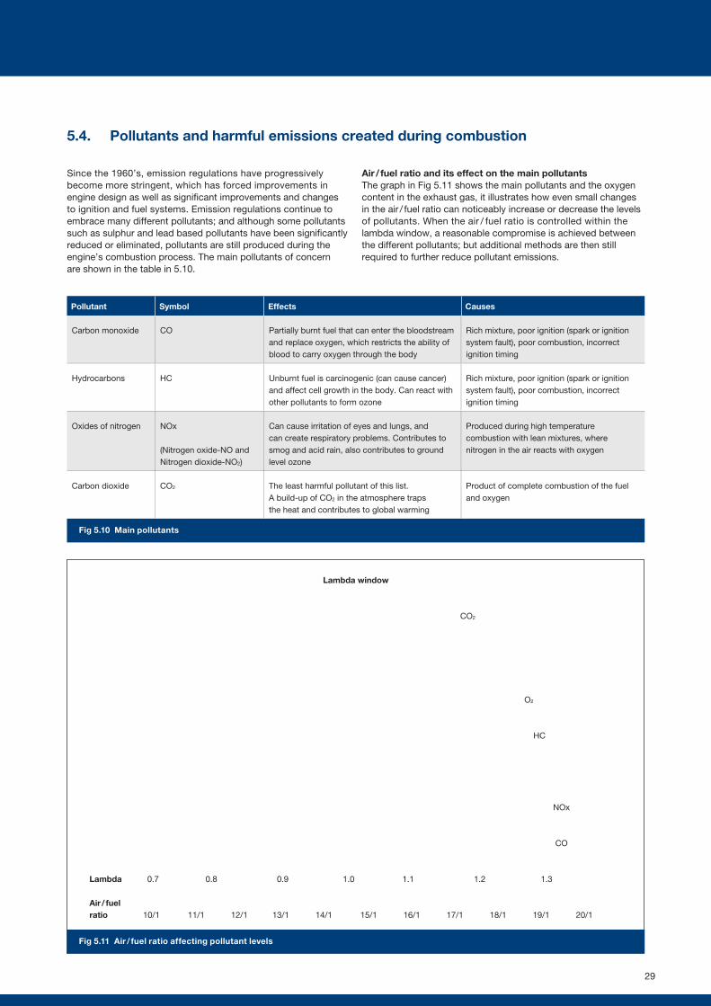
5.4. Pollutants and harmful emissions created during combustion
Since the 1960’s, emission regulations have progressively become more stringent, which has forced improvements in engine design as well as significant improvements and changes to ignition and fuel systems. Emission regulations continue to embrace many different pollutants; and although some pollutants such as sulphur and lead based pollutants have been significantly reduced or eliminated, pollutants are still produced during the engine’s combustion process. The main pollutants of concern are shown in the table in 5.10.
Air / fuel ratio and its effect on the main pollutants The graph in Fig 5.11 shows the main pollutants and the oxygen content in the exhaust gas, it illustrates how even small changes in the air / fuel ratio can noticeably increase or decrease the levels of pollutants. When the air / fuel ratio is controlled within the lambda window, a reasonable compromise is achieved between the different pollutants; but additional methods are then still required to further reduce pollutant emissions.
Fig 5.10 Main pollutants
Pollutant Symbol Effects Causes
Carbon monoxide CO Partially burnt fuel that can enter the bloodstream and replace oxygen, which restricts the ability of blood to carry oxygen through the body
Rich mixture, poor ignition (spark or ignition system fault), poor combustion, incorrect ignition timing
Hydrocarbons HC Unburnt fuel is carcinogenic (can cause cancer) and affect cell growth in the body. Can react with other pollutants to form ozone
Rich mixture, poor ignition (spark or ignition system fault), poor combustion, incorrect ignition timing
Oxides of nitrogen NOx
(Nitrogen oxide-NO and Nitrogen dioxide-NO2)
Can cause irritation of eyes and lungs, and can create respiratory problems. Contributes to smog and acid rain, also contributes to ground level ozone
Produced during high temperature combustion with lean mixtures, where nitrogen in the air reacts with oxygen
Carbon dioxide CO2 The least harmful pollutant of this list. A build-up of CO2 in the atmosphere traps the heat and contributes to global warming
Product of complete combustion of the fuel and oxygen
Lambda window
Fig 5.11 Air / fuel ratio affecting pollutant levels
Lambda 0.80.7 0.9 1.1 1.31.0 1.2
10/1 11/1 12/1 13/1 14/1 15/1 16/1 17/1 18/1 19/1 20/1Air / fuel ratio
CO2
CO
HC
NOx
O2
29
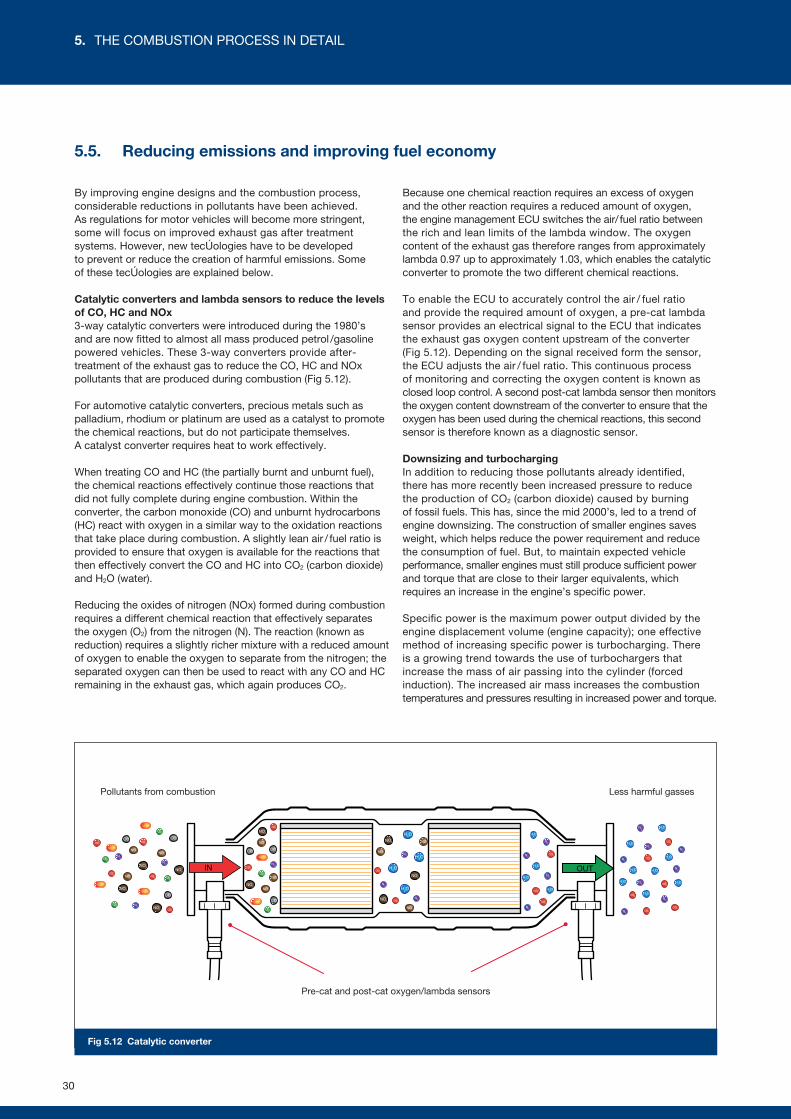
IN OUTH2O
H2O
H2O
CO2
N2
N2
H2O
H2O
H2O
N2
N2
CO2
CO2
H2O
CO2
N2
N2
H2O
H2O
H2O
N2
N2
CO2
CO2
H2O
CO2
N2
N2
H2O
H2O
H2O
N2
N2
CO2
CO2
H2O
H2O
CO2
CO CO
COCO2
CO2
CO2
CO2
CO
NO2
NO2NO2
NO2
NO2
NO2
NO2
NO
CO
CO2
CO2
NO2
NO NO
NO
NO
NO
NO
NOCO
CO2
CO2
NO2
NO
C5H12H
C5H12H
C5H12H
N2N2
N2
N2
N2
O2
C5H12H
N2O2
C5H12H
N2
O2
O2
C5H12H
O2
O2
Fig 5.12 Catalytic converter
5.5. Reducing emissions and improving fuel economy
By improving engine designs and the combustion process, considerable reductions in pollutants have been achieved. As regulations for motor vehicles will become more stringent, some will focus on improved exhaust gas after treatment systems. However, new technologies have to be developed to prevent or reduce the creation of harmful emissions. Some of these technologies are explained below.
Catalytic converters and lambda sensors to reduce the levels of CO, HC and NOx 3-way catalytic converters were introduced during the 1980’s and are now fitted to almost all mass produced petrol /gasoline powered vehicles. These 3-way converters provide after-treatment of the exhaust gas to reduce the CO, HC and NOx pollutants that are produced during combustion (Fig 5.12).
For automotive catalytic converters, precious metals such as palladium, rhodium or platinum are used as a catalyst to promote the chemical reactions, but do not participate themselves. A catalyst converter requires heat to work effectively.
When treating CO and HC (the partially burnt and unburnt fuel), the chemical reactions effectively continue those reactions that did not fully complete during engine combustion. Within the converter, the carbon monoxide (CO) and unburnt hydrocarbons (HC) react with oxygen in a similar way to the oxidation reactions that take place during combustion. A slightly lean air / fuel ratio is provided to ensure that oxygen is available for the reactions that then effectively convert the CO and HC into CO2 (carbon dioxide) and H2O (water).
Reducing the oxides of nitrogen (NOx) formed during combustion requires a different chemical reaction that effectively separates the oxygen (O2) from the nitrogen (N). The reaction (known as reduction) requires a slightly richer mixture with a reduced amount of oxygen to enable the oxygen to separate from the nitrogen; the separated oxygen can then be used to react with any CO and HC remaining in the exhaust gas, which again produces CO2.
Because one chemical reaction requires an excess of oxygen and the other reaction requires a reduced amount of oxygen, the engine management ECU switches the air/ fuel ratio between the rich and lean limits of the lambda window. The oxygen content of the exhaust gas therefore ranges from approximately lambda 0.97 up to approximately 1.03, which enables the catalytic converter to promote the two different chemical reactions.
To enable the ECU to accurately control the air / fuel ratio and provide the required amount of oxygen, a pre-cat lambda sensor provides an electrical signal to the ECU that indicates the exhaust gas oxygen content upstream of the converter (Fig 5.12). Depending on the signal received form the sensor, the ECU adjusts the air / fuel ratio. This continuous process of monitoring and correcting the oxygen content is known as closed loop control. A second post-cat lambda sensor then monitors the oxygen content downstream of the converter to ensure that the oxygen has been used during the chemical reactions, this second sensor is therefore known as a diagnostic sensor.
Downsizing and turbochargingIn addition to reducing those pollutants already identified, there has more recently been increased pressure to reduce the production of CO2 (carbon dioxide) caused by burning of fossil fuels. This has, since the mid 2000’s, led to a trend of engine downsizing. The construction of smaller engines saves weight, which helps reduce the power requirement and reduce the consumption of fuel. But, to maintain expected vehicle performance, smaller engines must still produce sufficient power and torque that are close to their larger equivalents, which requires an increase in the engine’s specific power.
Specific power is the maximum power output divided by the engine displacement volume (engine capacity); one effective method of increasing specific power is turbocharging. There is a growing trend towards the use of turbochargers that increase the mass of air passing into the cylinder (forced induction). The increased air mass increases the combustion temperatures and pressures resulting in increased power and torque.
Pre-cat and post-cat oxygen/lambda sensors
Less harmful gassesPollutants from combustion
30
5. THE COMBUSTION PROCESS IN DETAIL
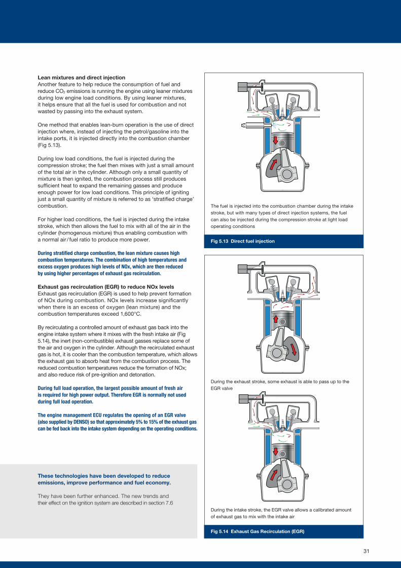
Fig 5.13 Direct fuel injection
Fig 5.14 Exhaust Gas Recirculation (EGR)
Lean mixtures and direct injection Another feature to help reduce the consumption of fuel and reduce CO2 emissions is running the engine using leaner mixtures during low engine load conditions. By using leaner mixtures, it helps ensure that all the fuel is used for combustion and not wasted by passing into the exhaust system.
One method that enables lean-burn operation is the use of direct injection where, instead of injecting the petrol/gasoline into the intake ports, it is injected directly into the combustion chamber (Fig 5.13).
During low load conditions, the fuel is injected during the compression stroke; the fuel then mixes with just a small amount of the total air in the cylinder. Although only a small quantity of mixture is then ignited, the combustion process still produces sufficient heat to expand the remaining gasses and produce enough power for low load conditions. This principle of igniting just a small quantity of mixture is referred to as ‘stratified charge’ combustion.
For higher load conditions, the fuel is injected during the intake stroke, which then allows the fuel to mix with all of the air in the cylinder (homogenous mixture) thus enabling combustion with a normal air / fuel ratio to produce more power.
During stratified charge combustion, the lean mixture causes high combustion temperatures. The combination of high temperatures and excess oxygen produces high levels of NOx, which are then reduced by using higher percentages of exhaust gas recirculation.
Exhaust gas recirculation (EGR) to reduce NOx levelsExhaust gas recirculation (EGR) is used to help prevent formation of NOx during combustion. NOx levels increase significantly when there is an excess of oxygen (lean mixture) and the combustion temperatures exceed 1,600°C.
By recirculating a controlled amount of exhaust gas back into the engine intake system where it mixes with the fresh intake air (Fig 5.14), the inert (non-combustible) exhaust gasses replace some of the air and oxygen in the cylinder. Although the recirculated exhaust gas is hot, it is cooler than the combustion temperature, which allows the exhaust gas to absorb heat from the combustion process. The reduced combustion temperatures reduce the formation of NOx; and also reduce risk of pre-ignition and detonation.
During full load operation, the largest possible amount of fresh air is required for high power output. Therefore EGR is normally not used during full load operation.
The engine management ECU regulates the opening of an EGR valve (also supplied by DENSO) so that approximately 5% to 15% of the exhaust gas can be fed back into the intake system depending on the operating conditions.
These technologies have been developed to reduce emissions, improve performance and fuel economy.
They have been further enhanced. The new trends and their effect on the ignition system are described in section 7.6
The fuel is injected into the combustion chamber during the intake stroke, but with many types of direct injection systems, the fuel can also be injected during the compression stroke at light load operating conditions
During the exhaust stroke, some exhaust is able to pass up to the EGR valve
During the intake stroke, the EGR valve allows a calibrated amount of exhaust gas to mix with the intake air
31
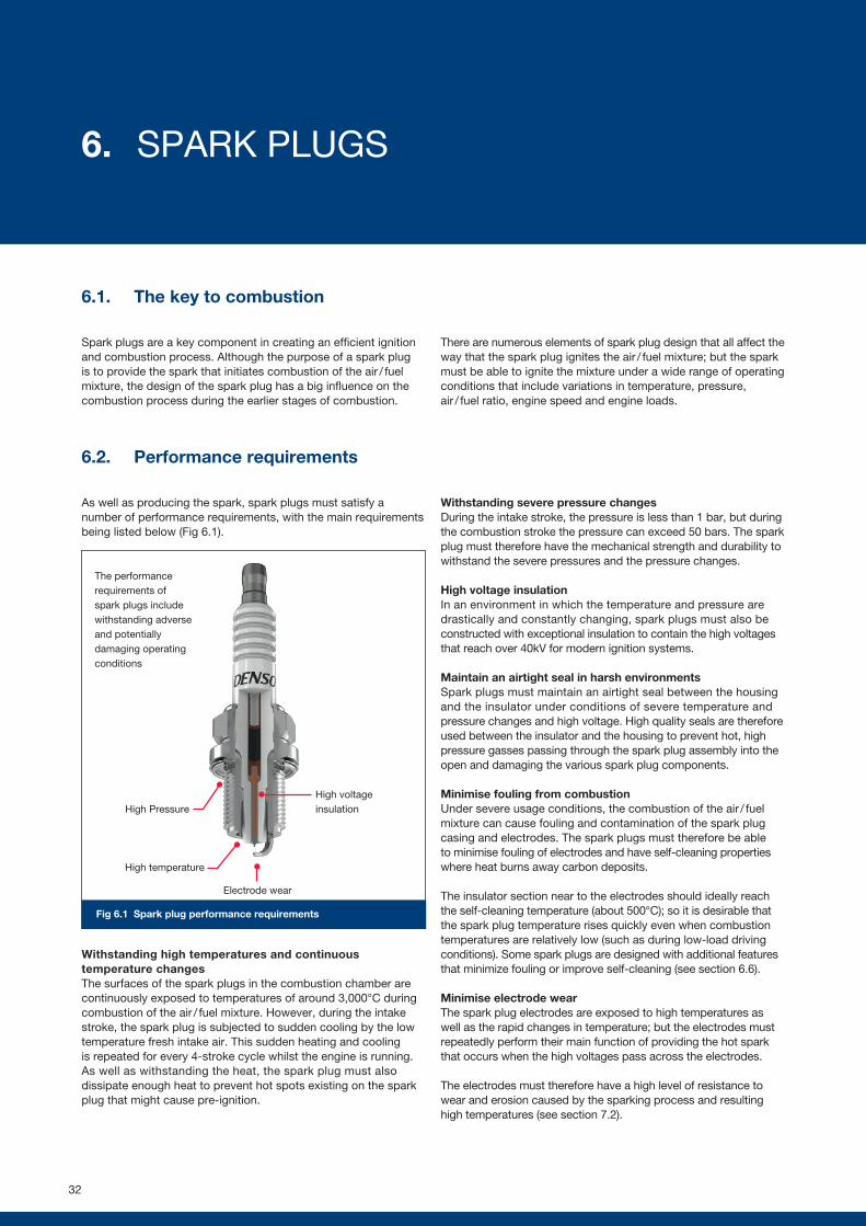
Fig 6.1 Spark plug performance requirements
6.1. The key to combustion
Spark plugs are a key component in creating an efficient ignition and combustion process. Although the purpose of a spark plug is to provide the spark that initiates combustion of the air / fuel mixture, the design of the spark plug has a big influence on the combustion process during the earlier stages of combustion.
There are numerous elements of spark plug design that all affect the way that the spark plug ignites the air / fuel mixture; but the spark must be able to ignite the mixture under a wide range of operating conditions that include variations in temperature, pressure, air / fuel ratio, engine speed and engine loads.
6.2. Performance requirements
As well as producing the spark, spark plugs must satisfy a number of performance requirements, with the main requirements being listed below (Fig 6.1).
Withstanding high temperatures and continuous temperature changesThe surfaces of the spark plugs in the combustion chamber are continuously exposed to temperatures of around 3,000°C during combustion of the air / fuel mixture. However, during the intake stroke, the spark plug is subjected to sudden cooling by the low temperature fresh intake air. This sudden heating and cooling is repeated for every 4-stroke cycle whilst the engine is running. As well as withstanding the heat, the spark plug must also dissipate enough heat to prevent hot spots existing on the spark plug that might cause pre-ignition.
Withstanding severe pressure changesDuring the intake stroke, the pressure is less than 1 bar, but during the combustion stroke the pressure can exceed 50 bars. The spark plug must therefore have the mechanical strength and durability to withstand the severe pressures and the pressure changes.
High voltage insulationIn an environment in which the temperature and pressure are drastically and constantly changing, spark plugs must also be constructed with exceptional insulation to contain the high voltages that reach over 40kV for modern ignition systems.
Maintain an airtight seal in harsh environmentsSpark plugs must maintain an airtight seal between the housing and the insulator under conditions of severe temperature and pressure changes and high voltage. High quality seals are therefore used between the insulator and the housing to prevent hot, high pressure gasses passing through the spark plug assembly into the open and damaging the various spark plug components.
Minimise fouling from combustionUnder severe usage conditions, the combustion of the air / fuel mixture can cause fouling and contamination of the spark plug casing and electrodes. The spark plugs must therefore be able to minimise fouling of electrodes and have self-cleaning properties where heat burns away carbon deposits.
The insulator section near to the electrodes should ideally reach the self-cleaning temperature (about 500°C); so it is desirable that the spark plug temperature rises quickly even when combustion temperatures are relatively low (such as during low-load driving conditions). Some spark plugs are designed with additional features that minimize fouling or improve self-cleaning (see section 6.6).
Minimise electrode wearThe spark plug electrodes are exposed to high temperatures as well as the rapid changes in temperature; but the electrodes must repeatedly perform their main function of providing the hot spark that occurs when the high voltages pass across the electrodes.
The electrodes must therefore have a high level of resistance to wear and erosion caused by the sparking process and resulting high temperatures (see section 7.2).
High voltage insulationHigh Pressure
High temperature
Electrode wear
The performance requirements of spark plugs include withstanding adverse and potentially damaging operating conditions
32
6. SPARK PLUGS
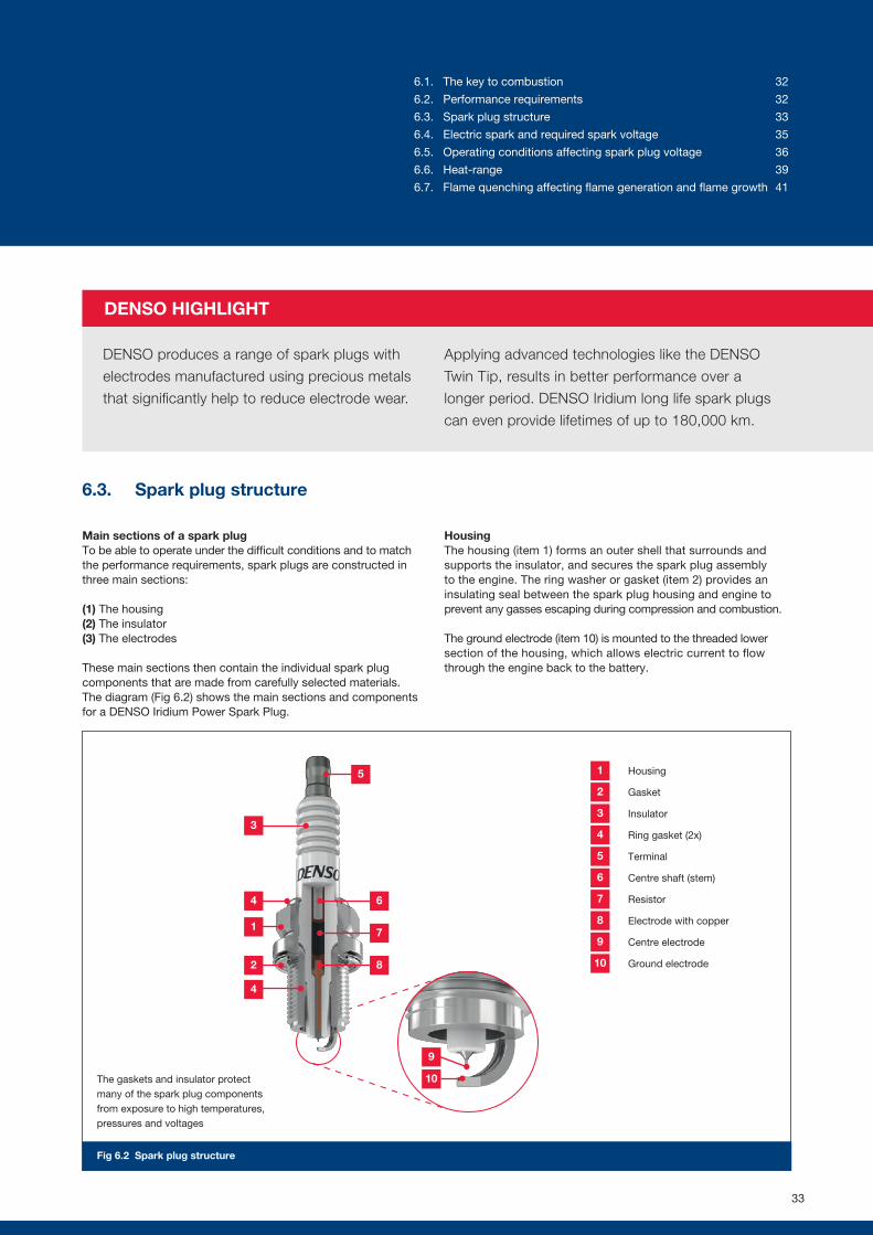
DENSO HIGHLIGHT
DENSO produces a range of spark plugs with
electrodes manufactured using precious metals
that significantly help to reduce electrode wear.
Applying advanced technologies like the DENSO
Twin Tip, results in better performance over a
longer period. DENSO Iridium long life spark plugs
can even provide lifetimes of up to 180,000 km.
Fig 6.2 Spark plug structure
6.3. Spark plug structure
Main sections of a spark plugTo be able to operate under the difficult conditions and to match the performance requirements, spark plugs are constructed in three main sections:
(1) The housing(2) The insulator(3) The electrodes
These main sections then contain the individual spark plug components that are made from carefully selected materials. The diagram (Fig 6.2) shows the main sections and components for a DENSO Iridium Power Spark Plug.
HousingThe housing (item 1) forms an outer shell that surrounds and supports the insulator, and secures the spark plug assembly to the engine. The ring washer or gasket (item 2) provides an insulating seal between the spark plug housing and engine to prevent any gasses escaping during compression and combustion.
The ground electrode (item 10) is mounted to the threaded lower section of the housing, which allows electric current to flow through the engine back to the battery.
The gaskets and insulator protect many of the spark plug components from exposure to high temperatures, pressures and voltages
3
4
9
10
4
1
2
5
6
7
8
Housing1
Centre shaft (stem)6
Gasket2
Resistor7
Insulator3
Electrode with copper8
Ring gasket (2x)4
Centre electrode9
Terminal5
Ground electrode10
33
6.1. The key to combustion 32
6.2. Performance requirements 32
6.3. Spark plug structure 33
6.4. Electric spark and required spark voltage 35
6.5. Operating conditions affecting spark plug voltage 36
6.6. Heat-range 39
6.7. Flame quenching affecting flame generation and flame growth 41
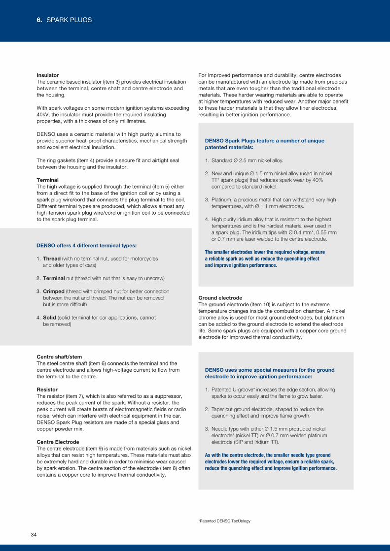
DENSO offers 4 different terminal types:
1. Thread (with no terminal nut, used for motorcycles and older types of cars)
2. Terminal nut (thread with nut that is easy to unscrew)
3. Crimped (thread with crimped nut for better connection between the nut and thread. The nut can be removed but is more difficult)
4. Solid (solid terminal for car applications, cannot be removed)
DENSO Spark Plugs feature a number of unique patented materials:
1. Standard Ø 2.5 mm nickel alloy.
2. New and unique Ø 1.5 mm nickel alloy (used in nickel TT* spark plugs) that reduces spark wear by 40% compared to standard nickel.
3. Platinum, a precious metal that can withstand very high temperatures, with Ø 1.1 mm electrodes.
4. High purity iridium alloy that is resistant to the highest temperatures and is the hardest material ever used in a spark plug. The iridium tips with Ø 0.4 mm*, 0.55 mm or 0.7 mm are laser welded to the centre electrode.
The smaller electrodes lower the required voltage, ensure a reliable spark as well as reduce the quenching effect and improve ignition performance.
DENSO uses some special measures for the ground electrode to improve ignition performance:
1. Patented U-groove* increases the edge section, allowing sparks to occur easily and the flame to grow faster.
2. Taper cut ground electrode, shaped to reduce the quenching effect and improve flame growth.
3. Needle type with either Ø 1.5 mm protruded nickel electrode* (nickel TT) or Ø 0.7 mm welded platinum electrode (SIP and Iridium TT).
As with the centre electrode, the smaller needle type ground electrodes lower the required voltage, ensure a reliable spark, reduce the quenching effect and improve ignition performance.
InsulatorThe ceramic based insulator (item 3) provides electrical insulation between the terminal, centre shaft and centre electrode and the housing.
With spark voltages on some modern ignition systems exceeding 40kV, the insulator must provide the required insulating properties, with a thickness of only millimetres.
DENSO uses a ceramic material with high purity alumina to provide superior heat-proof characteristics, mechanical strength and excellent electrical insulation.
The ring gaskets (item 4) provide a secure fit and airtight seal between the housing and the insulator.
Terminal The high voltage is supplied through the terminal (item 5) either from a direct fit to the base of the ignition coil or by using a spark plug wire/cord that connects the plug terminal to the coil. Different terminal types are produced, which allows almost any high-tension spark plug wire/cord or ignition coil to be connected to the spark plug terminal.
Centre shaft/stemThe steel centre shaft (item 6) connects the terminal and the centre electrode and allows high-voltage current to flow from the terminal to the centre.
Resistor The resistor (item 7), which is also referred to as a suppressor, reduces the peak current of the spark. Without a resistor, the peak current will create bursts of electromagnetic fields or radio noise, which can interfere with electrical equipment in the car. DENSO Spark Plug resistors are made of a special glass and copper powder mix.
Centre Electrode The centre electrode (item 9) is made from materials such as nickel alloys that can resist high temperatures. These materials must also be extremely hard and durable in order to minimise wear caused by spark erosion. The centre section of the electrode (item 8) often contains a copper core to improve thermal conductivity.
For improved performance and durability, centre electrodes can be manufactured with an electrode tip made from precious metals that are even tougher than the traditional electrode materials. These harder wearing materials are able to operate at higher temperatures with reduced wear. Another major benefit to these harder materials is that they allow finer electrodes, resulting in better ignition performance.
Ground electrode The ground electrode (item 10) is subject to the extreme temperature changes inside the combustion chamber. A nickel chrome alloy is used for most ground electrodes, but platinum can be added to the ground electrode to extend the electrode life. Some spark plugs are equipped with a copper core ground electrode for improved thermal conductivity.
*Patented DENSO Technology
34
6. SPARK PLUGS
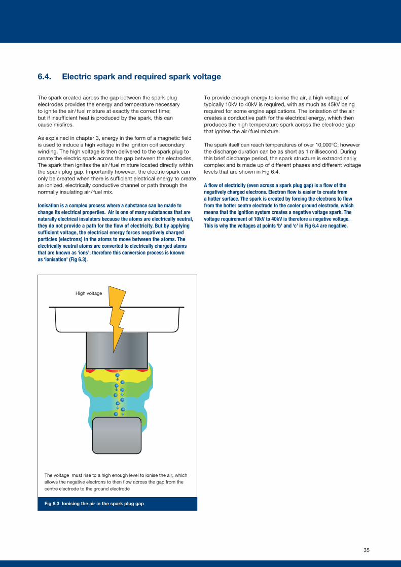
-
--
-
-
--
--
Fig 6.3 Ionising the air in the spark plug gap
6.4. Electric spark and required spark voltage
The spark created across the gap between the spark plug electrodes provides the energy and temperature necessary to ignite the air / fuel mixture at exactly the correct time; but if insufficient heat is produced by the spark, this can cause misfires.
As explained in chapter 3, energy in the form of a magnetic field is used to induce a high voltage in the ignition coil secondary winding. The high voltage is then delivered to the spark plug to create the electric spark across the gap between the electrodes. The spark then ignites the air / fuel mixture located directly within the spark plug gap. Importantly however, the electric spark can only be created when there is sufficient electrical energy to create an ionized, electrically conductive channel or path through the normally insulating air / fuel mix.
Ionisation is a complex process where a substance can be made to change its electrical properties. Air is one of many substances that are naturally electrical insulators because the atoms are electrically neutral, they do not provide a path for the flow of electricity. But by applying sufficient voltage, the electrical energy forces negatively charged particles (electrons) in the atoms to move between the atoms. The electrically neutral atoms are converted to electrically charged atoms that are known as ‘ions’; therefore this conversion process is known as ‘ionisation’ (Fig 6.3).
To provide enough energy to ionise the air, a high voltage of typically 10kV to 40kV is required, with as much as 45kV being required for some engine applications. The ionisation of the air creates a conductive path for the electrical energy, which then produces the high temperature spark across the electrode gap that ignites the air / fuel mixture.
The spark itself can reach temperatures of over 10,000°C; however the discharge duration can be as short as 1 millisecond. During this brief discharge period, the spark structure is extraordinarily complex and is made up of different phases and different voltage levels that are shown in Fig 6.4.
A flow of electricity (even across a spark plug gap) is a flow of the negatively charged electrons. Electron flow is easier to create from a hotter surface. The spark is created by forcing the electrons to flow from the hotter centre electrode to the cooler ground electrode, which means that the ignition system creates a negative voltage spark. The voltage requirement of 10kV to 40kV is therefore a negative voltage. This is why the voltages at points ‘b’ and ‘c’ in Fig 6.4 are negative.
High voltage
The voltage must rise to a high enough level to ionise the air, which allows the negative electrons to then flow across the gap from the centre electrode to the ground electrode
35
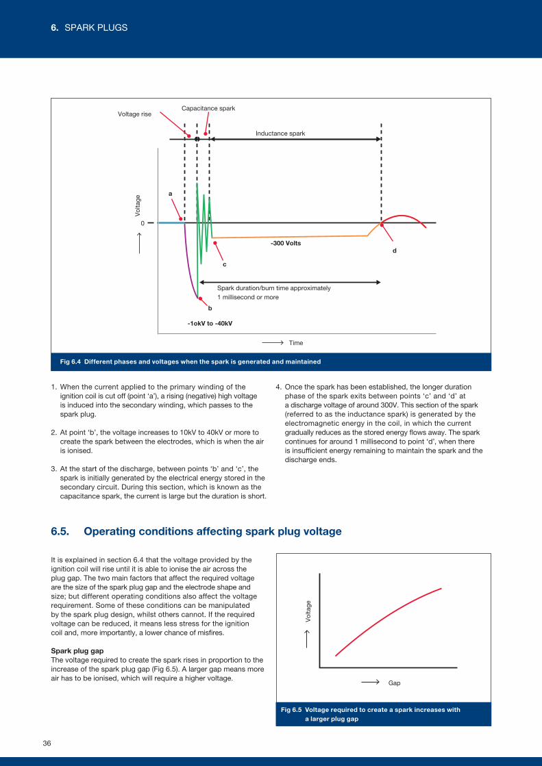
Fig 6.4 Different phases and voltages when the spark is generated and maintained
Vol
tage
Gap
Fig 6.5 Voltage required to create a spark increases with a larger plug gap
1. When the current applied to the primary winding of the ignition coil is cut off (point ‘a’), a rising (negative) high voltage is induced into the secondary winding, which passes to the spark plug.
2. At point ‘b’, the voltage increases to 10kV to 40kV or more to create the spark between the electrodes, which is when the air is ionised.
3. At the start of the discharge, between points ‘b’ and ‘c’, the spark is initially generated by the electrical energy stored in the secondary circuit. During this section, which is known as the capacitance spark, the current is large but the duration is short.
4. Once the spark has been established, the longer duration phase of the spark exits between points ‘c’ and ‘d’ at a discharge voltage of around 300V. This section of the spark (referred to as the inductance spark) is generated by the electromagnetic energy in the coil, in which the current gradually reduces as the stored energy flows away. The spark continues for around 1 millisecond to point ‘d’, when there is insufficient energy remaining to maintain the spark and the discharge ends.
6.5. Operating conditions affecting spark plug voltage
It is explained in section 6.4 that the voltage provided by the ignition coil will rise until it is able to ionise the air across the plug gap. The two main factors that affect the required voltage are the size of the spark plug gap and the electrode shape and size; but different operating conditions also affect the voltage requirement. Some of these conditions can be manipulated by the spark plug design, whilst others cannot. If the required voltage can be reduced, it means less stress for the ignition coil and, more importantly, a lower chance of misfires.
Spark plug gap The voltage required to create the spark rises in proportion to the increase of the spark plug gap (Fig 6.5). A larger gap means more air has to be ionised, which will require a higher voltage.
Time
Spark duration/burn time approximately 1 millisecond or more
-300 Volts
0
Vol
tage
-1okV to -40kV
Inductance spark
Capacitance sparkVoltage rise
b
c
d
a
36
6. SPARK PLUGS
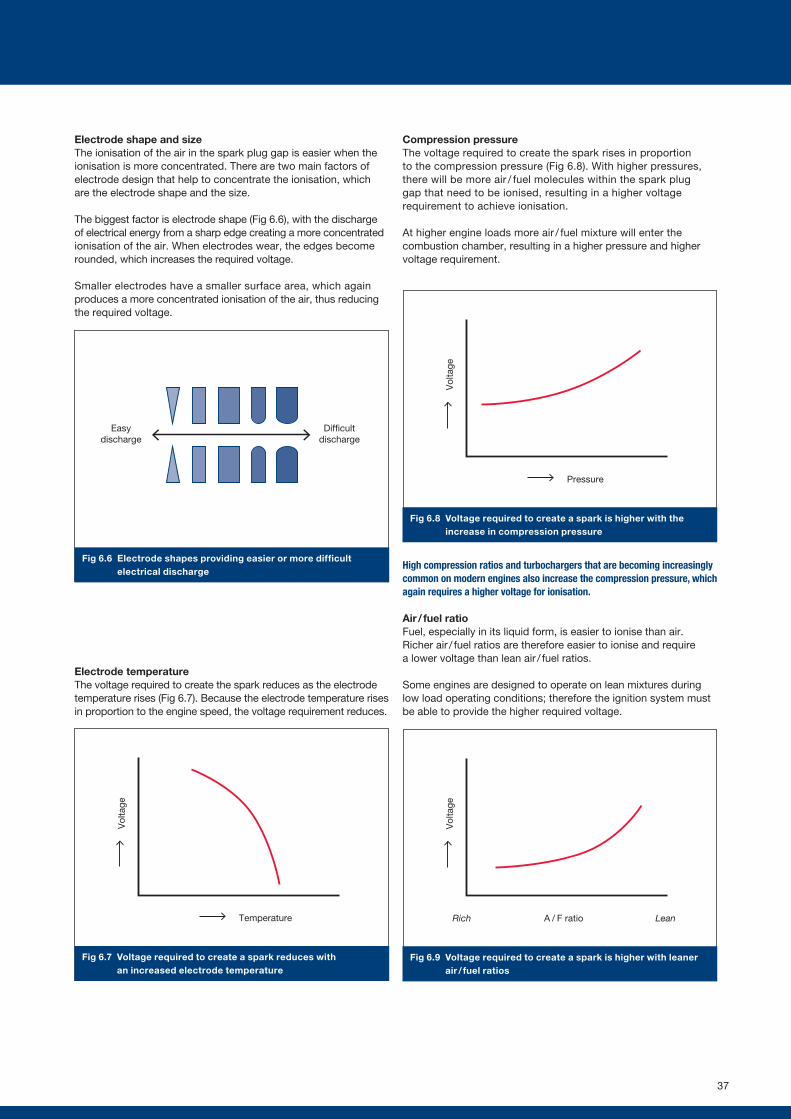
Easydischarge
Difficultdischarge
Fig 6.6 Electrode shapes providing easier or more difficult electrical discharge
Vol
tage
Temperature
Fig 6.7 Voltage required to create a spark reduces with an increased electrode temperature
Vol
tage
Pressure
Vol
tage
A / F ratioRich Lean
Fig 6.8 Voltage required to create a spark is higher with the increase in compression pressure
Fig 6.9 Voltage required to create a spark is higher with leaner air / fuel ratios
Electrode shape and sizeThe ionisation of the air in the spark plug gap is easier when the ionisation is more concentrated. There are two main factors of electrode design that help to concentrate the ionisation, which are the electrode shape and the size.
The biggest factor is electrode shape (Fig 6.6), with the discharge of electrical energy from a sharp edge creating a more concentrated ionisation of the air. When electrodes wear, the edges become rounded, which increases the required voltage.
Smaller electrodes have a smaller surface area, which again produces a more concentrated ionisation of the air, thus reducing the required voltage.
Electrode temperatureThe voltage required to create the spark reduces as the electrode temperature rises (Fig 6.7). Because the electrode temperature rises in proportion to the engine speed, the voltage requirement reduces.
Compression pressure The voltage required to create the spark rises in proportion to the compression pressure (Fig 6.8). With higher pressures, there will be more air / fuel molecules within the spark plug gap that need to be ionised, resulting in a higher voltage requirement to achieve ionisation.
At higher engine loads more air / fuel mixture will enter the combustion chamber, resulting in a higher pressure and higher voltage requirement.
High compression ratios and turbochargers that are becoming increasingly common on modern engines also increase the compression pressure, which again requires a higher voltage for ionisation.
Air / fuel ratioFuel, especially in its liquid form, is easier to ionise than air. Richer air / fuel ratios are therefore easier to ionise and require a lower voltage than lean air / fuel ratios.
Some engines are designed to operate on lean mixtures during low load operating conditions; therefore the ignition system must be able to provide the higher required voltage.
37
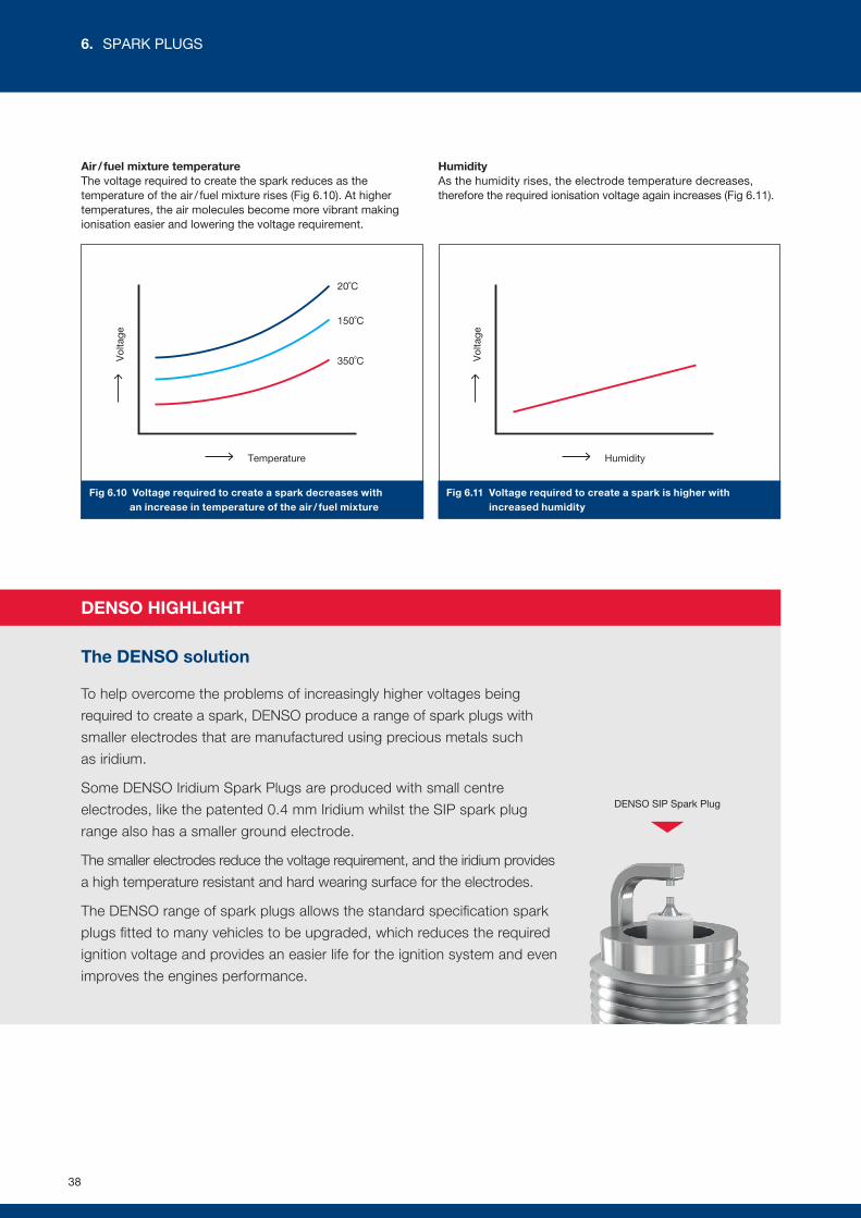
Vol
tage
Temperature
20˚C
150˚C
350˚C Vol
tage
Humidity
Fig 6.10 Voltage required to create a spark decreases with an increase in temperature of the air / fuel mixture
Fig 6.11 Voltage required to create a spark is higher with increased humidity
Air / fuel mixture temperature The voltage required to create the spark reduces as the temperature of the air / fuel mixture rises (Fig 6.10). At higher temperatures, the air molecules become more vibrant making ionisation easier and lowering the voltage requirement.
Humidity As the humidity rises, the electrode temperature decreases, therefore the required ionisation voltage again increases (Fig 6.11).
DENSO HIGHLIGHT
The DENSO solution
To help overcome the problems of increasingly higher voltages being
required to create a spark, DENSO produce a range of spark plugs with
smaller electrodes that are manufactured using precious metals such
as iridium.
Some DENSO Iridium Spark Plugs are produced with small centre
electrodes, like the patented 0.4 mm Iridium whilst the SIP spark plug
range also has a smaller ground electrode.
The smaller electrodes reduce the voltage requirement, and the iridium provides
a high temperature resistant and hard wearing surface for the electrodes.
The DENSO range of spark plugs allows the standard specification spark
plugs fitted to many vehicles to be upgraded, which reduces the required
ignition voltage and provides an easier life for the ignition system and even
improves the engines performance.
DENSO SIP Spark Plug
38
6. SPARK PLUGS
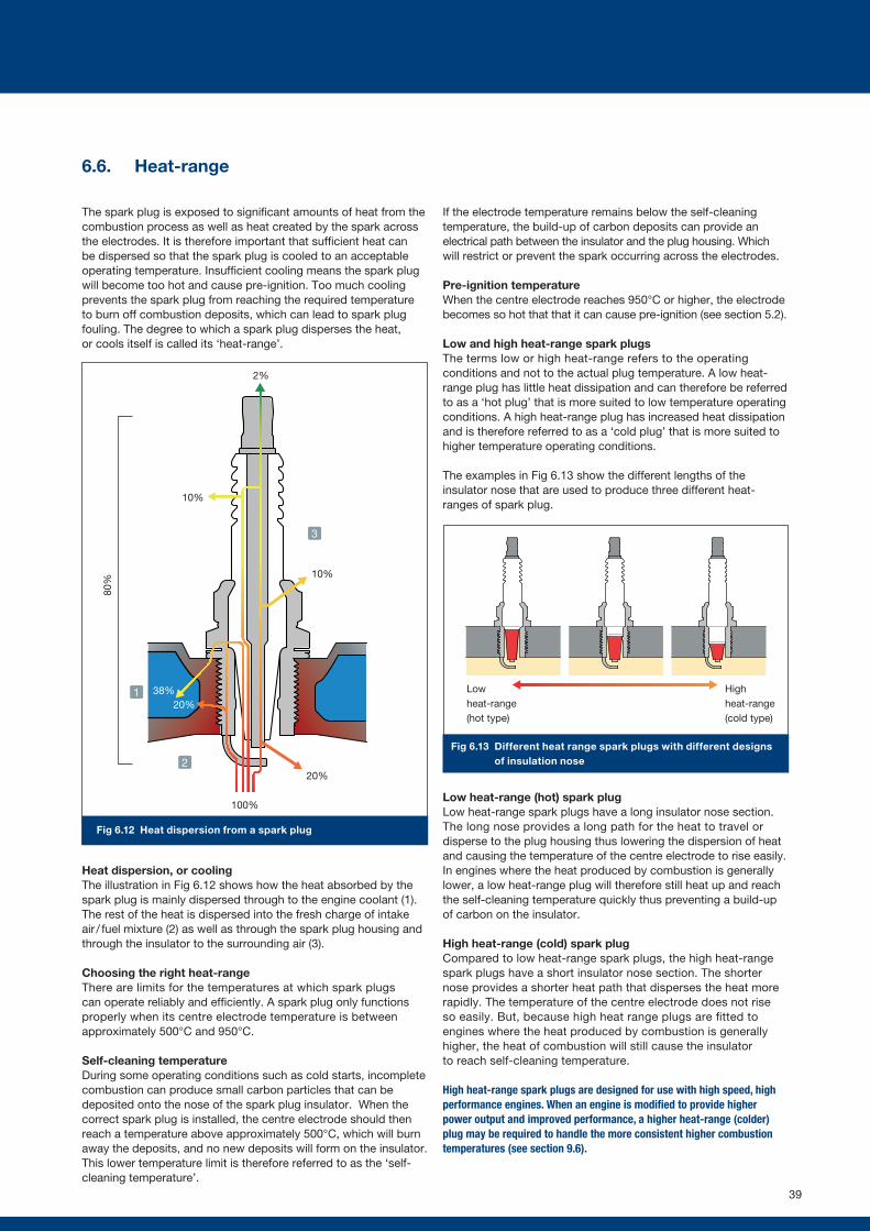
6.6. Heat-range
The spark plug is exposed to significant amounts of heat from the combustion process as well as heat created by the spark across the electrodes. It is therefore important that sufficient heat can be dispersed so that the spark plug is cooled to an acceptable operating temperature. Insufficient cooling means the spark plug will become too hot and cause pre-ignition. Too much cooling prevents the spark plug from reaching the required temperature to burn off combustion deposits, which can lead to spark plug fouling. The degree to which a spark plug disperses the heat, or cools itself is called its ‘heat-range’.
Heat dispersion, or coolingThe illustration in Fig 6.12 shows how the heat absorbed by the spark plug is mainly dispersed through to the engine coolant (1). The rest of the heat is dispersed into the fresh charge of intake air / fuel mixture (2) as well as through the spark plug housing and through the insulator to the surrounding air (3).
Choosing the right heat-rangeThere are limits for the temperatures at which spark plugs can operate reliably and efficiently. A spark plug only functions properly when its centre electrode temperature is between approximately 500°C and 950°C.
Self-cleaning temperature During some operating conditions such as cold starts, incomplete combustion can produce small carbon particles that can be deposited onto the nose of the spark plug insulator. When the correct spark plug is installed, the centre electrode should then reach a temperature above approximately 500°C, which will burn away the deposits, and no new deposits will form on the insulator. This lower temperature limit is therefore referred to as the ‘self-cleaning temperature’.
If the electrode temperature remains below the self-cleaning temperature, the build-up of carbon deposits can provide an electrical path between the insulator and the plug housing. Which will restrict or prevent the spark occurring across the electrodes.
Pre-ignition temperature When the centre electrode reaches 950°C or higher, the electrode becomes so hot that that it can cause pre-ignition (see section 5.2).
Low and high heat-range spark plugsThe terms low or high heat-range refers to the operating conditions and not to the actual plug temperature. A low heat-range plug has little heat dissipation and can therefore be referred to as a ‘hot plug’ that is more suited to low temperature operating conditions. A high heat-range plug has increased heat dissipation and is therefore referred to as a ‘cold plug’ that is more suited to higher temperature operating conditions.
The examples in Fig 6.13 show the different lengths of the insulator nose that are used to produce three different heat-ranges of spark plug.
Low heat-range (hot) spark plug Low heat-range spark plugs have a long insulator nose section. The long nose provides a long path for the heat to travel or disperse to the plug housing thus lowering the dispersion of heat and causing the temperature of the centre electrode to rise easily. In engines where the heat produced by combustion is generally lower, a low heat-range plug will therefore still heat up and reach the self-cleaning temperature quickly thus preventing a build-up of carbon on the insulator.
High heat-range (cold) spark plugCompared to low heat-range spark plugs, the high heat-range spark plugs have a short insulator nose section. The shorter nose provides a shorter heat path that disperses the heat more rapidly. The temperature of the centre electrode does not rise so easily. But, because high heat range plugs are fitted to engines where the heat produced by combustion is generally higher, the heat of combustion will still cause the insulator to reach self-cleaning temperature.
High heat-range spark plugs are designed for use with high speed, high performance engines. When an engine is modified to provide higher power output and improved performance, a higher heat-range (colder) plug may be required to handle the more consistent higher combustion temperatures (see section 9.6).
Fig 6.13 Different heat range spark plugs with different designs of insulation nose
High heat-range (cold type)
Low heat-range (hot type)
1
2
3
Fig 6.12 Heat dispersion from a spark plug
2%
100%
20%
10%
10%
20%38%
80%
39
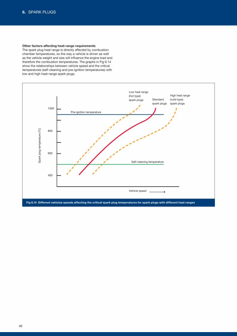
Fig 6.14 Different vehicles speeds affecting the critical spark plug temperatures for spark plugs with different heat ranges
Other factors affecting heat-range requirementsThe spark plug heat range is directly affected by combustion chamber temperatures, so the way a vehicle is driven as well as the vehicle weight and size will influence the engine load and therefore the combustion temperatures. The graphs in Fig 6.14 show the relationships between vehicle speed and the critical temperatures (self-cleaning and pre-ignition temperatures) with low and high heat-range spark plugs.
Sp
ark
plu
g te
mp
erat
ure
(ºC
)
1000
800
600
400
Vehicle speed
Self-cleaning temperature
Pre-ignition temperature
Low heat range (hot type) spark plugs
High heat range (cold type) spark plugs
Standard spark plugs
40
6. SPARK PLUGS

DENSO HIGHLIGHT
DENSO produces a range of spark plugs with different electrode shapes
and sizes that help to reduce the quenching effect for different engine
applications. These different designs of spark plug are shown in chapter 7.
Fig 6.16 Quenching effect created by small and large plug gaps
Fig 6.15 Quenching effect created by different size electrodes
6.7. Flame quenching affecting flame generation and flame growth
Flame generation and growth When the spark is created at the spark plug electrodes, the high temperature of the spark initiates a small flame kernel of burning air / fuel mixture (see section 5.1). The heat of the flame kernel (around 3,000°C) ignites the next layer of air / fuel mixture.
The flame initially grows within the gap between the spark plug electrodes and then expands beyond the spark plug gap to continue as a self-sustaining flame throughout the complete combustion chamber.
The flame front should ideally grow at a consistent and uniform rate so that all of the air / fuel mixture progressively but rapidly combusts. The uniform growth of the flame is dependent on combustion chamber shape, the turbulence and the air / fuel mixture within the combustion chamber.
It is however impossible to create perfectly uniform flame growth because it is not possible to create the perfect shape for a combustion chamber that still contains the valves, the spark plug and, optionally, the injector. Flame growth can be partially disrupted or restricted, and the flame can even be extinguished due to the dispersion of heat away from the flame onto a cold surface.
Turbulence helps expose all the mixture to the flame front, which helps burning all the available air / fuel mixture throughout the combustion chamber.
Flame quenching and electrode temperatureBefore the flame is self-sustaining, when the flame kernel is initially created, it is very close to the electrodes that have a lower temperature than the flame; this lower temperature draws heat away from the flame kernel. The cooling effect can actually cause the flame to extinguish, which is known as the ‘quenching’ effect.
Because cold electrodes will absorb more heat energy from the flame than hot electrodes, the design of the spark plug and electrodes must allow the electrodes to retain sufficient heat to reduce the quenching effect.
The quenching effect can be reduced by the spark plug design; the electrode shape and spark plug gap have a significant effect on the quenching of the flame.
Flame quenching can also occur when the growing flame front is close to the combustion chamber walls. If the engine is cold (such as following a cold start), the low temperature surfaces within the cylinder can (partially) quench the flame (see section 5.3).
Electrode shape. The examples shown in Fig 6.15 illustrate how a larger electrode will draw more heat energy from the flame kernel due to the larger mass and larger surface area. When a smaller centre electrode is used, which has a smaller mass and smaller surface area, it will draw less heat away from the flame kernel thus reducing the potential for flame quenching. A smaller ground electrode will again have the same effect of reducing the flame quenching.
Spark plug gap. With a small electrode gap (Fig 6.16), the electrodes are close to the flame kernel, which makes it easy for the heat to disperse away from the flame to the electrodes; therefore the quenching effect is greater. A bigger spark plug gap has increased space, reducing the interference in the flame generation.
Smaller electrodes with smaller surface area are less likely
to quench the spark
Larger electrodes with larger surface area are more likely to quench the spark
Reduced flame growth
Improved flame growth
Optimal
flame growth
Heat dispersal through the electrodes with a larger plug gap
is more difficult. There is therefore a reduced risk of quenching
Smaller plug gap provides easier heat dispersal.
There is therefore a greater risk of quenching
41
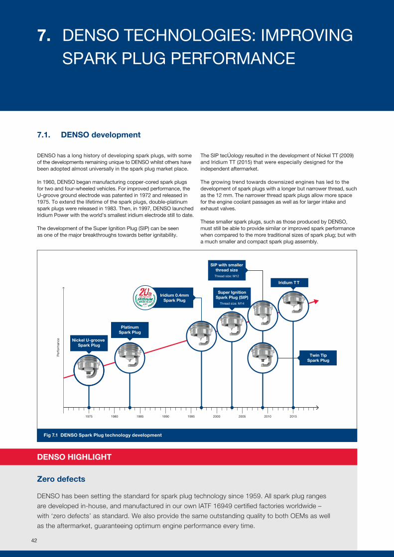
1975 1980 1985 1990 1995 2000 2005 2010 2015
Per
form
ance
PlatinumSpark Plug
Super IgnitionSpark Plug (SIP)
Thread size: M14
SIP with smallerthread size
Thread size: M12
Nickel U-groove Spark Plug
Iridium 0.4mmSpark Plug
Twin TipSpark Plug
Iridium T T
Fig 7.1 DENSO Spark Plug technology development
7.1. DENSO development
DENSO has a long history of developing spark plugs, with some of the developments remaining unique to DENSO whilst others have been adopted almost universally in the spark plug market place.
In 1960, DENSO began manufacturing copper-cored spark plugs for two and four-wheeled vehicles. For improved performance, the U-groove ground electrode was patented in 1972 and released in 1975. To extend the lifetime of the spark plugs, double-platinum spark plugs were released in 1983. Then, in 1997, DENSO launched Iridium Power with the world’s smallest iridium electrode still to date.
The development of the Super Ignition Plug (SIP) can be seen as one of the major breakthroughs towards better ignitability.
The SIP technology resulted in the development of Nickel TT (2009) and Iridium TT (2015) that were especially designed for the independent aftermarket.
The growing trend towards downsized engines has led to the development of spark plugs with a longer but narrower thread, such as the 12 mm. The narrower thread spark plugs allow more space for the engine coolant passages as well as for larger intake and exhaust valves.
These smaller spark plugs, such as those produced by DENSO, must still be able to provide similar or improved spark performance when compared to the more traditional sizes of spark plug; but with a much smaller and compact spark plug assembly.
DENSO HIGHLIGHT
Zero defects
DENSO has been setting the standard for spark plug technology since 1959. All spark plug ranges
are developed in-house, and manufactured in our own IATF 16949 certified factories worldwide –
with ‘zero defects’ as standard. We also provide the same outstanding quality to both OEMs as well
as the aftermarket, guaranteeing optimum engine performance every time.
42
7. DENSO TECHNOLOGIES: IMPROVING SPARK PLUG PERFORMANCE
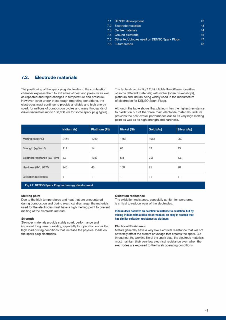
Fig 7.2 DENSO Spark Plug technology development
7.2. Electrode materials
The positioning of the spark plug electrodes in the combustion chamber exposes them to extremes of heat and pressure as well as repeated and rapid changes in temperature and pressure. However, even under these tough operating conditions, the electrodes must continue to provide a reliable and high energy spark for millions of combustion cycles and many thousands of driven kilometres (up to 180,000 km for some spark plug types).
The table shown in Fig 7.2, highlights the different qualities of some different materials; with nickel (often nickel alloys), platinum and iridium being widely used in the manufacture of electrodes for DENSO Spark Plugs.
Although the table shows that platinum has the highest resistance to oxidation out of the three main electrode materials, iridium provides the best overall performance due to its very high melting point as well as its high strength and hardness.
Melting pointDue to the high temperatures and heat that are encountered during combustion and during electrical discharge, the materials used for the electrodes must have a high melting point to prevent melting of the electrode material.
StrengthStronger materials provide stable spark performance and improved long term durability, especially for operation under the high load driving conditions that increase the physical loads on the spark plug electrodes.
Oxidation resistanceThe oxidation resistance, especially at high temperatures, is critical to reduce wear of the electrodes.
Iridium does not have an excellent resistance to oxidation, but by mixing iridium with a little bit of rhodium, an alloy is created that has similar oxidation resistance as platinum.
Electrical ResistanceMetals generally have a very low electrical resistance that will not adversely affect the current or voltage that creates the spark. But throughout the working life of the spark plug, the electrode materials must maintain their very low electrical resistance even when the electrodes are exposed to the harsh operating conditions.
Iridium (Ir) Platinum (Pt) Nickel (Ni) Gold (Au) Silver (Ag)
Melting point (°C) 2454 1769 1453 1063 960
Strength (kgf/mm²) 112 14 68 13 13
Electrical resistance (µΩ ∙ cm) 5.3 10.6 6.8 2.3 1.6
Hardness (HV ; 20°C) 240 40 160 25 26
Oxidation resistance + ++ + ++ ++
43
7.1. DENSO development 42
7.2. Electrode materials 43
7.3. Centre materials 44
7.4. Ground electrode 45
7.5. Other technologies used on DENSO Spark Plugs 47
7.6. Future trends 48
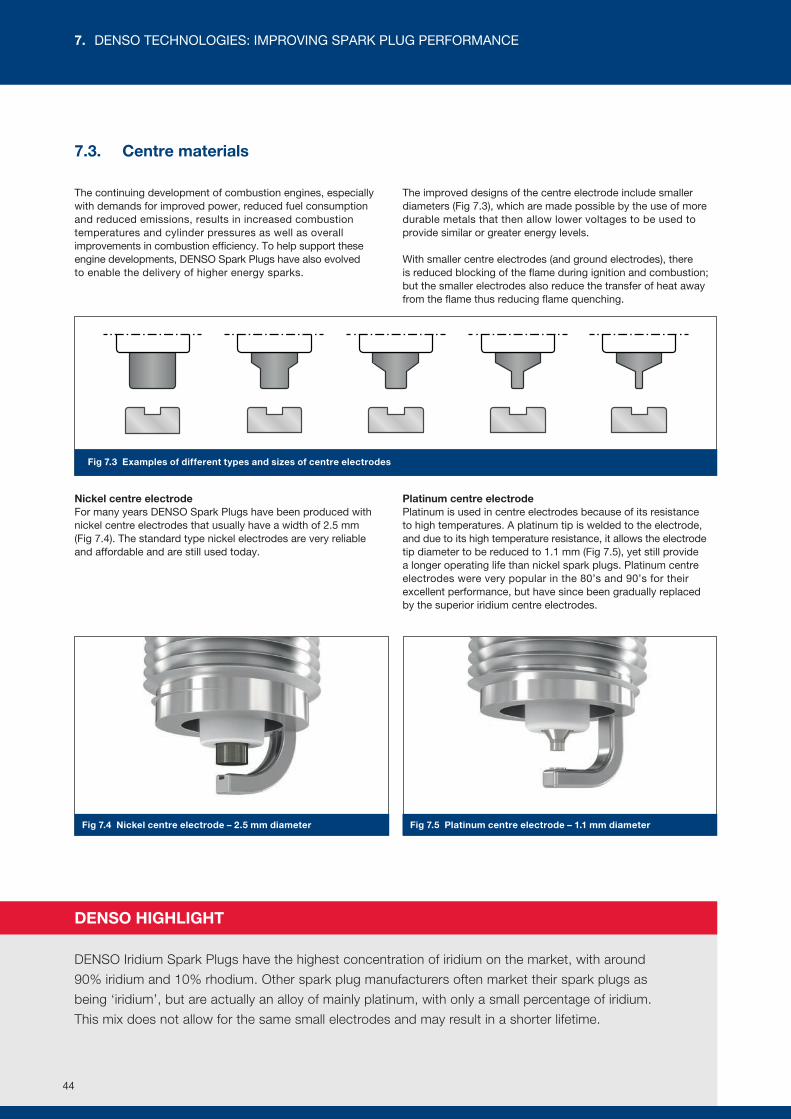
Fig 7.3 Examples of different types and sizes of centre electrodes
Fig 7.4 Nickel centre electrode – 2.5 mm diameter Fig 7.5 Platinum centre electrode – 1.1 mm diameter
7.3. Centre materials
The continuing development of combustion engines, especially with demands for improved power, reduced fuel consumption and reduced emissions, results in increased combustion temperatures and cylinder pressures as well as overall improvements in combustion efficiency. To help support these engine developments, DENSO Spark Plugs have also evolved to enable the delivery of higher energy sparks.
The improved designs of the centre electrode include smaller diameters (Fig 7.3), which are made possible by the use of more durable metals that then allow lower voltages to be used to provide similar or greater energy levels.
With smaller centre electrodes (and ground electrodes), there is reduced blocking of the flame during ignition and combustion; but the smaller electrodes also reduce the transfer of heat away from the flame thus reducing flame quenching.
Nickel centre electrodeFor many years DENSO Spark Plugs have been produced with nickel centre electrodes that usually have a width of 2.5 mm (Fig 7.4). The standard type nickel electrodes are very reliable and affordable and are still used today.
Platinum centre electrode Platinum is used in centre electrodes because of its resistance to high temperatures. A platinum tip is welded to the electrode, and due to its high temperature resistance, it allows the electrode tip diameter to be reduced to 1.1 mm (Fig 7.5), yet still provide a longer operating life than nickel spark plugs. Platinum centre electrodes were very popular in the 80’s and 90’s for their excellent performance, but have since been gradually replaced by the superior iridium centre electrodes.
DENSO HIGHLIGHT
DENSO Iridium Spark Plugs have the highest concentration of iridium on the market, with around
90% iridium and 10% rhodium. Other spark plug manufacturers often market their spark plugs as
being ‘iridium’, but are actually an alloy of mainly platinum, with only a small percentage of iridium.
This mix does not allow for the same small electrodes and may result in a shorter lifetime.
44
7. DENSO TECHNOLOGIES: IMPROVING SPARK PLUG PERFORMANCE
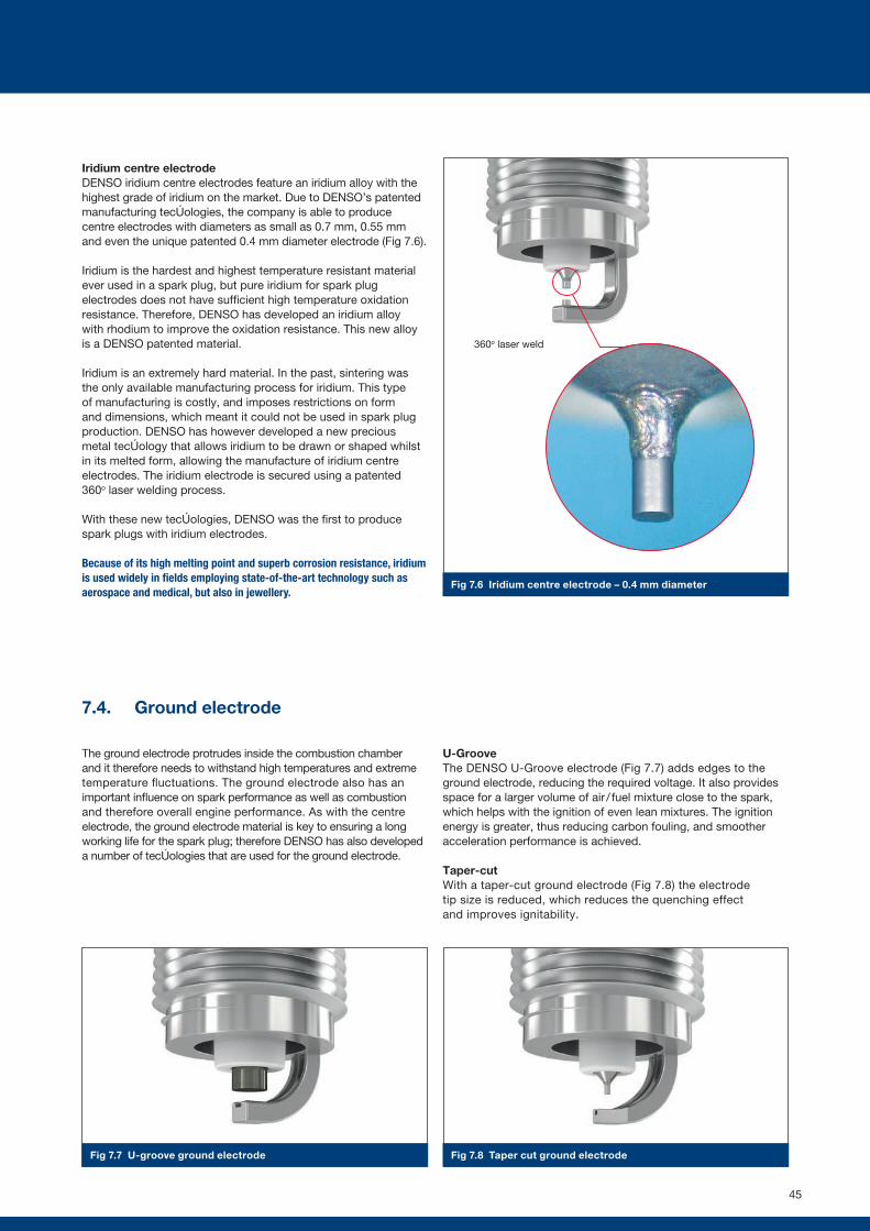
Fig 7.7 U-groove ground electrode Fig 7.8 Taper cut ground electrode
Fig 7.6 Iridium centre electrode – 0.4 mm diameter
Iridium centre electrodeDENSO iridium centre electrodes feature an iridium alloy with the highest grade of iridium on the market. Due to DENSO’s patented manufacturing technologies, the company is able to produce centre electrodes with diameters as small as 0.7 mm, 0.55 mm and even the unique patented 0.4 mm diameter electrode (Fig 7.6).
Iridium is the hardest and highest temperature resistant material ever used in a spark plug, but pure iridium for spark plug electrodes does not have sufficient high temperature oxidation resistance. Therefore, DENSO has developed an iridium alloy with rhodium to improve the oxidation resistance. This new alloy is a DENSO patented material.
Iridium is an extremely hard material. In the past, sintering was the only available manufacturing process for iridium. This type of manufacturing is costly, and imposes restrictions on form and dimensions, which meant it could not be used in spark plug production. DENSO has however developed a new precious metal technology that allows iridium to be drawn or shaped whilst in its melted form, allowing the manufacture of iridium centre electrodes. The iridium electrode is secured using a patented 360o laser welding process.
With these new technologies, DENSO was the first to produce spark plugs with iridium electrodes.
Because of its high melting point and superb corrosion resistance, iridium is used widely in fields employing state-of-the-art technology such as aerospace and medical, but also in jewellery.
7.4. Ground electrode
The ground electrode protrudes inside the combustion chamber and it therefore needs to withstand high temperatures and extreme temperature fluctuations. The ground electrode also has an important influence on spark performance as well as combustion and therefore overall engine performance. As with the centre electrode, the ground electrode material is key to ensuring a long working life for the spark plug; therefore DENSO has also developed a number of technologies that are used for the ground electrode.
U-GrooveThe DENSO U-Groove electrode (Fig 7.7) adds edges to the ground electrode, reducing the required voltage. It also provides space for a larger volume of air / fuel mixture close to the spark, which helps with the ignition of even lean mixtures. The ignition energy is greater, thus reducing carbon fouling, and smoother acceleration performance is achieved.
Taper-cutWith a taper-cut ground electrode (Fig 7.8) the electrode tip size is reduced, which reduces the quenching effect and improves ignitability.
360o laser weld
45
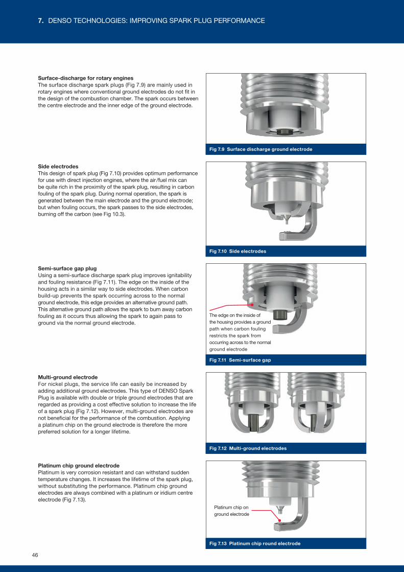
Fig 7.9 Surface discharge ground electrode
Fig 7.10 Side electrodes
Fig 7.11 Semi-surface gap
Fig 7.12 Multi-ground electrodes
Surface-discharge for rotary enginesThe surface discharge spark plugs (Fig 7.9) are mainly used in rotary engines where conventional ground electrodes do not fit in the design of the combustion chamber. The spark occurs between the centre electrode and the inner edge of the ground electrode.
Side electrodesThis design of spark plug (Fig 7.10) provides optimum performance for use with direct injection engines, where the air /fuel mix can be quite rich in the proximity of the spark plug, resulting in carbon fouling of the spark plug. During normal operation, the spark is generated between the main electrode and the ground electrode; but when fouling occurs, the spark passes to the side electrodes, burning off the carbon (see Fig 10.3).
Semi-surface gap plugUsing a semi-surface discharge spark plug improves ignitability and fouling resistance (Fig 7.11). The edge on the inside of the housing acts in a similar way to side electrodes. When carbon build-up prevents the spark occurring across to the normal ground electrode, this edge provides an alternative ground path. This alternative ground path allows the spark to burn away carbon fouling as it occurs thus allowing the spark to again pass to ground via the normal ground electrode.
Multi-ground electrodeFor nickel plugs, the service life can easily be increased by adding additional ground electrodes. This type of DENSO Spark Plug is available with double or triple ground electrodes that are regarded as providing a cost effective solution to increase the life of a spark plug (Fig 7.12). However, multi-ground electrodes are not beneficial for the performance of the combustion. Applying a platinum chip on the ground electrode is therefore the more preferred solution for a longer lifetime.
Platinum chip ground electrodePlatinum is very corrosion resistant and can withstand sudden temperature changes. It increases the lifetime of the spark plug, without substituting the performance. Platinum chip ground electrodes are always combined with a platinum or iridium centre electrode (Fig 7.13).
The edge on the inside of the housing provides a ground path when carbon fouling restricts the spark from occurring across to the normal ground electrode
Fig 7.13 Platinum chip round electrode
Platinum chip on ground electrode
46
7. DENSO TECHNOLOGIES: IMPROVING SPARK PLUG PERFORMANCE
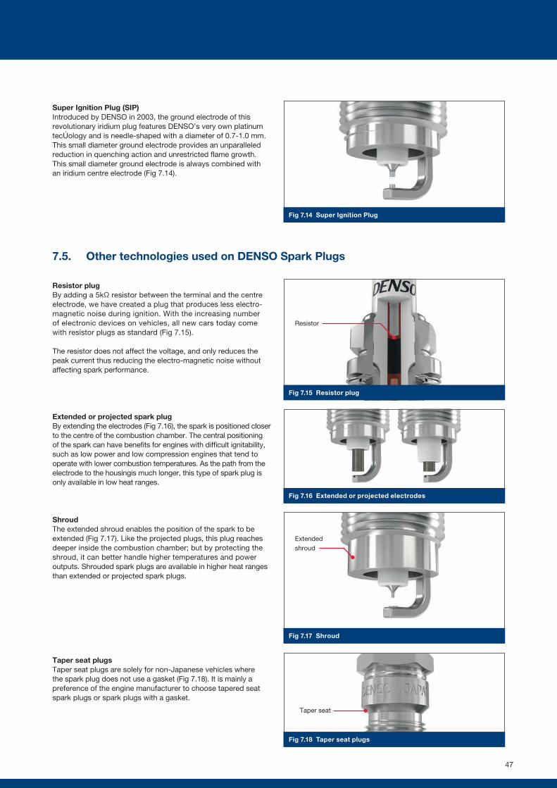
Fig 7.14 Super Ignition Plug
Fig 7.15 Resistor plug
Fig 7.16 Extended or projected electrodes
Fig 7.17 Shroud
Fig 7.18 Taper seat plugs
Super Ignition Plug (SIP)Introduced by DENSO in 2003, the ground electrode of this revolutionary iridium plug features DENSO’s very own platinum technology and is needle-shaped with a diameter of 0.7-1.0 mm. This small diameter ground electrode provides an unparalleled reduction in quenching action and unrestricted flame growth. This small diameter ground electrode is always combined with an iridium centre electrode (Fig 7.14).
7.5. Other technologies used on DENSO Spark Plugs
Resistor plugBy adding a 5kΩ resistor between the terminal and the centre electrode, we have created a plug that produces less electro-magnetic noise during ignition. With the increasing number of electronic devices on vehicles, all new cars today come with resistor plugs as standard (Fig 7.15).
The resistor does not affect the voltage, and only reduces the peak current thus reducing the electro-magnetic noise without affecting spark performance.
Extended or projected spark plugBy extending the electrodes (Fig 7.16), the spark is positioned closer to the centre of the combustion chamber. The central positioning of the spark can have benefits for engines with difficult ignitability, such as low power and low compression engines that tend to operate with lower combustion temperatures. As the path from the electrode to the housingis much longer, this type of spark plug is only available in low heat ranges.
ShroudThe extended shroud enables the position of the spark to be extended (Fig 7.17). Like the projected plugs, this plug reaches deeper inside the combustion chamber; but by protecting the shroud, it can better handle higher temperatures and power outputs. Shrouded spark plugs are available in higher heat ranges than extended or projected spark plugs.
Taper seat plugsTaper seat plugs are solely for non-Japanese vehicles where the spark plug does not use a gasket (Fig 7.18). It is mainly a preference of the engine manufacturer to choose tapered seat spark plugs or spark plugs with a gasket.
Resistor
Extended shroud
Taper seat
47
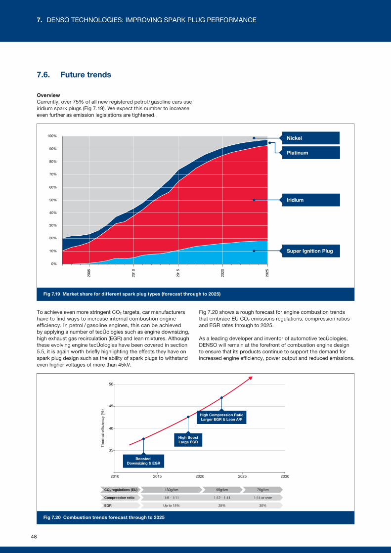
0%
10%
20%
30%
40%
50%
60%
70%
80%
90%
100%
2005
2010
2015
2020
2025
Nickel
Platinum
Iridium
Super Ignition Plug
20152010 2020 2025 2030
Boosted Downsizing & EGR
High BoostLarge EGR
High Compression RatioLarger EGR & Lean A/F
40
35
45
50
Ther
mal
effi
cien
cy (%
)
95g/kmCO2 regulations (EU)
Compression ratio
EGR
75g/km130g/km
1:9 - 1:11 1:12 - 1:14 1:14 or over
Up to 15% 25% 30%
Fig 7.19 Market share for different spark plug types (forecast through to 2025)
Fig 7.20 Combustion trends forecast through to 2025
7.6. Future trends
OverviewCurrently, over 75% of all new registered petrol / gasoline cars use iridium spark plugs (Fig 7.19). We expect this number to increase even further as emission legislations are tightened.
To achieve even more stringent CO2 targets, car manufacturers have to find ways to increase internal combustion engine efficiency. In petrol / gasoline engines, this can be achieved by applying a number of technologies such as engine downsizing, high exhaust gas recirculation (EGR) and lean mixtures. Although these evolving engine technologies have been covered in section 5.5, it is again worth briefly highlighting the effects they have on spark plug design such as the ability of spark plugs to withstand even higher voltages of more than 45kV.
Fig 7.20 shows a rough forecast for engine combustion trends that embrace EU CO2 emissions regulations, compression ratios and EGR rates through to 2025.
As a leading developer and inventor of automotive technologies, DENSO will remain at the forefront of combustion engine design to ensure that its products continue to support the demand for increased engine efficiency, power output and reduced emissions.
48
7. DENSO TECHNOLOGIES: IMPROVING SPARK PLUG PERFORMANCE
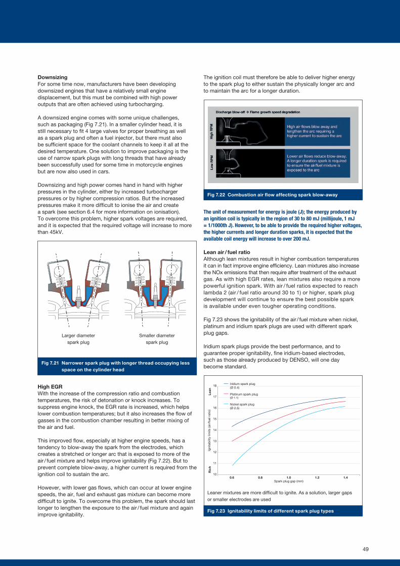
10
11
12
13
14
15
16
17
18
0.6 0.8 1.0 1.2 1.4Spark plug gap (mm)
Igni
tab
ility
lim
its (a
ir/fu
el r
atio
)R
ich
Lean
Iridium spark plug(Ø 0.4)
Platinum spark plug(Ø 1.1)
Nickel spark plug(Ø 2.5)
!"#$%$&%'((&)*'+,%-.'*/%012%31%(&)*."110&+%.'$0&%.01"1%'+4%$5.6&1%'."%'44"4%$&%"+-0+"17%$/"%*."115."%0+%$/"%(&)651$0&+%(/')6".%0+(."'1"18%!/01%."950."1%'%/0-/".%:&;$'-"%$&%(."'$"%'%1*'.<8%=0+".%";"($.&4"1%('+%/";*%."45("%$/"%."950."4%:&;$'-"8
Fig 7.22 Combustion air flow affecting spark blow-away
Fig 7.23 Ignitability limits of different spark plug types
Fig 7.21 Narrower spark plug with longer thread occupying less space on the cylinder head
DownsizingFor some time now, manufacturers have been developing downsized engines that have a relatively small engine displacement, but this must be combined with high power outputs that are often achieved using turbocharging.
A downsized engine comes with some unique challenges, such as packaging (Fig 7.21). In a smaller cylinder head, it is still necessary to fit 4 large valves for proper breathing as well as a spark plug and often a fuel injector, but there must also be sufficient space for the coolant channels to keep it all at the desired temperature. One solution to improve packaging is the use of narrow spark plugs with long threads that have already been successfully used for some time in motorcycle engines but are now also used in cars.
Downsizing and high power comes hand in hand with higher pressures in the cylinder, either by increased turbocharger pressures or by higher compression ratios. But the increased pressures make it more difficult to ionise the air and create a spark (see section 6.4 for more information on ionisation). To overcome this problem, higher spark voltages are required, and it is expected that the required voltage will increase to more than 45kV.
High EGRWith the increase of the compression ratio and combustion temperatures, the risk of detonation or knock increases. To suppress engine knock, the EGR rate is increased, which helps lower combustion temperatures; but it also increases the flow of gasses in the combustion chamber resulting in better mixing of the air and fuel.
This improved flow, especially at higher engine speeds, has a tendency to blow-away the spark from the electrodes, which creates a stretched or longer arc that is exposed to more of the air / fuel mixture and helps improve ignitability (Fig 7.22). But to prevent complete blow-away, a higher current is required from the ignition coil to sustain the arc.
However, with lower gas flows, which can occur at lower engine speeds, the air, fuel and exhaust gas mixture can become more difficult to ignite. To overcome this problem, the spark should last longer to lengthen the exposure to the air / fuel mixture and again improve ignitability.
The ignition coil must therefore be able to deliver higher energy to the spark plug to either sustain the physically longer arc and to maintain the arc for a longer duration.
The unit of measurement for energy is joule (J); the energy produced by an ignition coil is typically in the region of 30 to 80 mJ (millijoule, 1 mJ = 1/1000th J). However, to be able to provide the required higher voltages, the higher currents and longer duration sparks, it is expected that the available coil energy will increase to over 200 mJ.
Lean air / fuel ratioAlthough lean mixtures result in higher combustion temperatures it can in fact improve engine efficiency. Lean mixtures also increase the NOx emissions that then require after treatment of the exhaust gas. As with high EGR rates, lean mixtures also require a more powerful ignition spark. With air / fuel ratios expected to reach lambda 2 (air / fuel ratio around 30 to 1) or higher, spark plug development will continue to ensure the best possible spark is available under even tougher operating conditions.
Fig 7.23 shows the ignitability of the air / fuel mixture when nickel, platinum and iridium spark plugs are used with different spark plug gaps.
Iridium spark plugs provide the best performance, and to guarantee proper ignitability, fine iridium-based electrodes, such as those already produced by DENSO, will one day become standard.
Larger diameter spark plug
Leaner mixtures are more difficult to ignite. As a solution, larger gaps or smaller electrodes are used
Smaller diameter spark plug
49
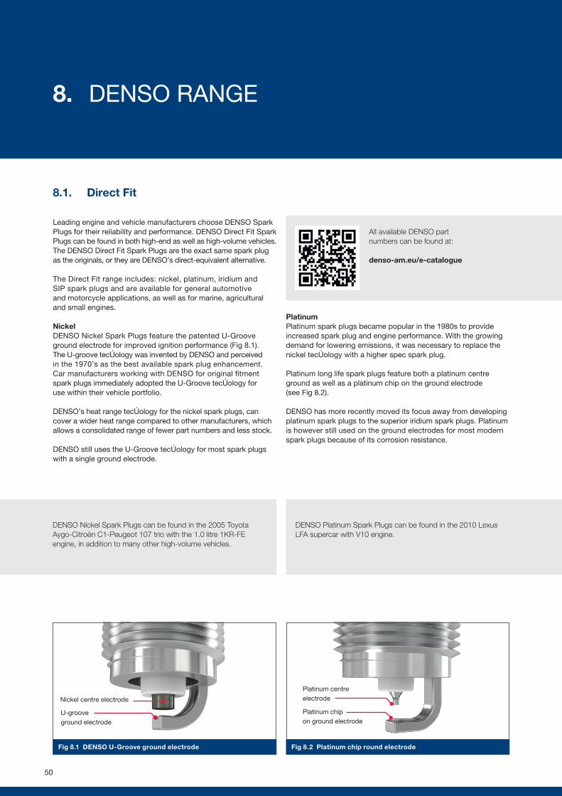
Fig 8.1 DENSO U-Groove ground electrode Fig 8.2 Platinum chip round electrode
8.1. Direct Fit
Leading engine and vehicle manufacturers choose DENSO Spark Plugs for their reliability and performance. DENSO Direct Fit Spark Plugs can be found in both high-end as well as high-volume vehicles. The DENSO Direct Fit Spark Plugs are the exact same spark plug as the originals, or they are DENSO’s direct-equivalent alternative.
The Direct Fit range includes: nickel, platinum, iridium and SIP spark plugs and are available for general automotive and motorcycle applications, as well as for marine, agricultural and small engines.
NickelDENSO Nickel Spark Plugs feature the patented U-Groove ground electrode for improved ignition performance (Fig 8.1). The U-groove technology was invented by DENSO and perceived in the 1970’s as the best available spark plug enhancement. Car manufacturers working with DENSO for original fitment spark plugs immediately adopted the U-Groove technology for use within their vehicle portfolio.
DENSO’s heat range technology for the nickel spark plugs, can cover a wider heat range compared to other manufacturers, which allows a consolidated range of fewer part numbers and less stock.
DENSO still uses the U-Groove technology for most spark plugs with a single ground electrode.
PlatinumPlatinum spark plugs became popular in the 1980s to provide increased spark plug and engine performance. With the growing demand for lowering emissions, it was necessary to replace the nickel technology with a higher spec spark plug.
Platinum long life spark plugs feature both a platinum centre ground as well as a platinum chip on the ground electrode (see Fig 8.2).
DENSO has more recently moved its focus away from developing platinum spark plugs to the superior iridium spark plugs. Platinum is however still used on the ground electrodes for most modern spark plugs because of its corrosion resistance.
Platinum centre electrode
Platinum chip on ground electrode
DENSO Platinum Spark Plugs can be found in the 2010 Lexus LFA supercar with V10 engine.
DENSO Nickel Spark Plugs can be found in the 2005 Toyota Aygo-Citroën C1-Peugeot 107 trio with the 1.0 litre 1KR-FE engine, in addition to many other high-volume vehicles.
Nickel centre electrode
U-groove ground electrode
All available DENSO part numbers can be found at:
denso-am.eu/e-catalogue
50
8. DENSO RANGE
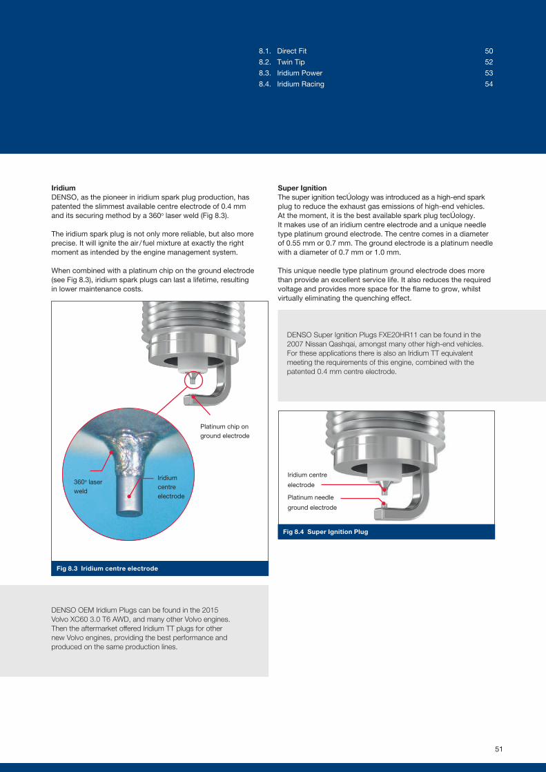
Platinum chip on ground electrode
360o laser weld
Iridium centre electrode
Fig 8.3 Iridium centre electrode
Fig 8.4 Super Ignition Plug
IridiumDENSO, as the pioneer in iridium spark plug production, has patented the slimmest available centre electrode of 0.4 mm and its securing method by a 360o laser weld (Fig 8.3).
The iridium spark plug is not only more reliable, but also more precise. It will ignite the air / fuel mixture at exactly the right moment as intended by the engine management system.
When combined with a platinum chip on the ground electrode (see Fig 8.3), iridium spark plugs can last a lifetime, resulting in lower maintenance costs.
Super IgnitionThe super ignition technology was introduced as a high-end spark plug to reduce the exhaust gas emissions of high-end vehicles. At the moment, it is the best available spark plug technology. It makes use of an iridium centre electrode and a unique needle type platinum ground electrode. The centre comes in a diameter of 0.55 mm or 0.7 mm. The ground electrode is a platinum needle with a diameter of 0.7 mm or 1.0 mm.
This unique needle type platinum ground electrode does more than provide an excellent service life. It also reduces the required voltage and provides more space for the flame to grow, whilst virtually eliminating the quenching effect.
DENSO Super Ignition Plugs FXE20HR11 can be found in the 2007 Nissan Qashqai, amongst many other high-end vehicles. For these applications there is also an Iridium TT equivalent meeting the requirements of this engine, combined with the patented 0.4 mm centre electrode.
DENSO OEM Iridium Plugs can be found in the 2015 Volvo XC60 3.0 T6 AWD, and many other Volvo engines. Then the aftermarket offered Iridium TT plugs for other new Volvo engines, providing the best performance and produced on the same production lines.
Iridium centre
electrode
Platinum needle
ground electrode
51
8.1. Direct Fit 50
8.2. Twin Tip 52
8.3. Iridium Power 53
8.4. Iridium Racing 54
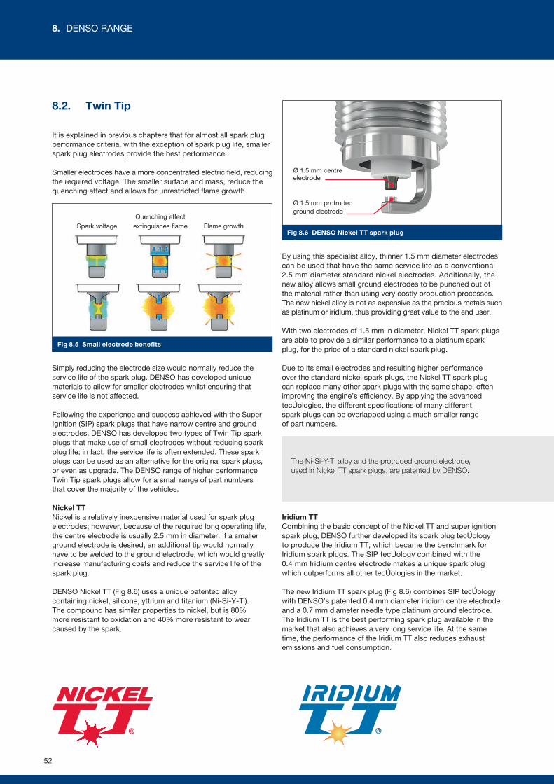
Fig 8.6 DENSO Nickel TT spark plug
Fig 8.5 Small electrode benefits
8.2. Twin Tip
It is explained in previous chapters that for almost all spark plug performance criteria, with the exception of spark plug life, smaller spark plug electrodes provide the best performance.
Smaller electrodes have a more concentrated electric field, reducing the required voltage. The smaller surface and mass, reduce the quenching effect and allows for unrestricted flame growth.
Simply reducing the electrode size would normally reduce the service life of the spark plug. DENSO has developed unique materials to allow for smaller electrodes whilst ensuring that service life is not affected.
Following the experience and success achieved with the Super Ignition (SIP) spark plugs that have narrow centre and ground electrodes, DENSO has developed two types of Twin Tip spark plugs that make use of small electrodes without reducing spark plug life; in fact, the service life is often extended. These spark plugs can be used as an alternative for the original spark plugs, or even as upgrade. The DENSO range of higher performance Twin Tip spark plugs allow for a small range of part numbers that cover the majority of the vehicles.
Nickel TTNickel is a relatively inexpensive material used for spark plug electrodes; however, because of the required long operating life, the centre electrode is usually 2.5 mm in diameter. If a smaller ground electrode is desired, an additional tip would normally have to be welded to the ground electrode, which would greatly increase manufacturing costs and reduce the service life of the spark plug.
DENSO Nickel TT (Fig 8.6) uses a unique patented alloy containing nickel, silicone, yttrium and titanium (Ni-Si-Y-Ti). The compound has similar properties to nickel, but is 80% more resistant to oxidation and 40% more resistant to wear caused by the spark.
By using this specialist alloy, thinner 1.5 mm diameter electrodes can be used that have the same service life as a conventional 2.5 mm diameter standard nickel electrodes. Additionally, the new alloy allows small ground electrodes to be punched out of the material rather than using very costly production processes. The new nickel alloy is not as expensive as the precious metals such as platinum or iridium, thus providing great value to the end user.
With two electrodes of 1.5 mm in diameter, Nickel TT spark plugs are able to provide a similar performance to a platinum spark plug, for the price of a standard nickel spark plug.
Due to its small electrodes and resulting higher performance over the standard nickel spark plugs, the Nickel TT spark plug can replace many other spark plugs with the same shape, often improving the engine’s efficiency. By applying the advanced technologies, the different specifications of many different spark plugs can be overlapped using a much smaller range of part numbers.
Iridium TTCombining the basic concept of the Nickel TT and super ignition spark plug, DENSO further developed its spark plug technology to produce the Iridium TT, which became the benchmark for Iridium spark plugs. The SIP technology combined with the 0.4 mm Iridium centre electrode makes a unique spark plug which outperforms all other technologies in the market.
The new Iridium TT spark plug (Fig 8.6) combines SIP technology with DENSO’s patented 0.4 mm diameter iridium centre electrode and a 0.7 mm diameter needle type platinum ground electrode. The Iridium TT is the best performing spark plug available in the market that also achieves a very long service life. At the same time, the performance of the Iridium TT also reduces exhaust emissions and fuel consumption.
The Ni-Si-Y-Ti alloy and the protruded ground electrode, used in Nickel TT spark plugs, are patented by DENSO.
Ø 1.5 mm centre electrode
Ø 1.5 mm protrudedground electrode
Spark voltage Flame growthQuenching effect
extinguishes flame
52
8. DENSO RANGE
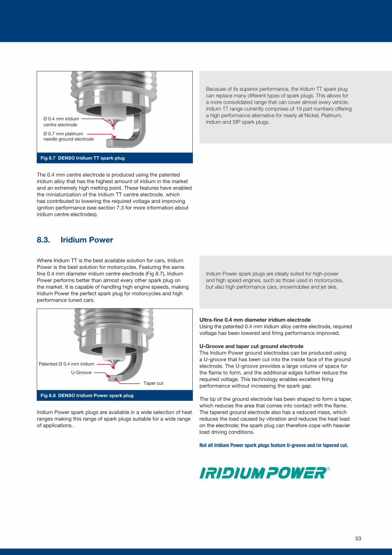
Fig 8.7 DENSO Iridium TT spark plug
Fig 8.8 DENSO Iridium Power spark plug
The 0.4 mm centre electrode is produced using the patented iridium alloy that has the highest amount of iridium in the market and an extremely high melting point. These features have enabled the miniaturization of the Iridium TT centre electrode, which has contributed to lowering the required voltage and improving ignition performance (see section 7.3 for more information about iridium centre electrodes).
8.3. Iridium Power
Where Iridium TT is the best available solution for cars, Iridium Power is the best solution for motorcycles. Featuring the same fine 0.4 mm diameter iridium centre electrode (Fig 8.7), Iridium Power performs better than almost every other spark plug on the market. It is capable of handling high engine speeds, making Iridium Power the perfect spark plug for motorcycles and high performance tuned cars.
Iridium Power spark plugs are available in a wide selection of heat ranges making this range of spark plugs suitable for a wide range of applications.
Ultra-fine 0.4 mm diameter iridium electrodeUsing the patented 0.4 mm iridium alloy centre electrode, required voltage has been lowered and firing performance improved.
U-Groove and taper cut ground electrodeThe Iridium Power ground electrodes can be produced using a U-groove that has been cut into the inside face of the ground electrode. The U-groove provides a large volume of space for the flame to form, and the additional edges further reduce the required voltage. This technology enables excellent firing performance without increasing the spark gap.
The tip of the ground electrode has been shaped to form a taper, which reduces the area that comes into contact with the flame. The tapered ground electrode also has a reduced mass, which reduces the load caused by vibration and reduces the heat load on the electrode; the spark plug can therefore cope with heavier load driving conditions.
Not all Iridium Power spark plugs feature U-groove and /or tapered cut.
Because of its superior performance, the Iridium TT spark plug can replace many different types of spark plugs. This allows for a more consolidated range that can cover almost every vehicle. Iridium TT range currently comprises of 19 part numbers offering a high performance alternative for nearly all Nickel, Platinum, Iridium and SIP spark plugs.
Iridium Power spark plugs are ideally suited for high-power and high speed engines, such as those used in motorcycles, but also high performance cars, snowmobiles and jet skis.
Patented Ø 0.4 mm iridium
U-Groove
Taper cut
Ø 0.4 mm iridium centre electrode
Ø 0.7 mm platinum needle ground electrode
53
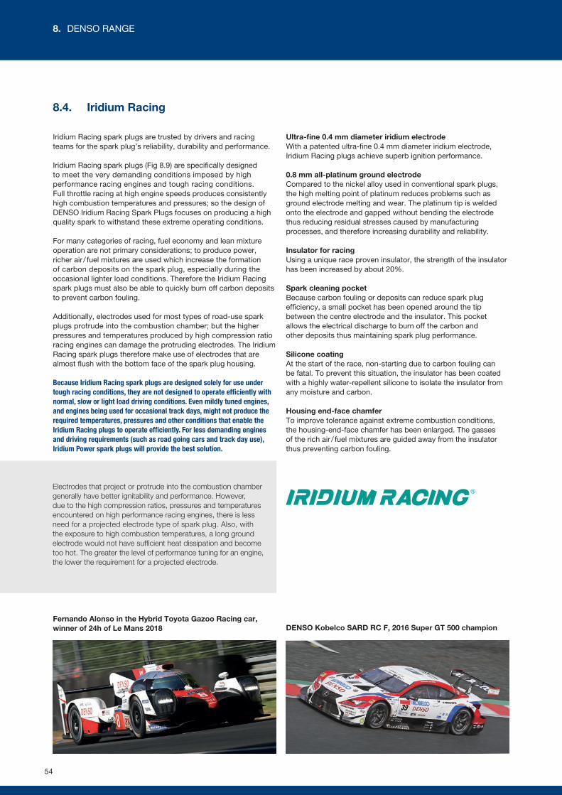
8.4. Iridium Racing
Iridium Racing spark plugs are trusted by drivers and racing teams for the spark plug’s reliability, durability and performance.
Iridium Racing spark plugs (Fig 8.9) are specifically designed to meet the very demanding conditions imposed by high performance racing engines and tough racing conditions. Full throttle racing at high engine speeds produces consistently high combustion temperatures and pressures; so the design of DENSO Iridium Racing Spark Plugs focuses on producing a high quality spark to withstand these extreme operating conditions.
For many categories of racing, fuel economy and lean mixture operation are not primary considerations; to produce power, richer air / fuel mixtures are used which increase the formation of carbon deposits on the spark plug, especially during the occasional lighter load conditions. Therefore the Iridium Racing spark plugs must also be able to quickly burn off carbon deposits to prevent carbon fouling.
Additionally, electrodes used for most types of road-use spark plugs protrude into the combustion chamber; but the higher pressures and temperatures produced by high compression ratio racing engines can damage the protruding electrodes. The Iridium Racing spark plugs therefore make use of electrodes that are almost flush with the bottom face of the spark plug housing.
Because Iridium Racing spark plugs are designed solely for use under tough racing conditions, they are not designed to operate efficiently with normal, slow or light load driving conditions. Even mildly tuned engines, and engines being used for occasional track days, might not produce the required temperatures, pressures and other conditions that enable the Iridium Racing plugs to operate efficiently. For less demanding engines and driving requirements (such as road going cars and track day use), Iridium Power spark plugs will provide the best solution.
Ultra-fine 0.4 mm diameter iridium electrodeWith a patented ultra-fine 0.4 mm diameter iridium electrode, Iridium Racing plugs achieve superb ignition performance.
0.8 mm all-platinum ground electrodeCompared to the nickel alloy used in conventional spark plugs, the high melting point of platinum reduces problems such as ground electrode melting and wear. The platinum tip is welded onto the electrode and gapped without bending the electrode thus reducing residual stresses caused by manufacturing processes, and therefore increasing durability and reliability.
Insulator for racingUsing a unique race proven insulator, the strength of the insulator has been increased by about 20%.
Spark cleaning pocketBecause carbon fouling or deposits can reduce spark plug efficiency, a small pocket has been opened around the tip between the centre electrode and the insulator. This pocket allows the electrical discharge to burn off the carbon and other deposits thus maintaining spark plug performance.
Silicone coatingAt the start of the race, non-starting due to carbon fouling can be fatal. To prevent this situation, the insulator has been coated with a highly water-repellent silicone to isolate the insulator from any moisture and carbon.
Housing end-face chamferTo improve tolerance against extreme combustion conditions, the housing-end-face chamfer has been enlarged. The gasses of the rich air / fuel mixtures are guided away from the insulator thus preventing carbon fouling.
Electrodes that project or protrude into the combustion chamber generally have better ignitability and performance. However, due to the high compression ratios, pressures and temperatures encountered on high performance racing engines, there is less need for a projected electrode type of spark plug. Also, with the exposure to high combustion temperatures, a long ground electrode would not have sufficient heat dissipation and become too hot. The greater the level of performance tuning for an engine, the lower the requirement for a projected electrode.
Fernando Alonso in the Hybrid Toyota Gazoo Racing car, winner of 24h of Le Mans 2018 DENSO Kobelco SARD RC F, 2016 Super GT 500 champion
54
8. DENSO RANGE
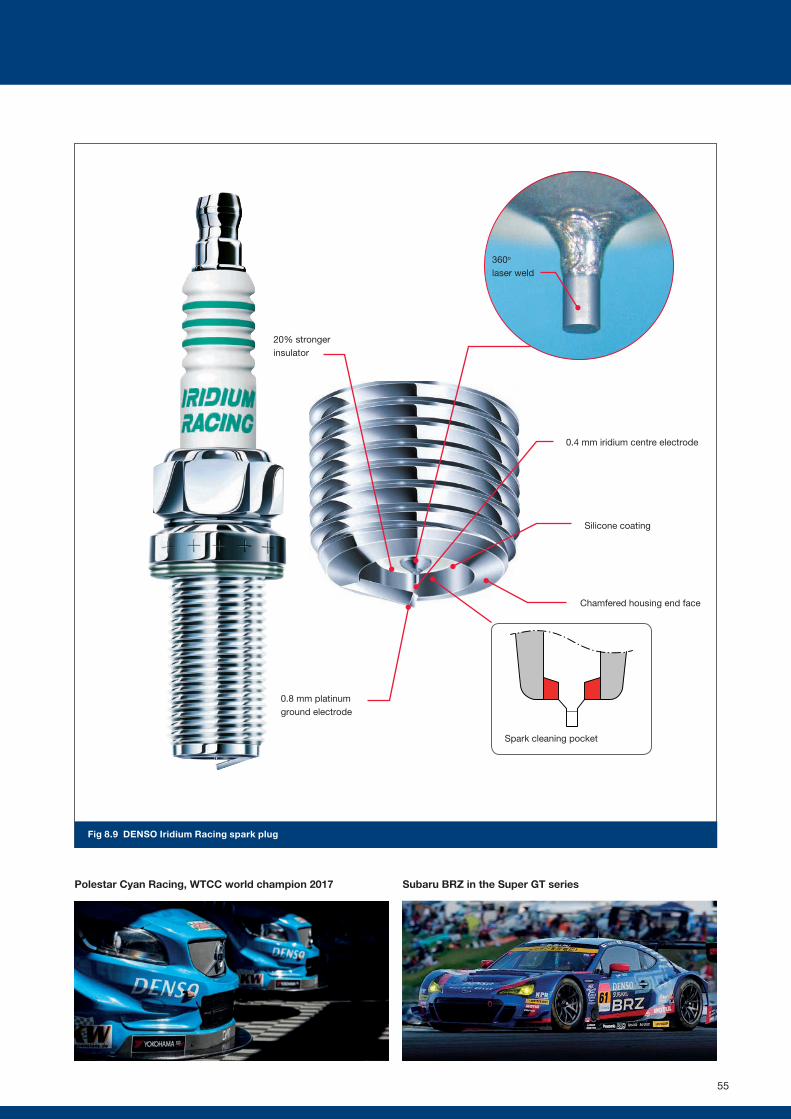
0.8 mm platinum ground electrode
Silicone coating
0.4 mm iridium centre electrode
20% stronger insulator
Chamfered housing end face
Spark cleaning pocket
360o
laser weld
Polestar Cyan Racing, WTCC world champion 2017 Subaru BRZ in the Super GT series
Fig 8.9 DENSO Iridium Racing spark plug
55

9.1. Why upgrade your spark plug?
There are many reasons for upgrading from a standard spark plug to a higher performance spark plug that provides improved ignition performance. You might be seeking the maximum possible engine power for racing, you might simply want to improve fuel economy for normal daily driving, or you might want to solve a difficult starting or idling engine. But whatever the reasons for upgrading, the DENSO Spark Plug range provides a suitable upgrade for almost all vehicles.
The DENSO e-catalogue lists standard and upgrade specification spark plugs for most vehicles including motorcycles. The e-catalogue can be accessed at: denso-am.eu/e-catalogue
The main benefits of upgradingThe main benefits gained by upgrading spark plugs are listed in the following sections; but as well as improvements in engine power and torque, there can be noticeable improvements in engine smoothness, starting, cold running and fuel economy along with the hidden benefits of reduced emissions. Additionally, upgrading to a higher specification spark plug can help to overcome occasional or even persistent misfires at idle speed or under load.
For those vehicles using standard specification nickel spark plugs, upgrading to iridium plugs provides better ignition performance, which is usually achieved with lower voltages. The lower initial voltage requirement places less stress on the ignition coil and more energy remains in the coil, which enables the ignition system to perform better under more demanding operating conditions such as full load acceleration.
LPG /CNGFor vehicles that have been converted to run on LPG or CNG, the benefits of upgrading can be even more noticeable due to the increased difficulties of igniting gas fuels, which requires a higher ignition voltage (see section 9.5). Combustion temperatures for LPG/CNG also fluctuate more than with petrol/gasoline engines thus contributing to a reduced service life of up to 30%. By upgrading nickel spark plugs to longer life iridium spark plugs with improved ignition performance, engine performance is improved and spark plug replacement intervals are extended.
The benefits of modern spark plug technologyOne important factor to consider is the improvement in spark plug technology in recent years. Many newer vehicles have originally been fitted as standard with iridium spark plugs that are more efficient compared to earlier spark plug designs. Although replacement spark plugs of the same specification might be available, it will be beneficial to fit a more modern design higher specification replacement spark plug (such as the DENSO Iridium TT) that improves ignition and engine performance.
The benefit of upgrading strongly depends on the standard type of spark plug. When upgrading from a nickel to an iridium spark plug, a noticeable difference can be measured. However, when upgrading from iridium to an SIP spark plug (such as DENSO Iridium TT), the difference will be smaller.
To find the best Iridium spark plug for your LPG or CNG application, check the DENSO e-catalogue.
denso-am.eu/e-catalogue
56
9. UPGRADE YOUR SPARK PLUGS
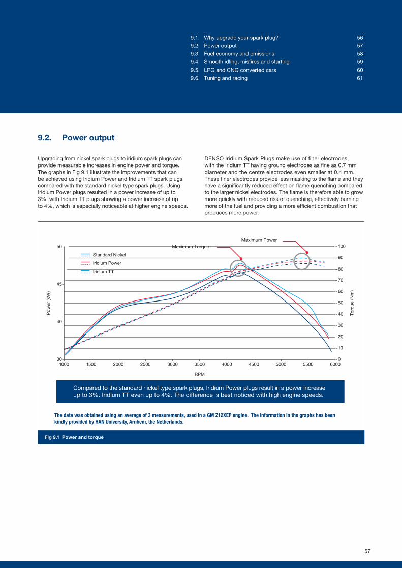
9.2. Power output
Upgrading from nickel spark plugs to iridium spark plugs can provide measurable increases in engine power and torque. The graphs in Fig 9.1 illustrate the improvements that can be achieved using Iridium Power and Iridium TT spark plugs compared with the standard nickel type spark plugs. Using Iridium Power plugs resulted in a power increase of up to 3%, with Iridium TT plugs showing a power increase of up to 4%, which is especially noticeable at higher engine speeds.
DENSO Iridium Spark Plugs make use of finer electrodes, with the Iridium TT having ground electrodes as fine as 0.7 mm diameter and the centre electrodes even smaller at 0.4 mm. These finer electrodes provide less masking to the flame and they have a significantly reduced effect on flame quenching compared to the larger nickel electrodes. The flame is therefore able to grow more quickly with reduced risk of quenching, effectively burning more of the fuel and providing a more efficient combustion that produces more power.
30
40
45
50
1000 1500 2000 2500 3000 3500 4000 4500 5000 5500 6000
RPM
Pow
er (k
W)
Standard Nickel
Iridium Power
Iridium TT
Compared to the standard nickel type spark plugs, Iridium Power plugs result in a power increase up to 3%. Iridium TT even up to 4%. The difference is best noticed with high engine speeds.
0
10
20
30
40
50
60
70
80
90
100
Torq
ue (N
m)
Fig 9.1 Power and torque
The data was obtained using an average of 3 measurements, used in a GM Z12XEP engine. The information in the graphs has been kindly provided by HAN University, Arnhem, the Netherlands.
Maximum TorqueMaximum Power
57
9.1. Why upgrade your spark plug? 56
9.2. Power output 57
9.3. Fuel economy and emissions 58
9.4. Smooth idling, misfires and starting 59
9.5. LPG and CNG converted cars 60
9.6. Tuning and racing 61
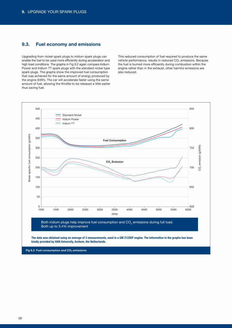
9.3. Fuel economy and emissions
Upgrading from nickel spark plugs to iridium spark plugs can enable the fuel to be used more efficiently during acceleration and high load conditions. The graphs in Fig 9.2 again compare Iridium Power and Iridium TT spark plugs with the standard nickel type spark plugs. The graphs show the improved fuel consumption that was achieved for the same amount of energy produced by the engine (kWh). The car will accelerate faster using the same amount of fuel, allowing the throttle to be released a little earlier thus saving fuel.
This reduced consumption of fuel required to produce the same vehicle performance, results in reduced CO2 emissions. Because the fuel is burned more efficiently during combustion within the engine rather than in the exhaust, other harmful emissions are also reduced.
0
50
100
150
200
250
300
350
400
450
500
600
650
700
750
800
850
1000 1500 2000 2500 3000 3500 4000 4500 5000 5500
Bre
ak s
pec
ific
fuel
con
sum
ptio
n (g
/kW
h)
6000
CO
2 em
issi
on (g
/kW
h)
RPM
Fuel Consumption
CO2 Emission
Both iridium plugs help improve fuel consumption and CO2 emissions during full load.Both up to 3.4% improvement
Standard Nickel
Iridium Power
Iridium TT
Fig 9.2 Fuel consumption and CO2 emissions
The data was obtained using an average of 3 measurements, used in a GM Z12XEP engine. The information in the graphs has been kindly provided by HAN University, Arnhem, the Netherlands.
58
9. UPGRADE YOUR SPARK PLUGS
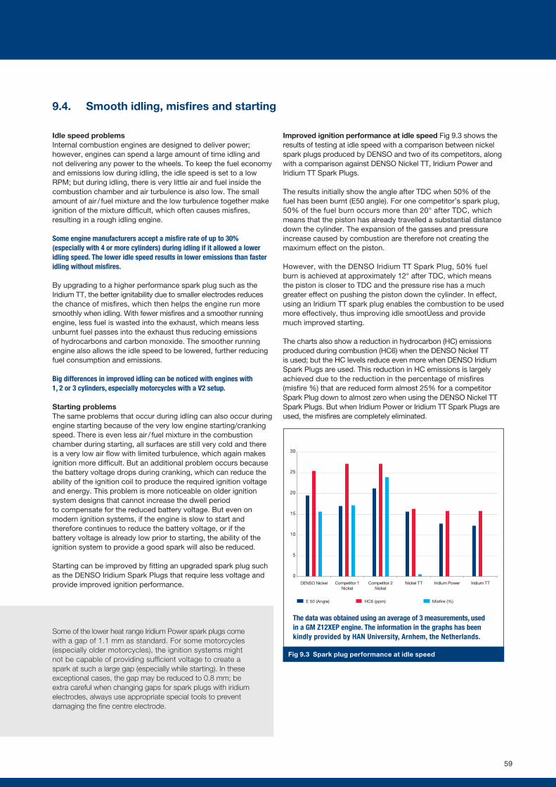
25
30
DENSO Nickel Competitor 1 Nickel
Competitor 2 Nickel
Nickel TT Iridium Power Iridium TT
20
15
10
5
0
HC6 (ppm)E 50 (Angle) Misfire (%)
Fig 9.3 Spark plug performance at idle speed
9.4. Smooth idling, misfires and starting
Idle speed problemsInternal combustion engines are designed to deliver power; however, engines can spend a large amount of time idling and not delivering any power to the wheels. To keep the fuel economy and emissions low during idling, the idle speed is set to a low RPM; but during idling, there is very little air and fuel inside the combustion chamber and air turbulence is also low. The small amount of air / fuel mixture and the low turbulence together make ignition of the mixture difficult, which often causes misfires, resulting in a rough idling engine.
Some engine manufacturers accept a misfire rate of up to 30% (especially with 4 or more cylinders) during idling if it allowed a lower idling speed. The lower idle speed results in lower emissions than faster idling without misfires.
By upgrading to a higher performance spark plug such as the Iridium TT, the better ignitability due to smaller electrodes reduces the chance of misfires, which then helps the engine run more smoothly when idling. With fewer misfires and a smoother running engine, less fuel is wasted into the exhaust, which means less unburnt fuel passes into the exhaust thus reducing emissions of hydrocarbons and carbon monoxide. The smoother running engine also allows the idle speed to be lowered, further reducing fuel consumption and emissions.
Big differences in improved idling can be noticed with engines with 1, 2 or 3 cylinders, especially motorcycles with a V2 setup.
Starting problemsThe same problems that occur during idling can also occur during engine starting because of the very low engine starting/cranking speed. There is even less air / fuel mixture in the combustion chamber during starting, all surfaces are still very cold and there is a very low air flow with limited turbulence, which again makes ignition more difficult. But an additional problem occurs because the battery voltage drops during cranking, which can reduce the ability of the ignition coil to produce the required ignition voltage and energy. This problem is more noticeable on older ignition system designs that cannot increase the dwell period to compensate for the reduced battery voltage. But even on modern ignition systems, if the engine is slow to start and therefore continues to reduce the battery voltage, or if the battery voltage is already low prior to starting, the ability of the ignition system to provide a good spark will also be reduced.
Starting can be improved by fitting an upgraded spark plug such as the DENSO Iridium Spark Plugs that require less voltage and provide improved ignition performance.
Improved ignition performance at idle speed Fig 9.3 shows the results of testing at idle speed with a comparison between nickel spark plugs produced by DENSO and two of its competitors, along with a comparison against DENSO Nickel TT, Iridium Power and Iridium TT Spark Plugs.
The results initially show the angle after TDC when 50% of the fuel has been burnt (E50 angle). For one competitor’s spark plug, 50% of the fuel burn occurs more than 20° after TDC, which means that the piston has already travelled a substantial distance down the cylinder. The expansion of the gasses and pressure increase caused by combustion are therefore not creating the maximum effect on the piston.
However, with the DENSO Iridium TT Spark Plug, 50% fuel burn is achieved at approximately 12° after TDC, which means the piston is closer to TDC and the pressure rise has a much greater effect on pushing the piston down the cylinder. In effect, using an Iridium TT spark plug enables the combustion to be used more effectively, thus improving idle smoothness and provide much improved starting.
The charts also show a reduction in hydrocarbon (HC) emissions produced during combustion (HC6) when the DENSO Nickel TT is used; but the HC levels reduce even more when DENSO Iridium Spark Plugs are used. This reduction in HC emissions is largely achieved due to the reduction in the percentage of misfires (misfire %) that are reduced form almost 25% for a competitor Spark Plug down to almost zero when using the DENSO Nickel TT Spark Plugs. But when Iridium Power or Iridium TT Spark Plugs are used, the misfires are completely eliminated.
Some of the lower heat range Iridium Power spark plugs come with a gap of 1.1 mm as standard. For some motorcycles (especially older motorcycles), the ignition systems might not be capable of providing sufficient voltage to create a spark at such a large gap (especially while starting). In these exceptional cases, the gap may be reduced to 0.8 mm; be extra careful when changing gaps for spark plugs with iridium electrodes, always use appropriate special tools to prevent damaging the fine centre electrode.
The data was obtained using an average of 3 measurements, used in a GM Z12XEP engine. The information in the graphs has been kindly provided by HAN University, Arnhem, the Netherlands.
59
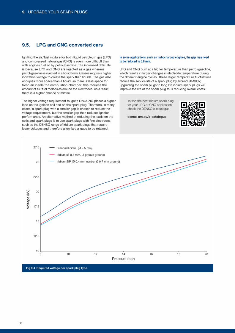
9.5. LPG and CNG converted cars
Igniting the air / fuel mixture for both liquid petroleum gas (LPG) and compressed natural gas (CNG) is even more difficult than with engines fuelled by petrol/gasoline. The increased difficulty is because LPG and CNG are injected as a gas whereas petrol /gasoline is injected in a liquid form. Gasses require a higher ionization voltage to create the spark than liquids. The gas also occupies more space than a liquid, so there is less space for fresh air inside the combustion chamber; this reduces the amount of air / fuel molecules around the electrodes. As a result, there is a higher chance of misfire.
The higher voltage requirement to ignite LPG/CNG places a higher load on the ignition coil and on the spark plug. Therefore, in many cases, a spark plug with a smaller gap is chosen to reduce the voltage requirement, but the smaller gap then reduces ignition performance. An alternative method of reducing the loads on the coils and spark plugs is to use spark plugs with fine electrodes such as the DENSO range of iridium spark plugs that require lower voltages and therefore allow larger gaps to be retained.
In some applications, such as turbocharged engines, the gap may need to be reduced to 0.8 mm.
LPG and CNG burn at a higher temperature than petrol/gasoline, which results in larger changes in electrode temperature during the different engine cycles. These larger temperature fluctuations reduce the service life of a spark plug by around 20-30%; upgrading the spark plugs to long life iridium spark plugs will improve the life of the spark plug thus reducing overall costs.
To find the best Iridium spark plug for your LPG or CNG application, check the DENSO e-catalogue.
denso-am.eu/e-catalogue
10
12.5
15
17.5
20
22.5
25
27.5
8 10 12 14
Pressure (bar)
Vol
tage
(kV
)
16 18 20
Standard nickel (Ø 2.5 mm)
Iridium (Ø 0.4 mm, U-groove ground)
Iridium SIP (Ø 0.4 mm centre, Ø 0.7 mm ground)
Fig 9.4 Required voltage per spark plug type
60
9. UPGRADE YOUR SPARK PLUGS
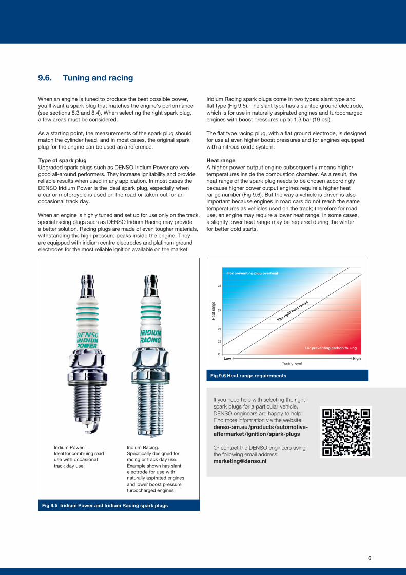
9.6. Tuning and racing
When an engine is tuned to produce the best possible power, you’ll want a spark plug that matches the engine’s performance (see sections 8.3 and 8.4). When selecting the right spark plug, a few areas must be considered.
As a starting point, the measurements of the spark plug should match the cylinder head, and in most cases, the original spark plug for the engine can be used as a reference.
Type of spark plugUpgraded spark plugs such as DENSO Iridium Power are very good all-around performers. They increase ignitability and provide reliable results when used in any application. In most cases the DENSO Iridium Power is the ideal spark plug, especially when a car or motorcycle is used on the road or taken out for an occasional track day.
When an engine is highly tuned and set up for use only on the track, special racing plugs such as DENSO Iridium Racing may provide a better solution. Racing plugs are made of even tougher materials, withstanding the high pressure peaks inside the engine. They are equipped with iridium centre electrodes and platinum ground electrodes for the most reliable ignition available on the market.
Iridium Racing spark plugs come in two types: slant type and flat type (Fig 9.5). The slant type has a slanted ground electrode, which is for use in naturally aspirated engines and turbocharged engines with boost pressures up to 1.3 bar (19 psi).
The flat type racing plug, with a flat ground electrode, is designed for use at even higher boost pressures and for engines equipped with a nitrous oxide system.
Heat rangeA higher power output engine subsequently means higher temperatures inside the combustion chamber. As a result, the heat range of the spark plug needs to be chosen accordingly because higher power output engines require a higher heat range number (Fig 9.6). But the way a vehicle is driven is also important because engines in road cars do not reach the same temperatures as vehicles used on the track; therefore for road use, an engine may require a lower heat range. In some cases, a slightly lower heat range may be required during the winter for better cold starts.
If you need help with selecting the right spark plugs for a particular vehicle, DENSO engineers are happy to help. Find more information via the website: denso-am.eu /products /automotive-aftermarket /ignition /spark-plugs
Or contact the DENSO engineers using the following email address: [email protected]
20
22
24
27
31
Tuning levelLow High
Hea
t ra
nge
The right h
eat range
The right h
eat range
For preventing carbon fouling
For preventing plug overheat
Fig 9.5 Iridium Power and Iridium Racing spark plugs
Fig 9.6 Heat range requirements
Iridium Racing.Specifically designed for racing or track day use. Example shown has slant electrode for use with naturally aspirated engines and lower boost pressure turbocharged engines
Iridium Power.Ideal for combining road use with occasional track day use
61
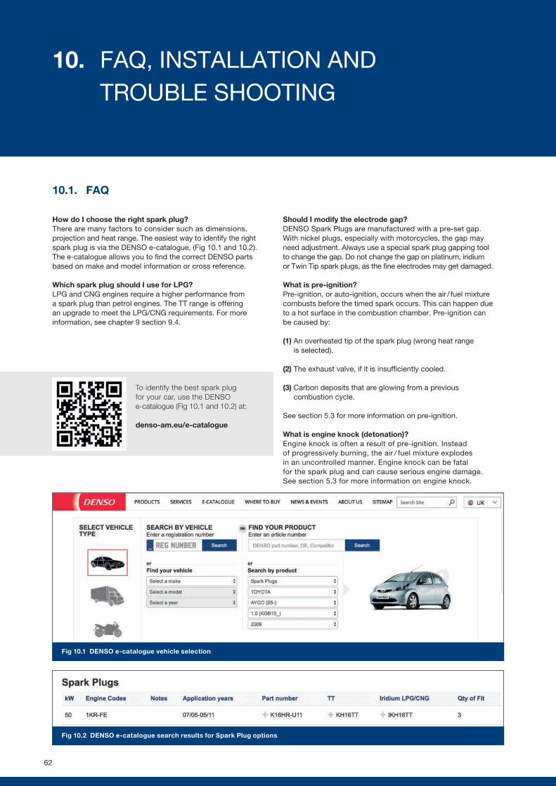
To identify the best spark plug for your car, use the DENSO e-catalogue (Fig 10.1 and 10.2) at:
denso-am.eu/e-catalogue
Fig 10.1 DENSO e-catalogue vehicle selection
Fig 10.2 DENSO e-catalogue search results for Spark Plug options
10.1. FAQ
How do I choose the right spark plug?There are many factors to consider such as dimensions, projection and heat range. The easiest way to identify the right spark plug is via the DENSO e-catalogue, (Fig 10.1 and 10.2). The e-catalogue allows you to find the correct DENSO parts based on make and model information or cross reference.
Which spark plug should I use for LPG?LPG and CNG engines require a higher performance from a spark plug than petrol engines. The TT range is offering an upgrade to meet the LPG/CNG requirements. For more information, see chapter 9 section 9.4.
Should I modify the electrode gap?DENSO Spark Plugs are manufactured with a pre-set gap. With nickel plugs, especially with motorcycles, the gap may need adjustment. Always use a special spark plug gapping tool to change the gap. Do not change the gap on platinum, iridium or Twin Tip spark plugs, as the fine electrodes may get damaged.
What is pre-ignition?Pre-ignition, or auto-ignition, occurs when the air / fuel mixture combusts before the timed spark occurs. This can happen due to a hot surface in the combustion chamber. Pre-ignition can be caused by:
(1) An overheated tip of the spark plug (wrong heat range is selected).
(2) The exhaust valve, if it is insufficiently cooled.
(3) Carbon deposits that are glowing from a previous combustion cycle.
See section 5.3 for more information on pre-ignition.
What is engine knock (detonation)?Engine knock is often a result of pre-ignition. Instead of progressively burning, the air / fuel mixture explodes in an uncontrolled manner. Engine knock can be fatal for the spark plug and can cause serious engine damage. See section 5.3 for more information on engine knock.
62
10. FAQ, INSTALLATION AND TROUBLE SHOOTING
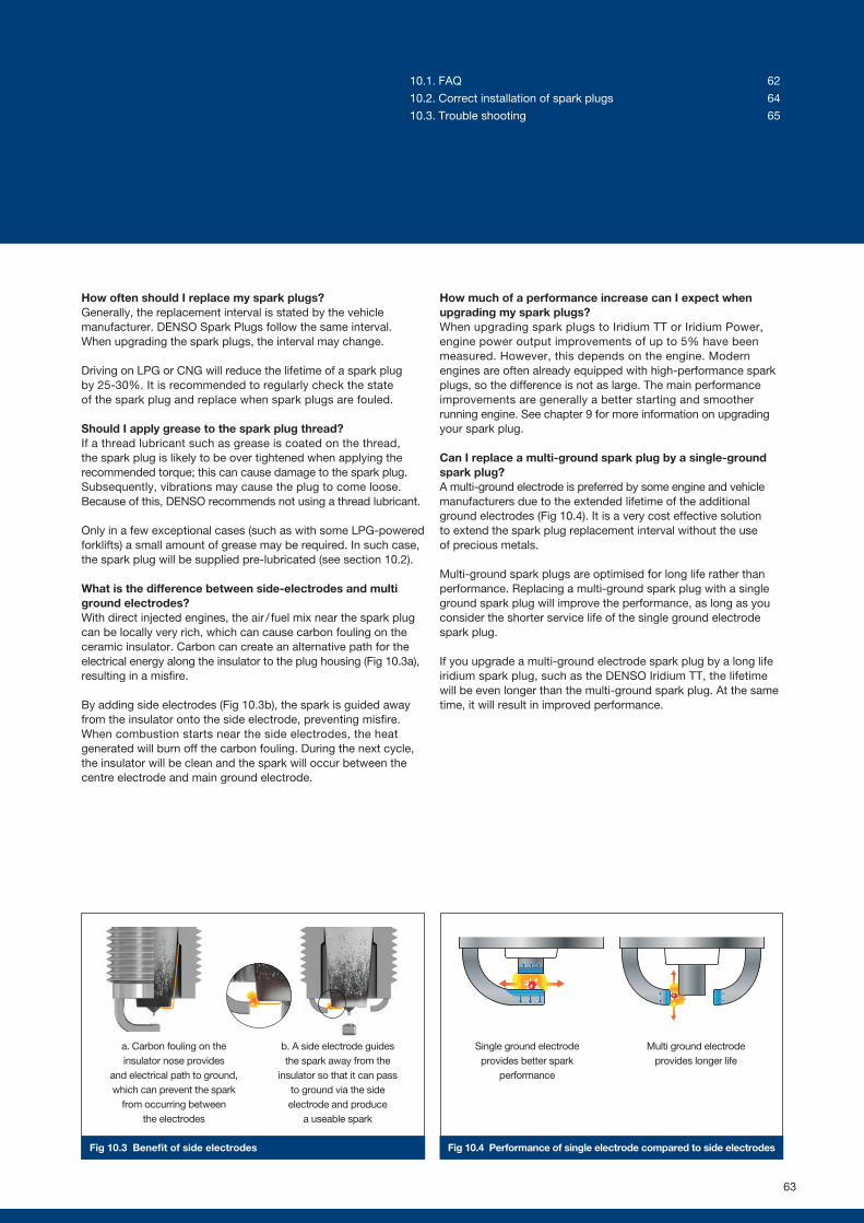
Fig 10.3 Benefit of side electrodes Fig 10.4 Performance of single electrode compared to side electrodes
How often should I replace my spark plugs?Generally, the replacement interval is stated by the vehicle manufacturer. DENSO Spark Plugs follow the same interval. When upgrading the spark plugs, the interval may change.
Driving on LPG or CNG will reduce the lifetime of a spark plug by 25-30%. It is recommended to regularly check the state of the spark plug and replace when spark plugs are fouled.
Should I apply grease to the spark plug thread?If a thread lubricant such as grease is coated on the thread, the spark plug is likely to be over tightened when applying the recommended torque; this can cause damage to the spark plug. Subsequently, vibrations may cause the plug to come loose. Because of this, DENSO recommends not using a thread lubricant.
Only in a few exceptional cases (such as with some LPG-powered forklifts) a small amount of grease may be required. In such case, the spark plug will be supplied pre-lubricated (see section 10.2).
What is the difference between side-electrodes and multi ground electrodes?With direct injected engines, the air / fuel mix near the spark plug can be locally very rich, which can cause carbon fouling on the ceramic insulator. Carbon can create an alternative path for the electrical energy along the insulator to the plug housing (Fig 10.3a), resulting in a misfire.
By adding side electrodes (Fig 10.3b), the spark is guided away from the insulator onto the side electrode, preventing misfire. When combustion starts near the side electrodes, the heat generated will burn off the carbon fouling. During the next cycle, the insulator will be clean and the spark will occur between the centre electrode and main ground electrode.
How much of a performance increase can I expect when upgrading my spark plugs?When upgrading spark plugs to Iridium TT or Iridium Power, engine power output improvements of up to 5% have been measured. However, this depends on the engine. Modern engines are often already equipped with high-performance spark plugs, so the difference is not as large. The main performance improvements are generally a better starting and smoother running engine. See chapter 9 for more information on upgrading your spark plug.
Can I replace a multi-ground spark plug by a single-ground spark plug?A multi-ground electrode is preferred by some engine and vehicle manufacturers due to the extended lifetime of the additional ground electrodes (Fig 10.4). It is a very cost effective solution to extend the spark plug replacement interval without the use of precious metals.
Multi-ground spark plugs are optimised for long life rather than performance. Replacing a multi-ground spark plug with a single ground spark plug will improve the performance, as long as you consider the shorter service life of the single ground electrode spark plug.
If you upgrade a multi-ground electrode spark plug by a long life iridium spark plug, such as the DENSO Iridium TT, the lifetime will be even longer than the multi-ground spark plug. At the same time, it will result in improved performance.
a. Carbon fouling on the insulator nose provides
and electrical path to ground, which can prevent the spark
from occurring between the electrodes
Multi ground electrode provides longer life
Single ground electrode provides better spark
performance
b. A side electrode guides the spark away from the
insulator so that it can pass to ground via the side electrode and produce
a useable spark
63
10.1. FAQ 62
10.2. Correct installation of spark plugs 64
10.3. Trouble shooting 65
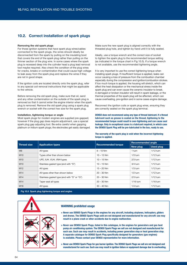
Fig 10.5 Spark plug tightening torque and angles
10.2. Correct installation of spark plugs
Removing the old spark plugsFor those ignition systems that have spark plug wires/cables connected to the spark plugs, the wires should ideally be disconnected from the spark by pulling on the insulating boot that covers the end of the spark plug rather than pulling on the thinner section of the plug wire. In some cases where the spark plug is recessed deep into the cylinder head a plug lead removal tool maybe required. Also check the condition of the plug wires for cracks, breaks or contamination that could cause high voltage to leak away from the spark plug and replace the wires if they are not in good shape.
If the ignition coils are located directly onto the spark plug, refer to any special coil removal instructions that might be applicable to the vehicle.
Before removing the old spark plug, make sure that oil, sand and any other contamination on the outside of the spark plug is removed so that it cannot enter the engine interior when the spark plug is removed. Remove the old spark plug using a spark plug wrench or socket with the correct hex size for the spark plug.
Installation, tightening torque or angleMost spark plugs for modern engines are supplied pre-gapped; however if the plug gap does require adjustment, use a special spark plug gap adjusting tool. Be extra careful when gapping platinum or iridium spark plugs; the electrodes get easily damaged.
Make sure the new spark plug is aligned correctly with the threaded plug hole, and tighten by hand until it is fully seated.
Ideally, use a torque wrench and the correct size of socket to tighten the spark plug to the recommended torque setting (as indicated in the torque chart in Fig 10.5). If a torque wrench is not available, use the recommended tightening angle.
It is very important to use the correct tightening torque when installing spark plugs. If insufficient torque is applied, leaks can occur causing a loss of pressure from the combustion chamber especially during the compression and ignition/combustion strokes. If too much torque is applied, the housing will stretch, which can affect the heat dissipation or the mechanical stress inside the spark plug and can even cause the ceramic insulator to break. A damaged or broken insulator will result in spark leakage, or the thermal properties of the spark plug will be affected, which can cause overheating, pre-ignition and in some cases engine damage.
Reconnect the ignition coils or spark plug wires, ensuring they are correctly seated on the spark plug terminal.
DENSO does not recommend using any type of thread lubricant. If a thread lubricant such as grease is coated on the thread, tightening to the recommended torque could result in over-tightening and can cause seal leakage. Only in exceptional cases is a lubricant required, in which case the DENSO Spark Plug will be pre-lubricated in the box, ready to use.
The warranty of the spark plug is void when the incorrect tightening torque is applied.
Thread size Application types Recommended torqueRecommended angle
New plug Used plug
M8 All types 8 – 10 Nm 1 turn 1/12 turn
M10 Types other than shown below 10 – 15 Nm 1/3 turn 1/12 turn
M10 UFE, IUH, VUH, VNH types 10 – 15 Nm 2/3 turn 1/12 turn
M10 Stainless gasket type (end with “S”) 10 – 15 Nm 3/4 turn 1/12 turn
M12 All types 15 – 20 Nm 1/3 turn 1/12 turn
M14 All types other than shown below 20 – 30 Nm 1/2 turn 1/12 turn
M14 Stainless gasket type (end with “S” or “G”) 20 – 30 Nm 2/3 turn 1/12 turn
M14 Taper seat all types 20 – 30 Nm 1/16 turn 1/16 turn
M18 All types 30 – 40 Nm 1/4 turn 1/12 turn
WARNING prohibited usage
> Never use DENSO Spark Plugs in the engines for any aircraft, including airplanes, helicopters, gliders and drones. The DENSO Spark Plugs sold are not designed and manufactured for any aircraft: use may result in a plane crash or other accidents due to engine malfunction.
> Never use DENSO Spark Plugs, listed in this catalogue, in the engines for generators and gas heat pump air conditioning system. The DENSO Spark Plugs we sell are not designed and manufactured for such use. Such use may result in accidents, including power generation stop or heat generation stop. A separate catalogue for DENSO Spark Plug specifically designed for generators (gas engines) is available. Please contact your DENSO representative for more information.
> Never use DENSO Spark Plugs for gas burner ignition. The DENSO Spark Plugs we sell are not designed and manufactured for such use. Such use may result in ignition failure or equipment damage due to overheating.
64
10. FAQ, INSTALLATION AND TROUBLE SHOOTING
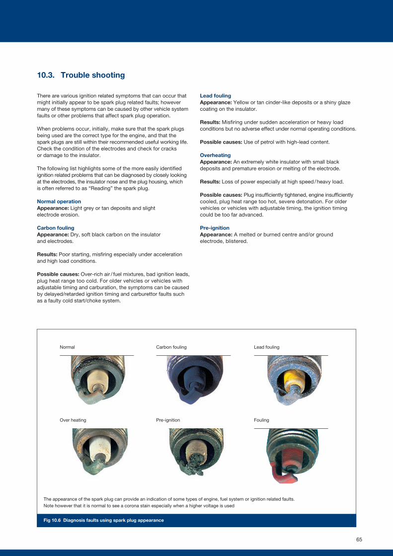
Normal
Over heating
Carbon fouling
Pre-ignition
Lead fouling
Fouling
10.3. Trouble shooting
There are various ignition related symptoms that can occur that might initially appear to be spark plug related faults; however many of these symptoms can be caused by other vehicle system faults or other problems that affect spark plug operation.
When problems occur, initially, make sure that the spark plugs being used are the correct type for the engine, and that the spark plugs are still within their recommended useful working life. Check the condition of the electrodes and check for cracks or damage to the insulator.
The following list highlights some of the more easily identified ignition related problems that can be diagnosed by closely looking at the electrodes, the insulator nose and the plug housing, which is often referred to as “Reading” the spark plug.
Normal operationAppearance: Light grey or tan deposits and slight electrode erosion.
Carbon foulingAppearance: Dry, soft black carbon on the insulator and electrodes.
Results: Poor starting, misfiring especially under acceleration and high load conditions.
Possible causes: Over-rich air / fuel mixtures, bad ignition leads, plug heat range too cold. For older vehicles or vehicles with adjustable timing and carburation, the symptoms can be caused by delayed/retarded ignition timing and carburettor faults such as a faulty cold start/choke system.
Lead foulingAppearance: Yellow or tan cinder-like deposits or a shiny glaze coating on the insulator.
Results: Misfiring under sudden acceleration or heavy load conditions but no adverse effect under normal operating conditions.
Possible causes: Use of petrol with high-lead content.
OverheatingAppearance: An extremely white insulator with small black deposits and premature erosion or melting of the electrode.
Results: Loss of power especially at high speed / heavy load.
Possible causes: Plug insufficiently tightened, engine insufficiently cooled, plug heat range too hot, severe detonation. For older vehicles or vehicles with adjustable timing, the ignition timing could be too far advanced.
Pre-ignitionAppearance: A melted or burned centre and/or ground electrode, blistered.
The appearance of the spark plug can provide an indication of some types of engine, fuel system or ignition related faults. Note however that it is normal to see a corona stain especially when a higher voltage is used
Fig 10.6 Diagnosis faults using spark plug appearance
65

DENSO Europe B.V. Hogeweyselaan 165, 1382 JL Weesp
The Netherlands
Tel: +31 294 493 493 I Fax: +31 294 417 122
www.denso-am.eu


