Page 1
HAL Id: hal-02324436https://hal-centralesupelec.archives-ouvertes.fr/hal-02324436
Submitted on 21 Oct 2019
HAL is a multi-disciplinary open accessarchive for the deposit and dissemination of sci-entific research documents, whether they are pub-lished or not. The documents may come fromteaching and research institutions in France orabroad, or from public or private research centers.
L’archive ouverte pluridisciplinaire HAL, estdestinée au dépôt et à la diffusion de documentsscientifiques de niveau recherche, publiés ou non,émanant des établissements d’enseignement et derecherche français ou étrangers, des laboratoirespublics ou privés.
Spatial Modulation for Multiple-AntennaCommunication
Marco Renzo, Harald Haas, Ali Ghrayeb, Lajos Hanzo, Shinya Sugiura
To cite this version:Marco Renzo, Harald Haas, Ali Ghrayeb, Lajos Hanzo, Shinya Sugiura. Spatial Modulation forMultiple-Antenna Communication. John G. Webster. Wiley Encyclopedia of Electrical and Electron-ics Engineering, 2016, �10.1002/047134608X.W8327�. �hal-02324436�
Page 2
See discussions, stats, and author profiles for this publication at: https://www.researchgate.net/publication/310599151
Spatial Modulation for Multiple‐Antenna Communication
Chapter · November 2016
DOI: 10.1002/047134608X.W8327
CITATIONS
6READS
1,118
5 authors, including:
Some of the authors of this publication are also working on these related projects:
spatial modulation View project
Ultra-reliable and low-latency communication (URLLC) systems View project
Marco Di Renzo
French National Centre for Scientific Research
278 PUBLICATIONS 6,456 CITATIONS
SEE PROFILE
Ali Ghrayeb
Texas A&M University at Qatar
239 PUBLICATIONS 4,973 CITATIONS
SEE PROFILE
L. Hanzo
University of Southampton
2,411 PUBLICATIONS 33,523 CITATIONS
SEE PROFILE
All content following this page was uploaded by L. Hanzo on 25 September 2017.
The user has requested enhancement of the downloaded file.
Page 3
Spatial Modulation for Multiple-Antenna
Communication
Marco Di Renzo, Senior Member, IEEE, Harald Haas, Member, IEEE,
Ali Ghrayeb, Senior Member, IEEE, Shinya Sugiura, Senior Member, IEEE, and
Lajos Hanzo, Fellow, IEEE
Abstract
The key challenge of future mobile communication networks is to strike an attractive compromise
between the wireless network’s area spectral efficiency and energy efficiency. This necessitates new
approaches to wireless system design, embracing a rich body of existing knowledge - especially in the
field of Multiple-Input-Multiple-Output (MIMO) techniques. Hence in this chapter, we describe Spatial
Modulation (SM), which constitutes a promising new concept of wireless system design conceived
for reducing the number of high-cost RF front-ends compared to other MIMO implementations. The
concept of SM has recently established itself as a beneficial transmission paradigm, subsuming numerous
members of the MIMO system-family. Research activities on SM have reached sufficient maturity to
motivate its comparison against state-of-the-art MIMO systems, as well as to inspire its application in
emerging wireless communication systems. Furthermore, it has received sufficient research attention to
motivate its implemention in testbeds and it holds the promise of stimulating further vigorous inter-
disciplinary research in the years to come, especially in the emerging market of the Internet of Things
(IoT).
Index Terms
Manuscript December 22, 2015.
M. Di Renzo is with the Laboratoire des Signaux et Systemes, CNRS, CentraleSupelec, Univ Paris Sud, Universite Paris-
Saclay, 3 rue Joliot Curie, Plateau du Moulon, 91192, Gif-sur-Yvette, France (e-mail: [email protected] ).
H. Haas is with The University of Edinburgh, Institute for Digital Communications (IDCOM), Mayfield Road, Edinburgh,
EH9 3JL, United Kingdom (e-mail: [email protected] ).
A. Ghrayeb is with the Department of Electrical and Computer Engineering, Texas A&M University at Qatar (e-mail:
[email protected] ).
S. Sugiura is with the Department of Computer and Information Sciences, Tokyo University of Agriculture and Technology,
Tokyo, 184-8588, Japan (e-mail: [email protected] ).
L. Hanzo is with The University of Southampton, Communications, Signal Processing and Control Group, Department of
Electronics and Computer Science, SO17 1BJ, United Kingdom (e-mail: [email protected] ).
Page 4
WILEY ENCYCLOPEDIA OF THE IEEE 1
Multiple-antenna systems, spatial modulation, few-RF multiple-antenna design, cellular networks,
connected objects.
I. INTRODUCTION
It is widely recognized that the Long Term Evolution (LTE) is the de facto physical-layer
standard of fourth generation (4G) cellular networks [1], [2]. The power consumption of the
Information and Communication Technology (ICT) sector in the next decade will highly depend
on the Energy Efficiency (EE) of this physical-layer standard [3], [4]. At the current stage,
however, the LTE standard may be deemed to be conceived, designed and optimized based on
the Spectral Efficiency (SE), with limited consideration of the associated EE issues [5]. Hence the
primary focus has been on achieving high data rates, without giving much cognizance to EE and
to the implementation complexity, especially at the physical-layer. This approach, unfortunately,
is no longer acceptable for future services relying on cellular networks. The recent research
efforts and the decision to standardize a new narrow-band radio technology for the Internet of
Things (IoT) confirm this paradigm change. The new radio access network standard is known as
the Narrow-Band IoT (NB-IoT) recommendation, which is expected to provide improved indoor
coverage, to support a massive number of low-throughput devices, to guarantee a limited delay,
to facilitate a low device cost as well as power consumption and so on [6]. This technology is
expected to operate “in-band”, relying on the resource blocks of a standard LTE carrier, or in
the unused resource blocks within a LTE carrier’s guard-band, or in a “stand-alone” mode for
emloyment in dedicated spectrum.
The operational LTE physical-layer standard relies on Multiple-Input-Multiple-Output (MIMO)
techniques for enhancing the SE and for reducing the transmit power [7], [8]. MIMO aided
techniques will undoubtedly find their way into the fifth generation (5G) of mobile services
and applications. In emerging IoT applications, on the other hand, the so-called connected
objects are expected to require modest data rates, a low power consumption, and a smaller
form factor compared to those of typical mobile multi-media services. By contrast, they are
expected to support higher data rates at a higher power consumption, and at a more bulky form
factor compared to typical wireless sensor networks. Hence, new air-interface techniques have
to be developed, which are capable of satisfying these new emerging requirements. Clearly,
MIMO transmission and reception schemes will continue to play a vital role in these emerging
Page 5
WILEY ENCYCLOPEDIA OF THE IEEE 2
application scenarios, in light of their inherent design flexibility. However, new MIMO paradigms
are necessary.
In simple terms, the capacity of MIMO systems is proportional to min{Nt, Nr}, where Nt and
Nr represent the number of transmit and receive antennas. This implies that the throughput may
be increased linearly with the number of antennas. As a consequence, MIMO techniques can
provide high data rates without any bandwidth-expansion and without increasing the transmit
power [7]. However, in practice, MIMO systems rely on a multiplicity of associated circuits,
such as power amplifiers, RF front-ends, mixers, synthesizers, filters, etc., which substantially
increase the circuit power dissipation of all network elements. More explicitly, recent studies have
clearly shown that the EE gain of MIMO transmission increases with the number of antennas,
provided that only the transmit power is taken into account and their circuit power dissipation
is neglected [9], [10], [11]. On the other hand, the EE gain of MIMO transmission remains
modest and decreases with the number of active transmit antennas, if realistic power consumption
models are considered [12]. These results highlight that the design of energy efficient and low-
complexity MIMO transmission is an open research problem at the time of writing, especially in
the context of IoT applications. In fact, many system parameters have to be considered, such as
the bandwidth, the transmit power, the number of active transmit/receive antennas, the number
of active devices, etc., which all contribute to the fundamental transmit power vs. circuit power
dissipation and multiplexing gain vs. inter-user interference trade-offs. As a result, while the SE
advantages of MIMO transmission are widely recognized, its EE potential is not well understood.
Conventional MIMO transmission takes advantage of all the antennas available at the trans-
mitter, by simultaneously transmitting multiple data streams from all of them. Thus, all transmit
antennas are activated at any time instance. By appropriately choosing the transmission/precoding
matrices, multiplexing (higher data rates) and/or transmit-diversity (better link reliability) gains
can be obtained using MIMO systems. The reason behind this choice is that simultaneously
activating all transmit antennas results in an improved SE [8]. However, unfortunately, this
choice does not lead to optimizing the total EE [12]. In fact, multiple RF chains are required
at both the transmitter and receiver for simultaneously transmitting many data streams, each
of which requires an independent power amplifier that is known to dissipate the majority of
the power consumed [3]. These considerations imply that a major challenge of next-generation
MIMO-aided cellular networks is the design of multi-antenna transmission schemes with a limited
Page 6
WILEY ENCYCLOPEDIA OF THE IEEE 3
number of RF front-ends, aiming for reducing the complexity, for relaxing both the inter-antenna
synchronization requirements, the inter-channel interference, as well as the signal processing
complexity and the form factor of the network elements, whilst aiming for improving the SE
compared to single-antenna transmission and for reducing the total power consumption compared
to conventional multiple-antenna aided transmission.
In this context, the design of MIMO transmission schemes that exploit fewer RF chains com-
pared to the number of available radiating elements is currently emerging as a promising research
field [13]. Usually, this family of MIMO designs is referred to as a single-RF MIMO. Suffice
to say, however that there are also various compromise-schemes, which rely on diverse antenna-
selection schemes, where a specific fraction of the antennas is activated, which determines the
number of RF-chains necessitated. Hence in parlance we can refer to these schemes as single-RF,
full-RF and fractional-RF arrangements.
To elaborate a little further, the fundamental idea behind the fractional-RF aided MIMO
schemes is to attain spatial multiplexing and/or transmit-diversity gains with the aid of many
antenna-elements, where only a fraction of the antenna-elements - or possibly just a single
antenna-element - is activated at the transmitter at any modulation instant. The rationale behind
the full-RF to fractional-RF paradigm shift in MIMO design originates from the consideration that
multiple transmit antennas (radiating elements) may be accommodated at both the transmitters
and receivers, bearing in mind that the complexity and power consumption/dissipation of MIMO
transmission is mainly determined by the number of simultaneously active transmit antennas,
i.e., by the number of RF chains [9], [10].
Fueled by these considerations, SM has recently established itself as a promising transmission
concept, which belongs to the fractional-RF MIMO wireless system family, whilst exploiting the
availability of multiple antennas in a novel fashion compared to state-of-the-art high-complexity
and power-hungry classic MIMO systems [14]. In simple terms, SM can be regarded as a MIMO
concept that possesses a larger set of radiating elements than the number of transmit-electronics
chains. SM-MIMO takes advantage of the entire antenna-array at the transmitter, whilst using
a limited number of RF chains. The main distinguishing feature of SM-MIMO is that it maps
additional information bits onto a “SM constellation diagram”, where each constellation element
is constituted by either a single one or a subset of antenna-elements. These unique characteristics
result in high-rate MIMO implementations relying on a reduced signal processing and circuit
Page 7
WILEY ENCYCLOPEDIA OF THE IEEE 4
complexity, as well as an improved EE. Recent analytical and simulation studies have shown that
SM-MIMOs have the inherent potential of outperforming many state-of-the-art MIMO schemes
under the fair assumption that the number of RF chains is the same.
In a nutshell, the rationale behind SM-MIMO communications designed for spectral- and
energy-efficient cellular networks is supported by a pair of main pillars: 1) Given the performance
constraints, they minimize the number of activated antenna-elements in order to increase the EE
by reducing the circuit power consumption and the form factor of the devices; 2) Given the
implementation and size constraints, they maximize the number of radiating antenna-elements
in order to increase both the SE and the EE by reducing the transmit power consumption. This
is realized by capitalizing on the multiplexing gain introduced by mapping additional bits onto
the so-called “SM constellation diagram” constituted by the antennas.
Against this back-drop, in this chapter the concept of SM-MIMO is introduced and its achiev-
able performance in terms of its error probability, signal processing complexity and energy
efficiency is discussed. Finally, experimental results relying on a testbed are illustrated in order
to substantiate the feasibility of this emerging concept.
II. A HISTORICAL PERSPECTIVE
Although SM-MIMO has received widespread attention from the research community only
in the last few years (about 11 papers were available in the open technical literature in 2008),
it is a 14-year old technology. In this section, we briefly describe the history of SM-MIMO
research with a focus on some pioneering papers, where the concept of SM is first proposed and
studied. From this short glimpse into the historical development of SM-MIMO, it is evident that
during the years 2001-2008 various researchers independently developed transmission concepts
closely-related to the SM-MIMO scheme, which were nicknamed with different acronyms.
The “space modulation” principle appeared for the first time in 2001 [15]. This scheme was
termed as Space Shift Keying (SSK) modulation and it exploits the differences in the signals
received from different Transmit Antennas (TAs) to discriminate the transmitted information
messages. In [15], a twin-antenna MIMO setup providing 1 bit-per-channel-use (bpcu) transmis-
sion was investigated. The information bits are encoded by keeping one TA active all the time,
while activating the second TA only for one of the two possible information bits. The authors
also proposed a twin-antenna MIMO setup that combines spatial and binary Phase Shift Keying
Page 8
WILEY ENCYCLOPEDIA OF THE IEEE 5
(PSK) modulation, thus providing 2 bpcu transmission. The scheme employs 2-PSK modulation,
when the TAs are active.
A year later in 2002, Haas et al. [16] the authors proposed a multi-antenna modulation scheme,
where a number of bits that is equal to that of the TA-elements is multiplexed in an orthogonal
fashion. A special property of the encoding scheme is that only one out of the available TAs is
active in every channel use. The scheme is developed for 2-PSK modulation and some bits are
used as parity checks. The authors show that it provides the same spectral efficiency as 8-PSK,
but with a better error probability.
Two years later in 2004, Song et al. [17] proposed a modulation scheme termed as the “channel
hopping technique,” which is exactly what is known today as SM-MIMO. The idea is portrayed
in [17, Fig. 1], and it foresees the transmission of two information streams: the first is explicitly
transmitted by using conventional PSK or Quadrature Amplitude Modulation (QAM) and the
second is implicitly transmitted by activating a single TA of the available antenna-array.
In 2005, Mesleh et al. [18] independently proposed the same modulation scheme as in [17].
The main motivation behind [18] is to develop a multi-antenna modulation scheme that avoids
Inter-Antenna Interference (IAI), which is realized by activating a single TA in every channel
use and by implicitly conveying additional information bits using the TA switching process. The
authors also show that the proposed scheme significantly relaxes the signal processing complexity
at the receiver. In 2006, the same authors further investigated the scheme proposed in [18] and
they used for the first time the terminology of “Spatial Modulation” to identify this transmission
mechanism [19], [20], [21], [22].
Two years later in 2008, various papers were published by improving and further investigating
the SM-MIMO concepts presented in the previous years. Yang and Jiao et al. [23] study the
channel capacity, where the parlance of Information Guided Channel Hopping (IGCH) is coined.
It is shown that IGCH provides a better spectral efficiencies than Orthogonal Space Time Block
Codes (OSTBCs). In [24], the SM-MIMO concept introduced in [18], [19], [20], [21], [22] is
comprehensively studied by using a low-complexity two-step demodulator. In [25], the authors
develop the Maximum Likelihood (ML) optimum demodulator for SM-MIMO and they show
that some performance improvements can be expected compared to the sub-optimal demodulator
introduced in [24]. In [26], the SM-MIMO scheme is simplified by generalizing the SSK
concept originally proposed in [15] to arbitrary numbers of TAs. In particular, only the spatial-
Page 9
WILEY ENCYCLOPEDIA OF THE IEEE 6
constellation diagram is used to transmit information bits. This encoding scheme is today known
as SSK-MIMO. In [27], a framework is introduced for the performance analysis of SM-MIMO
by using results from ordered statistics. In [28], the authors extend [26] by allowing more than
one TA to be active in every channel use and by encoding the information bits onto various
combinations of multiple active TAs. They show that for the same number of TA-elements the
rate can be improved at the cost of increasing the number of RF chains, whilst tolerating some
performance loss. This modulation scheme is referred to as Generalized SSK (GSSK).
More recently, in [29], [30], [31], [32], [33] the issue of fast RF switching has been addressed in
the context of SM/SSK, which is a major practical implementation challenge of these techniques.
Due to the specific encoding mechanism of SM/SSK, the active transmit antenna is switched at
each new channel use, which requires an RF switch operating at the symbol rate. While fast RF
switches with low insertion loss and with good isolation properties are available in the literature
for a wide range of frequency bands, high-speed RF switches still constitute a critical part of the
transmitter design [34]. To this end, single-RF MIMO systems have been implemented using the
concept of reconfigurable antennas (RAs). Indeed, the implementation of SM/SSK using a single
RA with multiple transmission states allows for replacing the switching amongst RF chains by
a switching operation amongst antenna states. The latter process is associated with modifying
the surface current distribution within the RA and thus it is associated with a lower complexity
and lower cost than switching amongst RF chains during each transmission period.
At the time of writing, research on SM-MIMO is well established and hundreds of research
contributions are available in the open technical literature. The interested readers are invited to
consult recent survey papers in this field of research [14], [34], [35], [36], [37].
III. OPERATING PRINCIPLE
A. How It Works
In this section, we introduce the SM-MIMO concept illustrating it with the aid of some
simple examples. We denote by Nt and Nr the number TAs and Receive Antennas (RAs),
respectively. The cardinality of the signal-constellation diagram is denoted by M . Either PSK or
QAM are considered. In general, Nt, Nr and M can be chosen independently of each other. At
the receiver, ML-optimum demodulation is considered. Thus, Nr can be chosen independently
of Nt [7]. For ease of presentation, we assume Nt = 2nt and M = 2m with nt and m being
Page 10
WILEY ENCYCLOPEDIA OF THE IEEE 7
Fig. 1. Illustration of three MIMO concepts: (a) spatial-multiplexing; (b) transmit-diversity; and (c) spatial modulation.
Reproduced with permission from [34].
two positive integers. For ease of illustration, a single RF front-end is supposed to be available
at the transmitter (single-RF MIMO).
In Fig. 1, the SM-MIMO concept is illustrated for Nt = M = 2 and it is compared to the
conventional Spatial Multiplexing (SMX) scheme [7, Sec. II] and to the OSTBC scheme designed
for transmit-diversity [7, Sec. III]. In the latter case, the Alamouti scheme is considered as an
example [38].
1) In SMX-MIMO, two PSK/QAM symbols (S1 and S2) are simultaneously transmitted from
a pair of TAs in a single channel use. For arbitrary Nt and M , the rate of SMX is
RSMX = Nt log2 (M) bpcu [7, Sec. II].
2) In OSTBC-MIMO, two PSK/QAM symbols (S1 and S2) are first encoded and then simul-
Page 11
WILEY ENCYCLOPEDIA OF THE IEEE 8
taneously transmitted from a pair of TAs in two channel uses. For arbitrary Nt and M ,
the rate of OSTBC is ROSTBC = Rc log2 (M) bpcu, where Rc = NM/Ncu ≤ 1 is the rate
of the space-time block code and NM is the number of information symbols transmitted in
Ncu channel uses [7, Sec. III], [39]. If, as shown in Fig. 1, the Alamouti code is chosen,
then we have Rc = 1 [38].
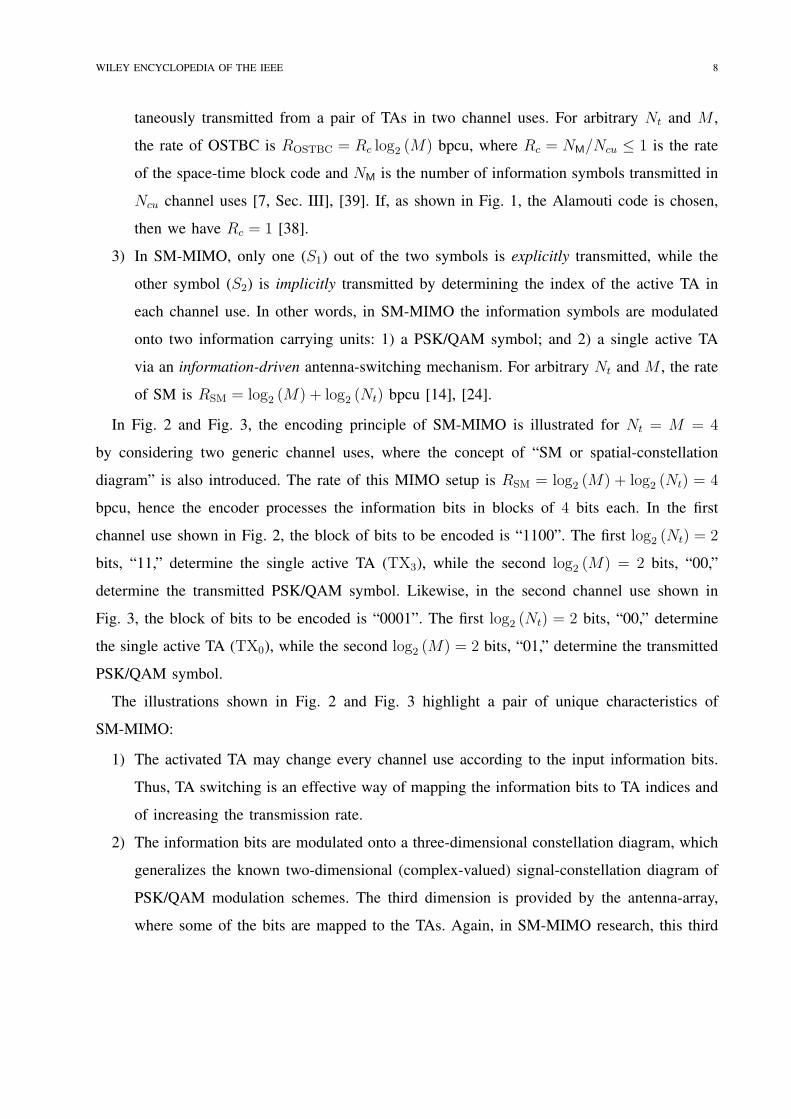
3) In SM-MIMO, only one (S1) out of the two symbols is explicitly transmitted, while the
other symbol (S2) is implicitly transmitted by determining the index of the active TA in
each channel use. In other words, in SM-MIMO the information symbols are modulated
onto two information carrying units: 1) a PSK/QAM symbol; and 2) a single active TA
via an information-driven antenna-switching mechanism. For arbitrary Nt and M , the rate
of SM is RSM = log2 (M) + log2 (Nt) bpcu [14], [24].
In Fig. 2 and Fig. 3, the encoding principle of SM-MIMO is illustrated for Nt = M = 4
by considering two generic channel uses, where the concept of “SM or spatial-constellation
diagram” is also introduced. The rate of this MIMO setup is RSM = log2 (M) + log2 (Nt) = 4
bpcu, hence the encoder processes the information bits in blocks of 4 bits each. In the first
channel use shown in Fig. 2, the block of bits to be encoded is “1100”. The first log2 (Nt) = 2
bits, “11,” determine the single active TA (TX3), while the second log2 (M) = 2 bits, “00,”
determine the transmitted PSK/QAM symbol. Likewise, in the second channel use shown in
Fig. 3, the block of bits to be encoded is “0001”. The first log2 (Nt) = 2 bits, “00,” determine
the single active TA (TX0), while the second log2 (M) = 2 bits, “01,” determine the transmitted
PSK/QAM symbol.
The illustrations shown in Fig. 2 and Fig. 3 highlight a pair of unique characteristics of
SM-MIMO:
1) The activated TA may change every channel use according to the input information bits.
Thus, TA switching is an effective way of mapping the information bits to TA indices and
of increasing the transmission rate.
2) The information bits are modulated onto a three-dimensional constellation diagram, which
generalizes the known two-dimensional (complex-valued) signal-constellation diagram of
PSK/QAM modulation schemes. The third dimension is provided by the antenna-array,
where some of the bits are mapped to the TAs. Again, in SM-MIMO research, this third
Page 12
WILEY ENCYCLOPEDIA OF THE IEEE 9
Fig. 2. Illustration of the three-dimensional encoding of spatial modulation (first channel use) Reproduced from [34] with
permission.
dimension is often termed as the “spatial-constellation diagram” [14].
In simple mathematical terms, the signal model of SM-MIMO, assuming a frequency-flat
channel model, is as follows:
y = Hx+ n (1)
where: i) y ∈ CNr×1 is the complex received vector; ii) H ∈ C
Nr×Nt is the complex channel
matrix; iii) n ∈ CNr×1 is the complex Additive White Gaussian Noise (AWGN) at the receiver;
and iv) x = es ∈ CNt×1 is the complex modulated vector with s ∈ M ⊆ C
1×1 being the
complex (scalar) PSK/QAM modulated symbol belonging to the signal-constellation diagram
and e ∈ A being the Nt× 1 vector belonging to the spatial-constellation diagram A as follows:
et =
1 if the t− th TA is activated
0 if the t− th TA is not activated(2)
Page 13
WILEY ENCYCLOPEDIA OF THE IEEE 10
Fig. 3. Illustration of the three-dimensional encoding of spatial modulation (second channel use) Reproduced from [34] with
permission.
where et is the tth entry of e for t = 1, 2, . . . , Nt. In other words, the points (Nt-dimensional
vectors) of the spatial-constellation diagram are the Nt unit vectors of the natural basis of the
Nt-dimensional Euclidean space.
If Nt = 1, SM-MIMO reduces to conventional single-antenna communications, where the
information bits are encoded only onto the signal-constellation diagram. In this case, the rate
is R0 = log2 (M). On the other hand, if M = 1 the information is encoded only onto the
spatial-constellation diagram by providing a rate equal to RSSK = log2 (Nt). In the literature,
this transmission scheme is known as SSK modulation [26]. In particular, SSK modulation
is a MIMO scheme, where data transmission takes place only through the information-driven
TA switching mechanism. It is apparent that SM-MIMO can be viewed as the combination of
single-antenna PSK/QAM and SSK-MIMO modulations.
Page 14
WILEY ENCYCLOPEDIA OF THE IEEE 11
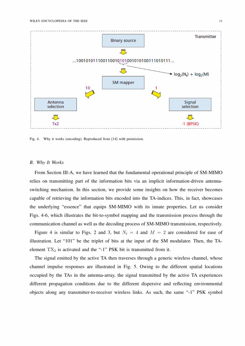
Fig. 4. Why it works (encoding). Reproduced from [14] with permission.
B. Why It Works
From Section III-A, we have learned that the fundamental operational principle of SM-MIMO
relies on transmitting part of the information bits via an implicit information-driven antenna-
switching mechanism. In this section, we provide some insights on how the receiver becomes
capable of retrieving the information bits encoded into the TA-indices. This, in fact, showcases
the underlying “essence” that equips SM-MIMO with its innate properties. Let us consider
Figs. 4-6, which illustrates the bit-to-symbol mapping and the transmission process through the
communication channel as well as the decoding process of SM-MIMO transmission, respectively.
Figure 4 is similar to Figs. 2 and 3, but Nt = 4 and M = 2 are considered for ease of
illustration. Let “101” be the triplet of bits at the input of the SM modulator. Then, the TA-
element TX2 is activated and the “-1” PSK bit is transmitted from it.
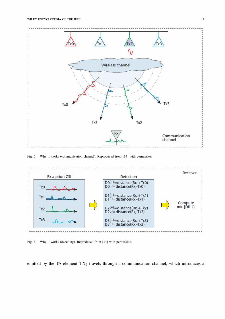
The signal emitted by the active TA then traverses through a generic wireless channel, whose
channel impulse responses are illustrated in Fig. 5. Owing to the different spatial locations
occupied by the TAs in the antenna-array, the signal transmitted by the active TA experiences
different propagation conditions due to the different dispersive and reflecting environmental
objects along any transmitter-to-receiver wireless links. As such, the same “-1” PSK symbol
Page 15
WILEY ENCYCLOPEDIA OF THE IEEE 12
Fig. 5. Why it works (communication channel). Reproduced from [14] with permission.
Fig. 6. Why it works (decoding). Reproduced from [14] with permission.
emitted by the TA-element TX2 travels through a communication channel, which introduces a
Page 16
WILEY ENCYCLOPEDIA OF THE IEEE 13
specific “channel signature or fingerprint,” i.e., the channel impulse response, that makes it unique
compared to the same symbol emitted by any other TAs. This constitutes the fundamental essence
of SM-MIMO: the more different the channel signatures/fingerprints are from each other, the
simpler it becomes to distinguish the signals at the receiver. In simple terms, the communication
channel may be deemed to play, especially for SSK-MIMO, the role of a “modulation unit,”
where the channel impulse responses are the actual messages being transmitted.
At the receiver, the demodulation unit exploits the unique fingerprint introduced by the
wireless channel for retrieving the information bits. This is illustrated in Fig. 6, where a coherent
demodulation scheme based on the minimum Euclidean distance is considered [25]. The receiver
is assumed to be aware of the Nt channel impulse responses, however the actual channel impulse
response that is received in each channel use depends on the index of the active TA. The
demodulator performs an exhaustive search among all the possible combinations of channel
impulse responses and modulation symbols, and makes a decision in favor of the hypothesis
associated with the lowest Euclidean distance. In a nutshell, due to the information-driven
antenna-switching mechanism of SM-MIMO transmission, the Nt channel impulse responses
become part of the search space of the hypothesis-testing problem solved by the receiver.
Based on the estimated channel impulse response, the demodulator is capable of retrieving
the information bits associated with it. In summary, the essence of SM-MIMO transmission is
all about exploiting the TA-specific property of the wireless channel, i.e., the uniqueness of each
transmit-to-receive wireless link, for data communication.
IV. ACHIEVABLE PERFORMANCE
In this section, we illustrate some numerical examples showing the achievable performance
of SM-MIMO in terms of its bit error probability, signal processing complexity and energy
efficiency.
In Fig. 7, the bit error probability of SM-MIMO is illustrated. The setup encompasses a
MIMO transmission channel with independent and identically distributed Rayleigh fading. The
receiver is equipped with Nr receive antennas and the transmitter is configured with a single RF
front-end. The target data rate is 8 bpcu. The modulation scheme and the number of transmit
antennas Nt are chosen accordingly. In addition, SM-MIMO is compared against SMX-MIMO
that is configured for achieving the same data rate. The figure shows that SM-MIMO is capable
Page 17
WILEY ENCYCLOPEDIA OF THE IEEE 14
Fig. 7. Bit Error Probability. Reproduced from [40] with permission.
of providing better error performance than SMX-MIMO, under the assumption that a sufficient
number of antenna-elements is available at the transmitter. Furthermore, this is achieved by using
fewer RF front-ends than SMX-MIMO.
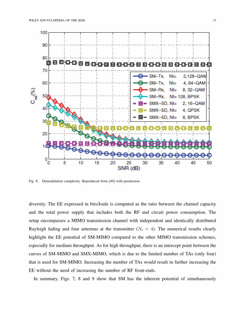
In Fig. 8, the signal processing complexity of SM-MIMO demodulation is illustrated. The same
setup as in Fig. 7 is used. In particular, the demodulator is based on the Sphere Decoding (SD)
principle [40] and it is shown in terms of the number of complex-valued operations with respect
to the baseline ML-optimum demodulator. The figure points out that SM-MIMO is capable of
offering a significant reduction of the signal processing complexity with respect to SMX-MIMO.
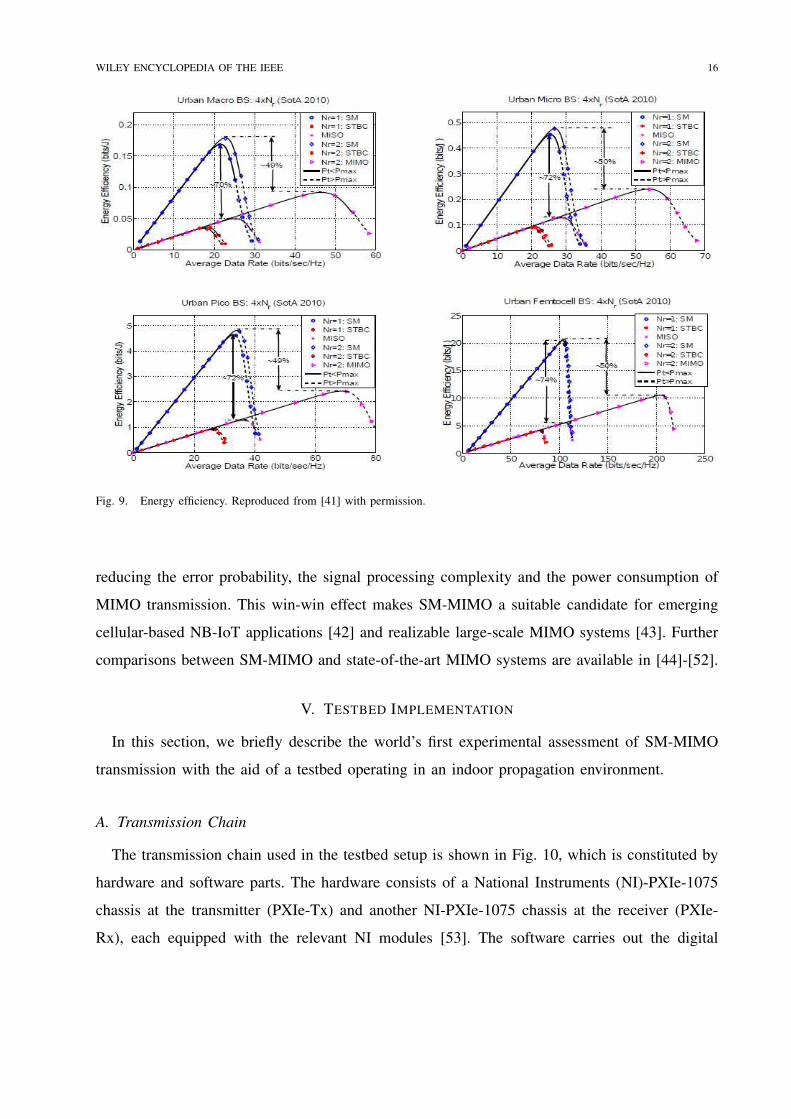
In Fig. 9, the EE potential of SM-MIMO is illustrated and compared against SMX-MIMO,
OSTBCs (3/4 code rate) and Multiple-Input-Single-Output (SIMO) transmission for transmit-
Page 18
WILEY ENCYCLOPEDIA OF THE IEEE 15
Fig. 8. Demodulation complexity. Reproduced from [40] with permission.
diversity. The EE expressed in bits/Joule is computed as the ratio between the channel capacity
and the total power supply that includes both the RF and circuit power consumption. The
setup encompasses a MIMO transmission channel with independent and identically distributed
Rayleigh fading and four antennas at the transmitter (Nt = 4). The numerical results clearly
highlight the EE potential of SM-MIMO compared to the other MIMO transmission schemes,
especially for medium throughput. As for high throughput, there is an intercept point between the
curves of SM-MIMO and SMX-MIMO, which is due to the limited number of TAs (only four)
that is used for SM-MIMO. Increasing the number of TAs would result in further increasing the
EE without the need of increasing the number of RF front-ends.
In summary, Figs. 7, 8 and 9 show that SM has the inherent potential of simultaneously
Page 19
WILEY ENCYCLOPEDIA OF THE IEEE 16
Fig. 9. Energy efficiency. Reproduced from [41] with permission.
reducing the error probability, the signal processing complexity and the power consumption of
MIMO transmission. This win-win effect makes SM-MIMO a suitable candidate for emerging
cellular-based NB-IoT applications [42] and realizable large-scale MIMO systems [43]. Further
comparisons between SM-MIMO and state-of-the-art MIMO systems are available in [44]-[52].
V. TESTBED IMPLEMENTATION
In this section, we briefly describe the world’s first experimental assessment of SM-MIMO
transmission with the aid of a testbed operating in an indoor propagation environment.
A. Transmission Chain
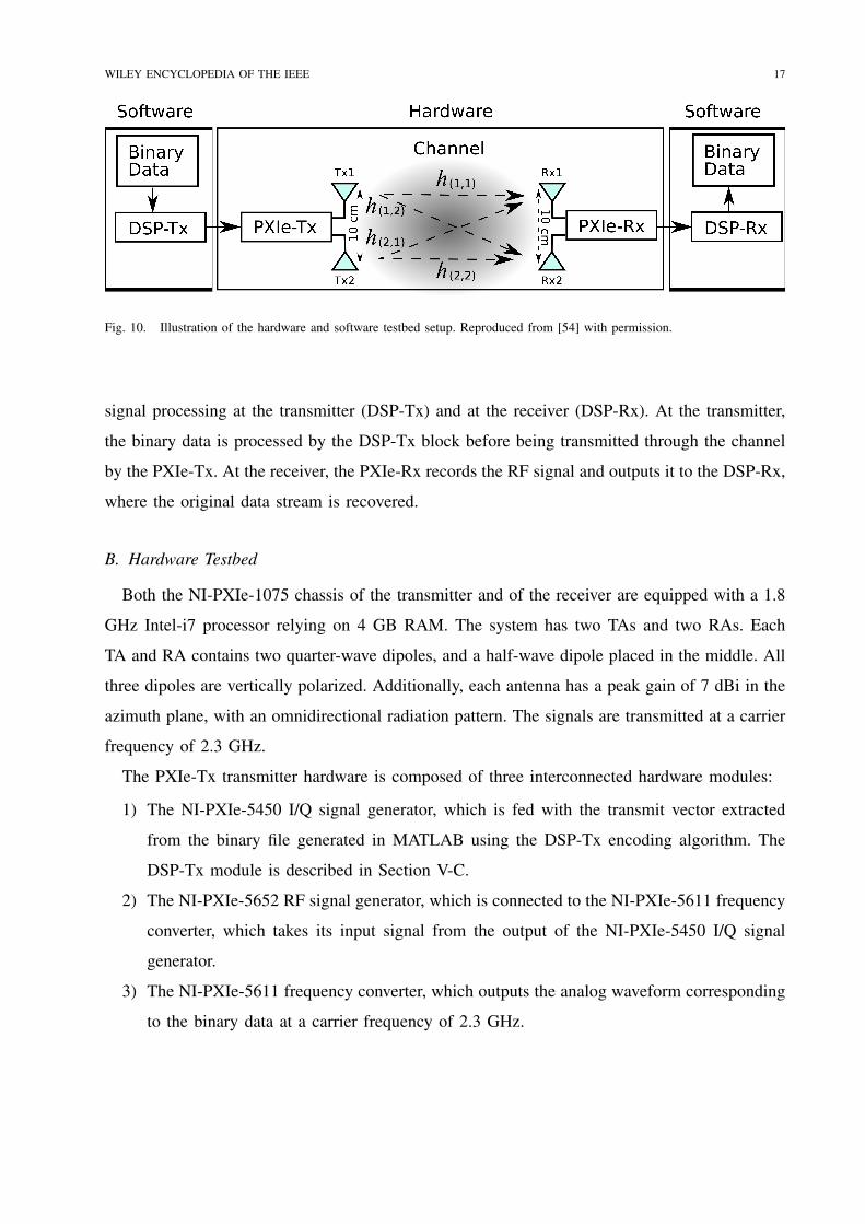
The transmission chain used in the testbed setup is shown in Fig. 10, which is constituted by
hardware and software parts. The hardware consists of a National Instruments (NI)-PXIe-1075
chassis at the transmitter (PXIe-Tx) and another NI-PXIe-1075 chassis at the receiver (PXIe-
Rx), each equipped with the relevant NI modules [53]. The software carries out the digital
Page 20
WILEY ENCYCLOPEDIA OF THE IEEE 17
Hardware
Fig. 10. Illustration of the hardware and software testbed setup. Reproduced from [54] with permission.
signal processing at the transmitter (DSP-Tx) and at the receiver (DSP-Rx). At the transmitter,
the binary data is processed by the DSP-Tx block before being transmitted through the channel
by the PXIe-Tx. At the receiver, the PXIe-Rx records the RF signal and outputs it to the DSP-Rx,
where the original data stream is recovered.
B. Hardware Testbed
Both the NI-PXIe-1075 chassis of the transmitter and of the receiver are equipped with a 1.8
GHz Intel-i7 processor relying on 4 GB RAM. The system has two TAs and two RAs. Each
TA and RA contains two quarter-wave dipoles, and a half-wave dipole placed in the middle. All
three dipoles are vertically polarized. Additionally, each antenna has a peak gain of 7 dBi in the
azimuth plane, with an omnidirectional radiation pattern. The signals are transmitted at a carrier
frequency of 2.3 GHz.
The PXIe-Tx transmitter hardware is composed of three interconnected hardware modules:
1) The NI-PXIe-5450 I/Q signal generator, which is fed with the transmit vector extracted
from the binary file generated in MATLAB using the DSP-Tx encoding algorithm. The
DSP-Tx module is described in Section V-C.
2) The NI-PXIe-5652 RF signal generator, which is connected to the NI-PXIe-5611 frequency
converter, which takes its input signal from the output of the NI-PXIe-5450 I/Q signal
generator.
3) The NI-PXIe-5611 frequency converter, which outputs the analog waveform corresponding
to the binary data at a carrier frequency of 2.3 GHz.
Page 21
WILEY ENCYCLOPEDIA OF THE IEEE 18
Framing
SM Modulation
Pilot and Zero Padding
Up Sampling and
Filtering
Sync and SNR
Binary Data
Tuning
Signal
Power
Binary file for Tx1
Binary file for Tx2
DSP-Tx
Frequency Offset
Correction
Down Sampling and
Filtering
Extract Frames
SNR Calculation
Synchronisation
Channel
Estimation
SM De-Modulation
Binary Data
Binary file from Rx1
Binary file from Rx2
DSP-Rx
Fig. 11. Block-diagram of signal processing modules implemented at the transmitter and receiver. Reproduced from [54] with
permission.
Likewise, the PXIe-Rx receiver hardware is composed of three interconnected hardware mod-
ules:
1) The NIPXIe-5601 RF down-converter, which is used for detecting the analog RF signal
from the RAs.
2) The NI-PXIe-5652 on-board reference clock, which is used for synchronization.
3) The NI-PXIe-5622 IF digitizer, which applies its own bandpass filter and produces the
received binary files that are processed in MATLAB by the DSP-Rx decoding algorithm.
The DSP-Rx module is described in Section V-C.
C. Software Testbed
MATLAB is used for the digital signal processing required both at the transmitter and receiver,
DSP-Tx and DSP-Rx, respectively. DSP-Tx processes the incoming information and generates
a file that can be transmitted by PXIe-Tx. DSP-Rx processes the data received by PXIe-Rx and
Page 22
WILEY ENCYCLOPEDIA OF THE IEEE 19
recovers the original binary data stream. The processing algorithms at DSP-Tx and DSP-Rx are
shown in Fig. 11.
The following operations are implemented at the DSP-Tx:
1) The binary data is first split into information segments of appropriate size.
2) The information in each segment is then modulated using SM-MIMO.
3) A pilot signal is incorporated for the sake of channel estimation along with a frequency
offset estimation section.
4) Then, zero-padding is performed, which permits up-sampling of the data, while maintaining
the same signal power. The up-sampling ratio is set to four and the up-sampled data is
passed through a root raised cosine finite impulse response filter with 40 taps and a roll-off
factor of 0.75. A large roll-off factor and a long tap-delay are necessary for ensuring that
the power is focused to a short time window, i.e., for ensuring that only a single antenna
is activated in every channel use.
5) The resultant vector is multiplied by a factor termed as the “Tuning Signal Power” for the
sake of adjusting the desired transmit power required for the information sequence.
6) The frames are created by ensuring that the frame length multiplied by the sampling rate is
less than the coherence time of the channel, which is typically about 7 ms for a stationary
indoor environment. This ensures that all channel estimates generated at the receiver are
valid for the frame duration.
The following operations are implemented at DSP-Rx:
1) The raw data vectors received from the NI-PXIe-5622 digitizer are combined, in order to
form the received matrix for data demodulation.
2) The detector first finds the beginning of the transmitted sequence by using the synchro-
nization sequence (based on an autocorrelation algorithm).
3) The Signal-to-Noise-Ratio (SNR) for each vector is calculated using the “SNR section”.
4) Each raw vector is decomposed into its underlying frames.
5) Each frame is down-sampled and passed through a root raised cosine filter which completes
the matched-filtering.
6) Frequency offset estimation, timing recovery and correction of each frame follow, which
rely on using state-of-the-art algorithms.
Page 23
WILEY ENCYCLOPEDIA OF THE IEEE 20
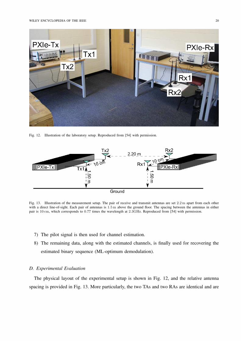
Fig. 12. Illustration of the laboratory setup. Reproduced from [54] with permission.
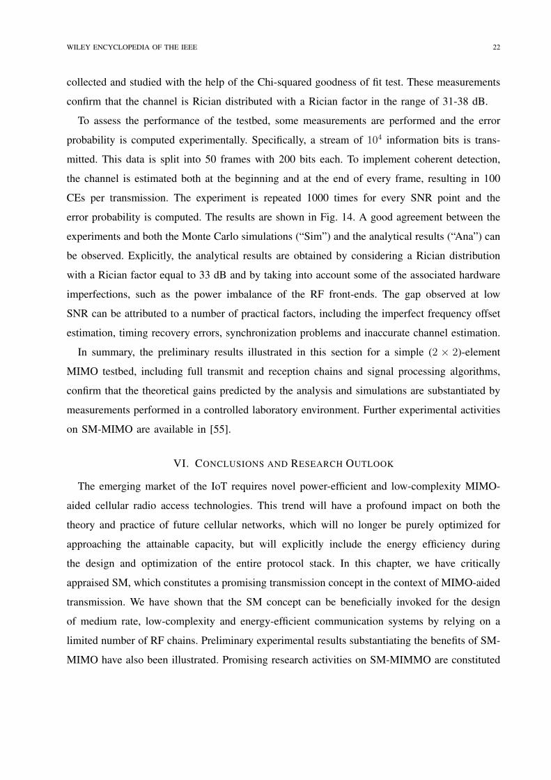
Fig. 13. Illustration of the measurement setup. The pair of receive and transmit antennas are set 2.2m apart from each other
with a direct line-of-sight. Each pair of antennas is 1.5m above the ground floor. The spacing between the antennas in either
pair is 10 cm, which corresponds to 0.77 times the wavelength at 2.3GHz. Reproduced from [54] with permission.
7) The pilot signal is then used for channel estimation.
8) The remaining data, along with the estimated channels, is finally used for recovering the
estimated binary sequence (ML-optimum demodulation).
D. Experimental Evaluation
The physical layout of the experimental setup is shown in Fig. 12, and the relative antenna
spacing is provided in Fig. 13. More particularly, the two TAs and two RAs are identical and are
Page 24
WILEY ENCYCLOPEDIA OF THE IEEE 21
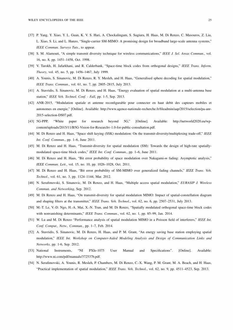
Fig. 14. Illustration of the experimental results and comparison with analysis and simulations. Reproduced from [54] with
permission.
placed directly across each other. As such, the channel between the transmitter and receiver has a
strong LoS component. Therefore, the transmit-to-receive channel exhibits a Rician distribution
with a high Rician factor due to the short distance between transmitter and receiver. In order to
confirm the Rician distribution and to estimate the Rician factor, some channel measurements are
Page 25
WILEY ENCYCLOPEDIA OF THE IEEE 22
collected and studied with the help of the Chi-squared goodness of fit test. These measurements
confirm that the channel is Rician distributed with a Rician factor in the range of 31-38 dB.
To assess the performance of the testbed, some measurements are performed and the error
probability is computed experimentally. Specifically, a stream of 104 information bits is trans-
mitted. This data is split into 50 frames with 200 bits each. To implement coherent detection,
the channel is estimated both at the beginning and at the end of every frame, resulting in 100
CEs per transmission. The experiment is repeated 1000 times for every SNR point and the
error probability is computed. The results are shown in Fig. 14. A good agreement between the
experiments and both the Monte Carlo simulations (“Sim”) and the analytical results (“Ana”) can
be observed. Explicitly, the analytical results are obtained by considering a Rician distribution
with a Rician factor equal to 33 dB and by taking into account some of the associated hardware
imperfections, such as the power imbalance of the RF front-ends. The gap observed at low
SNR can be attributed to a number of practical factors, including the imperfect frequency offset
estimation, timing recovery errors, synchronization problems and inaccurate channel estimation.
In summary, the preliminary results illustrated in this section for a simple (2 × 2)-element
MIMO testbed, including full transmit and reception chains and signal processing algorithms,
confirm that the theoretical gains predicted by the analysis and simulations are substantiated by
measurements performed in a controlled laboratory environment. Further experimental activities
on SM-MIMO are available in [55].
VI. CONCLUSIONS AND RESEARCH OUTLOOK
The emerging market of the IoT requires novel power-efficient and low-complexity MIMO-
aided cellular radio access technologies. This trend will have a profound impact on both the
theory and practice of future cellular networks, which will no longer be purely optimized for
approaching the attainable capacity, but will explicitly include the energy efficiency during
the design and optimization of the entire protocol stack. In this chapter, we have critically
appraised SM, which constitutes a promising transmission concept in the context of MIMO-aided
transmission. We have shown that the SM concept can be beneficially invoked for the design
of medium rate, low-complexity and energy-efficient communication systems by relying on a
limited number of RF chains. Preliminary experimental results substantiating the benefits of SM-
MIMO have also been illustrated. Promising research activities on SM-MIMMO are constituted
Page 26
WILEY ENCYCLOPEDIA OF THE IEEE 23
by amalgamating the SM concept with reconfigurable antennas, aiming for the design of cellular
systems supporting low-cost, low-complexity, low-power consumption and medium-throughput
IoT applications [42].
We close this chapter by directing interested readers to a collection of companion tutorial
slides [56] and a tutorial YouTube video [57] on SM-MIMO research.
REFERENCES
[1] http://www.3gpp.org/lte-advanced.
[2] A. Ghosh, J. Zhang, J. G. Andrews, and R. Muhamed, Fundamentals of LTE, Prentice-Hall, June 2010.
[3] Z. Hasan, H. Boostanimehr, and V. K. Bhargava, “Green cellular networks: A survey, some research issues and challenges,”
IEEE Commun. Surveys Tuts., vol. 13, no. 4, pp. 524–540, Nov. 2011.
[4] M. Di Renzo, L. Alonso, F. H. P. Fitzek, A. Foglar, F. Granelli, F. Graziolsky, C. Gruet, H. Haas, G. Kormentzas, A. I. Perez,
J. Rodriguez, J. Thompson, and C. Verikoukis, “GREENET - An early stage training network in enabling technologies for
green radio,” IEEE Veh. Technol. Conf. - Workshops, pp. 1–5, May 2011.
[5] 3GPP TSG-SA#50 SP-1008883GPP, 3GPP Work Item Description, Study on system enhancements for energy efficiency,
3GPP TSGSA, Istanbul, Turkey, Tech. Rep., Dec. 2010, agreed Work Item 500037 (Release 11).
[6] 3GPP Narrow-Band Internet of Things. [Online]. Available: http://www.3gpp.org/news-events/3gpp-news/1733-niot.
[7] J. Mietzner, R. Schober, L. Lampe, W. H. Gerstacker, and P. A. Hoeher, “Multiple-antenna techniques for wireless
communications - A comprehensive literature survey,” IEEE Commun. Surveys Tuts., vol. 11, no. 2, pp. 87–105, 2nd
quarter 2009.
[8] H. Huang, C. B. Papadias, and S. Venkatesan, MIMO Communication for Cellular Networks, Springer, Nov. 2011.
[9] S. D. Gray, “Theoretical and practical considerations for the design of green radio networks,” IEEE Veh. Technol. Conf. -
Spring, Keynote speech, May 2011. [Online]. Available: http://www.ieeevtc.org/conf-admin/vtc2011spring/5.pdf.
[10] G. Auer, V. Giannini, I. Godor, P. Skillermark, M. Olsson, M. Imran, D. Sabella, M. Gonzalez, C. Desset, and O. Blume,
“Cellular energy efficiency evaluation framework,” IEEE Veh. Technol. Conf. - Spring, pp. 1–6, May 2011.
[11] G. Auer, O. Blume, V. Giannini, I. Godor, M. Imran, Y. Jading, E. Katranaras, M. Olsson, D. Sabella, P. Skiller-
mark, and W. Wajda, “D2.3: Energy efficiency analysis of the reference systems, areas of improvements and target
breakdown,” EARTH: Energy Aware Radio and neTwork tecHnologies, Jan. 2012. [Online]. Available: https://bscw.ict-
earth.eu/pub/bscw.cgi/d71252/EARTH WP2 D2.3 v2.pdf.
[12] F. Heliot, M. A. Imran, and R. Tafazolli, “On the energy efficiency-spectral efficiency trade-off over the MIMO Rayleigh
fading channel,” IEEE Trans. Commun., vol. 60, no. 5, pp. 1345–1356, May 2012.
[13] A. Mohammadi and F. M. Ghannouchi, “Single RF front-end MIMO transceivers,” IEEE Commun. Mag., vol. 49, no. 12,
pp. 104–109, Dec. 2011.
[14] M. Di Renzo, H. Haas, and P. M. Grant, “Spatial modulation for multiple-antenna wireless systems: A survey,” IEEE
Commun. Mag., vol. 49, no. 12, pp. 182–191, Dec. 2011.
[15] Y. Chau and S.-H. Yu, “Space modulation on wireless fading channels,” IEEE Veh. Technol. Conf. - Fall, pp. 1668–1671,
Oct. 2001.
[16] H. Haas, E. Costa, and E. Schultz, “Increasing spectral efficiency by data multiplexing using antennas arrays,” IEEE Int.
Symp. Personal, Indoor, Mobile Radio Commun., pp. 610–613, Sep. 2002.
Page 27
WILEY ENCYCLOPEDIA OF THE IEEE 24
[17] S. Song, Y. L. Yang, Q. Xiong, K. Xie, B.-J. Jeong, and B. L. Jiao, “A channel hopping technique I: Theoretical studies
on band efficiency and capacity,” IEEE Int. Conf. Commun., Circuits and Systems, pp. 229–233, June 2004.
[18] R. Y. Mesleh, H. Haas, C. W. Ahn, and S. Yun “Interchannel interference avoidance in MIMO transmission by exploiting
spatial information,” IEEE Int. Symp. Personal, Indoor, Mobile Radio Commun., pp. 141–145, Sep. 2005.
[19] R. Y. Mesleh, H. Haas, C. W. Ahn, and S. Yun, “Spatial modulation - OFDM,” Int. OFDM Workshop, pp. 288–292, Aug.
2006.
[20] S. Ganesan, R. Y. Mesleh, H. Haas, C. W. Ahn, and S. Yun, “On the performance of spatial modulation OFDM,” Asilomar
Conf. Signals, Systems Computers, pp. 1825–1829, Oct. 2006.
[21] R. Y. Mesleh, H. Haas, C. W. Ahn, and S. Yun, “Spatial modulation - A new low complexity spectral efficiency enhancing
technique,” IEEE Int. Conf. Commun. Netw. in China, pp. 1–5, Oct. 2006.
[22] R. Y. Mesleh, S. Ganesan, and H. Haas, “Impact of channel imperfections on spatial modulation OFDM,” IEEE Int. Conf.
Commun. Netw. in China, pp. 1–5, Sep. 2007.
[23] Y. Yang and B. Jiao, “Information-guided channel-hopping for high data rate wireless communication,” IEEE Commun.
Lett., vol. 12, no. 4, pp. 225–227, Apr. 2008.
[24] R. Y. Mesleh, H. Haas, S. Sinanovic, C. W. Ahn, and S. Yun, “Spatial modulation,” IEEE Trans. Veh. Technol., vol. 57,
no. 4, pp. 2228–2241, July 2008.
[25] J. Jeganathan, A. Ghrayeb, and L. Szczecinski, “Spatial modulation: Optimal detection and performance analysis,” IEEE
Commun. Lett., vol. 12, no. 8, pp. 545–547, Aug. 2008.
[26] J. Jeganathan, A. Ghrayeb, L. Szczecinski, and A. Ceron, “Space shift keying modulation for MIMO channels,” IEEE
Trans. Wireless Commun., vol. 8, no. 7, pp. 3692–3703, July 2009.
[27] R. Y. Mesleh, S. Engelken, S. Sinanovic, and H. Haas, “Analytical SER calculation of spatial modulation,” IEEE Int. Symp.
Spread Spectrum Tech. Applic., pp. 272–276, Aug. 2008.
[28] J. Jeganathan, A. Ghrayeb, and L. Szczecinski, “Generalized space shift keying modulation for MIMO channels,” IEEE
Int. Symp. Personal, Indoor, Mobile Radio Commun., pp. 1–5, Sep. 2008.
[29] S. Sugiura, “Coherent versus non-coherent reconfigurable antenna aided virtual MIMO systems,” IEEE Signal Processing
Letters, vol. 21, no. 4, pp. 390–394, April 2014.
[30] Z. Bouida, H. El-Sallabi, A. Ghrayeb, and K. A. Qaraqe, “Enhanced Space-Shift Keying (SSK) with Reconfigurable
Antennas,” IEEE Int. Conf. on Commun. (ICC’15), London, U.K, June 2015.
[31] Z. Bouida, H. El-Sallabi, A. Ghrayeb, and K. A. Qaraqe, “Reconfigurable Antenna-based Space-Shift Keying (SSK) for
MIMO Channels,” IEEE Trans. Commun., vol. 15, no. 1, pp. 446-457, January 2016.
[32] Z. Bouida, H. El-Sallabi, M. Abdallah, A. Ghrayeb, and K. A. Qaraqe, “Reconfigurable Antenna-Based Space-Shift Keying
for Spectrum Sharing Systems,” IEEE Int. Conf. on Commun. (ICC’16), Kuala Lumpur, Malaysia, May 2016.
[33] Z. Bouida, H. El-Sallabi, M. Abdallah, A. Ghrayeb, and K. A. Qaraqe, “Reconfigurable Antenna-Based Space-Shift Keying
for Spectrum Sharing Systems under Rician Fading,” IEEE Trans. Wireless Commun., 2nd round of reviews, February 2016.
[34] M. Di Renzo, H. Haas, A. Ghrayeb, S. Sugiura, and L. Hanzo, “Spatial modulation for generalized MIMO: Challenges,
opportunities and implementation,” Proc. of the IEEE, vol. 102, no. 1, pp. 56–103, Jan. 2014.
[35] S. Sugiura, S. Chen, and L. Hanzo, “A universal space-time architecture for multiple-antenna aided systems,” IEEE
Commun. Surveys Tuts., vol. 14, no. 2, pp. 401–420, 2nd quarter 2012.
[36] P. Yang, M. Di Renzo, Y. Xiao, S. Li, and L. Hanzo, “Design guidelines for spatial modulation,” IEEE Commun. Surveys
Tuts., vol. 16, no. 1, pp. 6–26, 1st quarter 2015.
Page 28
WILEY ENCYCLOPEDIA OF THE IEEE 25
[37] P. Yang, Y. Xiao, Y. L. Guan, K. V. S. Hari, A. Chockalingam, S. Sugiura, H. Haas, M. Di Renzo, C. Masouros, Z. Liu,
L. Xiao, S. Li, and L. Hanzo, “Single-carrier SM-MIMO: A promising design for broadband large-scale antenna systems,”
IEEE Commun. Surveys Tuts., to appear.
[38] S. M. Alamouti, “A simple transmit diversity technique for wireless communications,” IEEE J. Sel. Areas Commun., vol.
16, no. 8, pp. 1451–1458, Oct. 1998.
[39] V. Tarokh, H. Jafarkhani, and R. Calderbank, “Space-time block codes from orthogonal designs,” IEEE Trans. Inform.
Theory, vol. 45, no. 5, pp. 1456–1467, July 1999.
[40] A. Younis, S. Sinanovic, M. Di Renzo, R. Y. Mesleh, and H. Haas, “Generalised sphere decoding for spatial modulation,”
IEEE Trans. Commun., vol. 61, no. 7, pp. 2805–2815, July 2013.
[41] A. Stavridis, S. Sinanovic, M. Di Renzo, and H. Haas, “Energy evaluation of spatial modulation at a multi-antenna base
station,” IEEE Veh. Technol. Conf. - Fall, pp. 1-5, Sep. 2013.
[42] ANR-2015, “Modulation spatiale et antenne reconfigurable pour connecter en haut debit des capteurs mobiles et
autonomes en energie,” [Online]. Available: http://www.agence-nationale-recherche.fr/fileadmin/aap/2015/selection/pa-anr-
2015-selection-DS07.pdf.
[43] 5G-PPP, “White paper for research beyond 5G,” [Online]. Available: http://networld2020.eu/wp-
content/uploads/2015/11/B5G-Vision-for-Researchv-1.0-for-public-consultation.pdf.
[44] M. Di Renzo and H. Haas, “Space shift keying (SSK) modulation: On the transmit-diversity/multiplexing trade-off,” IEEE
Int. Conf. Commun., pp. 1–6, June 2011.
[45] M. Di Renzo and H. Haas, “Transmit-diversity for spatial modulation (SM): Towards the design of high-rate spatially-
modulated space-time block codes,” IEEE Int. Conf. Commun., pp. 1–6, June 2011.
[46] M. Di Renzo and H. Haas, “Bit error probability of space modulation over Nakagami-m fading: Asymptotic analysis,”
IEEE Commun. Lett., vol. 15, no. 10, pp. 1026–1028, Oct. 2011.
[47] M. Di Renzo and H. Haas, “Bit error probability of SM-MIMO over generalized fading channels,” IEEE Trans. Veh.
Technol., vol. 61, no. 3, pp. 1124–1144, Mar. 2012.
[48] N. Serafimovski, S. Sinanovic, M. Di Renzo, and H. Haas, “Multiple access spatial modulation,” EURASIP J. Wireless
Commun. and Networking, Sep. 2012.
[49] M. Di Renzo and H. Haas, “On transmit-diversity for spatial modulation MIMO: Impact of spatial-constellation diagram
and shaping filters at the transmitter,” IEEE Trans. Veh. Technol., vol. 62, no. 6, pp. 2507–2531, July 2013.
[50] M.-T. Le, V.-D. Ngo, H.-A. Mai, X.-N. Tran, and M. Di Renzo, “Spatially modulated orthogonal space-time block codes
with nonvanishing determinants,” IEEE Trans. Commun., vol. 62, no. 1, pp. 85–99, Jan. 2014.
[51] W. Lu and M. Di Renzo “Performance analysis of spatial modulation MIMO in a Poisson field of interferers,” IEEE Int.
Conf. Comput., Netw., Commun., pp. 1–7, Feb. 2014.
[52] A. Stavridis, S. Sinanovic, M. Di Renzo, H. Haas, and P. M. Grant, “An energy saving base station employing spatial
modulation,” IEEE Int. Workshop on Computer-Aided Modeling Analysis and Design of Communication Links and
Networks, pp. 1-6, Sep. 2012.
[53] National Instruments, “NI PXIe-1075 User Manual and Specifications”. [Online]. Available:
http://www.ni.com/pdf/manuals/372537b.pdf.
[54] N. Serafimovski, A. Younis, R. Mesleh, P. Chambers, M. Di Renzo, C.-X. Wang, P. M. Grant, M. A. Beach, and H. Haas,
“Practical implementation of spatial modulation,” IEEE Trans. Veh. Technol., vol. 62, no. 9, pp. 4511–4523, Sep. 2013.
Page 29
WILEY ENCYCLOPEDIA OF THE IEEE 26
[55] A. Younis, W. Thompson, M. Di Renzo, C.-X. Wang, M. A. Beach, H. Haas, and P. M. Grant, “Performance of spatial
modulation using measured real-world channels,” IEEE Veh. Technol. Conf. - Fall, pp. 1–5, Sep. 2013.
[56] Spatial modulation for generalized MIMO: Challenges, opportunities and implementation. [Online]. Available: http://hal-
supelec.archives-ouvertes.fr/docs/00/87/50/26/ANNEX/ProcIEEE SMPaper Slides.pdf.
[57] Spatial modulation for generalized MIMO: Challenges, opportunities and implementation. [Online]. Available:
http://www.youtube.com/watch?v=cNgCJK4oimM&feature=youtu.be.
View publication statsView publication stats